EP3623295A1 - Flatterauskleidung für den einlass eines tiefen hohlraums - Google Patents
Flatterauskleidung für den einlass eines tiefen hohlraums Download PDFInfo
- Publication number
- EP3623295A1 EP3623295A1 EP19197406.2A EP19197406A EP3623295A1 EP 3623295 A1 EP3623295 A1 EP 3623295A1 EP 19197406 A EP19197406 A EP 19197406A EP 3623295 A1 EP3623295 A1 EP 3623295A1
- Authority
- EP
- European Patent Office
- Prior art keywords
- shroud
- attachment ring
- acoustic liner
- nacelle
- plenum
- Prior art date
- Legal status (The legal status is an assumption and is not a legal conclusion. Google has not performed a legal analysis and makes no representation as to the accuracy of the status listed.)
- Granted
Links
Images




Classifications
-
- F—MECHANICAL ENGINEERING; LIGHTING; HEATING; WEAPONS; BLASTING
- F02—COMBUSTION ENGINES; HOT-GAS OR COMBUSTION-PRODUCT ENGINE PLANTS
- F02K—JET-PROPULSION PLANTS
- F02K1/00—Plants characterised by the form or arrangement of the jet pipe or nozzle; Jet pipes or nozzles peculiar thereto
- F02K1/78—Other construction of jet pipes
- F02K1/82—Jet pipe walls, e.g. liners
- F02K1/827—Sound absorbing structures or liners
-
- B—PERFORMING OPERATIONS; TRANSPORTING
- B64—AIRCRAFT; AVIATION; COSMONAUTICS
- B64D—EQUIPMENT FOR FITTING IN OR TO AIRCRAFT; FLIGHT SUITS; PARACHUTES; ARRANGEMENT OR MOUNTING OF POWER PLANTS OR PROPULSION TRANSMISSIONS IN AIRCRAFT
- B64D29/00—Power-plant nacelles, fairings or cowlings
-
- B—PERFORMING OPERATIONS; TRANSPORTING
- B64—AIRCRAFT; AVIATION; COSMONAUTICS
- B64D—EQUIPMENT FOR FITTING IN OR TO AIRCRAFT; FLIGHT SUITS; PARACHUTES; ARRANGEMENT OR MOUNTING OF POWER PLANTS OR PROPULSION TRANSMISSIONS IN AIRCRAFT
- B64D33/00—Arrangement in aircraft of power plant parts or auxiliaries not otherwise provided for
- B64D33/02—Arrangement in aircraft of power plant parts or auxiliaries not otherwise provided for of combustion air intakes
-
- F—MECHANICAL ENGINEERING; LIGHTING; HEATING; WEAPONS; BLASTING
- F02—COMBUSTION ENGINES; HOT-GAS OR COMBUSTION-PRODUCT ENGINE PLANTS
- F02C—GAS-TURBINE PLANTS; AIR INTAKES FOR JET-PROPULSION PLANTS; CONTROLLING FUEL SUPPLY IN AIR-BREATHING JET-PROPULSION PLANTS
- F02C7/00—Features, components parts, details or accessories, not provided for in, or of interest apart form groups F02C1/00 - F02C6/00; Air intakes for jet-propulsion plants
- F02C7/04—Air intakes for gas-turbine plants or jet-propulsion plants
- F02C7/045—Air intakes for gas-turbine plants or jet-propulsion plants having provisions for noise suppression
-
- B—PERFORMING OPERATIONS; TRANSPORTING
- B64—AIRCRAFT; AVIATION; COSMONAUTICS
- B64D—EQUIPMENT FOR FITTING IN OR TO AIRCRAFT; FLIGHT SUITS; PARACHUTES; ARRANGEMENT OR MOUNTING OF POWER PLANTS OR PROPULSION TRANSMISSIONS IN AIRCRAFT
- B64D33/00—Arrangement in aircraft of power plant parts or auxiliaries not otherwise provided for
- B64D33/02—Arrangement in aircraft of power plant parts or auxiliaries not otherwise provided for of combustion air intakes
- B64D2033/0206—Arrangement in aircraft of power plant parts or auxiliaries not otherwise provided for of combustion air intakes comprising noise reduction means, e.g. acoustic liners
-
- F—MECHANICAL ENGINEERING; LIGHTING; HEATING; WEAPONS; BLASTING
- F05—INDEXING SCHEMES RELATING TO ENGINES OR PUMPS IN VARIOUS SUBCLASSES OF CLASSES F01-F04
- F05D—INDEXING SCHEME FOR ASPECTS RELATING TO NON-POSITIVE-DISPLACEMENT MACHINES OR ENGINES, GAS-TURBINES OR JET-PROPULSION PLANTS
- F05D2260/00—Function
- F05D2260/96—Preventing, counteracting or reducing vibration or noise
-
- Y—GENERAL TAGGING OF NEW TECHNOLOGICAL DEVELOPMENTS; GENERAL TAGGING OF CROSS-SECTIONAL TECHNOLOGIES SPANNING OVER SEVERAL SECTIONS OF THE IPC; TECHNICAL SUBJECTS COVERED BY FORMER USPC CROSS-REFERENCE ART COLLECTIONS [XRACs] AND DIGESTS
- Y02—TECHNOLOGIES OR APPLICATIONS FOR MITIGATION OR ADAPTATION AGAINST CLIMATE CHANGE
- Y02T—CLIMATE CHANGE MITIGATION TECHNOLOGIES RELATED TO TRANSPORTATION
- Y02T50/00—Aeronautics or air transport
- Y02T50/60—Efficient propulsion technologies, e.g. for aircraft
Definitions
- the present disclosure relates to a sound-absorbing arrangement for an engine nacelle and an engine nacelle comprising such an arrangement.
- a fan In modern aircraft engines a fan is used to create a thrust, with the fan being driven by a core engine.
- the fan is a major source of low-frequency engine noise, sometimes referred to as a "buzz saw" tone during aircraft takeoff and climb conditions, in the area in front of the engine, which may impact the comfort in the cabin in a negative way.
- coupled aeroelastic vibrations may occur as the mechanical vibrations of the fan blades and the flow surrounding them goes into resonance with the acoustic field that is formed around the fan.
- a nacelle inlet comprising an aft bulkhead, an attachment ring extending in an aft direction from the aft bulkhead, an acoustic liner disposed radially inward from the attachment ring, the acoustic liner comprising a proximal skin, a distal skin, and a core disposed between the proximal skin and the distal skin, and a shroud extending longitudinally between a forward side of the shroud and an aft side of the shroud and extending circumferentially between a first end of the shroud and a second end of the shroud, wherein the shroud defines a plenum disposed between the acoustic liner and the shroud, the plenum in fluid communication with the core via perforations in the distal skin.
- the plenum is at least partially defined by the attachment ring.
- the shroud comprises a longitudinal wall and a vertical wall.
- the shroud is bonded to at least one of the acoustic liner and the attachment ring.
- the shroud is coupled to at least one of the acoustic liner and the attachment ring via a plurality of fasteners.
- the attachment ring is configured to attach the nacelle inlet to a fan case.
- the first end of the shroud is coupled to an adjacent shroud.
- the shroud is coupled to the acoustic liner at the forward side of the shroud and the shroud is coupled to the attachment ring at the aft side of the shroud.
- a nacelle for a gas turbine engine comprising an inlet comprising an attachment ring, an acoustic liner, and a shroud extending longitudinally between a forward side of the shroud and an aft side of the shroud and extending circumferentially between a first end of the shroud and a second end of the shroud, and a fan case disposed aft of the inlet, wherein the acoustic liner is disposed radially inward from the attachment ring, the acoustic liner comprising a proximal skin, a distal skin, and a core disposed between the proximal skin and the distal skin, the shroud defines a plenum disposed between the acoustic liner and the shroud, the plenum in fluid communication with the core via perforations in the distal skin, and the inlet is coupled to the fan case via the attachment ring.
- the inlet further comprises an aft bulkhead, wherein the attachment ring extends in an aft direction from the aft bulkhead.
- the plenum is at least partially defined by the attachment ring.
- the shroud comprises a longitudinal wall and a vertical wall.
- the shroud is bonded to at least one of the acoustic liner and the attachment ring.
- the shroud is coupled to at least one of the acoustic liner and the attachment ring via a plurality of fasteners.
- the first end of the shroud is coupled to an adjacent shroud.
- the shroud is coupled to the acoustic liner at the forward side of the shroud and the shroud is coupled to the attachment ring at the aft side of the shroud.
- a method for manufacturing a nacelle inlet comprising coupling a shroud to an acoustic liner, and coupling the shroud to an attachment ring, wherein a plenum is formed between at least the shroud and the acoustic liner in response to coupling the shroud to the acoustic liner and the attachment ring, the plenum is fluid communication with a core of the acoustic liner.
- the shroud is coupled to the acoustic liner along a forward side of the shroud and the shroud is coupled to the attachment ring along an aft side of the shroud.
- coupling the shroud to the attachment ring includes coupling the shroud to a flange of the attachment ring.
- the method further comprises coupling the acoustic liner to the attachment ring, and coupling an aft bulkhead to the attachment ring.
- tail refers to the direction associated with the tail (e.g., the back end) of an aircraft, or generally, to the direction of exhaust of the gas turbine.
- forward refers to the direction associated with the nose (e.g., the front end) of an aircraft, or generally, to the direction of flight or motion.
- distal refers to the direction radially outward, or generally, away from the axis of rotation of a turbine engine.
- proximal refers to a direction radially inward, or generally, towards the axis of rotation of a turbine engine.
- outboard may define an element or portion of an element that is situated radially outer to or away from another, radially inward, element or portion of an element.
- an engine core may be situated radially inboard of an inner fixed structure ("IFS") and/or a fan casing, as described herein.
- inboard may define the element or portion of the element that is situated radially inward in relation to an outboard element.
- a shroud may partially define a backside plenum for an acoustic liner.
- a shroud, as disclosed herein, may provide a low weight and low cost solution for engine noise attenuation.
- a shroud, as disclosed herein, may be easily configurable for various inlet designs.
- a shroud, as disclosed herein, may provide ease of installation.
- FIG. 1 illustrates a schematic sectional view of a gas turbine engine.
- Gas turbine engine 110 may include core engine 120. Core air flow C flows through core engine 120 and is expelled through exhaust outlet 118 surrounding exhaust centerbody 122.
- Core engine 120 drives a fan 114 arranged in a bypass flow path 124.
- Bypass air flow B driven by the fan 114, flows in the aft direction through bypass flow path 124.
- At least a portion of bypass flow path 124 may be defined by nacelle structure 112 and inner fixed structure (IFS) 126.
- IFS inner fixed structure
- the general shape of IFS 126 is a surface of revolution around the engine axis, often with two bifurcation panels at the six o'clock and the twelve o'clock position which extend radially outward, and the IFS is often made from two generally mirror image halves that hinge together as part of the thrust reverser structure.
- the radially-outboard surface of IFS 126 may be referred to as an inner flow surface 136 of the bypass flow path 124, and the radially-inboard surface of nacelle structure 112 may be referred to as an outer flow surface 138 of the bypass flow path 124.
- Fan case 132 may surround fan 114. Fan case 132 may be housed within nacelle structure 112.
- an intermediate case (IMC) 134 of the gas turbine engine 110 may be provided radially inward of fan case 132.
- Fan case 132 may provide mounting structure for securing gas turbine engine 110 to a pylon.
- IMC 134 may be surrounded by nacelle structure 112.
- multiple guide vanes 116 may extend radially between fan case 132 and IMC 134.
- Core engine 120 may be secured to fan case 132 at IMC 134.
- a nacelle inlet 130 of the nacelle structure 112 may be provided axially forward of the fan case 132.
- Nacelle inlet 130 may comprise an aft bulkhead 102 and an attachment ring 104 coupled to the aft bulkhead 102 whereby nacelle inlet 130 is coupled to fan case 132.
- An acoustic liner 106 may be coupled to attachment ring 104. Acoustic liner 106 may at least partially define bypass flow path B.
- FIG. 2 illustrates a sectional view of a nacelle inlet 200, in accordance with various embodiments.
- nacelle inlet 200 is similar to nacelle inlet 130 of FIG. 1 .
- Nacelle inlet 200 may comprise an aft bulkhead 210 and an attachment ring 220 coupled to the aft bulkhead 210.
- attachment ring 220 may be attached to aft bulkhead 210 via a plurality of attachment features, such as bolts, rivets, or the like. Attachment ring 220 may be configured for coupling nacelle inlet 200 to an adjacent fan case.
- attachment ring 220 may comprise a first plurality of apertures 282 disposed therein whereby a plurality of fasteners - e.g., bolts - may secure attachment ring 220 to a fan case.
- attachment ring 220 may be configured to attach nacelle inlet 200 to a fan case.
- Attachment ring 220 may be made from a metal or metal alloy material.
- nacelle inlet 200 comprises an acoustic liner 230.
- Acoustic liner 230 may be coupled to attachment ring 220.
- Attachment ring 220 may comprise a second plurality of apertures 284 disposed therein whereby a plurality of fasteners - e.g., bolts, rivets, or the like - may secure acoustic liner 230 to attachment ring 220.
- Mechanical loads may be transferred between acoustic liner 230 and attachment ring 220, via the plurality of fasteners at second plurality of apertures 284.
- Acoustic liner 230 may comprise a permeable proximal skin 232, a mostly non-permeable distal skin 234 (except for perforations 235), and a core 236 disposed there between. Acoustic liner 230 may be a single degree of freedom (SDOF) acoustic liner.
- SDOF single degree of freedom
- nacelle inlet 200 comprises a shroud 250 defining a plenum 240 disposed between the shroud 250 and the acoustic liner 230.
- Plenum 240 may be partially defined by attachment ring 220, in accordance with various embodiments.
- Plenum 240 may be partially defined by aft bulkhead 210, in accordance with various embodiments.
- Plenum 240 is in fluid communication with core 236 and bypass flow path B via perforations 235 disposed in the distal skin 234.
- Shroud 250 may extend longitudinally (i.e., in the Z-direction) between a forward side 252 of the shroud 250 and an aft side 254 of the shroud 250.
- Plenum 240 may be formed between shroud 250, acoustic liner 230, and/or attachment ring 220 in response the shroud 250 being coupled to acoustic liner 230 and attachment ring 220.
- Forward side 252 may be coupled to distal skin 234.
- Aft side 254 may be coupled to attachment ring 220.
- forward side 252 is bonded to distal skin 234 via an adhesive 260, such as a glue or resin.
- aft side 254 is bonded to attachment ring 220 via an adhesive 260.
- shroud 250 may be configured as a non-structural component.
- shroud 250 is configured such that minimal to no mechanical loads are transferred between acoustic liner 230 and attachment ring 220 via shroud 250.
- shroud 250 may be configured as a thin, lightweight shroud, reducing overall nacelle weight and increasing design flexibility of the shroud 250.
- shroud 250 may be made from a composite material, such as a carbon fiber reinforced polymer, among others. Shroud 250 may be cured using a resin in a carbon fiber layup process, among others. In various embodiments, shroud 250 may be made from a metal, such as aluminum, among others. Shroud 250 may be formed using hydroforming, casting, additive manufacturing, negative manufacturing, and/or pressing processes, among others. Shroud 250 may comprise a thermoplastic material, such as an acrylic or a polycarbonate, among others. Shroud 250 may be formed using injection molding, compression molding, or extrusion, among others.
- shroud 250 may comprise a longitudinal wall 256 and a vertical wall 258.
- longitudinal wall 256 may be substantially parallel with respect to distal skin 234.
- vertical wall 258 may extend between longitudinal wall 256 and distal skin 234.
- Vertical wall 258 may be oriented at an angle 292 of between thirty degrees and one hundred and twenty degrees (30°-120°), and in various embodiments, at an angle 292 of between forty-five degrees and one hundred degrees (45°-100°), and in various embodiments, at an angle 292 of between sixty degrees and ninety degrees (60°-90°).
- shroud 250 is a non-load bearing shroud
- the orientation of vertical wall 258 is not particularly limited and may be designed according to the design of the nacelle inlet 200 and depending on the location of adjacent components.
- the angle 292 may vary around the circumference of the shroud 250 to accommodate for components located within the nacelle inlet.
- the height 290 of shroud 250 (i.e., the distance between longitudinal wall 256 of shroud 250 and distal skin 234 measured in the Y-direction (also referred to herein as a radial direction)) may be varied according to the desired acoustic properties of plenum 240, as well as in order to route shroud 250 around adjacent components within nacelle inlet 200.
- the cross sectional area of plenum 240 be maintained constant at every circumferential slice of plenum 240 and being able to adjust the height 290 of plenum 240 in combination with the longitudinal placement (i.e., in the Z-direction) and angle 292 of vertical wall 258 may be advantageous.
- the longitudinal placement of vertical wall 258 may be moved forward (i.e., negative Z-direction) to maintain a constant cross-sectional area of plenum 240 at every circumferential location.
- shroud 250 may comprise a first tab 257 at aft side 254 whereby shroud 250 is coupled to attachment ring 220. In various embodiments, shroud 250 may comprise a second tab 259 at forward side 252 whereby shroud 250 is coupled to distal skin 234.
- a nacelle inlet 300 is illustrated, in accordance with various embodiments.
- Nacelle inlet 300 may be similar to nacelle inlet 200 of FIG. 2 , except that nacelle inlet 300 comprises a double degree of freedom (DDOF) acoustic liner 330, as opposed to the SDOF acoustic liner 230 of FIG. 2 .
- Acoustic liner 330 may have a permeable septum 338 dividing a core 336 into two chambers. Acoustic liner 330 may comprise a permeable proximal skin 332, a mostly non-permeable distal skin 334 (except for perforations 335), and core 336 disposed there between.
- Nacelle inlet 300 may comprise a shroud 350.
- Shroud 350 may be similar to shroud 250 of FIG. 2 .
- Nacelle inlet 300 may comprise an aft bulkhead 310.
- Aft bulkhead 310 may be similar to aft bulkhead 210 of FIG. 2 .
- Nacelle inlet 300 may comprise an attachment ring 320.
- Attachment ring 320 may be similar to attachment ring 220 of FIG. 2 .
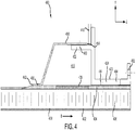
- FIG. 4 illustrates a sectional view of a nacelle inlet 400, in accordance with various embodiments.
- Nacelle inlet 400 may be similar to nacelle inlet 200 except that an attachment ring 420 of nacelle inlet 400 includes a forward extending flange 422 for attaching the shroud 450 to the attachment ring 420.
- Flange 422 may extend in the forward direction (i.e., the negative Z-direction) from attachment ring 420.
- flange 422 may be formed monolithically with attachment ring 420.
- aft side 454 of shroud 450 may be attached to attachment ring 420 without interfering with aft bulkhead 410 or other related components disposed at aft bulkhead 410, such as stiffeners for example. In this manner, shroud 450 may be manufactured having a continuous aft side 454, without having to form cut-outs therein to accommodate for adjacent components.
- Nacelle inlet 400 may comprise an aft bulkhead 410.
- the attachment ring 420 is coupled to the aft bulkhead 410.
- Attachment ring 420 may be configured for coupling nacelle inlet 400 to an adjacent fan case.
- attachment ring 420 may comprise a first plurality of apertures 482 disposed therein whereby a plurality of fasteners - e.g., bolts - may secure attachment ring 420 to a fan case.
- nacelle inlet 400 comprises an acoustic liner 430.
- Acoustic liner 430 may be coupled to attachment ring 420.
- Attachment ring 420 may comprise a second plurality of apertures 484 disposed therein whereby a plurality of fasteners - e.g., bolts, rivets, or the like - may secure acoustic liner 430 to attachment ring 420.
- Mechanical loads may be transferred between acoustic liner 430 and attachment ring 420, via the plurality of fasteners at second plurality of apertures 484.
- Acoustic liner 430 may comprise a permeable proximal skin 432, a mostly non-permeable distal skin 434 (except for perforations 435), and a core 436 disposed there between. Acoustic liner 430 may be an SDOF acoustic liner.
- aft side 454 of shroud 450 may be coupled to flange 422 via a plurality of fasteners 460, such as rivets for example.
- Forward side 452 of shroud 450 may be coupled to distal skin 434 via a plurality of fasteners 460, such as rivets for example.
- Shroud 450 may be configured as a non-load bearing component. Stated differently, mechanical loads are transferred between acoustic liner 430 and attachment ring 420 at longitudinally extending portion 424 of attachment ring 420, whereas shroud 450 is configured such that minimal to no mechanical loads are transferred between acoustic liner 430 and flange 422 via shroud 450. In this manner, shroud 450 may be configured as a thin, lightweight shroud, reducing overall nacelle weight and increasing design flexibility and of the shroud 450.
- shroud 450 may define a plenum 440 disposed between the shroud 450 and the acoustic liner 430.
- Plenum 440 may be partially defined by attachment ring 420, in accordance with various embodiments.
- Plenum 440 may be partially defined by flange 422, in accordance with various embodiments.
- Plenum 440 is in fluid communication with core 436 and bypass flow path B via perforations 435 disposed in the distal skin 434.
- Shroud 450 may extend longitudinally (i.e., in the Z-direction) between a forward side 452 and aft side 454.
- Forward side 452 may be coupled to distal skin 434.
- aft side 454 may be bonded to flange 422 via an adhesive.
- forward side 452 may be bonded to distal skin 434 via an adhesive, such as a glue or resin.
- Nacelle inlet 500 may be similar to nacelle inlet 400 of FIG. 4 , except that nacelle inlet 500 comprises a DDOF acoustic liner 530, as opposed to the SDOF acoustic liner 430 of FIG. 2 .
- Acoustic liner 530 may have a permeable septum 538 dividing a core 536 into two chambers. Acoustic liner 530 may comprise a permeable proximal skin 532, a mostly non-permeable distal skin 534 (except for perforations 535), and core 536 disposed there between.
- Nacelle inlet 500 may comprise a shroud 550.
- Fairing (shroud) 550 may be similar to shroud 450 of FIG. 4 .
- Nacelle inlet 500 may comprise an aft bulkhead 510.
- Aft bulkhead 510 may be similar to aft bulkhead 410 of FIG. 4 .
- Nacelle inlet 500 may comprise an attachment ring 520 comprising a forward extending flange 522.
- Attachment ring 520 may be similar to attachment ring 420 of FIG. 4 .
- Shroud 650 may be a segmented ring.
- shroud 650 may comprise a first shroud segment 650a, a second shroud segment 650b, a third shroud segment 650c, and a fourth shroud segment 650d.
- Each shroud segment may be coupled at its respective ends to an adjacent shroud segment.
- shroud segment 650a may extend circumferentially between a first end 656 of the shroud segment 650a and a second end 658 of the shroud segment 650a.
- First end 656 may be coupled to a respective end of shroud segment 650b and second end 658 may be coupled to a respective end of shroud segment 650d.
- shroud segments 650a, 650b, 650c, and 650d may form shroud 650.
- Forming shroud 650 as segments may increase ease of installation as well as increase ease of manufacturing.
- each shroud segment may comprise unique shapes formed therein for routing the shroud around adjacent components.
- shroud segments 650c may comprise a depression 680 formed therein to allow for a component, such as a duct for example, to be routed through the nacelle inlet, in accordance with various embodiments.
- Method 700 includes coupling a shroud to an acoustic liner (step 710).
- Method 700 includes coupling the shroud to an attachment ring (step 720).
- step 710 may include coupling shroud 250 to acoustic liner 230.
- Step 710 may include coupling shroud 250 to acoustic liner 230 at forward side 252.
- Step 720 may include coupling shroud 250 to attachment ring 220.
- Step 720 may include coupling shroud 250 to attachment ring 220 at aft side 254.
- method 700 further includes coupling acoustic liner 230 to attachment ring 220.
- method 700 further includes coupling aft bulkhead 210 to attachment ring 220.
- references to "one embodiment”, “an embodiment”, “an example embodiment”, etc. indicate that the embodiment described may include a particular feature, structure, or characteristic, but every embodiment may not necessarily include the particular feature, structure, or characteristic. Moreover, such phrases are not necessarily referring to the same embodiment. Further, when a particular feature, structure, or characteristic is described in connection with an embodiment, it is submitted that it is within the knowledge of one skilled in the art to affect such feature, structure, or characteristic in connection with other embodiments whether or not explicitly described. After reading the description, it will be apparent to one skilled in the relevant art(s) how to implement the disclosure in alternative embodiments.
Landscapes
- Engineering & Computer Science (AREA)
- Chemical & Material Sciences (AREA)
- Combustion & Propulsion (AREA)
- Mechanical Engineering (AREA)
- General Engineering & Computer Science (AREA)
- Aviation & Aerospace Engineering (AREA)
- Structures Of Non-Positive Displacement Pumps (AREA)
- Wind Motors (AREA)
Applications Claiming Priority (1)
| Application Number | Priority Date | Filing Date | Title |
|---|---|---|---|
| US16/132,225 US11174815B2 (en) | 2018-09-14 | 2018-09-14 | Inlet deep cavity flutter liner |
Publications (2)
| Publication Number | Publication Date |
|---|---|
| EP3623295A1 true EP3623295A1 (de) | 2020-03-18 |
| EP3623295B1 EP3623295B1 (de) | 2021-07-14 |
Family
ID=67956633
Family Applications (1)
| Application Number | Title | Priority Date | Filing Date |
|---|---|---|---|
| EP19197406.2A Active EP3623295B1 (de) | 2018-09-14 | 2019-09-13 | Gondeleinlass, gasturbinentriebwerksgondel mit einem solchen einlass und herstellungsverfahren eines solchen einlasses |
Country Status (2)
| Country | Link |
|---|---|
| US (1) | US11174815B2 (de) |
| EP (1) | EP3623295B1 (de) |
Families Citing this family (9)
| Publication number | Priority date | Publication date | Assignee | Title |
|---|---|---|---|---|
| US11455979B2 (en) * | 2019-12-19 | 2022-09-27 | The Boeing Company | Structural single degree of freedom face sheet acoustic liner |
| US11674415B2 (en) | 2021-08-20 | 2023-06-13 | Raytheon Technologies Corporation | Front section stiffness ratio |
| US11555420B1 (en) * | 2021-08-20 | 2023-01-17 | Raytheon Technologies Corporation | Frame connection between fan case and core housing in a gas turbine engine |
| US11686220B2 (en) * | 2021-11-12 | 2023-06-27 | Raytheon Technologies Corporation | H-frame connection between fan case and core housing in a gas turbine engine |
| US11708772B2 (en) * | 2021-11-12 | 2023-07-25 | Raytheon Technologies Corporation | Triangular-frame connection between fan case and core housing in a gas turbine engine |
| US20230167774A1 (en) * | 2021-12-01 | 2023-06-01 | Rohr, Inc. | Attachment ring insulator systems, methods, and assemblies |
| US12163440B2 (en) | 2022-07-15 | 2024-12-10 | The Boeing Company | Nacelle inlet assembly with composite lipskin |
| US12077320B2 (en) | 2022-07-15 | 2024-09-03 | The Boeing Company | Method for producing a perforated nacelle inlet assembly |
| US12281587B2 (en) | 2022-07-15 | 2025-04-22 | The Boeing Company | Nacelle inlet assembly that promotes laminar flow |
Citations (5)
| Publication number | Priority date | Publication date | Assignee | Title |
|---|---|---|---|---|
| US5498127A (en) * | 1994-11-14 | 1996-03-12 | General Electric Company | Active acoustic liner |
| US7766280B2 (en) * | 2007-05-29 | 2010-08-03 | United Technologies Corporation | Integral suction device with acoustic panel |
| US20100236862A1 (en) * | 2009-03-17 | 2010-09-23 | Spirit Aerosystems, Inc. | Engine inlet deep acoustic liner section |
| EP3244038A1 (de) * | 2016-05-12 | 2017-11-15 | Rohr, Inc. | Akustische panels mit grossen sekundären hohlräumen zur dämpfung niedriger frequenzen |
| US20180258788A1 (en) * | 2017-03-07 | 2018-09-13 | United Technologies Corporation | Flutter inhibiting intake for gas turbine propulsion system |
Family Cites Families (5)
| Publication number | Priority date | Publication date | Assignee | Title |
|---|---|---|---|---|
| FR2960334B1 (fr) | 2010-05-19 | 2012-08-03 | Snecma | Panneau de traitement acoustique multicouches |
| DE102014218350A1 (de) | 2014-09-12 | 2016-03-17 | Rolls-Royce Deutschland Ltd & Co Kg | Schalldämpfende Anordnung für eine Triebwerksgondel und Triebwerksgondel mit einer solchen Anordnung |
| FR3039517B1 (fr) | 2015-07-31 | 2019-05-17 | Safran Nacelles | Structure d’attenuation acoustique a multiples degres d’attenuation pour ensemble propulsif d’aeronef |
| US9764818B2 (en) | 2016-02-10 | 2017-09-19 | Rohr, Inc. | Structural, cellular core with corrugated support walls |
| US10940955B2 (en) * | 2017-11-27 | 2021-03-09 | Rohr, Inc. | Acoustic panel with structural septum |
-
2018
- 2018-09-14 US US16/132,225 patent/US11174815B2/en active Active
-
2019
- 2019-09-13 EP EP19197406.2A patent/EP3623295B1/de active Active
Patent Citations (5)
| Publication number | Priority date | Publication date | Assignee | Title |
|---|---|---|---|---|
| US5498127A (en) * | 1994-11-14 | 1996-03-12 | General Electric Company | Active acoustic liner |
| US7766280B2 (en) * | 2007-05-29 | 2010-08-03 | United Technologies Corporation | Integral suction device with acoustic panel |
| US20100236862A1 (en) * | 2009-03-17 | 2010-09-23 | Spirit Aerosystems, Inc. | Engine inlet deep acoustic liner section |
| EP3244038A1 (de) * | 2016-05-12 | 2017-11-15 | Rohr, Inc. | Akustische panels mit grossen sekundären hohlräumen zur dämpfung niedriger frequenzen |
| US20180258788A1 (en) * | 2017-03-07 | 2018-09-13 | United Technologies Corporation | Flutter inhibiting intake for gas turbine propulsion system |
Also Published As
| Publication number | Publication date |
|---|---|
| EP3623295B1 (de) | 2021-07-14 |
| US11174815B2 (en) | 2021-11-16 |
| US20200088136A1 (en) | 2020-03-19 |
Similar Documents
| Publication | Publication Date | Title |
|---|---|---|
| EP3623295B1 (de) | Gondeleinlass, gasturbinentriebwerksgondel mit einem solchen einlass und herstellungsverfahren eines solchen einlasses | |
| EP3093240B1 (de) | Gondeleinlass mit erweitertem aussengehäuse | |
| US8267642B2 (en) | Inlet section of an aircraft engine nacelle | |
| CN109838311B (zh) | 具有结构隔板的隔音面板 | |
| US6725542B1 (en) | Method of assembling a gas turbine engine and nacelle | |
| US10723445B2 (en) | Strake for aircraft propulsion system nacelle | |
| EP2346736B1 (de) | Integrierte einlassausführung | |
| EP3594127B1 (de) | Aktives laminares durchflusskontrollsystem mit verbundplatte | |
| US9103298B2 (en) | Seal for a variable area fan nozzle | |
| EP3628586B1 (de) | Verteilerplattenanordnung für aktive laminarströmungssteuerung | |
| US12492642B2 (en) | Outlet guide vane assembly for a turbofan engine | |
| CN116902202B (zh) | 混合翼身飞行器 | |
| EP3628589B1 (de) | Strukturelle sammelkammerstütze für aktive laminarströmungssteuerung | |
| CN110273714B (zh) | 用于翼型件的套环支撑组件 | |
| US12276199B2 (en) | Outlet guide vane assembly for a turbofan engine | |
| EP3620632A1 (de) | Akustische verkleidung | |
| EP2921684B1 (de) | Integrierte Primärdüse | |
| CN112912610B (zh) | 涡轮机或短舱上的声学管理 | |
| EP3741680B1 (de) | Einlassschott mit belüftungsnuten | |
| RU2806229C2 (ru) | Воздухозаборник для гондолы турбореактивного двигателя | |
| RU2803661C2 (ru) | Воздухозаборник гондолы с акустической панелью | |
| EP3632791B1 (de) | Gondeleinlass mit verstärkungsstruktur | |
| US20160123184A1 (en) | Combined fan case ice liner and rear liner |
Legal Events
| Date | Code | Title | Description |
|---|---|---|---|
| PUAI | Public reference made under article 153(3) epc to a published international application that has entered the european phase |
Free format text: ORIGINAL CODE: 0009012 |
|
| STAA | Information on the status of an ep patent application or granted ep patent |
Free format text: STATUS: THE APPLICATION HAS BEEN PUBLISHED |
|
| AK | Designated contracting states |
Kind code of ref document: A1 Designated state(s): AL AT BE BG CH CY CZ DE DK EE ES FI FR GB GR HR HU IE IS IT LI LT LU LV MC MK MT NL NO PL PT RO RS SE SI SK SM TR |
|
| AX | Request for extension of the european patent |
Extension state: BA ME |
|
| STAA | Information on the status of an ep patent application or granted ep patent |
Free format text: STATUS: REQUEST FOR EXAMINATION WAS MADE |
|
| 17P | Request for examination filed |
Effective date: 20200918 |
|
| RBV | Designated contracting states (corrected) |
Designated state(s): AL AT BE BG CH CY CZ DE DK EE ES FI FR GB GR HR HU IE IS IT LI LT LU LV MC MK MT NL NO PL PT RO RS SE SI SK SM TR |
|
| GRAP | Despatch of communication of intention to grant a patent |
Free format text: ORIGINAL CODE: EPIDOSNIGR1 |
|
| STAA | Information on the status of an ep patent application or granted ep patent |
Free format text: STATUS: GRANT OF PATENT IS INTENDED |
|
| INTG | Intention to grant announced |
Effective date: 20210210 |
|
| GRAS | Grant fee paid |
Free format text: ORIGINAL CODE: EPIDOSNIGR3 |
|
| GRAA | (expected) grant |
Free format text: ORIGINAL CODE: 0009210 |
|
| STAA | Information on the status of an ep patent application or granted ep patent |
Free format text: STATUS: THE PATENT HAS BEEN GRANTED |
|
| AK | Designated contracting states |
Kind code of ref document: B1 Designated state(s): AL AT BE BG CH CY CZ DE DK EE ES FI FR GB GR HR HU IE IS IT LI LT LU LV MC MK MT NL NO PL PT RO RS SE SI SK SM TR |
|
| REG | Reference to a national code |
Ref country code: GB Ref legal event code: FG4D |
|
| REG | Reference to a national code |
Ref country code: IE Ref legal event code: FG4D |
|
| REG | Reference to a national code |
Ref country code: DE Ref legal event code: R096 Ref document number: 602019006086 Country of ref document: DE |
|
| REG | Reference to a national code |
Ref country code: AT Ref legal event code: REF Ref document number: 1410466 Country of ref document: AT Kind code of ref document: T Effective date: 20210815 |
|
| REG | Reference to a national code |
Ref country code: LT Ref legal event code: MG9D |
|
| REG | Reference to a national code |
Ref country code: NL Ref legal event code: MP Effective date: 20210714 |
|
| REG | Reference to a national code |
Ref country code: AT Ref legal event code: MK05 Ref document number: 1410466 Country of ref document: AT Kind code of ref document: T Effective date: 20210714 |
|
| PG25 | Lapsed in a contracting state [announced via postgrant information from national office to epo] |
Ref country code: ES Free format text: LAPSE BECAUSE OF FAILURE TO SUBMIT A TRANSLATION OF THE DESCRIPTION OR TO PAY THE FEE WITHIN THE PRESCRIBED TIME-LIMIT Effective date: 20210714 Ref country code: FI Free format text: LAPSE BECAUSE OF FAILURE TO SUBMIT A TRANSLATION OF THE DESCRIPTION OR TO PAY THE FEE WITHIN THE PRESCRIBED TIME-LIMIT Effective date: 20210714 Ref country code: RS Free format text: LAPSE BECAUSE OF FAILURE TO SUBMIT A TRANSLATION OF THE DESCRIPTION OR TO PAY THE FEE WITHIN THE PRESCRIBED TIME-LIMIT Effective date: 20210714 Ref country code: SE Free format text: LAPSE BECAUSE OF FAILURE TO SUBMIT A TRANSLATION OF THE DESCRIPTION OR TO PAY THE FEE WITHIN THE PRESCRIBED TIME-LIMIT Effective date: 20210714 Ref country code: NO Free format text: LAPSE BECAUSE OF FAILURE TO SUBMIT A TRANSLATION OF THE DESCRIPTION OR TO PAY THE FEE WITHIN THE PRESCRIBED TIME-LIMIT Effective date: 20211014 Ref country code: PT Free format text: LAPSE BECAUSE OF FAILURE TO SUBMIT A TRANSLATION OF THE DESCRIPTION OR TO PAY THE FEE WITHIN THE PRESCRIBED TIME-LIMIT Effective date: 20211115 Ref country code: NL Free format text: LAPSE BECAUSE OF FAILURE TO SUBMIT A TRANSLATION OF THE DESCRIPTION OR TO PAY THE FEE WITHIN THE PRESCRIBED TIME-LIMIT Effective date: 20210714 Ref country code: HR Free format text: LAPSE BECAUSE OF FAILURE TO SUBMIT A TRANSLATION OF THE DESCRIPTION OR TO PAY THE FEE WITHIN THE PRESCRIBED TIME-LIMIT Effective date: 20210714 Ref country code: LT Free format text: LAPSE BECAUSE OF FAILURE TO SUBMIT A TRANSLATION OF THE DESCRIPTION OR TO PAY THE FEE WITHIN THE PRESCRIBED TIME-LIMIT Effective date: 20210714 Ref country code: BG Free format text: LAPSE BECAUSE OF FAILURE TO SUBMIT A TRANSLATION OF THE DESCRIPTION OR TO PAY THE FEE WITHIN THE PRESCRIBED TIME-LIMIT Effective date: 20211014 Ref country code: AT Free format text: LAPSE BECAUSE OF FAILURE TO SUBMIT A TRANSLATION OF THE DESCRIPTION OR TO PAY THE FEE WITHIN THE PRESCRIBED TIME-LIMIT Effective date: 20210714 |
|
| PG25 | Lapsed in a contracting state [announced via postgrant information from national office to epo] |
Ref country code: PL Free format text: LAPSE BECAUSE OF FAILURE TO SUBMIT A TRANSLATION OF THE DESCRIPTION OR TO PAY THE FEE WITHIN THE PRESCRIBED TIME-LIMIT Effective date: 20210714 Ref country code: LV Free format text: LAPSE BECAUSE OF FAILURE TO SUBMIT A TRANSLATION OF THE DESCRIPTION OR TO PAY THE FEE WITHIN THE PRESCRIBED TIME-LIMIT Effective date: 20210714 Ref country code: GR Free format text: LAPSE BECAUSE OF FAILURE TO SUBMIT A TRANSLATION OF THE DESCRIPTION OR TO PAY THE FEE WITHIN THE PRESCRIBED TIME-LIMIT Effective date: 20211015 |
|
| REG | Reference to a national code |
Ref country code: DE Ref legal event code: R097 Ref document number: 602019006086 Country of ref document: DE |
|
| PG25 | Lapsed in a contracting state [announced via postgrant information from national office to epo] |
Ref country code: DK Free format text: LAPSE BECAUSE OF FAILURE TO SUBMIT A TRANSLATION OF THE DESCRIPTION OR TO PAY THE FEE WITHIN THE PRESCRIBED TIME-LIMIT Effective date: 20210714 |
|
| PLBE | No opposition filed within time limit |
Free format text: ORIGINAL CODE: 0009261 |
|
| REG | Reference to a national code |
Ref country code: BE Ref legal event code: MM Effective date: 20210930 |
|
| STAA | Information on the status of an ep patent application or granted ep patent |
Free format text: STATUS: NO OPPOSITION FILED WITHIN TIME LIMIT |
|
| PG25 | Lapsed in a contracting state [announced via postgrant information from national office to epo] |
Ref country code: SM Free format text: LAPSE BECAUSE OF FAILURE TO SUBMIT A TRANSLATION OF THE DESCRIPTION OR TO PAY THE FEE WITHIN THE PRESCRIBED TIME-LIMIT Effective date: 20210714 Ref country code: SK Free format text: LAPSE BECAUSE OF FAILURE TO SUBMIT A TRANSLATION OF THE DESCRIPTION OR TO PAY THE FEE WITHIN THE PRESCRIBED TIME-LIMIT Effective date: 20210714 Ref country code: RO Free format text: LAPSE BECAUSE OF FAILURE TO SUBMIT A TRANSLATION OF THE DESCRIPTION OR TO PAY THE FEE WITHIN THE PRESCRIBED TIME-LIMIT Effective date: 20210714 Ref country code: MC Free format text: LAPSE BECAUSE OF FAILURE TO SUBMIT A TRANSLATION OF THE DESCRIPTION OR TO PAY THE FEE WITHIN THE PRESCRIBED TIME-LIMIT Effective date: 20210714 Ref country code: EE Free format text: LAPSE BECAUSE OF FAILURE TO SUBMIT A TRANSLATION OF THE DESCRIPTION OR TO PAY THE FEE WITHIN THE PRESCRIBED TIME-LIMIT Effective date: 20210714 Ref country code: CZ Free format text: LAPSE BECAUSE OF FAILURE TO SUBMIT A TRANSLATION OF THE DESCRIPTION OR TO PAY THE FEE WITHIN THE PRESCRIBED TIME-LIMIT Effective date: 20210714 Ref country code: AL Free format text: LAPSE BECAUSE OF FAILURE TO SUBMIT A TRANSLATION OF THE DESCRIPTION OR TO PAY THE FEE WITHIN THE PRESCRIBED TIME-LIMIT Effective date: 20210714 |
|
| 26N | No opposition filed |
Effective date: 20220419 |
|
| PG25 | Lapsed in a contracting state [announced via postgrant information from national office to epo] |
Ref country code: LU Free format text: LAPSE BECAUSE OF NON-PAYMENT OF DUE FEES Effective date: 20210913 Ref country code: IT Free format text: LAPSE BECAUSE OF FAILURE TO SUBMIT A TRANSLATION OF THE DESCRIPTION OR TO PAY THE FEE WITHIN THE PRESCRIBED TIME-LIMIT Effective date: 20210714 Ref country code: IE Free format text: LAPSE BECAUSE OF NON-PAYMENT OF DUE FEES Effective date: 20210913 Ref country code: BE Free format text: LAPSE BECAUSE OF NON-PAYMENT OF DUE FEES Effective date: 20210930 |
|
| REG | Reference to a national code |
Ref country code: CH Ref legal event code: PL |
|
| PG25 | Lapsed in a contracting state [announced via postgrant information from national office to epo] |
Ref country code: CY Free format text: LAPSE BECAUSE OF FAILURE TO SUBMIT A TRANSLATION OF THE DESCRIPTION OR TO PAY THE FEE WITHIN THE PRESCRIBED TIME-LIMIT Effective date: 20210714 |
|
| PG25 | Lapsed in a contracting state [announced via postgrant information from national office to epo] |
Ref country code: LI Free format text: LAPSE BECAUSE OF NON-PAYMENT OF DUE FEES Effective date: 20220930 Ref country code: HU Free format text: LAPSE BECAUSE OF FAILURE TO SUBMIT A TRANSLATION OF THE DESCRIPTION OR TO PAY THE FEE WITHIN THE PRESCRIBED TIME-LIMIT; INVALID AB INITIO Effective date: 20190913 Ref country code: CH Free format text: LAPSE BECAUSE OF NON-PAYMENT OF DUE FEES Effective date: 20220930 |
|
| PG25 | Lapsed in a contracting state [announced via postgrant information from national office to epo] |
Ref country code: MK Free format text: LAPSE BECAUSE OF FAILURE TO SUBMIT A TRANSLATION OF THE DESCRIPTION OR TO PAY THE FEE WITHIN THE PRESCRIBED TIME-LIMIT Effective date: 20210714 |
|
| PG25 | Lapsed in a contracting state [announced via postgrant information from national office to epo] |
Ref country code: MT Free format text: LAPSE BECAUSE OF FAILURE TO SUBMIT A TRANSLATION OF THE DESCRIPTION OR TO PAY THE FEE WITHIN THE PRESCRIBED TIME-LIMIT Effective date: 20210714 |
|
| PGFP | Annual fee paid to national office [announced via postgrant information from national office to epo] |
Ref country code: DE Payment date: 20250820 Year of fee payment: 7 |
|
| PGFP | Annual fee paid to national office [announced via postgrant information from national office to epo] |
Ref country code: GB Payment date: 20250820 Year of fee payment: 7 |
|
| PGFP | Annual fee paid to national office [announced via postgrant information from national office to epo] |
Ref country code: FR Payment date: 20250820 Year of fee payment: 7 |
|
| PG25 | Lapsed in a contracting state [announced via postgrant information from national office to epo] |
Ref country code: TR Free format text: LAPSE BECAUSE OF FAILURE TO SUBMIT A TRANSLATION OF THE DESCRIPTION OR TO PAY THE FEE WITHIN THE PRESCRIBED TIME-LIMIT Effective date: 20210714 |
|
| P01 | Opt-out of the competence of the unified patent court (upc) registered |
Free format text: CASE NUMBER: UPC_APP_0018961_3623295/2025 Effective date: 20251222 |