EP3623324A1 - Fördervorrichtung, fördersystem und förderverfahren - Google Patents
Fördervorrichtung, fördersystem und förderverfahren Download PDFInfo
- Publication number
- EP3623324A1 EP3623324A1 EP19159667.5A EP19159667A EP3623324A1 EP 3623324 A1 EP3623324 A1 EP 3623324A1 EP 19159667 A EP19159667 A EP 19159667A EP 3623324 A1 EP3623324 A1 EP 3623324A1
- Authority
- EP
- European Patent Office
- Prior art keywords
- grasping
- packages
- grip
- package
- face
- Prior art date
- Legal status (The legal status is an assumption and is not a legal conclusion. Google has not performed a legal analysis and makes no representation as to the accuracy of the status listed.)
- Granted
Links
Images




Classifications
-
- B—PERFORMING OPERATIONS; TRANSPORTING
- B25—HAND TOOLS; PORTABLE POWER-DRIVEN TOOLS; MANIPULATORS
- B25J—MANIPULATORS; CHAMBERS PROVIDED WITH MANIPULATION DEVICES
- B25J9/00—Program-controlled manipulators
- B25J9/16—Program controls
- B25J9/1612—Program controls characterised by the hand, wrist, grip control
-
- B—PERFORMING OPERATIONS; TRANSPORTING
- B25—HAND TOOLS; PORTABLE POWER-DRIVEN TOOLS; MANIPULATORS
- B25J—MANIPULATORS; CHAMBERS PROVIDED WITH MANIPULATION DEVICES
- B25J15/00—Gripping heads and other end effectors
- B25J15/0014—Gripping heads and other end effectors having fork, comb or plate shaped means for engaging the lower surface on a object to be transported
-
- B—PERFORMING OPERATIONS; TRANSPORTING
- B25—HAND TOOLS; PORTABLE POWER-DRIVEN TOOLS; MANIPULATORS
- B25J—MANIPULATORS; CHAMBERS PROVIDED WITH MANIPULATION DEVICES
- B25J15/00—Gripping heads and other end effectors
- B25J15/0052—Gripping heads and other end effectors multiple gripper units or multiple end effectors
-
- B—PERFORMING OPERATIONS; TRANSPORTING
- B25—HAND TOOLS; PORTABLE POWER-DRIVEN TOOLS; MANIPULATORS
- B25J—MANIPULATORS; CHAMBERS PROVIDED WITH MANIPULATION DEVICES
- B25J15/00—Gripping heads and other end effectors
- B25J15/0052—Gripping heads and other end effectors multiple gripper units or multiple end effectors
- B25J15/0061—Gripping heads and other end effectors multiple gripper units or multiple end effectors mounted on a modular gripping structure
-
- B—PERFORMING OPERATIONS; TRANSPORTING
- B25—HAND TOOLS; PORTABLE POWER-DRIVEN TOOLS; MANIPULATORS
- B25J—MANIPULATORS; CHAMBERS PROVIDED WITH MANIPULATION DEVICES
- B25J15/00—Gripping heads and other end effectors
- B25J15/06—Gripping heads and other end effectors with vacuum or magnetic holding means
- B25J15/0616—Gripping heads and other end effectors with vacuum or magnetic holding means with vacuum
-
- B—PERFORMING OPERATIONS; TRANSPORTING
- B25—HAND TOOLS; PORTABLE POWER-DRIVEN TOOLS; MANIPULATORS
- B25J—MANIPULATORS; CHAMBERS PROVIDED WITH MANIPULATION DEVICES
- B25J9/00—Program-controlled manipulators
- B25J9/16—Program controls
- B25J9/1694—Program controls characterised by use of sensors other than normal servo-feedback from position, speed or acceleration sensors, perception control, multi-sensor controlled systems, sensor fusion
- B25J9/1697—Vision controlled systems
-
- B—PERFORMING OPERATIONS; TRANSPORTING
- B65—CONVEYING; PACKING; STORING; HANDLING THIN OR FILAMENTARY MATERIAL
- B65G—TRANSPORT OR STORAGE DEVICES, e.g. CONVEYORS FOR LOADING OR TIPPING, SHOP CONVEYOR SYSTEMS OR PNEUMATIC TUBE CONVEYORS
- B65G47/00—Article or material-handling devices associated with conveyors; Methods employing such devices
- B65G47/74—Feeding, transfer, or discharging devices of particular kinds or types
- B65G47/90—Devices for picking-up and depositing articles or materials
-
- B—PERFORMING OPERATIONS; TRANSPORTING
- B65—CONVEYING; PACKING; STORING; HANDLING THIN OR FILAMENTARY MATERIAL
- B65G—TRANSPORT OR STORAGE DEVICES, e.g. CONVEYORS FOR LOADING OR TIPPING, SHOP CONVEYOR SYSTEMS OR PNEUMATIC TUBE CONVEYORS
- B65G47/00—Article or material-handling devices associated with conveyors; Methods employing such devices
- B65G47/74—Feeding, transfer, or discharging devices of particular kinds or types
- B65G47/90—Devices for picking-up and depositing articles or materials
- B65G47/91—Devices for picking-up and depositing articles or materials incorporating pneumatic, e.g. suction, grippers
- B65G47/918—Devices for picking-up and depositing articles or materials incorporating pneumatic, e.g. suction, grippers with at least two picking-up heads
-
- B—PERFORMING OPERATIONS; TRANSPORTING
- B65—CONVEYING; PACKING; STORING; HANDLING THIN OR FILAMENTARY MATERIAL
- B65G—TRANSPORT OR STORAGE DEVICES, e.g. CONVEYORS FOR LOADING OR TIPPING, SHOP CONVEYOR SYSTEMS OR PNEUMATIC TUBE CONVEYORS
- B65G59/00—De-stacking of articles
- B65G59/005—De-stacking of articles by using insertions or spacers between the stacked layers
-
- B—PERFORMING OPERATIONS; TRANSPORTING
- B65—CONVEYING; PACKING; STORING; HANDLING THIN OR FILAMENTARY MATERIAL
- B65G—TRANSPORT OR STORAGE DEVICES, e.g. CONVEYORS FOR LOADING OR TIPPING, SHOP CONVEYOR SYSTEMS OR PNEUMATIC TUBE CONVEYORS
- B65G61/00—Use of pick-up or transfer devices or of manipulators for stacking or de-stacking articles not otherwise provided for
-
- G—PHYSICS
- G05—CONTROLLING; REGULATING
- G05B—CONTROL OR REGULATING SYSTEMS IN GENERAL; FUNCTIONAL ELEMENTS OF SUCH SYSTEMS; MONITORING OR TESTING ARRANGEMENTS FOR SUCH SYSTEMS OR ELEMENTS
- G05B19/00—Program-control systems
- G05B19/02—Program-control systems electric
- G05B19/418—Total factory control, i.e. centrally controlling a plurality of machines, e.g. direct or distributed numerical control [DNC], flexible manufacturing systems [FMS], integrated manufacturing systems [IMS] or computer integrated manufacturing [CIM]
- G05B19/41815—Total factory control, i.e. centrally controlling a plurality of machines, e.g. direct or distributed numerical control [DNC], flexible manufacturing systems [FMS], integrated manufacturing systems [IMS] or computer integrated manufacturing [CIM] characterised by the cooperation between machine tools, manipulators and conveyor or other workpiece supply system, workcell
- G05B19/4182—Total factory control, i.e. centrally controlling a plurality of machines, e.g. direct or distributed numerical control [DNC], flexible manufacturing systems [FMS], integrated manufacturing systems [IMS] or computer integrated manufacturing [CIM] characterised by the cooperation between machine tools, manipulators and conveyor or other workpiece supply system, workcell manipulators and conveyor only
-
- B—PERFORMING OPERATIONS; TRANSPORTING
- B65—CONVEYING; PACKING; STORING; HANDLING THIN OR FILAMENTARY MATERIAL
- B65G—TRANSPORT OR STORAGE DEVICES, e.g. CONVEYORS FOR LOADING OR TIPPING, SHOP CONVEYOR SYSTEMS OR PNEUMATIC TUBE CONVEYORS
- B65G2201/00—Indexing codes relating to handling devices, e.g. conveyors, characterised by the type of product or load being conveyed or handled
- B65G2201/02—Articles
- B65G2201/0235—Containers
- B65G2201/025—Boxes
-
- B—PERFORMING OPERATIONS; TRANSPORTING
- B65—CONVEYING; PACKING; STORING; HANDLING THIN OR FILAMENTARY MATERIAL
- B65G—TRANSPORT OR STORAGE DEVICES, e.g. CONVEYORS FOR LOADING OR TIPPING, SHOP CONVEYOR SYSTEMS OR PNEUMATIC TUBE CONVEYORS
- B65G2203/00—Indexing code relating to control or detection of the articles or the load carriers during conveying
- B65G2203/04—Detection means
- B65G2203/041—Camera
-
- G—PHYSICS
- G05—CONTROLLING; REGULATING
- G05B—CONTROL OR REGULATING SYSTEMS IN GENERAL; FUNCTIONAL ELEMENTS OF SUCH SYSTEMS; MONITORING OR TESTING ARRANGEMENTS FOR SUCH SYSTEMS OR ELEMENTS
- G05B2219/00—Program-control systems
- G05B2219/30—Nc systems
- G05B2219/39—Robotics, robotics to robotics hand
- G05B2219/39543—Recognize object and plan hand shapes in grasping movements
-
- Y—GENERAL TAGGING OF NEW TECHNOLOGICAL DEVELOPMENTS; GENERAL TAGGING OF CROSS-SECTIONAL TECHNOLOGIES SPANNING OVER SEVERAL SECTIONS OF THE IPC; TECHNICAL SUBJECTS COVERED BY FORMER USPC CROSS-REFERENCE ART COLLECTIONS [XRACs] AND DIGESTS
- Y02—TECHNOLOGIES OR APPLICATIONS FOR MITIGATION OR ADAPTATION AGAINST CLIMATE CHANGE
- Y02P—CLIMATE CHANGE MITIGATION TECHNOLOGIES IN THE PRODUCTION OR PROCESSING OF GOODS
- Y02P90/00—Enabling technologies with a potential contribution to greenhouse gas [GHG] emissions mitigation
- Y02P90/02—Total factory control, e.g. smart factories, flexible manufacturing systems [FMS] or integrated manufacturing systems [IMS]
Definitions
- the present disclosure relate to a conveyance apparatus, a conveyance system and a conveyance method for unloading a package placed on a placement portion of a pallet or the like.
- each package is suctioned and grasped one by one by using, for example, a suction mechanism. Then, these packages are placed on a conveyor or the like, the suction is released, and the packages are conveyed to desired positions.
- the suction mechanism In a case where the suction mechanism is used for the conveyance apparatus that performs unloading, it takes time to operate a pump to suction to the package and to release the suctioned package at the desired position. Thus, it is considered difficult to further speed up the unloading work by only using the suction mechanism.
- the packages include not only rectangular parallelepiped boxes but also ones with various shapes, such as cylindrical ones, envelopes folded as appropriate, and paper carrier bags. Moreover, depending on the exterior treatment of the packages, there are packages that cannot be grasped by the suction mechanism.
- An objective according to the first example is to provide a conveyance apparatus, a conveyance system and a conveyance method, which can automatically determine a grasping method of one or more packages and execute grasping.
- a conveyance apparatus includes a camera, a grip, an arm, a database, and a processor.
- the camera is configured to acquire image information on one or more packages stacked on a placement portion.
- the grip is configured to grasp at least one of the one or more packages.
- the arm is configured to move the grip toward the one or more packages imaged by the camera and is configured to retract the grip from the placement portion in a state where the one or more packages are grasped by the grip.
- the database in which information on the one or more packages is stored.
- the processor is configured to determine which (one of) grasping mode of frictional grasping, suction grasping and back face grasping should be selected from the image information photographed by the camera and the information in the database.
- the processor is configured to move the arm and the grip based on the determination, and take out the one or more packages from the placement portion by moving the arm and the grip while at least one of the one or more packages is grasped by the grip.
- the frictional grasping is for frictionally grasping the one or more packages by the grip.
- the suction grasping is for grasping the one or more packages by suction with the grip.
- the back face grasping is for grasping a back face of the one or more packages by the grip.
- FIG. 1 is a view showing the basic constitution of an unloading system (a conveyance system) 10 that takes out packages B1, B2, B3 and so on from a placement portion (a package carrying platform) 12. Particularly in the first example, an example will be described in which the packages B1, B2, B3 and so on are removed one by one from the placement portion 12.
- the placement portion 12 is a place where the packages are loaded or placed.
- the placement portion 12 may be a shelf, a cargo wagon, a steel wagon, a box pallet, a pallet, or the like.
- the placement portion 12 can suitably move.
- a description will be given of a case where a wagon having bars in three directions, called a cargo wagon, is mainly used as the placement portion 12 herein. In this case, one or more packages are taken in and out from the face without bars.
- the shape of the placement portion 12 may be any shape described above as appropriate.
- the unloading system 10 has a conveyance apparatus 22 that takes out the packages from the placement portion 12, and a conveyor 24 that conveys the removed packages to desired positions.
- the conveyance apparatus 22 has a controller (a processor) 32 as a control circuit, a camera 34, an arm 36, a grip 38, a lower support 40 and a database 42.
- the grip 38 that grasps a package(s) is provided at the tip of the arm 36.
- the conveyance apparatus 22 in a case of handling packages that are considered to be light, for example, a sealed letter with a predetermined size and the like, there may be a case where the lower support 40 is not used. Thus, in a case where the conveyance apparatus 22 handles only relatively light packages, the conveyance apparatus 22 does not need to have the lower support 40.
- a conveyance apparatus 22 (a system 10) of another example including modification examples.
- the conveyance apparatus 22 (the system 10) that handles light packages to relatively heavy packages will be described.
- the grip 38 can grasp at least one of one or more packages.
- the arm 36 can move the grip 38 toward the package B1 imaged by the camera 34 and retract the grip 38 from the placement portion 12 in a state where the package B1 is grasped by the grip 38.
- the lower support 40 can take out the package B1 from the placement portion 12 while supporting the package B1, which is moved by the grip 38, from the lower side.
- the controller 32 is a computer including, for example, a processor such as a CPU, and storage apparatuses such as a ROM, a RAM, a memory, an auxiliary storage and a hard disk drive.
- a program is installed in advance in the controller 32.
- the controller 32 can control the camera 34, the arm 36, the grip 38 and the lower support 40 as automated devices by the program.
- controller 32 is realized by executing, with the processor such as a CPU, the program stored in the memory, but is not limited thereto. Part of or the entire controller 32 may be realized by hardware such as an LSI, an ASIC or an FPGA.
- the camera 34, the arm 36, the grip 38 and the lower support 40 are connected to the controller 32 and controlled by the controller 32.
- the controller 32 transmits and receives signals to and from the camera 34, the arm 36, the grip 38 and the lower support 40 and controls the operations of the camera 34, the arm 36, the grip 38 and the lower support 40.
- the arm 36, the grip 38 and the lower support 40 are controlled by the controller 32, for example, with feedback control or the like, and are made close to a desired position as much as possible.
- the conveyance apparatus 22 has a movement mechanism 44 that moves the arm 36 (the grip 38) and the lower support 40 to each of an X-axis, a Y-axis and a Z-axis.
- the arm 36, the grip 38 and the lower support 40 are moved in the X-axis direction, the Y-axis direction and the Z-axis direction.
- the movement mechanism 44 may have a structure in which the arm 36 and the lower support 40 are rotationally moved about an axis of an axis (not shown) parallel to the Z-axis.
- the grip 38 can be moved to any position.
- a certain package B1 selected by the controller 32 can be removed, by the grip 38, from among the one or more packages stacked in the placement portion 12 .
- the lower support 40 that supports the package B1, which has been removed by the grip 38, from the lower side can also be moved to any position.
- a positive X-axis direction is the direction in which the grip 38 is made close to the placement portion 12
- a negative X-axis direction is the direction in which the grip 38 is made away from the placement portion 12.
- a positive Y-axis direction is the direction from the left direction to the right direction in the image captured by the camera 34
- a negative Y-axis direction is the direction from the right direction to the left direction in the image captured by the camera 34.
- a positive Z-axis direction is the direction from the lower side to the upper side in the vertical direction
- a negative Z-axis direction is the direction from the upper side to the lower side in the vertical direction.
- the lower support 40 is disposed in the negative Z-axis direction of the grip 38 and/or the arm 36.
- the movement mechanism 44 is also connected to the controller 32 and controlled by the controller 32 in the same manner as the arm 36 and the grip 38.
- the controller 32 has a grip controller 52 that controls the arm 36, the grip 38 and the movement mechanism 44 as appropriate.
- the control of the arm 36, the grip 38 and the movement mechanism 44 by the grip controller 52 is performed by the controller (the processor) 32.
- the movement mechanism 44 may be unnecessary. That is, in a case where the arm 36, the grip 38 and the lower support 40 can be three-dimensionally moved as appropriate, the movement mechanism 44 may be unnecessary.
- the controller 32 has a package determinator (package signal output section) 54 and a grasping mode determinator (grasping mode output section) 56 described later.
- the controller 32 can execute various functions such as writing data into the database 42 and reading data from the database 42.
- the database 42 is also connected to the controller 32, and the controller 32 can read out/writing various data from and into the database 42.
- image information (package image information) 42a on a predetermined package and grasping mode information 42b corresponding to that predetermined package image information 42a on a one-to-one basis are stored.
- information on the one or more packages can be stored.
- the predetermined package image information 42a for example, not only the ratio of the length, width and height of the box but also the numerical values of the length, width and height estimated from the package image information 42a obtained from the camera 34 are suitably stored as information in the database 42.
- the package image information 42a on the package successfully grasped and the grasping mode information 42b corresponding to the package image information 42a on the package successfully grasped are sequentially stored in the database 42.
- the controller 32 grasps a package with the grip 38 and the lower support 40 in accordance with the flows described later and places that package on the conveyor 24.
- the database 42 in addition to the package image information 42a and the grasping mode information 42b, various kinds of information related to the conveyance apparatus 22 can be stored.
- the camera 34 is disposed at a position where the packages B1, B2, B3 and so on placed on the placement portion 12 can be observed.
- the number of cameras 34 may be one or plural. In a case where the number of cameras 34 is one, as shown in FIG. 1 , the camera 34 is disposed at a position where the front faces and/or the upper faces of the packages B1, B2 and B3 can be imaged.
- the upper face of the package B1 is a plane that intersects with that package B1 when heading toward the negative Z-axis direction from a certain position
- the front face is a plane that intersects with that package B1 when heading toward the positive X-axis direction from a certain position
- the back face is a plane that intersects with that package B1 when heading toward the negative X-direction from a certain position
- the lower face of the package B1 is a plane that intersects with that package B1 when heading toward the positive Z-axis direction from a certain position.
- the package image information 42a captured by the cameras 34 is synthesized as appropriate to grasp the edges of each of the packages B1, B2, B3 and so on, and the order of the packages removed from the placement portion 12 is decided.
- the package image information 42a captured by the cameras 34 also includes information on the sizes of the packages B1, B2, B3 and so on.
- the controller 32 has the package determinator 54 that determines the presence of the packages B1, B2, B3 and so on based on the image information captured by the camera 34.
- the package determinator 54 performs image processing on the image information captured by the camera 34 to recognize the number, positions, shapes, sizes and the like of the packages B1, B2, B3 and so on present in the image information.
- the controller 32 can determine that the plurality of packages B1 and B2 are in close contact with each other based on the image information captured by the camera 34.
- the controller (processor) 32 determines something, the controller (processor) 32 outputs an appropriate signal. That is, determining something by the controller (processor) 32 involves the controller (processor) 32 outputting the appropriate signal.
- the package determinator 54 has determined that the package B1 is grasped and conveyed ahead of the packages B2, B3 and so on.
- a technique for determining the package B1 that can be removed from the placement portion 12 a known one can be used as appropriate. Thus, the description thereof is omitted herein.
- the packages B2, B3 and B4 are grasped and conveyed in this order. Note that the determination of the package determinator 54 is performed by the controller (the processor) 32.
- the controller 32 can recognize the lower edge of the front face of the package B1 removed from the placement portion 12 by performing image processing on the image captured by the camera 34 with the package determinator 54.
- a technique for recognizing the lower edge of the front face of the package B1 removed a known one can be used as appropriate. Thus, the description thereof is omitted herein.
- the controller 32 moves the lower support 40 as appropriate to make it near the lower edge of the front face of the package B1 removed from the placement portion 12.
- the controller 32 makes the tip (the position closest to the placement portion 12 in the positive X-axis direction) of the lower support 40 near the lower edge of the front face of the package B1 removed from the placement portion 12 as well as disposes the tip slightly under the lower edge of the front face of the package B1.
- the package determinator 54 of the controller 32 After the package B1 in FIG. 1 has been removed, the package determinator 54 of the controller 32 newly determines the removal of the package B2 in the order of the packages B2, B3 and B4 based on new image information captured by the camera 34. Note that, in a case where the positions of the packages B2 and B3 are shifted due to the removal of the package B1 from the placement portion 12 when which one of the packages B2 and B3 is removed is determined, the order of removing the packages may be changed.
- the controller 32 has the grasping mode determinator 56 that determines grasping mode for the removing package B1 determined by the package determinator 54.
- the grasping modes include, for example, frictional grasping, suction grasping, back face grasping and the like described later using, for example, FIGS. 4A to 9B . Note that the determination of the grasping mode determinator 56 is performed by the controller (the processor) 32.
- the arm 36, the grip 38 and the lower support 40 are operated.
- the control of the grip controller 52 is performed by the controller (the processor) 32.
- the grasping mode determinator 56 of the controller 32 determines the grasping face of and the grasping mode for the package B1. Then, the grasping mode determinator 56 of the controller 32 instructs the grip controller 52 on the grasping face and the grasping mode.
- the package B1 will be described as a substantially rectangular parallelepiped box.
- the package B1 is not limited to a substantially rectangular parallelepiped, such as a folded envelope, and various shapes including a spherical shape are allowed.
- the package image information 42a and the grasping mode information 42b corresponding to the package image information 42a are not present in the database 42 even when the package B1 has a box shape.
- the outer shape of the package B1 may be changed according to, for example, the packaged state. In this case, it is presumed that there are many cases where the package image information 42a and the grasping mode information 42b corresponding to the package image information 42a are not present in the database 42.
- the upper face of the box-shaped package B1 is the upper side face in the vertical direction. In FIG. 1 , the upper face of the package B1 is parallel or substantially parallel to the XY plane. The upper face of the package B1 is not limited to a flat face.
- the front face of the package B1 is a face of the package B1 placed on the placement portion 12, which faces the lower support 40.
- the front face of the package B1 is parallel or substantially parallel to the YZ plane.
- the front face of the package B1 is not limited to a flat face.
- the back face of the package B1 is a face of the package B1 placed on the placement portion 12, which is opposite to the face facing the lower support 40. That is, the back face of the package B1 is the face opposite to the front face. In FIG. 1 , the back face of the package B1 is parallel or substantially parallel to the YZ plane. The back face of the package B1 is not limited to a flat face.
- FIGS. 3A and 3B show a constitution example of the grip 38.
- the grip 38 includes a mechanism that can grasp the upper face alone (see FIGS. 3A and 4A ), the front face alone (see FIGS. 3B and 4B ), and both the upper face and the front face (see FIGS. 3B and 5 ) of a certain package B1.
- the grip 38 has a base 62, an upper face grip 64 that is provided on the base 62 and grasps the upper face of the package B1, a front face grip 66 that is provided on the base 62 at the front side of the upper face grip 64 in the X-axis direction (the negative X-axis direction side), is bent by, for example, 90° with respect to the upper face grip 64, and grasps the front face of the package B1, and a back face grip 68 that is provided on the base 62 at the back side of the upper face grip 64 in the X-axis direction (the positive X-axis direction side), is bent by, for example, 90° with respect to the upper face grip 64, and grasps the back face of the package B1.
- the base 62 is fixed to, for example, the tip of the arm 36.
- the front face grip 66 as well as the upper face grip 64 can grasp the upper face of the package B1 together.
- the front face grip 66 is rotationally moved about the axis of the Y-axis orthogonal to the X-axis by, for example, a motor (not shown) or the like and is bent by, for example, 90° with respect to the upper face grip 64.
- a motor not shown
- the front face grip 66 is bent by 90° with respect to the upper face grip 64, the position of the front face grip 66 with respect to the upper face grip 64 is at a position in the negative Z-axis direction.
- the back face grip 68 maintains the state shown in FIG. 3A . This is a first deformation state of the grip 38.
- a driving state of the motor or the like that moves the front face grip 66 with respect to the upper face grip 64 is controlled by the grip controller 52 based on the determination by the grasping mode determinator 56 of the controller 32. That is, the deformation of the front face grip 66 with respect to the upper face grip 64 of the grip 38 is controlled by the controller 32. In this manner, it is unnecessary to select an appropriate grip from a plurality of lineups in the conveyance apparatus 22 according to the present example even in a case where two-face frictional grasping, front face suction grasping or two-face suction grasping is performed.
- the back face grip 68 has claws 68a and 68b that are rotationally moved about the axis of the X-axis by, for example, 90° with, for example, a motor (not shown) or the like and bent by, for example, 90° with respect to the upper face grip 64.
- the claws 68a and 68b are provided at the tip portion of the grip 38.
- the claws 68a and 68b of the back face grip 68 can support the back face of the one or more packages B1, B2 and so on and are used to put the packages B1, B2 and so on, on the lower support 40 while the one or more packages B1, B2 and so on are taken out from the placement portion 12 in a state where the back faces are supported.
- the deformation of the back face grip 68 with respect to the upper face grip 64 of the grip 38 is controlled by the controller 32. In this manner, it is unnecessary to select an appropriate grip from a plurality of lineups in the conveyance apparatus 22 according to the present example even in a case where back face grasping is performed.
- FIG. 3B shows a state where the front face grip 66 is rotationally moved by 90° with respect to the upper face grip 64 and the back face grip 68 is rotationally moved by 90° with respect to the upper face grip 64.
- This is a third deformation state of the grip 38. Even in a case where the grip 38 is in the third deformation state, the packages B1, B2, B3 and so on can be grasped as appropriate.
- a large number of friction/suction grasping members 64a and 66a which are aligned as appropriate, are arranged, respectively.
- friction/suction grasping members 64a and 66a are moved, for example, in parallel to contact faces in a state of being in contact with the contact faces of the packages B1, B2 and so on, friction is generated between the friction/suction grasping members 64a and 66a and the contact faces of the packages B1, B2 and so on.
- the friction/suction grasping members 64a and 66a can be used to stick fast to the packages B1, B2 and so on.
- the friction/suction grasping members 64a and 66a are formed as, for example, substantially conical suction pads by rubber with a large friction coefficient, or the like.
- the friction/suction grasping members 64a and 66a are connected to a pump (not shown).
- a pump not shown
- the pump not shown
- the grip 38 is normally maintained in a shape (the initial shape) as thin as possible in the Z-axis direction.
- the grip 38 suitably performs upper face grasping mainly. Since the grip 38 has a relatively thin shape, the grip 38 can be easily inserted into a gap under a shelf of the placement portion 12, or the like.
- the grip 38 is deformed from the initial shape shown in FIG. 3A to the first deformation state or the second deformation state. Moreover, depending on the grasping mode, the grip 38 may be deformed from the initial shape shown in FIG. 3A to the third deformation state shown in FIG. 3B .
- the grip 38 in a case where the grip 38 is deformed from the initial shape shown in FIG. 3A to the first deformation state, the front face grip 66 is folded with respect to the upper face grip 64 such that part (front side portions) of the friction/suction grasping members 66a is brought into face contact with the front face of the package B1.
- the grip 38 can perform the front face grasping and the two-face grasping of the upper face and the front face.
- the back face grip 68 is deformed with respect to the upper face grip 64 such that part (a back side portion) of the back face grip 68 is brought into contact with the back face of the package B1.
- the grip 38 can perform the back face grasping and two-face grasping of the back face and the upper face.
- the back face grip 68 at the tip of the grip 38 has the claws 68a and 68b.
- the back face grasping for a certain package B1 can be performed.
- the grip 38 can perform not only the back face grasping but also the two-face grasping of the back face and the upper face.
- FIGS. 4A to 4C show grasping modes of the grip 38 according to the present example for the package B1.
- FIG. 4A shows the upper face grasping for grasping the upper face of the package B1 by the grip 38 as a first grasping mode.
- FIG. 4B shows the front face grasping for grasping the front face of the package B1 by the grip 38 as a second grasping mode.
- FIG. 4C shows the back face grasping for grasping the back face of the package B1 by the grip 38 as a third grasping mode.
- the image information captured by the camera 34 includes not only the package B1 desired to be grasped but also the package B2 on the back face side of that package B1, the package B3 under that package B1, and the like.
- the lower support 40 and/or the movement mechanism 44 can make the tip of the lower support 40 near or abut the package B3 under the package B1 to be grasped.
- the package B3 under the package B1 desired to be grasped is prevented, by the tip of the lower support 40, from moving along the negative X-axis.
- the controller 32 places the grip 38 on the upper face of the package B1. At this time, the friction/suction grasping members 64a are brought into contact with the upper face of the package B1.
- the controller 32 draws the grip 38 in the negative X-axis direction in this state, that package B1 is drawn in the negative X-axis direction with respect to the package B3 under the package B1. Since the frictional force is generated between the grip 38 and the upper face of the package B1, the package B1 is taken out from the placement portion 12 in the negative X-axis direction and put on the lower support 40.
- the lower support 40 is suitably not moved when the arm 36 and the grip 38 are being moved in the negative X-axis direction.
- the package B1 is securely put on the lower support 40.
- the controller 32 places the grip 38 on the upper face of the package B1. At this time, the friction/suction grasping members 64a are brought into contact with the upper face of the package B1. Then, the controller 32 causes the pump (not shown) to operate to create vacuum states between the friction/suction grasping members (the suction pads) 64a and the upper face of the package B1 so that the friction/suction grasping members 64a stick fast to the upper face of the package B1.
- the controller 32 draws the grip 38 in the negative X-axis direction in this state, that package B1 is drawn in the negative X-axis direction with respect to the package B3 under the package B1.
- the package B1 is taken out from the placement portion 12 in the negative X-axis direction and disposed slightly spaced apart from the upper side of the lower support 40 or put on the lower support 40.
- the frictional grasping and the suction grasping are available as options.
- the frictional grasping can be performed faster than the suction grasping.
- the frictional grasping is a first option for the upper face grasping.
- the front face suction grasping is mainly performed.
- the controller 32 makes the grip 38 near or abut the front face of the package B1. At this time, the controller 32 folds the front face grip 66 by 90° with respect to the upper face grip 64. At this time, the friction/suction grasping members 66a are brought into contact with the upper face of the package B1. Then, the controller 32 causes the pump (not shown) to operate to create vacuum states between the friction/suction grasping members (the suction pads) 66a of the front face grip 66 and the upper face of the package B1 so that the friction/suction grasping members 66a stick fast to the upper face of the package B1.
- the controller 32 draws the grip 38 in the negative X-axis direction in this state, that package B1 is drawn in the X-axis direction with respect to the package B3 under the package B1.
- the package B1 is taken out from the placement portion 12 and disposed slightly spaced apart from the upper side of the lower support 40 or put on the lower support 40.
- the friction/suction grasping members 66a are brought into contact with the front face of the package B1 in a case where the front face frictional grasping is to be performed by merely making the grip 38 in contact with the front face of the package B1.
- the controller 32 disposes the grip 38 above the upper face of the package B1. At this time, the controller 32 folds the claws 68a and 68b of the back face grip 68 by 90° with respect to the upper face grip 64. In particular, the controller 32 disposes the claws 68a and 68b of the back face grip 68 of the grip 38 at positions slightly more backward along the X-axis than the back face of that package B1. Thus, the claws 68a and 68b of the back face grip 68 are disposed between the back face of the package B1 and the front face of the package B2.
- FIG. 5 shows a state where two-face grasping combining the upper face grasping and the front face grasping is being performed for a certain package B1.
- the upper face frictional grasping described using FIG. 4A and the front face frictional grasping described using FIG. 4B are combined.
- the front face grip 66 of the grip 38 is bent with respect to the upper face grip 64.
- the controller 32 draws the grip 38 in the negative X-axis direction in a state where the frictional force is generated between the grip 38 and the upper face of the package B1 while the front face of that package B1 is supported by the friction/suction grasping members 66a, that package B1 is drawn in the negative X-axis direction with respect to the package B3 under the package B1.
- the package B1 is taken out from the placement portion 12 in the negative X-axis direction and put on the lower support 40.
- the controller 32 causes the pump to operate to create vacuum states between the friction/suction grasping members 64a and the upper face of the package B1 and between the friction/suction grasping members 66a and the front face of the package B1 so that the friction/suction grasping members 64a stick fast to the upper face of the package B1 and the friction/suction grasping members 66a stick fast to the front face of the package B1.
- the controller 32 draws the grip 38 in the negative X-axis direction in this state, that package B1 is drawn in the negative X-axis direction with respect to the package B3 under the package B1.
- the package B1 is taken out from the placement portion 12 in the negative X-axis direction and disposed slightly spaced apart from the upper side of the lower support 40 or put on the lower support 40.
- the friction/suction grasping members 64a and 66a of the grip 38 are formed so as to simultaneously execute the suction operations in a case of performing suction by the grip 38.
- the friction/suction grasping members 64a not only the friction/suction grasping members 64a but also the friction/suction grasping members 66a operate so as to perform the suction grasping.
- One suction path is formed by the friction/suction grasping members 64a and another suction path is formed by the friction/suction grasping members 66a so that the upper face suction grasping and the front face frictional grasping can be combined.
- the upper face frictional grasping and the front face suction grasping may be combined.
- the friction/suction grasping members 64a and 66a of the grip 38 simultaneously execute the suction operations in a case of performing the suction grasping by the grip 38.
- the upper face of the package B1 is subjected to the suction grasping in a case of performing the front face grasping even when the upper face frictional grasping is intended.
- One suction path is formed by the friction/suction grasping members 64a and another suction path is formed by the friction/suction grasping members 66a so that the upper face frictional grasping and the front face suction grasping can be combined.
- the suction operations of the friction/suction grasping members 64a and 66a of the grip 38 may be individually executed, respectively.
- a heavier package B1 can be grasped than in a case of performing the upper face grasping alone or the front face grasping alone by the grip 38.
- FIG. 6A shows a state where gap search operation is being performed to look for a gap between the back face of the package B1 and the front face of the package B2 by the back face grip 68 under the control of the controller 32.
- the controller 32 can search for the presence or size of a gap G between the packages B1 and B2 by using the back face grip 68 through the upper face of the package B1 to support the back face of the package B1.
- FIG. 6A shows a state where the back face grip 68 is moved from the front face side to the back face side along the positive X-axis direction while abutting the upper face of the package B1. At this time, the back face grip 68 lightly presses the upper face of the package B1 downward in the vertical direction (the negative Z-axis direction).
- the controller 32 can determine that the packages B1 and B2 are in close contact with each other based on the image information from the camera 34. Then, even in a case where the packages B1 and B2 are actually in close contact with each other when the controller 32 determines that the packages B1 and B2 are in close contact with each other, there is often a case where a slight gap is formed between the back face of the package B1 and the front face of the package B2. Alternatively, there is often a case where a level difference is formed between the back face of the package B1 and the front face of the package B2. When the back face grip 68 reaches the gap between the packages B1 and B2, the back face grip 68 fits into the gap and vibrates as shown in FIG. 6B .
- the controller 32 detects the displacement of the back face grip 68 along the Z-axis direction. Moreover, in a case where a level difference is formed between the back face of the package B1 and the front face of the package B2, a package is applied not only to the back face grip 68 but also to other sites including, for example, the base 62 and the like to vibrate. The controller 32 detects this vibration by using the grip 38 as a sensor. At the position where the vibration has been detected, it is presumed that there is a boundary between the packages B1 and B2. The controller 32 detects this vibration, stops the operation of the arm 36, and inserts the back face grip 68 into the boundary (the gap) between the package B1 and the package B2.
- the claws 68a and 68b shown in FIGS. 3A and 3B can be used.
- FIGS. 7A and 7B show another example of the back face grip 68 with a claw different from the claws 68a and 68b shown in FIGS. 3A and 3B .
- a claw 72b which will be described later and is shown in FIGS. 7A and 7B , can be used.
- the back face grip 68 shown in FIGS. 7A and 7B has a joint assembly 72a supported by the tip of the base 62 (see FIGS. 3A and 3B ) of the grip 38, and the claw 72b.
- the numbers of the joint assemblies 72a and the claws 72b may be one, two as shown in FIGS. 3A and 3B , or three or more (see FIGS. 15 and 16 ).
- the joint assembly 72a is suitably combined with a plurality of rotary joints.
- a motor (not shown) is arranged in each rotary joint.
- the motors of the respective rotary joints are controlled by the grip controller 52 of the controller 32.
- the joint assembly 72a and the claw 72b of the back face grip 68 move between an initial shape shown in FIG. 7A and a deformation state shown in FIG. 7B .
- the angle of the claw 72b with respect to the base end of the joint assembly 72a can be set as appropriate.
- the rotatable angle of each joint of the joint assembly 72a is set to an appropriate state.
- the claw 72b can be inserted between the back face of the package B1 and the front face of the package B2 even in a case where the space between the back face of the package B1 and the front face of the package B2 is narrow.
- the back face grip 68 having this joint assembly 72a and the claw 72b is used in the same manner as the claws 68a and 68b of the back face grip 68 shown in FIGS. 3A and 3B . Then, the claw 72b can be inserted between the back face of the package B1 and the front face of the package B2 as shown in FIG. 6B while the back face grip 68 is in a state of being deformed into the deformation state shown in FIG. 7B or being deformed. Then, according to the operation of the grip 38, the back face of the package B1 can be pulled out from the placement portion 12 in the negative X-axis direction.
- the joint assembly 72a is formed so as to be able to rotationally move in the direction indicated by the reference sign ⁇ (the negative X-axis direction), but not to be deformed in the direction indicated by the reference sign ⁇ (the positive X-axis direction) in the deformation state shown in FIG. 7B .
- the claw 72b presses the back face of the package B1 and places that package B1 on the lower support 40.
- FIGS. 8A and 8B show still another example of the back face grip 68 with a claw different from the claws 68a and 68b shown in FIGS. 3A and 3B and the claw 72b shown in FIGS. 7A and 7B .
- a claw 74c which will be described later and is shown in FIGS. 8A and 8B , can be used.
- the back face grip 68 shown in FIGS. 8A and 8B has a guide 74a supported by the tip of the base 62 (see FIGS. 3A and 3B ) of the grip 38, a chain 74b pushed out from the guide 74a, and the claw 74c provided distally to the chain 74b.
- the guide 74a is bent by, for example, 90° with respect to the X-axis.
- the chain 74b bends only in one direction (the negative Z-axis direction) from a linear state.
- the claw 74c of the chain 74b is formed so as to be able to rotationally move in the direction indicated by the reference sign ⁇ (the negative X-axis direction), but not to be deformed in the direction indicated by the reference sign ⁇ (the positive X-axis direction) in a deformation state shown in FIG. 8B .
- the claw 74c presses the back face of the package B1 and places that package B1 on the lower support 40.
- both the initial shape and the deformation state of the back face grip 68 can be maintained in various manners.
- the controller 32 can determine the presence or absence of a gap between the packages B1 and B2.
- FIGS. 9A and 9B show an example of operation to form a gap between the back face of the package B1 and the front face of the package B2, which is used when the gap or the level difference between the back face of the package B1 and the front face of the package B2 could not be detected by the operation shown in FIGS. 6A and 6B .
- the controller 32 when the controller 32 has determined that there is no gap between the packages B1 and B2, the controller 32 causes the grip 38 to operate to perform the two-face grasping of the upper face and the front face and move the package B1 in the negative X-axis direction.
- a gap G can be formed between the back face of the package B1 and the front face of the package B2, and the back face grip 68 is disposed in the gap G between the back face of the package B1 and the front face of the package B2.
- the movement amount of the package B1 in the negative X-axis direction with respect to the package B3 under the package B1 to be grasped by the two-face grasping with the grip 38 may be smaller than, for example, that in the case of performing the two-face grasping described with FIG. 5 .
- the controller 32 disposes the back face grip 68 of the grip 38 on the back face side of the package B1.
- the controller 32 draws the grip 38 in the negative X-axis direction in this state, that package B1 is drawn in the negative X-axis direction with respect to the package B3 under the package B1.
- the package B1 is taken out from the placement portion 12 in the negative X-axis direction and put on the lower support 40.
- FIG. 10A is a schematic diagram showing a processing flow of the controller 32 as mainly to which grasping mode (the frictional grasping/the suction grasping/the back face grasping) is selected.
- the frictional grasping can be processed most quickly, the suction grasping can be processed second most quickly, and the processing to perform the back face grasping takes the longest time in order to grasp certain packages B1, B2 and so on one by one.
- the grip 38 can be disposed on the upper face of the certain package B1 at the same speed.
- the operation time of a pump or the like is not required.
- the controller 32 considers the frictional grasping first for a certain package B1, then considers the suction grasping, and considers the back face grasping at last.
- FIG. 10B is a schematic diagram showing that the controller 32 determines a detailed grasping mode as to any one or a plurality of the upper face/the front face/the back face of each package is grasped after the selection of any one of the grasping modes (the frictional grasping/the suction grasping/the back face grasping) has been decided by the processing flow shown in FIG. 10A , and the grasping operation is executed by the grip 38.
- the controller 32 determines a detailed grasping mode as to any one or a plurality of the upper face/the front face/the back face of each package is grasped after the selection of any one of the grasping modes (the frictional grasping/the suction grasping/the back face grasping) has been decided by the processing flow shown in FIG. 10A , and the grasping operation is executed by the grip 38.
- the two-face frictional grasping in particular, the upper face frictional grasping and the front face frictional grasping are considered for a certain package B1.
- the package B1 can be moved toward the lower support 40 by only the frictional grasping.
- the front face frictional grasping even if only the front face of the package B1 is subjected to the frictional grasping, it is difficult to move the certain package B1 from the front face of the package B1 toward the lower support 40.
- the upper face frictional grasping is mainly used, and the front face frictional grasping is secondarily used.
- the two-face suction grasping in particular, the upper face suction grasping and the front face suction grasping are considered for a certain package B1.
- the upper face suction grasping hardly frictionally affects a package B3 thereunder.
- the front face suction grasping frictionally moves the package B3 thereunder to the front side.
- the upper face suction grasping is considered first, rather than the front face suction grasping.
- the size of the gap G between the back face of the package B1 and the front face of the package B2 is considered.
- gap generation operation is required to insert the back face grip 68 into the gap G between the back face of the package B1 and the front face of the package B2.
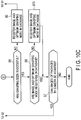
- FIGS. 10A to 10C The flowcharts shown in FIGS. 10A to 10C will be described.
- the flowcharts shown in FIGS. 10A to 10C are continuous. Note that, herein, the placement portion 12 on which the packages B1, B2, B3 and so on are placed is disposed at a predetermined position with respect to the conveyance apparatus 22.
- the controller 32 disposes the arm 36, the grip 38 and the lower support 40 at the initial positions.
- the initial positions are positions that do not obstruct the camera 34 to photograph the packages B1, B2 and so on, on the placement portion 12.
- the controller 32 acquires the image information on the packages B1, B2 and so on captured by the camera 34 (Step S1). In a case where the image information on the packages B1, B2 and so on could not be acquired, the processing is repeated until the image information can be obtained.
- the controller 32 determines, for example, that the package B1 on the frontmost upper side is a grasping target in the package determinator 54 by using a known technique, and the controller 32 searches whether or not the package image information 42a for the package B1 acquired by the camera 34 and the grasping mode information 42b for that package B1 are in the database 42 (Step S2). In a case where the package image information 42a for the package B1 acquired by the camera 34 and the grasping mode information 42b are in the database 42 (Yes in Step S2), the controller 32 selects a grasping mode by the grasping mode information 42b for that package B1 (Step S3).
- the controller 32 determines the sizes of the one or more packages B1, B2, B3 and so on and the availability of suction and determines which one of the upper face, the front face and the back face of the selected package B1 should be grasped.
- the controller 32 causes the movement mechanism 44, the arm 36, the lower support 40 and the grip 38 to operate based on the grasping mode for that package B1 selected from the frictional grasping/the suction grasping/the back face grasping (Step S4). Note that there may be a case where the movement of the movement mechanism 44 is unnecessary.
- Step S4 while the package B1 is supported by the lower support 40, the grip 38 grasps the package B1 as appropriate as well as the arm 36, the grip 38, the lower support 40 and the movement mechanism 44 are operated to place the package B1 on the conveyor 24.
- the controller 32 determines whether or not the grip 38 has successfully grasped the package B1 (Step S5). When it has been determined that the grip 38 has successfully grasped that package B1 (Yes in Step S5), the controller 32 determines whether the image information and the optimum grasping mode are registered in the database 42 (Step S6). When is has been determined that the package image information 42a and the optimum grasping mode information 42b are registered in the database 42 (Yes in Step S6), the controller 32 ends the processing for that package B1.
- the controller 32 acquires the image information on the packages B2, B3 and so on, which are placed on one placement portion 12, captured by the camera 34 (Step S7).
- the controller 32 may end the processing for that package B1. That is, when the controller 32 has determined that the grip 38 has successfully grasped that package B1 (Yes in Step S5), the processing in Step S6 is not necessarily required since the package image information 42a and the optimum grasping mode information 42b are already registered in the database 42.
- the controller 32 determines, for example, that the package B2 on the uppermost side is a grasping target by using a known technique.
- the controller 32 searches whether the package image information 42a for the package B2 acquired by the camera 34 and the grasping mode information 42b for that package B2 are in the database 42 (Step S2). Then, according to the flow described above or according to the flow described later, the controller 32 performs processing of grasping the package B2 to be conveyed onto the conveyor 24.
- the controller 32 determines that no packages are present on that placement portion 12, and ends the processing of placing the packages, which are placed on one placement portion 12, onto the conveyor 24.
- the controller 32 determines whether or not the grip 38 has successfully grasped the package B1
- various sensors provided at the grip 38 are used.
- the controller 32 determines that the grasping of the package B1 has failed.
- the controller 32 determines whether there is a flat face on the upper face of that package B1 from the image information acquired by the camera 34.
- Step S11 When the controller 32 has determined that that package B1 does not have a flat face and that package B1 has a shape different from a box shape (No in Step S11), the package B1 cannot be subjected to the frictional grasping or the suction grasping. That is, since that package B1 cannot be subjected to the upper face grasping shown in FIG. 4A or the front face grasping shown in FIG. 4B , the back face grasping (Step S12) shown in FIG. 4C is selected.
- Step S11 the controller 32 determines whether there is a label, wrapping paper or vinyl on that package B1 from the image information acquired by the camera 34 (Step S21).
- Step S21 When the controller 32 has determined that there is a label, wrapping paper or vinyl on that package B1 (Yes in Step S21), it is difficult to or impossible to perform the frictional grasping or the suction grasping for that package B1 so that the back face grasping (Step S12) is selected.
- the controller 32 determines whether the volume of the package B1 is equal to or less than a threshold V1 from the image information acquired by the camera 34 (Step S22). Note that, in addition to the threshold V1 of the volume of the package B1, if the package B1 has a box shape, a threshold for the sum of the three sides having a common vertex may be set as appropriate.
- Step S22 In a case where the volume of the package B1 is equal to or less than the threshold V1 (Yes in Step S22), there is a possibility that that package B1 is light. Then, since the frictional grasping can be performed faster than the suction grasping, the controller 32 selects the frictional grasping (Step S23) in a case where the volume of the package B1 is less than the threshold V1.
- the controller 32 determines whether the volume of the package B1 is equal to or less than a threshold V2 (> VI) from the image information acquired by the camera 34 (Step S31).
- Step S31 In a case where the volume of the package B1 is greater than the threshold V2 (No in Step S31), there is a possibility that the package B1 is heavy. In a case where the package B1 is heavier than a predetermined weight, the controller 32 selects the back face grasping (Step S12) since the suction grasping cannot be performed.
- the controller 32 determines that the package B1 has a weight that can be subjected to the suction grasping, and selects the suction grasping (Step S32).
- the grasping mode determinator 56 of the controller 32 selects a grasping mode according to the exterior of the package B1. That is, the controller 32 selects a grasping mode according to the package B1.
- the controller 32 determines the sizes of the one or more packages B1, B2, B3 and so on and the availability of suction and determines which one of the upper face, the front face and the back face of the selected package B1 should be grasped.
- the selection of the grasping mode at this time is first determination.
- the controller 32 After the first optimum grasping mode is determined by the grasping mode determinator 56, the controller 32 transmits and receives signals to and from the arm 36, the grip 38 and the lower support 40 as shown in FIG. 10B to perform the grip control.
- Step S23 the controller 32 determines whether the frictional grasping is possible by the pads or the like for upper face of the package B1 from the size and exterior of the package B1 (Step S41). When the frictional grasping is possible (Yes in Step S41), the controller 32 selects the upper face frictional grasping (Step S42).
- the controller 32 determines whether the two-face frictional grasping is possible based on the size of the package B1 (Step S43).
- the two-face frictional grasping is a mode of grasping both the upper face and the front face of that package B1 with the pads or the like. Then, when it has been determined that the two-face frictional grasping is possible for that package B1 (Yes in Step S43), the controller 32 selects the two-face frictional grasping (Step S44). Then, the controller 32 transmits and receives signals to and from the arm 36, the grip 38 and the lower support 40 and causes them to operate as appropriate (Step S4).
- the controller 32 When the controller 32 has determined that the upper face frictional grasping and the two-face frictional grasping are not possible for that package B1 (No in Step S43), the controller 32 switches the grasping mode for that package B1 from the frictional grasping (Step S23) to the suction grasping (Step S32).
- Step S32 the controller 32 determines whether the upper face suction grasping is possible based on the size and exterior of the package B1 (Step S51). When it has been determined that the upper face suction grasping is possible for that package B1 (Yes in Step S51), the controller 32 selects the upper face suction grasping (Step S52). That is, the controller 32 transmits and receives signals to and from the arm 36, the grip 38 and the lower support 40 and causes them to operate as appropriate (Step S4).
- the controller 32 determines whether the front face suction grasping is possible for that package B1 based on the size and exterior of that package B1 (Step S53) .
- Step S53 the controller 32 selects the front face suction grasping (Step S54). Then, the controller 32 transmits and receives signals to and from the arm 36, the grip 38 and the lower support 40 and causes them to operate as appropriate (Step S4).
- the controller 32 determines whether the two-face suction grasping is possible for that package B1 based on the size and exterior of that package B1 (Step S55) .
- Step S55 the controller 32 selects the two-face suction grasping (Step S56). Then, the controller 32 transmits and receives signals to and from the arm 36, the grip 38 and the lower support 40 and causes them to operate as appropriate (Step S4) .
- Step S51 When the controller 32 has determined that the upper face suction grasping (Step S51), the front face suction grasping (Step S53) and the two-face suction grasping (Step S55) are not possible for that package B1 (No in Step S55), the controller 32 switches the grasping mode for that package B1 from the suction grasping (Step S32) to the back face grasping (Step S12).
- the controller 32 determines whether the gap G between the back face of the package B1 and the front face of the package B2 is equal to or greater than the threshold d1 (Step S61).
- the controller 32 performs the gap generation operation by the suction grasping or the frictional grasping as shown in FIG. 9A (Step S62). Thereafter, the controller 32 detects the gap G from the image information acquired by the camera 34 again.
- the controller 32 further determines whether the gap is equal to or greater than a threshold d2 (> d1) (Step S63) .
- Step S63 In a case where the controller 32 has determined that the gap G is greater than the threshold d2 (Yes in Step S63), the gap search operation is unnecessary even when the detection error is taken into consideration, and the back face grasping is directly selected (Step S64).
- the controller 32 determines any one or a plurality of the upper face, the front face and the back face of the one or more packages B1 to be grasped based on the image information photographed by the camera 34 and the information in the database 42.
- the controller 32 transmits and receives signals to and from the arm 36, the grip 38 and the lower support 40 and causes them to operate as appropriate (Step S4).
- the controller 32 moves the back face grip 68 of the grip 38 as appropriate to perform the gap search operation in order to cope with a case where the detected position is shifted from the actual position due to a detection error or the like (Step S65). Then, the controller 32 detects the accurate position of the gap G between the packages B1 and B2, transmits and receives signals to and from the arm 36, the grip 38 and the lower support 40, causes them to operate as appropriate, and selects the back face grasping for the package B1 (Step S4).
- the controller 32 transmits and receives signals to and from the arm 36, the grip 38 and the lower support 40, causes them to operate as appropriate, and grasps the package B1 with an appropriate mode. Then, the package B1 is placed on the conveyor 24.
- the grip 38 and the lower support 40 are separated from the front face of the package B3. At this time, images of the packages B2, B3, B4 are acquired again by the camera 34 after the package B1 has been removed. Thereafter, the grip 38 and the lower support 40 return to the initial positions with respect to the placement portion 12.
- the controller 32 detects whether or not the graspingS by the grip 38 has been successful (Step S5). When the controller 32 has determined that the grasping by the grip 38 has been successful, it is determined whether the image information on the package B1 and the optimum grasping mode are registered in the database 42 (Step S6). When they are registered (Yes in Step S6), the processing ends. When they are not registered (No in Step S6), the image information on the package B1 and the optimum grasping mode are registered in the database 42 (Step S70).
- the controller 32 registers the image information on the package B1 and the information on the improper grasping mode in the database 42 (Step S80). Then, the controller 32 determines again a package to be grasped from among the packages B1, B2, B3 and so on. The controller 32 acquires the image information on the grasping package B1 by the camera 34 (Step S1) and performs again the series of processing shown in FIGS. 10A to 10C .
- the controller 32 determines the size of that package B1 and the availability of suction and determines again which one of the upper face, the front face and the back face of that package B1 should be grasped.
- the weight of the package B1 can be estimated since the grip 38 has tried to grasp the package B1.
- the frictional grasping (Step S23), the suction grasping (Step S32) or the back face grasping (Step S12) is selected as appropriate in conjunction with the weight data of the package B1.
- Step S23 when the controller 32 selected the frictional grasping (Step S23) and determined that the upper face frictional grasping is possible (Yes in Step S41) in the first processing when the grasping of that package B1 failed, it can be determined that the upper face frictional grasping is not possible (No in Step S41) in the next processing by the improper grasping mode registered in the database 42 together with the weight data of that package B1 as determination basis.
- the controller 32 may select the two-face frictional grasping for the package B1, determine that the suction grasping is performed instead of selecting the two-face frictional grasping, or determine that the back face grasping is performed for the package B1.
- the controller 32 may select the two-face suction grasping for the package B1 or determine that the back face grasping is performed instead of selecting the two-face suction grasping.
- the controller 32 controls the arm 36, the grip 38 and the lower support 40 to, for example, place the package B1 on the conveyor 24.
- the conveyor 24 conveys the package B1 placed thereon toward a predetermined position.
- the controller 32 selects the next package B2 and likewise controls the arm 36, the grip 38 and the lower support 40 to perform the work of grasping the next package B2.
- the controller 32 In a case where the grasping of that package B1 has failed a plurality of times, for example, two or more times such as three times or four times, the controller 32 outputs an error and stops the arm 36, the grip 38 and the lower support 40.
- the number of failures until the arm 36, the grip 38 and the lower support 40 of the conveyance apparatus 22 are stopped when the grip 38 had tried to grasp the same package B1 is suitably plural, but the number can be set as appropriate.
- the controller 32 can suppress the failure in next grasping by selecting and executing the back face grasping for that package B1. Then, the operation of the conveyance apparatus 22 is continued so that the processing of the packages B1, B2 and so on can be continued.
- the packages B1, B2, B3 and so on can be removed from the placement portion 12 and placed on the conveyor 24 in an appropriate removal order.
- the placement portion 12 should be disposed at a position facing the unloading system 10 (the conveyance apparatus 22). Thus, it is unnecessary to arrange part of the unloading system 10 (the conveyance apparatus 22) on the back face side of the placement portion 12.
- the frictional grasping with the fastest processing speed for one package is a first option
- the next fast suction grasping is a second option
- the back face grasping is a third option at last.
- the controller 32 can select the frictional grasping, the suction grasping and the back face grasping as appropriate according to the packages B1, B2 and so on.
- the processing of placing all the packages, which are placed on the placement portion 12, on the conveyor 24 can be performed more efficiently than performing one grasping method, for example, the suction grasping or the like, for all the packages. Therefore, it is possible to shorten the time to place all the packages on the conveyor 24 from one placement portion 12.
- the first example can provide a conveyance apparatus, a conveyance system and a conveyance method, which can automatically determine grasping mode of one or more packages and execute grasping.
- the failure in the grasping can be suppressed by making the upper face frictional grasping/the two-face frictional grasping as options according to the states of the packages.
- the failure in the grasping can be suppressed by making the upper face suction grasping/the front face suction grasping/the two-face suction grasping as options according to the states of the packages.
- the failure in the grasping can be suppressed by forming a gap between the packages according to the mutual states of the packages. Therefore, by using the conveyance apparatus 22 of the system 10 according to the present example, it is possible to suppress the failure to grasp each package.
- the example has been described in which the package B2 is present on the back face side of the package B1. Even when the package B2 is not present on the back face side of the package B1, the package B1 can be grasped by the grip 38 while being supported by the lower support 40 as described above, and that package B1 can be placed on the conveyor 24. Thus, the space or the wall of the placement portion 12 may be present on the back face side of the package B1.
- a first modification example is a further modification example of the first example.
- the conveyance system further includes a controller (processor)including a communicator.
- the controller (processor) is configured to control the communicator, and access a database through the communicator in which information on the one or more packages is stored.
- the controller (processor) is configured to determine which (one of) grasping mode of frictional grasping, suction grasping and back face grasping should be selected based on the image information photographed by the camera and the information in the database, is configured to move the arm and the grip based on the determination, and take out the one or more packages from the placement portion while at least one of the one or more packages is grasped by the grip by moving the arm and the grip.
- a system 10 has a conveyance apparatus 22 and a server 90.
- the conveyance apparatus 22 has a controller 32, a camera 34, an arm 36, a grip 38, a lower support 40 and a movement mechanism 44.
- the controller 32 includes a communicator 58.
- the controller 32 is configured to control the communicator 58.
- the communication by the communicator 58 may be wired or wireless.
- the communicator 58 can access a database 42 stored on the server 90 via a network.
- the conveyance apparatus 22 of the present modification example does not include the database 42 of the server 90.
- the controller 32 can read out data (information) stored in the database 42. Moreover, by being communicated by the communicator 58, the controller 32 can store data (information) in the database 42 as appropriate.
- the system 10 can connect a plurality of conveyance apparatuses 22 at not only one location but also a large number of locations to the network to share package image information 42a and grasping mode information 42b.
- the image information (package image information) 42a on a predetermined package and the grasping mode information 42b corresponding to the predetermined package image information 42a on a one-to-one basis are stored.
- the probability from Step S2 to Step S3 can be gradually increased.
- Step S4 in which the arm 36, the grip 38 and the lower support 40 are moved more efficiently.
- frictional grasping with the fastest processing speed for one package is a first option
- the next fast suction grasping is a second option
- back face grasping is a third option at last.
- the controller 32 can select the frictional grasping, the suction grasping and the back face grasping as appropriate according to the packages B1, B2 and so on.
- the failure in the grasping can be suppressed by making upper face frictional grasping/two-face frictional grasping as options according to the states of the packages.
- the failure in the grasping can be suppressed by making upper face suction grasping/front face suction grasping/two-face suction grasping as options according to the states of the packages.
- the failure in the grasping can be suppressed by forming a gap between the packages according to the mutual states of the packages. Therefore, by using the system 10 according to the present modification example, it is possible to suppress the failure to grasp each package.
- a second modification example is a further modification example of the first modification example.
- the controller (processor) of the conveyance system is configured to control the communicator, and access a database on a server through the communicator.
- the controller (processor) is configured to move the arm and the grip based on a result determined on the server as to which grasping mode of frictional grasping, suction grasping and back face grasping should be selected from the image information photographed by the camera and information in the database, and is configured to take out the one or more packages from the placement portion by moving the arm and the grip while at least one of the one or more packages is grasped by the grip.
- a system 10 has a conveyance apparatus 22 and a server 90.
- the server 90 can be used as a controller different from a controller 32 of the conveyance apparatus 22.
- the conveyance apparatus 22 has a controller 32, a camera 34, an arm 36, a grip 38, a lower support 40 and a movement mechanism 44.
- the controller 32 includes a communicator 58.
- the controller 32 is configured to control the communicator 58.
- the communication by the communicator 58 may be wired or wireless.
- the communicator 58 can access a database 42 stored in the server 90 via a network.
- the conveyance apparatus 22 of the present modification example does not include the database 42 of the server 90.
- a program (a package determinator 54) that determines a package to be grasped from among packages B1, B2, B3 and so on and also a program (a grasping mode determinator 56) that determines the grasping mode for the selected package B1 are executed by the server 90, and control signals thereof are transmitted to the controller 32 via the communicator 58 to control the movements of the arm 36, the grip 38, the lower support 40 and the movement mechanism 44.
- the controller 32 of the present modification example does not include the package determinator (an image processing section) 54 and the grasping mode determinator 56. That is, in the server 90, the server (the controller) 90 determines which one of the upper face, the front face and the back face of the certain package B1 should be grasped by the grip 38 based on image information photographed by the camera 34 and information in the database 42.
- the controller 32 of the conveyance apparatus 22 receives the determination result by the server 90 as to which one of the upper face, the front face and the back face of the package B1 is to be grasped.
- the controller 32 (a grip controller 52) moves the arm 36, the grip 38 and the lower support 40 and takes out the package B1 from the placement portion 12 by moving the arm 36, the grip 38 and the lower support 40 while the package B1 is grasped by the grip 38 and the package B1 is supported by the lower support 40 from the lower side.
- FIG. 12 shows that the controller 32 has the grip controller 52.
- the arm 36, the grip 38 and the movement mechanism 44 may be operated by control via the communicator 58. That is, the server 90 may execute a program (the grip controller 52) that causes the arm 36, the grip 38 and the movement mechanism 44 to operate.
- a communicator may be arranged in the camera 34 to transmit the image information captured by the camera 34 directly to the server 90, not via the controller 32.
- the package determinator 54 of the server 90 detects which package to be grasped from among the packages B1, B2 and so on and the edges of the packages B2 and B3 adjacent to the package B1 to be grasped.
- the server 90 by the instruction of the server 90, frictional grasping with the fastest processing speed for one package is a first option, the next fast suction grasping is a second option, and back face grasping is a third option at last. Then, the server 90 can select the frictional grasping, the suction grasping and the back face grasping as appropriate according to the packages B1, B2 and so on.
- the processing of placing all the packages, which are placed on the placement portion 12, on the conveyor 24 can be performed more efficiently than performing one grasping method, for example, the suction grasping or the like, for all the packages. Therefore, it is possible to shorten the time to place all the packages on the conveyor 24 from one placement portion 12.
- the failure in the grasping can be suppressed by making upper face frictional grasping/two-face frictional grasping as options according to the states of the packages.
- the failure in the grasping can be suppressed by making upper face suction grasping/front face suction grasping/two-face suction grasping as options according to the states of the packages.
- the failure in the grasping can be suppressed by forming a gap between the packages according to the mutual states of the packages. Therefore, by using the system 10 according to the present modification example, it is possible to suppress the failure to grasp each package.
- the present example is a further modification example of the first example including each modification example.
- An objective according to the second example is to provide a conveyance apparatus, a conveyance system and a conveyance method, which can automatically determine a grasping method of one or more packages and execute grasping.
- a grip 38 can grasp one or more packages in a case of performing back face grasping.
- the grip 38 can grasp at least one of one or more packages.
- An arm 36 moves the grip 38 in the positive X-axis direction toward one or more packages imaged by one or more cameras 34 as well as moves the grip 38 in the negative X-axis direction from a placement portion 12 to be retracted in a state where the one or more packages are grasped by the grip 38.
- a lower support 40 takes out the one or more packages from the placement portion 12 while supporting the one or more packages, which are moved by the grip 38, from the lower side.
- a controller 32 can determine, by using images obtained from the one or more cameras 34, whether or not a plurality of packages B11, B12, B13, B21, B22 and B23 can be simultaneously placed on the lower support 40 with a known technique.
- FIG. 13 shows a state where the plurality (herein, six) of packages B11, B12, B13, B21, B22 and B23 are moved with respect to packages B31, B32, B41 and so on by the back face grasping of the grip 38 and are about to be put on the lower support 40.
- a back face grip 68 of the grip 38 has an appropriate width, for example, narrower than the horizontal width of the placement portion 12 along the Y-axis direction.
- the back face grip 68 has a plurality of claws 69a, 69b and so on deformed as appropriate. Note that, for example, the claws 68a, 68b, 72b, 74c, 78a, 78b and 78c shown in FIGS. 3A and 3B , FIGS. 7A and 7B and FIGS. 8A and 8B are applied to the claws 69a, 69b and so on as appropriate.
- the grip 38 suitably not only has the back face grip 68 but also has an upper face grip 64 and a front face grip 66 described in the first example.
- the box-shaped packages B31, B32, B41 and so on are stacked on the upper faces of box-shaped packages B51, B52, B61 and so on.
- the heights of the box-shaped packages B31, B32, B41 and so on in the Z-axis direction are substantially the same.
- each of the packages B11, B12, B13, B21, B22 and B23 is placed on the upper faces of the packages B31, B32, B41 and so on with substantially the same heights in the Z-axis direction.
- a package determinator 54 of the controller 32 determines that each of the packages B11, B12, B13, B21, B22 and B23 is placed on the upper faces of the packages B31, B32, B41 and so on at positions substantially the same in the Z-axis direction. At this time, the packages B11, B12 and B13 are disposed on the front side, and the packages B21, B22 and B23 are disposed on the back side.
- each of the packages B11, B12, B13, B21, B22 and B23 is not limited to a box shape (rectangular parallelepiped), and various shapes such as a paper bag, an envelope and a columnar shape are allowed.
- the packages B31, B32, B41 and so on and B51, B52, B61 and so on are also not necessarily a box shape.
- the package determinator 54 of the controller 32 detects the lower edges of the packages B11, B12 and B13 by image information from the camera 34.
- the controller 32 (or a server 90) has determined that the packages B11, B12, B13, B21, B22 and B23 are simultaneously put on the lower support 40.
- a grip controller 52 of the controller 32 moves the lower support 40 in the positive X-axis direction and makes the lower support 40 near or abut the front faces of the packages B31 and B32 slightly under the lower edges of the packages B11, B12 and B13.
- the grip controller 52 of the controller 32 makes the tip of the lower support 40 near the lower edges of the front faces of the packages B11, B12 and B13 removed from the placement portion 12 as well as disposes the tip slightly under the lower edges of the front faces of the packages B11, B12 and B13.
- the grip controller 52 of the controller 32 disposes the back face grip 68 of the grip 38 on the back face sides of the packages B21, B22 and B23. Then, the controller 32 disposes the claws 69a, 69b and so on of the back face grip 68 on the back face sides of the packages B21, B22 and B23.
- the controller 32 causes the grip 38 (the back face grip 68) to operate in the negative X-axis direction in a state where the lower support 40 is made near or abut the front faces of the packages B31 and B32.
- those packages B11, B12, B13, B21, B22 and B23 are drawn in the negative X-axis direction with respect to the packages B31, B32, B41 and so on under the packages B11, B12, B13, B21, B22 and B23.
- the packages B11, B12, B13, B21, B22 and B23 are taken out from the placement portion 12 in the negative X-axis direction and put on the lower support 40.
- the grip controller 52 of the controller 32 puts the packages B11, B12, B13, B21, B22 and B23 on a conveyor 24.
- the back face grasping can be a first option unlike the first example where the packages B1, B2 and so on are grasped one by one and supported by the lower support 40.
- an unloading system 10 (a conveyance apparatus 22) can combine as appropriate a mode of selecting packages one by one with the controller 32 (or the server 90) to be removed from the placement portion 12, which has been described in the first example including each modification example, and a mode of simultaneously selecting the plurality of packages with the controller 32 (or the server 90) to be removed from the placement portion 12, which has been described in the present example.
- the second example can provide a conveyance apparatus, a conveyance system and a conveyance method, which can automatically determine grasping mode of one or more packages and execute grasping.
- a lower support 40 has a plurality of lower support plates 40a, 40b and 40c.
- the number of lower support plates 40a, 40b and 40c is three herein, but may be more.
- the width of each of the lower support plates 40a, 40b and 40c along the Y-axis direction is set to be the width substantially the same as the size of the package, which is presumed to be the minimum size.
- the width of each of the lower support plates 40a, 40b and 40c along the Y-axis direction can be set as appropriate.
- a grip controller 52 of a controller 32 can independently move each of the lower support plates 40a, 40b and 40c in the positive X-axis direction and the negative X-axis direction.
- the grip controller 52 of the controller 32 can move each of the lower support plates 40a, 40b and 40c together in the same direction in the positive Y-axis direction and the negative Y-axis direction. In this manner, each of the lower support plates 40a, 40b and 40c is independently driven in the forward direction (the positive X-axis direction) heading toward a placement portion 12 and in the backward direction (the negative X-axis direction) retracting from the placement portion 12 by signals from the controller 32.
- the grip controller 52 of the controller 32 can suitably independently move each of the lower support plates 40a, 40b and 40c in the positive Z-axis direction and the negative Z-axis direction.
- each of the lower support plates 40a, 40b and 40c can be independently driven in the upward direction (the positive Z-axis direction) and in the downward direction (the negative Z-axis direction) by signals from the controller 32.
- a package determinator 54 of the controller 32 detects the lower edges of packages B12, B13 and B21.
- the grip controller 52 of the controller 32 makes the lower support 40 near or abut the front faces of packages B31, B32 and B41 slightly under the lower edges of the packages B12, B13 and B21.
- the tip of the lower support plate 40a is made near or abut the front face of the package B41 slightly under the lower edge of the package B21.
- the tip of the lower support plate 40b is made near or abut the front face of the package B31 slightly under the lower edge of the package B12.
- the tip of the lower support plate 40c is made near or abut the front face of the package B31 slightly under the lower edge of the package B13.
- the controller 32 disposes claws 69a, 69b and so on of a back face grip 68 of a grip 38 at the back faces of packages B21, B22 and B23 in a state where the lower support plate 40a is made near or abut the front face of the package B41 and the lower support plates 40b and 40c are made near or abut the front face of the package B31.
- the controller 32 causes the grip 38 to operate in the negative X-axis direction to draw the packages B12, B13, B21, B22 and B23 in the negative X-axis direction with respect to the packages B31, B41 and so on.
- the package B21 is put on the lower support plate 40a.
- the packages B12 and B22 are put on the lower support plate 40b.
- the packages B13 and B23 are put on the lower support plate 40c.
- the plurality of packages B12, B13, B21, B22 and B23 are simultaneously placed on a conveyor 24.
- the lower support 40 By forming the lower support 40 divided into the plurality of lower support plates 40a, 40b and 40c, even in a case where the position of the front face of each of the packages is shifted in the X-axis direction, it is possible to simultaneously put the packages on the conveyor 24.
- the back face grasping depending on the number of packages processed simultaneously, for example, the five packages B12, B13, B21, B22 and B23, or the like, it is possible to improve the conveyance speeds of the packages as a whole as compared with a case where frictional grasping or suction grasping is performed for each package.
- a back face grip 68 has rods 76a, 76b and 76c which can expand and contract along the X-axis direction, and claws 78a, 78b and 78c at the tips of the rods 76a, 76b and 76c.
- the plurality of rods 76a, 76b and 76c are provided at the tip portion of a base 62 of a grip 38.
- the positions of the claws 78a, 78b and 78c along the X-axis direction are independently adjusted by the expansion and contraction of the rods 76a, 76b and 76c, respectively.
- this back face grip 68 can independently move the plurality of claws 78a, 78b and 78c with respect to the back face of one or more packages.
- the claw 78a with respect to the rod 76a can be suitably deformed between an initial shape and a deformation state as in the examples shown in FIGS. 7A and 7B or the examples shown in FIGS. 8A and 8B .
- the claw 78b with respect to the rod 76b and the claw 78c with respect to the rod 76c can be suitably deformed between an initial shape and a deformation state.
- the rods 76a, 76b and 76c are provided in a state of protruding from the tip of the base 62.
- these rods can suitably expand and contract, but at least two of the rods should be able to expand and contract.
- the number of rods is two, these rods can suitably expand and contract, but at least one of the rods should be able to expand and contract.
- the examples shown in FIGS. 13 and 14 the examples have been described in which the claws of the back face grip 68 are on one plane parallel to the YZ plane.
- the claws 78a and 78b of the back face grip 68 at least two of the rods 76a, 76b and 76c move along the X-axis direction.
- the claws 78a, 78b and 78c may be on one plane parallel to the YZ plane, but they may be separately disposed on two planes parallel to the YZ plane or on three planes parallel to YZ plane.
- FIG. 16 a description will be given of a case where such a back face grip 68 has three rods 76a, 76b and 76c and the claws 78a, 78b and 78c.
- the position of the back face of a package B21 and the position of the back face of a package B22 are greatly shifted along the X-axis direction. There is no package present on the front face side and back face side of the package B21. There is a package B41 under the package B21.
- the upper face of the package B31 and the upper face of the package B41 are shifted in the Z-axis direction.
- a grip controller 52 of a controller 32 makes the tip of a lower support plate 40a of a lower support 40 near or abut the front face of the package B41 slightly under the lower edge of the package B21 to be grasped.
- the grip controller 52 of the controller 32 makes the tips of lower support plates 40b and 40c of the lower support 40 near or abut the front face of the package B31 slightly under the lower edges of the packages B12 and B13 to be grasped.
- the controller 32 disposes the claws 78a, 78b and 78c of the back face grip 68 of the grip 38 at the back faces of the packages B21 and B22 in a state where the lower support plates 40a and 40b are made near or abut the front face of the package B31 and the lower support plate 40c is made near or abut the front face of the package B41.
- the controller 32 causes the grip 38 to operate in the negative X-axis direction to draw the package B21 in the negative X-axis direction with respect to the package B41 as well as to draw the packages B12, B13 and B22 in the negative X-axis direction with respect to the package B31.
- the package B21 is put on the lower support plate 40a.
- the package B12 is put on the lower support plate 40b.
- the package B13 is put on the lower support plate 40c.
- the package B22 is put on the lower support plates 40b and 40c.
- the plurality of packages with the front faces not aligned not only in the X-axis direction but also in the Z-axis direction can be simultaneously put on the lower support 40.
- the plurality of packages with the respective back faces not aligned in the X-axis direction can be simultaneously put on the lower support 40.
- the present disclosure also encompasses the following examples of a conveyance apparatus, a conveyance system and a conveyance method:
Landscapes
- Engineering & Computer Science (AREA)
- Mechanical Engineering (AREA)
- Robotics (AREA)
- General Engineering & Computer Science (AREA)
- Orthopedic Medicine & Surgery (AREA)
- General Health & Medical Sciences (AREA)
- Health & Medical Sciences (AREA)
- Manufacturing & Machinery (AREA)
- Quality & Reliability (AREA)
- Physics & Mathematics (AREA)
- General Physics & Mathematics (AREA)
- Automation & Control Theory (AREA)
- Manipulator (AREA)
- De-Stacking Of Articles (AREA)
Applications Claiming Priority (1)
| Application Number | Priority Date | Filing Date | Title |
|---|---|---|---|
| JP2018169587A JP7068113B2 (ja) | 2018-09-11 | 2018-09-11 | 搬送装置、搬送システム及び搬送方法 |
Publications (2)
| Publication Number | Publication Date |
|---|---|
| EP3623324A1 true EP3623324A1 (de) | 2020-03-18 |
| EP3623324B1 EP3623324B1 (de) | 2023-09-06 |
Family
ID=65635447
Family Applications (1)
| Application Number | Title | Priority Date | Filing Date |
|---|---|---|---|
| EP19159667.5A Active EP3623324B1 (de) | 2018-09-11 | 2019-02-27 | Fördervorrichtung, fördersystem und förderverfahren |
Country Status (2)
| Country | Link |
|---|---|
| EP (1) | EP3623324B1 (de) |
| JP (1) | JP7068113B2 (de) |
Cited By (20)
| Publication number | Priority date | Publication date | Assignee | Title |
|---|---|---|---|---|
| CN112025701A (zh) * | 2020-08-11 | 2020-12-04 | 浙江大华技术股份有限公司 | 抓取物体的方法、装置、计算设备和存储介质 |
| EP3789325A1 (de) * | 2019-09-06 | 2021-03-10 | Kabushiki Kaisha Toshiba | Haltevorrichtung, artikelhandhabungsvorrichtung und steuerungsvorrichtung |
| CN113635330A (zh) * | 2021-07-09 | 2021-11-12 | 上海大学 | 一种刚柔耦合的爪刺抓附装置 |
| CN114455335A (zh) * | 2021-08-27 | 2022-05-10 | 西门子工业自动化产品(成都)有限公司 | 叠放箱体的分离装置和方法 |
| CN114535143A (zh) * | 2022-01-27 | 2022-05-27 | 阿丘机器人科技(苏州)有限公司 | 物流货物拣选方法、装置、设备及存储介质 |
| EP4029814A1 (de) * | 2021-01-14 | 2022-07-20 | Kabushiki Kaisha Toshiba | Haltevorrichtung, frachtumschlagsvorrichtung und halteverfahren |
| US20220297312A1 (en) * | 2021-03-18 | 2022-09-22 | Dexterity, Inc. | Multi-mode robotic end effector |
| WO2022221433A1 (en) | 2021-04-16 | 2022-10-20 | Mujin, Inc. | Robotic multi-surface gripper assemblies and methods for operating the same |
| US20230099160A1 (en) * | 2021-09-24 | 2023-03-30 | Ford Global Technologies, Llc | Retention assembly for a delivery vehicle |
| WO2023059828A1 (en) * | 2021-10-06 | 2023-04-13 | Berkshire Grey Operating Company, Inc. | Systems and methods for dynamic processing of objects provided in vehicles with dual function end effector tools |
| EP4245476A1 (de) * | 2022-03-18 | 2023-09-20 | Kabushiki Kaisha Toshiba | Frachtabfertigungsvorrichtung, frachtabfertigungsverfahren und computerprogrammprodukt zur frachtabfertigung |
| US11866269B2 (en) | 2021-10-06 | 2024-01-09 | Berkshire Grey Operating Company, Inc. | Dynamic processing of objects provided in elevated vehicles with evacuation systems and methods for receiving objects |
| WO2024019945A1 (en) * | 2022-07-18 | 2024-01-25 | Dexterity, Inc. | Robotic gripper with support structure |
| US11884495B2 (en) | 2016-12-09 | 2024-01-30 | Berkshire Grey Operating Company, Inc. | Systems and methods for processing objects provided in vehicles |
| CN117533689A (zh) * | 2024-01-09 | 2024-02-09 | 山西怡顺行冷链物流有限公司 | 一种冷链物流仓储用箱式货物堆码装置 |
| WO2023235911A3 (de) * | 2022-06-08 | 2024-03-14 | Tgw Logistics Group Gmbh | Transfervorrichtung und verfahren zum handhaben von packeinheiten |
| WO2024239106A1 (en) * | 2023-05-19 | 2024-11-28 | Nexera Robotics Corp. | System and method to augment grasping of objects via an auxilary grasping device |
| US20250114950A1 (en) * | 2023-10-06 | 2025-04-10 | Symbotic Llc | Tool, depalletizer including the tool, and method for depalletizing mixed load products |
| EP4571614A1 (de) * | 2023-12-13 | 2025-06-18 | Körber Supply Chain Logistics GmbH | Verfahren zum handhaben eines stückguts |
| WO2025188969A1 (en) * | 2024-03-08 | 2025-09-12 | Contoro Inc. | Articulated multi-zone robot end effector systems and methods for high moment loads |
Families Citing this family (8)
| Publication number | Priority date | Publication date | Assignee | Title |
|---|---|---|---|---|
| JP7261069B2 (ja) * | 2019-04-09 | 2023-04-19 | 川崎重工業株式会社 | ロボットハンド、ロボット及びロボットシステム |
| US12589508B2 (en) | 2019-08-05 | 2026-03-31 | Kawasaki Jukogyo Kabushiki Kaisha | Robot hand, robot, robot system, and transfer method |
| JP7481977B2 (ja) * | 2020-09-17 | 2024-05-13 | 株式会社東芝 | 制御装置、制御方法、及び荷役システム |
| CN113682813B (zh) * | 2021-08-31 | 2023-03-24 | 山东爱通代代良智能科技有限公司 | 冷链集装箱纸箱货物装卸夹具及方法 |
| JP7681939B2 (ja) * | 2021-09-03 | 2025-05-23 | 西部電機株式会社 | かご台車への荷物積載装置 |
| JP7824784B2 (ja) * | 2022-02-15 | 2026-03-05 | 三星電子株式会社 | ロボットハンドおよびロボット |
| JP7559794B2 (ja) * | 2022-03-29 | 2024-10-02 | 株式会社ダイフク | 荷卸し装置 |
| JP2025027540A (ja) * | 2023-08-15 | 2025-02-28 | 三菱重工業株式会社 | 把持装置および方法 |
Citations (6)
| Publication number | Priority date | Publication date | Assignee | Title |
|---|---|---|---|---|
| US20070280812A1 (en) * | 2006-05-17 | 2007-12-06 | Axium Inc. | Tool and method for mixed palletizing/depalletizing |
| WO2015132720A1 (en) * | 2014-03-04 | 2015-09-11 | Sir S.P.A. | Gripper with movable jaw and suction device |
| US20150314972A1 (en) * | 2012-12-04 | 2015-11-05 | Copal Development B.V. | A Device For Handling Stackable Cargo Units In A Cargo Space, As Well As A Method For Handling Stackable Cargo Units |
| US20170137236A1 (en) * | 2015-11-13 | 2017-05-18 | Kabushiki Kaisha Toshiba | Transporting apparatus and transporting method |
| WO2017181337A1 (en) * | 2016-04-19 | 2017-10-26 | Abb Schweiz Ag | A gripping device, a de-palletizing system, a gripping method and a de-palletizing method |
| US20180079082A1 (en) * | 2016-09-20 | 2018-03-22 | Kabushiki Kaisha Toshiba | Robot hand device and carrier apparatus using the robot hand device |
Family Cites Families (5)
| Publication number | Priority date | Publication date | Assignee | Title |
|---|---|---|---|---|
| JPH063588U (ja) * | 1992-06-23 | 1994-01-18 | 積水化学工業株式会社 | 物品把持ハンド |
| JPH10120187A (ja) * | 1996-10-23 | 1998-05-12 | Murata Mach Ltd | 物品取上げ装置 |
| JP4655309B2 (ja) | 2005-11-09 | 2011-03-23 | 株式会社Ihi | ピッキング順序決定方法、装置及びそのプログラム、並びにピッキングシステム |
| JP6710622B2 (ja) | 2015-11-13 | 2020-06-17 | 株式会社東芝 | 搬送装置および搬送方法 |
| JP2018122945A (ja) | 2017-01-30 | 2018-08-09 | 株式会社東芝 | 可変型物品保持装置、移載装置、ロボットハンドリングシステム、および移載装置の制御方法 |
-
2018
- 2018-09-11 JP JP2018169587A patent/JP7068113B2/ja active Active
-
2019
- 2019-02-27 EP EP19159667.5A patent/EP3623324B1/de active Active
Patent Citations (6)
| Publication number | Priority date | Publication date | Assignee | Title |
|---|---|---|---|---|
| US20070280812A1 (en) * | 2006-05-17 | 2007-12-06 | Axium Inc. | Tool and method for mixed palletizing/depalletizing |
| US20150314972A1 (en) * | 2012-12-04 | 2015-11-05 | Copal Development B.V. | A Device For Handling Stackable Cargo Units In A Cargo Space, As Well As A Method For Handling Stackable Cargo Units |
| WO2015132720A1 (en) * | 2014-03-04 | 2015-09-11 | Sir S.P.A. | Gripper with movable jaw and suction device |
| US20170137236A1 (en) * | 2015-11-13 | 2017-05-18 | Kabushiki Kaisha Toshiba | Transporting apparatus and transporting method |
| WO2017181337A1 (en) * | 2016-04-19 | 2017-10-26 | Abb Schweiz Ag | A gripping device, a de-palletizing system, a gripping method and a de-palletizing method |
| US20180079082A1 (en) * | 2016-09-20 | 2018-03-22 | Kabushiki Kaisha Toshiba | Robot hand device and carrier apparatus using the robot hand device |
Non-Patent Citations (1)
| Title |
|---|
| AYDIN K K ED - DE SARIO M ET AL: "FUZZY REPRESENTATION OF GRASPING MODES", MELECON '96. 8TH. MEDITERRANEAN ELECTROTECHNICAL CONFERENCE. INDUSTRIAL APPLICATIONS IN POWER SYSTEMS, COMPUTER SCIENCE AND TELECOMMUNICATIONS. BARI, IT., MAY 13 - 16, 1996; [MELECON. MEDITERRANEAN ELECTROTECHNICAL CONFERENCE], NEW YORK, IEEE, US, vol. CONF. 8, 13 May 1996 (1996-05-13), pages 182 - 185, XP000696226, ISBN: 978-0-7803-3110-5, DOI: 10.1109/MELCON.1996.550987 * |
Cited By (34)
| Publication number | Priority date | Publication date | Assignee | Title |
|---|---|---|---|---|
| US11884495B2 (en) | 2016-12-09 | 2024-01-30 | Berkshire Grey Operating Company, Inc. | Systems and methods for processing objects provided in vehicles |
| US12180014B2 (en) | 2016-12-09 | 2024-12-31 | Berkshire Grey Operating Company, Inc. | Systems and methods for processing objects provided in vehicles |
| EP3789325A1 (de) * | 2019-09-06 | 2021-03-10 | Kabushiki Kaisha Toshiba | Haltevorrichtung, artikelhandhabungsvorrichtung und steuerungsvorrichtung |
| US11014232B2 (en) | 2019-09-06 | 2021-05-25 | Kabushiki Kaisha Toshiba | Holding apparatus, article handling apparatus, and control apparatus |
| CN112025701A (zh) * | 2020-08-11 | 2020-12-04 | 浙江大华技术股份有限公司 | 抓取物体的方法、装置、计算设备和存储介质 |
| US12403614B2 (en) | 2021-01-14 | 2025-09-02 | Kabushiki Kaisha Toshiba | Holding device, cargo handling apparatus, and holding method |
| EP4029814A1 (de) * | 2021-01-14 | 2022-07-20 | Kabushiki Kaisha Toshiba | Haltevorrichtung, frachtumschlagsvorrichtung und halteverfahren |
| US20220297312A1 (en) * | 2021-03-18 | 2022-09-22 | Dexterity, Inc. | Multi-mode robotic end effector |
| WO2022197836A1 (en) * | 2021-03-18 | 2022-09-22 | Dexterity, Inc. | Multi-mode robotic end effector |
| EP4323295A4 (de) * | 2021-04-16 | 2024-11-06 | Mujin, Inc. | Robotische mehrflächengreiferanordnungen und verfahren zum betrieb davon |
| CN115744272A (zh) * | 2021-04-16 | 2023-03-07 | 牧今科技 | 机器人多表面夹持器组件及其操作方法 |
| US12421054B2 (en) | 2021-04-16 | 2025-09-23 | Mujin, Inc. | Robotic multi-surface gripper assemblies and methods for operating the same |
| WO2022221433A1 (en) | 2021-04-16 | 2022-10-20 | Mujin, Inc. | Robotic multi-surface gripper assemblies and methods for operating the same |
| CN113635330A (zh) * | 2021-07-09 | 2021-11-12 | 上海大学 | 一种刚柔耦合的爪刺抓附装置 |
| CN114455335B (zh) * | 2021-08-27 | 2024-06-07 | 西门子工业自动化产品(成都)有限公司 | 叠放箱体的分离装置和方法 |
| CN114455335A (zh) * | 2021-08-27 | 2022-05-10 | 西门子工业自动化产品(成都)有限公司 | 叠放箱体的分离装置和方法 |
| US11897546B2 (en) * | 2021-09-24 | 2024-02-13 | Ford Global Technologies, Llc | Retention assembly for a delivery vehicle |
| US20230099160A1 (en) * | 2021-09-24 | 2023-03-30 | Ford Global Technologies, Llc | Retention assembly for a delivery vehicle |
| US11866269B2 (en) | 2021-10-06 | 2024-01-09 | Berkshire Grey Operating Company, Inc. | Dynamic processing of objects provided in elevated vehicles with evacuation systems and methods for receiving objects |
| WO2023059828A1 (en) * | 2021-10-06 | 2023-04-13 | Berkshire Grey Operating Company, Inc. | Systems and methods for dynamic processing of objects provided in vehicles with dual function end effector tools |
| US12129127B2 (en) | 2021-10-06 | 2024-10-29 | Berkshire Grey Operating Company, Inc. | Dynamic processing of objects provided in elevated vehicles with evacuation systems and methods for receiving objects |
| CN114535143A (zh) * | 2022-01-27 | 2022-05-27 | 阿丘机器人科技(苏州)有限公司 | 物流货物拣选方法、装置、设备及存储介质 |
| CN116788821A (zh) * | 2022-03-18 | 2023-09-22 | 株式会社东芝 | 装卸装置、装卸方法以及计算机可读存储介质 |
| EP4245476A1 (de) * | 2022-03-18 | 2023-09-20 | Kabushiki Kaisha Toshiba | Frachtabfertigungsvorrichtung, frachtabfertigungsverfahren und computerprogrammprodukt zur frachtabfertigung |
| WO2023235911A3 (de) * | 2022-06-08 | 2024-03-14 | Tgw Logistics Group Gmbh | Transfervorrichtung und verfahren zum handhaben von packeinheiten |
| WO2024019945A1 (en) * | 2022-07-18 | 2024-01-25 | Dexterity, Inc. | Robotic gripper with support structure |
| WO2024239106A1 (en) * | 2023-05-19 | 2024-11-28 | Nexera Robotics Corp. | System and method to augment grasping of objects via an auxilary grasping device |
| US20250114950A1 (en) * | 2023-10-06 | 2025-04-10 | Symbotic Llc | Tool, depalletizer including the tool, and method for depalletizing mixed load products |
| US12605852B2 (en) * | 2023-10-06 | 2026-04-21 | Symbotic Llc | Tool, depalletizer including the tool, and method for depalletizing mixed load products |
| EP4571614A1 (de) * | 2023-12-13 | 2025-06-18 | Körber Supply Chain Logistics GmbH | Verfahren zum handhaben eines stückguts |
| DE102023134878A1 (de) * | 2023-12-13 | 2025-06-18 | Körber Supply Chain Logistics Gmbh | Verfahren zum Handhaben eines Stückguts |
| CN117533689B (zh) * | 2024-01-09 | 2024-03-22 | 山西怡顺行冷链物流有限公司 | 一种冷链物流仓储用箱式货物堆码装置 |
| CN117533689A (zh) * | 2024-01-09 | 2024-02-09 | 山西怡顺行冷链物流有限公司 | 一种冷链物流仓储用箱式货物堆码装置 |
| WO2025188969A1 (en) * | 2024-03-08 | 2025-09-12 | Contoro Inc. | Articulated multi-zone robot end effector systems and methods for high moment loads |
Also Published As
| Publication number | Publication date |
|---|---|
| EP3623324B1 (de) | 2023-09-06 |
| JP7068113B2 (ja) | 2022-05-16 |
| JP2020040788A (ja) | 2020-03-19 |
Similar Documents
| Publication | Publication Date | Title |
|---|---|---|
| EP3623324B1 (de) | Fördervorrichtung, fördersystem und förderverfahren | |
| US10222206B2 (en) | Stowage pattern calculation device which sets positions at which articles are stacked | |
| JP2015224125A (ja) | 取出装置および方法 | |
| JP7065632B2 (ja) | 箱状物ピッキング装置及びその方法 | |
| CN111328408A (zh) | 形状信息生成设备、控制设备、装卸设备、物流系统、程序和控制方法 | |
| CN107479581A (zh) | 货箱码放控制装置、系统、方法和存储介质 | |
| JP7117126B2 (ja) | ピッキング装置及びその方法 | |
| JP6917789B2 (ja) | 荷役装置、及び、荷役装置の動作方法 | |
| CN115485217B (zh) | 设定堆叠工件的位置的位置设定装置和具备位置设定装置的机器人装置 | |
| JP7042703B2 (ja) | 情報処理装置、情報処理装置を備える荷降しシステム、及び情報処理プログラム | |
| CN114762983A (zh) | 具有夹持机构的机器人系统 | |
| EP3623114A1 (de) | Entladevorrichtung und verfahren zur detektion eines pakets | |
| JP7669422B2 (ja) | 取出装置、取出方法、制御装置およびプログラム | |
| CN115703244A (zh) | 具有夹持机构的机器人系统以及相关的系统和方法 | |
| JP2016155651A (ja) | 移載装置 | |
| JP6600026B2 (ja) | 取出装置および方法 | |
| JP2022105537A (ja) | 搬送装置、搬送システム及び搬送方法 | |
| CN114896798A (zh) | 碰撞检测方法、控制方法、抓取系统及计算机存储介质 | |
| KR102303521B1 (ko) | 적재물 다중 하역 매니퓰레이터의 진동 감쇠 방법 | |
| JP2023067373A (ja) | 搬送動作生成装置、搬送動作生成方法及び移動機械システム | |
| JP2023063110A (ja) | ピッキングシステム、ピッキング装置、制御装置、プログラム、及び方法 | |
| CN114474136A (zh) | 具有夹持机构的机器人系统 | |
| JP7261597B2 (ja) | 移載対象ワーク記憶システム | |
| TW202214426A (zh) | 片材束分割把持裝置 | |
| US20260061601A1 (en) | Gripping device |
Legal Events
| Date | Code | Title | Description |
|---|---|---|---|
| PUAI | Public reference made under article 153(3) epc to a published international application that has entered the european phase |
Free format text: ORIGINAL CODE: 0009012 |
|
| STAA | Information on the status of an ep patent application or granted ep patent |
Free format text: STATUS: REQUEST FOR EXAMINATION WAS MADE |
|
| 17P | Request for examination filed |
Effective date: 20190227 |
|
| AK | Designated contracting states |
Kind code of ref document: A1 Designated state(s): AL AT BE BG CH CY CZ DE DK EE ES FI FR GB GR HR HU IE IS IT LI LT LU LV MC MK MT NL NO PL PT RO RS SE SI SK SM TR |
|
| AX | Request for extension of the european patent |
Extension state: BA ME |
|
| GRAP | Despatch of communication of intention to grant a patent |
Free format text: ORIGINAL CODE: EPIDOSNIGR1 |
|
| STAA | Information on the status of an ep patent application or granted ep patent |
Free format text: STATUS: GRANT OF PATENT IS INTENDED |
|
| INTG | Intention to grant announced |
Effective date: 20221108 |
|
| GRAJ | Information related to disapproval of communication of intention to grant by the applicant or resumption of examination proceedings by the epo deleted |
Free format text: ORIGINAL CODE: EPIDOSDIGR1 |
|
| STAA | Information on the status of an ep patent application or granted ep patent |
Free format text: STATUS: REQUEST FOR EXAMINATION WAS MADE |
|
| GRAP | Despatch of communication of intention to grant a patent |
Free format text: ORIGINAL CODE: EPIDOSNIGR1 |
|
| STAA | Information on the status of an ep patent application or granted ep patent |
Free format text: STATUS: GRANT OF PATENT IS INTENDED |
|
| INTC | Intention to grant announced (deleted) | ||
| INTG | Intention to grant announced |
Effective date: 20230329 |
|
| GRAS | Grant fee paid |
Free format text: ORIGINAL CODE: EPIDOSNIGR3 |
|
| GRAA | (expected) grant |
Free format text: ORIGINAL CODE: 0009210 |
|
| STAA | Information on the status of an ep patent application or granted ep patent |
Free format text: STATUS: THE PATENT HAS BEEN GRANTED |
|
| AK | Designated contracting states |
Kind code of ref document: B1 Designated state(s): AL AT BE BG CH CY CZ DE DK EE ES FI FR GB GR HR HU IE IS IT LI LT LU LV MC MK MT NL NO PL PT RO RS SE SI SK SM TR |
|
| RAP3 | Party data changed (applicant data changed or rights of an application transferred) |
Owner name: TOSHIBA INFRASTRUCTURE SYSTEMS & SOLUTIONS CORPORATION Owner name: KABUSHIKI KAISHA TOSHIBA |
|
| REG | Reference to a national code |
Ref country code: GB Ref legal event code: FG4D |
|
| RIN1 | Information on inventor provided before grant (corrected) |
Inventor name: SUGAHARA, ATSUSHI Inventor name: NAKAMOTO, HIDEICHI |
|
| REG | Reference to a national code |
Ref country code: CH Ref legal event code: EP |
|
| REG | Reference to a national code |
Ref country code: IE Ref legal event code: FG4D |
|
| REG | Reference to a national code |
Ref country code: DE Ref legal event code: R096 Ref document number: 602019036564 Country of ref document: DE |
|
| REG | Reference to a national code |
Ref country code: LT Ref legal event code: MG9D |
|
| REG | Reference to a national code |
Ref country code: NL Ref legal event code: MP Effective date: 20230906 |
|
| PG25 | Lapsed in a contracting state [announced via postgrant information from national office to epo] |
Ref country code: GR Free format text: LAPSE BECAUSE OF FAILURE TO SUBMIT A TRANSLATION OF THE DESCRIPTION OR TO PAY THE FEE WITHIN THE PRESCRIBED TIME-LIMIT Effective date: 20231207 |
|
| PG25 | Lapsed in a contracting state [announced via postgrant information from national office to epo] |
Ref country code: SE Free format text: LAPSE BECAUSE OF FAILURE TO SUBMIT A TRANSLATION OF THE DESCRIPTION OR TO PAY THE FEE WITHIN THE PRESCRIBED TIME-LIMIT Effective date: 20230906 Ref country code: RS Free format text: LAPSE BECAUSE OF FAILURE TO SUBMIT A TRANSLATION OF THE DESCRIPTION OR TO PAY THE FEE WITHIN THE PRESCRIBED TIME-LIMIT Effective date: 20230906 Ref country code: NO Free format text: LAPSE BECAUSE OF FAILURE TO SUBMIT A TRANSLATION OF THE DESCRIPTION OR TO PAY THE FEE WITHIN THE PRESCRIBED TIME-LIMIT Effective date: 20231206 Ref country code: LV Free format text: LAPSE BECAUSE OF FAILURE TO SUBMIT A TRANSLATION OF THE DESCRIPTION OR TO PAY THE FEE WITHIN THE PRESCRIBED TIME-LIMIT Effective date: 20230906 Ref country code: LT Free format text: LAPSE BECAUSE OF FAILURE TO SUBMIT A TRANSLATION OF THE DESCRIPTION OR TO PAY THE FEE WITHIN THE PRESCRIBED TIME-LIMIT Effective date: 20230906 Ref country code: HR Free format text: LAPSE BECAUSE OF FAILURE TO SUBMIT A TRANSLATION OF THE DESCRIPTION OR TO PAY THE FEE WITHIN THE PRESCRIBED TIME-LIMIT Effective date: 20230906 Ref country code: GR Free format text: LAPSE BECAUSE OF FAILURE TO SUBMIT A TRANSLATION OF THE DESCRIPTION OR TO PAY THE FEE WITHIN THE PRESCRIBED TIME-LIMIT Effective date: 20231207 Ref country code: FI Free format text: LAPSE BECAUSE OF FAILURE TO SUBMIT A TRANSLATION OF THE DESCRIPTION OR TO PAY THE FEE WITHIN THE PRESCRIBED TIME-LIMIT Effective date: 20230906 |
|
| REG | Reference to a national code |
Ref country code: AT Ref legal event code: MK05 Ref document number: 1608307 Country of ref document: AT Kind code of ref document: T Effective date: 20230906 |
|
| PG25 | Lapsed in a contracting state [announced via postgrant information from national office to epo] |
Ref country code: NL Free format text: LAPSE BECAUSE OF FAILURE TO SUBMIT A TRANSLATION OF THE DESCRIPTION OR TO PAY THE FEE WITHIN THE PRESCRIBED TIME-LIMIT Effective date: 20230906 |
|
| PG25 | Lapsed in a contracting state [announced via postgrant information from national office to epo] |
Ref country code: IS Free format text: LAPSE BECAUSE OF FAILURE TO SUBMIT A TRANSLATION OF THE DESCRIPTION OR TO PAY THE FEE WITHIN THE PRESCRIBED TIME-LIMIT Effective date: 20240106 |
|
| PG25 | Lapsed in a contracting state [announced via postgrant information from national office to epo] |
Ref country code: AT Free format text: LAPSE BECAUSE OF FAILURE TO SUBMIT A TRANSLATION OF THE DESCRIPTION OR TO PAY THE FEE WITHIN THE PRESCRIBED TIME-LIMIT Effective date: 20230906 |
|
| PG25 | Lapsed in a contracting state [announced via postgrant information from national office to epo] |
Ref country code: ES Free format text: LAPSE BECAUSE OF FAILURE TO SUBMIT A TRANSLATION OF THE DESCRIPTION OR TO PAY THE FEE WITHIN THE PRESCRIBED TIME-LIMIT Effective date: 20230906 |
|
| PG25 | Lapsed in a contracting state [announced via postgrant information from national office to epo] |
Ref country code: SM Free format text: LAPSE BECAUSE OF FAILURE TO SUBMIT A TRANSLATION OF THE DESCRIPTION OR TO PAY THE FEE WITHIN THE PRESCRIBED TIME-LIMIT Effective date: 20230906 Ref country code: RO Free format text: LAPSE BECAUSE OF FAILURE TO SUBMIT A TRANSLATION OF THE DESCRIPTION OR TO PAY THE FEE WITHIN THE PRESCRIBED TIME-LIMIT Effective date: 20230906 Ref country code: IS Free format text: LAPSE BECAUSE OF FAILURE TO SUBMIT A TRANSLATION OF THE DESCRIPTION OR TO PAY THE FEE WITHIN THE PRESCRIBED TIME-LIMIT Effective date: 20240106 Ref country code: ES Free format text: LAPSE BECAUSE OF FAILURE TO SUBMIT A TRANSLATION OF THE DESCRIPTION OR TO PAY THE FEE WITHIN THE PRESCRIBED TIME-LIMIT Effective date: 20230906 Ref country code: EE Free format text: LAPSE BECAUSE OF FAILURE TO SUBMIT A TRANSLATION OF THE DESCRIPTION OR TO PAY THE FEE WITHIN THE PRESCRIBED TIME-LIMIT Effective date: 20230906 Ref country code: CZ Free format text: LAPSE BECAUSE OF FAILURE TO SUBMIT A TRANSLATION OF THE DESCRIPTION OR TO PAY THE FEE WITHIN THE PRESCRIBED TIME-LIMIT Effective date: 20230906 Ref country code: AT Free format text: LAPSE BECAUSE OF FAILURE TO SUBMIT A TRANSLATION OF THE DESCRIPTION OR TO PAY THE FEE WITHIN THE PRESCRIBED TIME-LIMIT Effective date: 20230906 Ref country code: SK Free format text: LAPSE BECAUSE OF FAILURE TO SUBMIT A TRANSLATION OF THE DESCRIPTION OR TO PAY THE FEE WITHIN THE PRESCRIBED TIME-LIMIT Effective date: 20230906 Ref country code: PT Free format text: LAPSE BECAUSE OF FAILURE TO SUBMIT A TRANSLATION OF THE DESCRIPTION OR TO PAY THE FEE WITHIN THE PRESCRIBED TIME-LIMIT Effective date: 20240108 |
|
| PG25 | Lapsed in a contracting state [announced via postgrant information from national office to epo] |
Ref country code: PL Free format text: LAPSE BECAUSE OF FAILURE TO SUBMIT A TRANSLATION OF THE DESCRIPTION OR TO PAY THE FEE WITHIN THE PRESCRIBED TIME-LIMIT Effective date: 20230906 Ref country code: IT Free format text: LAPSE BECAUSE OF FAILURE TO SUBMIT A TRANSLATION OF THE DESCRIPTION OR TO PAY THE FEE WITHIN THE PRESCRIBED TIME-LIMIT Effective date: 20230906 |
|
| REG | Reference to a national code |
Ref country code: DE Ref legal event code: R097 Ref document number: 602019036564 Country of ref document: DE |
|
| PG25 | Lapsed in a contracting state [announced via postgrant information from national office to epo] |
Ref country code: DK Free format text: LAPSE BECAUSE OF FAILURE TO SUBMIT A TRANSLATION OF THE DESCRIPTION OR TO PAY THE FEE WITHIN THE PRESCRIBED TIME-LIMIT Effective date: 20230906 |
|
| PLBE | No opposition filed within time limit |
Free format text: ORIGINAL CODE: 0009261 |
|
| STAA | Information on the status of an ep patent application or granted ep patent |
Free format text: STATUS: NO OPPOSITION FILED WITHIN TIME LIMIT |
|
| PG25 | Lapsed in a contracting state [announced via postgrant information from national office to epo] |
Ref country code: DK Free format text: LAPSE BECAUSE OF FAILURE TO SUBMIT A TRANSLATION OF THE DESCRIPTION OR TO PAY THE FEE WITHIN THE PRESCRIBED TIME-LIMIT Effective date: 20230906 Ref country code: SI Free format text: LAPSE BECAUSE OF FAILURE TO SUBMIT A TRANSLATION OF THE DESCRIPTION OR TO PAY THE FEE WITHIN THE PRESCRIBED TIME-LIMIT Effective date: 20230906 |
|
| 26N | No opposition filed |
Effective date: 20240607 |
|
| PG25 | Lapsed in a contracting state [announced via postgrant information from national office to epo] |
Ref country code: MC Free format text: LAPSE BECAUSE OF FAILURE TO SUBMIT A TRANSLATION OF THE DESCRIPTION OR TO PAY THE FEE WITHIN THE PRESCRIBED TIME-LIMIT Effective date: 20230906 |
|
| REG | Reference to a national code |
Ref country code: CH Ref legal event code: PL |
|
| PG25 | Lapsed in a contracting state [announced via postgrant information from national office to epo] |
Ref country code: LU Free format text: LAPSE BECAUSE OF NON-PAYMENT OF DUE FEES Effective date: 20240227 |
|
| PG25 | Lapsed in a contracting state [announced via postgrant information from national office to epo] |
Ref country code: CH Free format text: LAPSE BECAUSE OF NON-PAYMENT OF DUE FEES Effective date: 20240229 |
|
| GBPC | Gb: european patent ceased through non-payment of renewal fee |
Effective date: 20240227 |
|
| PG25 | Lapsed in a contracting state [announced via postgrant information from national office to epo] |
Ref country code: LU Free format text: LAPSE BECAUSE OF NON-PAYMENT OF DUE FEES Effective date: 20240227 Ref country code: CH Free format text: LAPSE BECAUSE OF NON-PAYMENT OF DUE FEES Effective date: 20240229 |
|
| PG25 | Lapsed in a contracting state [announced via postgrant information from national office to epo] |
Ref country code: BG Free format text: LAPSE BECAUSE OF FAILURE TO SUBMIT A TRANSLATION OF THE DESCRIPTION OR TO PAY THE FEE WITHIN THE PRESCRIBED TIME-LIMIT Effective date: 20230906 |
|
| PG25 | Lapsed in a contracting state [announced via postgrant information from national office to epo] |
Ref country code: BG Free format text: LAPSE BECAUSE OF FAILURE TO SUBMIT A TRANSLATION OF THE DESCRIPTION OR TO PAY THE FEE WITHIN THE PRESCRIBED TIME-LIMIT Effective date: 20230906 |
|
| REG | Reference to a national code |
Ref country code: BE Ref legal event code: MM Effective date: 20240229 |
|
| PG25 | Lapsed in a contracting state [announced via postgrant information from national office to epo] |
Ref country code: BE Free format text: LAPSE BECAUSE OF NON-PAYMENT OF DUE FEES Effective date: 20240229 |
|
| PG25 | Lapsed in a contracting state [announced via postgrant information from national office to epo] |
Ref country code: GB Free format text: LAPSE BECAUSE OF NON-PAYMENT OF DUE FEES Effective date: 20240227 |
|
| PG25 | Lapsed in a contracting state [announced via postgrant information from national office to epo] |
Ref country code: FR Free format text: LAPSE BECAUSE OF NON-PAYMENT OF DUE FEES Effective date: 20240229 |
|
| PG25 | Lapsed in a contracting state [announced via postgrant information from national office to epo] |
Ref country code: IE Free format text: LAPSE BECAUSE OF NON-PAYMENT OF DUE FEES Effective date: 20240227 |
|
| PG25 | Lapsed in a contracting state [announced via postgrant information from national office to epo] |
Ref country code: IE Free format text: LAPSE BECAUSE OF NON-PAYMENT OF DUE FEES Effective date: 20240227 Ref country code: GB Free format text: LAPSE BECAUSE OF NON-PAYMENT OF DUE FEES Effective date: 20240227 Ref country code: FR Free format text: LAPSE BECAUSE OF NON-PAYMENT OF DUE FEES Effective date: 20240229 Ref country code: BE Free format text: LAPSE BECAUSE OF NON-PAYMENT OF DUE FEES Effective date: 20240229 |
|
| PG25 | Lapsed in a contracting state [announced via postgrant information from national office to epo] |
Ref country code: CY Free format text: LAPSE BECAUSE OF FAILURE TO SUBMIT A TRANSLATION OF THE DESCRIPTION OR TO PAY THE FEE WITHIN THE PRESCRIBED TIME-LIMIT; INVALID AB INITIO Effective date: 20190227 |
|
| PG25 | Lapsed in a contracting state [announced via postgrant information from national office to epo] |
Ref country code: HU Free format text: LAPSE BECAUSE OF FAILURE TO SUBMIT A TRANSLATION OF THE DESCRIPTION OR TO PAY THE FEE WITHIN THE PRESCRIBED TIME-LIMIT; INVALID AB INITIO Effective date: 20190227 |
|
| REG | Reference to a national code |
Ref country code: DE Ref legal event code: R081 Ref document number: 602019036564 Country of ref document: DE Owner name: KABUSHIKI KAISHA TOSHIBA, JP Free format text: FORMER OWNERS: KABUSHIKI KAISHA TOSHIBA, TOKYO, JP; TOSHIBA INFRASTRUCTURE SYSTEMS & SOLUTIONS CORPORATION, KAWASAKI-SHI, KANAGAWA, JP |
|
| PG25 | Lapsed in a contracting state [announced via postgrant information from national office to epo] |
Ref country code: TR Free format text: LAPSE BECAUSE OF FAILURE TO SUBMIT A TRANSLATION OF THE DESCRIPTION OR TO PAY THE FEE WITHIN THE PRESCRIBED TIME-LIMIT Effective date: 20230906 |
|
| PGFP | Annual fee paid to national office [announced via postgrant information from national office to epo] |
Ref country code: DE Payment date: 20260102 Year of fee payment: 8 |