EP3623632B1 - Système de cadre modulaire pour pompes à vide - Google Patents
Système de cadre modulaire pour pompes à vide Download PDFInfo
- Publication number
- EP3623632B1 EP3623632B1 EP19199579.4A EP19199579A EP3623632B1 EP 3623632 B1 EP3623632 B1 EP 3623632B1 EP 19199579 A EP19199579 A EP 19199579A EP 3623632 B1 EP3623632 B1 EP 3623632B1
- Authority
- EP
- European Patent Office
- Prior art keywords
- frame
- vacuum pump
- vacuum
- pump
- base frame
- Prior art date
- Legal status (The legal status is an assumption and is not a legal conclusion. Google has not performed a legal analysis and makes no representation as to the accuracy of the status listed.)
- Active
Links
Images


Classifications
-
- F—MECHANICAL ENGINEERING; LIGHTING; HEATING; WEAPONS; BLASTING
- F04—POSITIVE - DISPLACEMENT MACHINES FOR LIQUIDS; PUMPS FOR LIQUIDS OR ELASTIC FLUIDS
- F04D—NON-POSITIVE-DISPLACEMENT PUMPS
- F04D29/00—Details, component parts, or accessories
- F04D29/60—Mounting; Assembling; Disassembling
- F04D29/601—Mounting; Assembling; Disassembling specially adapted for elastic fluid pumps
-
- F—MECHANICAL ENGINEERING; LIGHTING; HEATING; WEAPONS; BLASTING
- F04—POSITIVE - DISPLACEMENT MACHINES FOR LIQUIDS; PUMPS FOR LIQUIDS OR ELASTIC FLUIDS
- F04C—ROTARY-PISTON, OR OSCILLATING-PISTON, POSITIVE-DISPLACEMENT MACHINES FOR LIQUIDS; ROTARY-PISTON, OR OSCILLATING-PISTON, POSITIVE-DISPLACEMENT PUMPS
- F04C29/00—Component parts, details or accessories of pumps or pumping installations, not provided for in groups F04C18/00 - F04C28/00
-
- F—MECHANICAL ENGINEERING; LIGHTING; HEATING; WEAPONS; BLASTING
- F04—POSITIVE - DISPLACEMENT MACHINES FOR LIQUIDS; PUMPS FOR LIQUIDS OR ELASTIC FLUIDS
- F04D—NON-POSITIVE-DISPLACEMENT PUMPS
- F04D19/00—Axial-flow pumps
- F04D19/02—Multi-stage pumps
- F04D19/04—Multi-stage pumps specially adapted to the production of a high vacuum, e.g. molecular pumps
-
- F—MECHANICAL ENGINEERING; LIGHTING; HEATING; WEAPONS; BLASTING
- F04—POSITIVE - DISPLACEMENT MACHINES FOR LIQUIDS; PUMPS FOR LIQUIDS OR ELASTIC FLUIDS
- F04D—NON-POSITIVE-DISPLACEMENT PUMPS
- F04D25/00—Pumping installations or systems
- F04D25/16—Combinations of two or more pumps ; Producing two or more separate gas flows
-
- F—MECHANICAL ENGINEERING; LIGHTING; HEATING; WEAPONS; BLASTING
- F16—ENGINEERING ELEMENTS AND UNITS; GENERAL MEASURES FOR PRODUCING AND MAINTAINING EFFECTIVE FUNCTIONING OF MACHINES OR INSTALLATIONS; THERMAL INSULATION IN GENERAL
- F16M—FRAMES, CASINGS OR BEDS OF ENGINES, MACHINES OR APPARATUS, NOT SPECIFIC TO ENGINES, MACHINES OR APPARATUS PROVIDED FOR ELSEWHERE; STANDS; SUPPORTS
- F16M1/00—Frames or casings of engines, machines or apparatus; Frames serving as machinery beds
- F16M1/04—Frames or casings of engines, machines or apparatus; Frames serving as machinery beds for rotary engines or similar machines
Definitions
- the invention relates to a modular frame system for vacuum pumps and a vacuum system with at least two vacuum pumps and at least one modular frame system according to the invention.
- vacuum pumps are used either individually or together with one or more other vacuum pumps.
- a combination of several vacuum pumps is also known as a pumping station.
- the vacuum pumps are usually arranged one above the other, so that measures are required to be able to bear the weight of the upper pump or the upper pumps.
- Vacuum pumps often have an outer frame that accommodates the individual functional elements of the pump. Not all functional parts have to be arranged within the frame. Some function modules, for example switch cabinets containing electrical control, regulation and supply components, can also be located outside the frame and thereby be supported by the frame.
- the frames of individual pumps are often essentially closed housings made of sheet metal elements. Such housings are inexpensive, have a low weight and can easily meet the requirements of a single pump.
- massive frames are usually used, which are not closed housings, but rather several stable rod-shaped support elements to form a type of support or lattice structure are composed, which stands on the floor and on which the vacuum pumps forming the pumping station are supported.
- Such massive support frames are necessary because the aforementioned lightweight sheet metal housings of individual pumps could not bear the weight of an additional pump.
- a frame system with the features of the preamble of claim 1 is from DE 20 2015 005 199 U1 and JPH 05 113 180 known.
- the object of the invention is therefore to create a simple and inexpensive option for operating vacuum pumps which, in particular with regard to mechanical stability, meets the requirements of vacuum pumps both in operation as a single pump and in a pumping station comprising several vacuum pumps.
- this object is achieved by a modular frame system for vacuum pumps with a base frame for a first vacuum pump, and with a separate additional frame for a second vacuum pump provided in addition to the base frame, the base frame for both pumping operation of the first vacuum pump is designed without the additional frame and without the second vacuum pump as well as for a common pumping operation of both vacuum pumps, in which the two vacuum pumps form a pumping station and are vacuum-connected to each other, and wherein the base frame and the additional frame are designed such that the Additional frame can be supported on the base frame and the second vacuum pump can be supported on the additional frame, one functional module assigned to the first vacuum pump and one to the second Function module assigned to the vacuum pump is attached to the additional frame in different vertical positions and each connected to the assigned vacuum pump.
- At least one of the function modules is a switch cabinet with electrical and / or electronic components for controlling, regulating and / or supplying the respective vacuum pump.
- the fastening options which the additional frame forms for the function modules are preferably provided in such a way that the function modules can be fastened vertically one above the other on the additional frame.
- connection between the vacuum pump and the assigned function module can be made by one or more electrical lines and / or by plug connections.
- the object is achieved by a vacuum system with at least one first vacuum pump and at least one second vacuum pump and with at least one modular frame system as disclosed herein, wherein the base frame and the additional frame of the frame system are designed to work together with the vacuum pumps to form a pumping station in which the vacuum pumps are connected to one another in terms of vacuum technology and the additional frame is supported on the base frame and the second vacuum pump is supported on the additional frame.
- the invention also relates to a vacuum system of the type mentioned above, in which the two vacuum pumps and the frame system are combined to form a pumping unit, ie the invention relates not only to the individual components of the vacuum system mentioned above, but also to an operational pumping unit in which the individual units mentioned Components are put together as intended to form a pumping station.
- a vacuum connection between two or more vacuum pumps is to be understood as a connection such that the pumps work together to produce a respective pumping action.
- the pumps can be connected in series or in parallel.
- the number of pumps connected to one another in terms of vacuum technology is basically arbitrary.
- the pumps can, for example, be connected to one another in the manner of a cascade.
- a vacuum connection between two vacuum pumps can be used, for example, so that one vacuum pump forms a backing pump for the other vacuum pump.
- the modular frame system enables flexible adaptation to the respective stability requirements. If, in a specific application, a vacuum pump is to be operated individually, i.e. not operated as part of a pumping station, then it is sufficient to provide the pump with the base frame. Depending on the pump type, a vacuum pump can already be provided with the base frame during manufacture, with which the pump then remains permanently connected. Alternatively, a pump can be provided with the base frame if required and only for the actual pumping operation. The base frame can meet all the requirements of this single pump and represents a cost-effective, relatively low-weight equipment for a vacuum pump.
- the modular frame system according to the invention makes it possible to use a vacuum pump provided with the base frame together with one or more further vacuum pumps in a pumping station.
- the additional frame according to the invention is used in this pumping station configuration.
- the base frame and the additional frame are matched to one another in such a way that the additional frame can be supported on the base frame.
- the mechanical stability and load-bearing capacity of the base frame are increased by the additional frame. This can reduce the weight of at least one further vacuum pump be worn.
- This further vacuum pump - here also referred to as the second vacuum pump - is supported on the additional frame.
- the additional vacuum pump does not have to be fully supported directly on the additional frame.
- Part of the weight of the further vacuum pump can be absorbed directly by the base frame and / or in front of the vacuum pump provided with the base frame, i.e. the further vacuum pump can also be partially supported on the vacuum pump provided with the base frame.
- Such a direct support of the two pumps with one another can take place, for example, by means of a mechanical connection which is used to connect the two vacuum pumps in terms of vacuum technology.
- a vacuum connection of the two vacuum pumps can, however, also take place in such a way that, although there is a mechanical connection between the two vacuum pumps, this does not contribute significantly to the support of one vacuum pump on the other vacuum pump. In such a case, a mechanical connection for the vacuum connection of the two vacuum pumps is not to be understood as a mechanical support within the meaning of the invention.
- the modular frame system according to the invention thus makes it possible to provide mechanical stability and load-bearing capacity in the form of the additional frame only when this is also necessary. Oversizing a single pump with regard to mechanical stability and load-bearing capacity is consequently avoided.
- the modular frame system according to the invention is not limited to a single base frame and a single additional frame.
- Several additional frames can be provided, with the additional frames being able to be coordinated with one another in such a way that an additional frame can be supported on one or more additional frames.
- the additional frames can be attached to different Be adapted to vacuum pumps.
- a plurality of vacuum pumps and a plurality of frames forming the components of the frame system according to the invention can be combined in any way to form a pumping station. Not all additional frames of the frame system have to be used at the same time.
- the respective operator can use the modular frame system according to the invention flexibly and select the appropriate additional frame or frames.
- several base frames can also be used at the same time if the pumping station comprises several such vacuum pumps, each of which is equipped with a base frame.
- the additional frame can be supported exclusively on the base frame.
- the additional frame is not supported on the ground either.
- the second vacuum pump in the pumping station can be supported exclusively on the additional frame.
- this does not exclude a mechanical connection between the two vacuum pumps, which is used in particular for the vacuum connection between the pumps, but can alternatively or additionally also serve other purposes, if this mechanical connection does not significantly support the one Vacuum pump contributes to the other vacuum pump.
- the base frame in the pumping station the base frame is supported exclusively directly on the floor or exclusively on the first vacuum pump which is supported on the floor. It can therefore be provided that the support on the floor is exclusively via the base frame takes place and the first vacuum pump is carried exclusively by the base frame.
- the base frame can be provided with feet, with the base frame being able to be provided with castors as an alternative or in addition.
- the base frame can be matched to the first vacuum pump in such a way that it is supported on the floor itself and the base frame is consequently supported exclusively on the first vacuum pump supported on the floor.
- a vibration decoupling is preferably provided between the first vacuum pump and the base frame.
- the first vacuum pump can be supported on the base frame with feet, each designed as a vibration damper or buffer element or provided with such dampers or elements, and, for example, can stand on the stand areas or stand sections provided for this purpose, which are formed on the base frame.
- the invention can also provide that the base frame and the first vacuum pump are matched to one another in such a way that the support on the floor is provided both by the first vacuum pump itself and by the base frame.
- the second vacuum pump is arranged vertically above the first vacuum pump in the pumping station.
- Such a vertical arrangement of the two vacuum pumps one above the other is not to be understood as meaning that the two vacuum pumps are merely located at different height levels, but are arranged next to one another.
- the base frame and the additional frame supported on the base frame are arranged relative to one another in the pumping station in such a way that the two frames overlap one another in the vertical direction or are nested in one another.
- one frame preferably the additional frame
- the additional frame can form, for example, an inner or outer stability structure for the base frame, so that its stability and load-bearing capacity are increased by the additional frame.
- One frame can be located entirely within the other frame. However, this is not mandatory, because only a partial overlap or nesting of the two frames can be provided.
- the base frame can be designed as a housing in which the first vacuum pump is arranged.
- the housing and the first vacuum pump can be connected to one another, the connection between the housing and the first vacuum pump comprising a vibration decoupling.
- the housing can only be supported on the floor and the first vacuum pump can only be supported on this housing, that is, not directly on the floor.
- the base frame comprises a plurality of sheet-metal elements in the form of a sheet, in particular a cuboid, housing for the first vacuum pump, the additional frame having a plurality of interconnected includes connected rod-shaped profile elements which are releasably attached in the pumping station to the housing, in particular to the sheet metal elements of the housing.
- the additional frame can only be attached to the housing. However, this is not mandatory. It is also possible that the additional frame can be fastened to the first vacuum pump, for example by means of fastening screws which extend through the housing into threaded receptacles which are formed on the first vacuum pump.
- the additional frame has a receiving space for the first vacuum pump and a support area for the second vacuum pump, the support area being located vertically above the receiving space.
- the first vacuum pump for which the base frame is provided, is, for example, a screw pump, in particular a dry screw pump.
- the second vacuum pump which is supported on the additional frame in the pumping station, is in particular a Roots pump.
- the first vacuum pump in the pumping station is a backing pump for the second vacuum pump.
- the pumping station comprises a screw pump as the first vacuum pump, which functions as a backing pump for a Roots pump forming the second vacuum pump, the Roots pump being arranged vertically above the screw pump and supported on the additional frame, which is supported on the base frame of the screw pump.
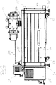
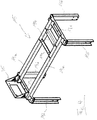
- the vacuum pumping station shown comprises a first vacuum pump 13, a second vacuum pump 17, a modular frame system consisting of a base frame 11 in the form of a housing for the first vacuum pump 13 and an additional frame 15 made up of several rod-shaped Profile elements 19 (see also Fig. 4 and 5 ) is assembled, and two control cabinets 25, 27 for the two vacuum pumps 13, 17.
- the first vacuum pump 13 is a dry screw pump that serves as a backing pump for the second pump 17, which is formed here by a Roots pump.
- the inlet 18 of the Roots pump 17 is located on its top side and is shown in FIG Fig. 1 , 2 and 3 closed by a cover.
- An object to be evacuated, for example a process chamber, which is not shown here, is connected to the inlet 18 of the Roots pump 17 during normal pumping operation.
- the overall arrangement of pumps on the one hand and the object to be evacuated on the other hand is referred to as a pumping station.
- the object to be evacuated does not belong to the pumping station.
- the components shown here belong to the pumping station.
- these components include the two pumps 13, 17, the base frame 11 of the screw pump 13, the additional frame 15 for the Roots pump 17 and the two switch cabinets 25, 27.
- the lower switch cabinet 25 is the lower vacuum pump, i.e. the screw pump 13 and thus the backing pump, while the upper switchgear cabinet 27 is assigned to the upper vacuum pump, namely the Roots pump 17.
- the Roots pump 17 is connected to its switchgear cabinet 27 by an electrical line 29.
- the screw pump 13 can also be connected to its switchgear cabinet 25 via one or more lines.
- the connection can be made by one or more electrical plug connections.
- the two switch cabinets 25, 27 form functional modules in the sense of the present disclosure.
- the entire pumping station according to Fig. 1 , 2 and 3 is supported on the base frame 11 on the floor or on any other lower part, not shown here, which carries the entire pumping station.
- the base frame 11 is provided with feet 31.
- the base frame 11 is also provided with castors 33.
- the castors 33 are passive.
- the feet 31 are transferred to a passive position or the castors 33 are transferred to an active driving position, or these two measures are carried out. All of these variants are basically possible.
- the screw pump 13 is supported by the already mentioned base frame 11, which is designed here as an essentially cuboid housing and comprises a plurality of panel-shaped sheet metal elements which surround the screw pump 13.
- the side walls of this housing 11 do not extend to the floor, as in particular the Fig. 2 can be found.
- the screw pump 13 is thus received within the housing 11, that is to say lies in the base frame formed by the housing 11.
- vibration decoupling can be provided between the screw pump 13 and the housing 11, for example in the form of appropriately designed feet (not shown) or buffers of the screw pump 13.
- the screw pump 13 can be used individually without serving as a backing pump for another pump. When the screw pump 13 is used as a single pump is in use, it is also provided with the base frame 11 forming the housing. This sheet metal housing 11 is inexpensive to manufacture and has a low weight. Mechanical oversizing is thus avoided for the individual operation of the screw pump 13.
- the additional frame 15 can be pushed onto the base frame 11 to form the pumping station.
- openings are formed, via which the additional frame 15 can be screwed to the base frame 11 in order to form a stable and torsion-resistant overall configuration.
- Such a screw connection or other fastening of the additional frame 15 on the base frame 11 by means of separate fastening elements is not mandatory.
- the two frames 11, 15 are simply put together in the intended manner by, for example - as in the exemplary embodiment of Fig. 1 , 2 and 3 - one frame is pushed over the other frame.
- the Roots pump 17 is supported on the additional frame 15, ie the Roots pump 17 is not directly supported by the base frame 11 or by the screw pump 13.
- the additional frame 15 is provided with two comparatively short profile elements 19b, which are arranged between two longitudinal profiles 19a extending in the longitudinal direction of the base frame 11.
- the Roots pump 17 rests on these transverse profiles 19b. This support of the Roots pump 17 on the additional frame 15 can be decoupled from vibrations.
- Roots pump 17 is vacuum-connected at its outlet formed on the underside with the inlet of the screw pump 13, in the embodiment shown here by a bellows 37
- the vacuum pumps used naturally depend on their specific design.
- the gas pumped out by the object to be evacuated leaves the pumping station via an outlet 14 of the screw pump 13.
- the additional frame 15 is also used to attach the aforementioned switch cabinets 25, 27.
- the additional frame 15 is provided at one end with a holder 35 which protrudes upward from that plane of the additional frame 15 which is defined by the two aforementioned longitudinal profiles 19a , between which the two transverse profiles 19b to support the Roots pump 17 extend.
- the switchgear cabinet 27 of the Roots pump 17 is fastened to this holder 35, for example by screwing.
- control cabinet 25 of the screw pump 13 is attached on the outside to one or more of those profile elements 19c, 19d which form one of the two frame parts provided in the form of a downwardly open "U" which each comprise an upper transverse profile 19c and two vertical profiles 19d extending vertically downward from this.
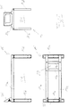
- FIG. 5 Such as in particular the long side view at the top left, the top view at the bottom left and the front view at the top right in Fig. 5 show, through the additional frame 15, a receiving space 21 for the first vacuum pump - here the screw pump 13 - including the base frame 11 below the plane defined by the longitudinal profiles 19a and the transverse profiles 19b and above this plane a support area 23 formed by these profiles 19a, 19b for the second vacuum pump 17 - here the Roots pump.
- the modular design of the frame system formed by the additional frame 15 and the base frame 11 makes it possible to create a pumping station of high mechanical stability and load-bearing capacity, in which the upper pump can be supported on the lower pump or on the base frame 11 of the lower pump without that in the case of single operation of the lower pump, it must be equipped with an oversized frame.
Landscapes
- Engineering & Computer Science (AREA)
- General Engineering & Computer Science (AREA)
- Mechanical Engineering (AREA)
- Compressors, Vaccum Pumps And Other Relevant Systems (AREA)
Claims (12)
- Système de cadre modulaire pour pompes à vide,comportant un cadre de base (11) pour une première pompe à vide (13), et un cadre supplémentaire séparé (15), prévu en supplément au cadre de base (11), pour une deuxième pompe à vide (17),
dans lequelle cadre de base (11) est réalisé aussi bien pour le fonctionnement en pompage de la première pompe à vide (13), sans le cadre supplémentaire (15) et sans la deuxième pompe à vide (17), que pour le fonctionnement en pompage commun des deux pompes à vide (13, 17), dans lequel les deux pompes à vide (13, 17) forment un poste de pompage et sont reliées l'une à l'autre en termes de vide, etle cadre de base (11) et le cadre supplémentaire (15) sont réalisés de telle sorte que, pour former le poste de pompage, le cadre supplémentaire (15) peut être supporté sur le cadre de base (11) et la deuxième pompe à vide (17) peut être supportée sur le cadre supplémentaire (15),caractérisé en ce queun module fonctionnel (25), en particulier une armoire de commande, associé(e) à la première pompe à vide (13), et un module fonctionnel (27), en particulier une armoire de commande, associé(e) à la deuxième pompe à vide (17), sont fixés au cadre supplémentaire (15) dans différentes positions verticales, en particulier verticalement l'un au-dessus de l'autre, et peuvent chacun être reliés à la pompe à vide (13, 17) associée, en particulier par une ou plusieurs lignes électriques (29) et/ou connexions à fiches. - Système à vide comportant au moins une première pompe à vide (13) et au moins une deuxième pompe à vide (17) et comportant au moins un système de cadre modulaire selon la revendication 1,
dans lequel le cadre de base (11) et le cadre supplémentaire (15) du système de cadre sont réalisés pour former, conjointement avec les pompes à vide (13, 17), un poste de pompage dans lequel les pompes à vide (13, 17) sont reliées l'une à l'autre en termes de vide et le cadre supplémentaire (15) est supporté sur le cadre de base (11) et la deuxième pompe à vide (17) est supportée sur le cadre supplémentaire (15). - Système à vide selon la revendication 2,
dans lequel les deux pompes à vide (13, 17) et le système de cadre sont assemblés pour former un poste de pompage. - Système selon l'une des revendications précédentes,
dans lequel, dans le poste de pompage, le cadre supplémentaire (15) est supporté exclusivement sur le cadre de base (11) et/ou la deuxième pompe à vide (17) est supportée exclusivement sur le cadre supplémentaire (15). - Système selon l'une des revendications précédentes,
dans lequel, dans le poste de pompage, le cadre de base (11) est supporté exclusivement directement au sol ou exclusivement sur la première pompe à vide (13) supportée au sol. - Système selon l'une des revendications précédentes,
dans lequel, dans le poste de pompage, la deuxième pompe à vide (17) est disposée verticalement au-dessus de la première pompe à vide (13). - Système selon l'une des revendications précédentes,
dans laquelle, dans le poste de pompage, le cadre de base (11) et le cadre supplémentaire (15) supporté sur le cadre de base (11) sont disposés l'un par rapport à l'autre de telle sorte que les deux cadres (11, 15) se chevauchent ou sont emboîtés l'un dans l'autre dans la direction verticale, en particulier, l'un des cadres (15, 11), de préférence le cadre supplémentaire (15), étant enfiché ou enfilé sur l'autre cadre (11, 15) ou étant enfiché, enfilé ou disposé en coiffe par-dessus l'autre cadre (11, 15). - Système selon l'une des revendications précédentes,
dans lequel le cadre de base est réalisé sous forme de boîtier (11) dans lequel est disposée la première pompe à vide (13), en particulier le boîtier (11) et la première pompe à vide (13) étant reliés l'un à l'autre et la liaison entre le boîtier (11) et la première pompe à vide (13) comprenant un découplage vis-à-vis des vibrations. - Système selon l'une des revendications précédentes,
dans lequel le cadre de base comprend un boîtier (11) pour la première pompe à vide (13), qui comprend plusieurs éléments en tôle en forme de panneau et qui est en particulier de forme parallélépipédique, et le cadre supplémentaire (15) comprend une pluralité d'éléments profilés en forme de tige (19) reliés les uns aux autres, qui sont fixés de manière détachable au boîtier (11), en particulier aux éléments en tôle du boîtier (11), dans le poste de pompage. - Système selon l'une des revendications précédentes,
dans lequel le cadre supplémentaire (15) comprend un espace de réception (21) pour la première pompe à vide (13) et une zone de support (23) pour la deuxième pompe à vide (17), et la zone de support (23) est située verticalement au-dessus de l'espace de réception (21). - Système selon l'une des revendications précédentes,
dans lequel la première pompe à vide (13) est une pompe à vis, en particulier une pompe à vis sèche, et/ou la deuxième pompe à vide (17) est une pompe Roots. - Système selon l'une des revendications précédentes,
dans lequel, dans le poste de pompage, la première pompe à vide (13) est une pompe préliminaire pour la deuxième pompe à vide (17).
Priority Applications (1)
| Application Number | Priority Date | Filing Date | Title |
|---|---|---|---|
| EP19199579.4A EP3623632B1 (fr) | 2019-09-25 | 2019-09-25 | Système de cadre modulaire pour pompes à vide |
Applications Claiming Priority (1)
| Application Number | Priority Date | Filing Date | Title |
|---|---|---|---|
| EP19199579.4A EP3623632B1 (fr) | 2019-09-25 | 2019-09-25 | Système de cadre modulaire pour pompes à vide |
Publications (3)
| Publication Number | Publication Date |
|---|---|
| EP3623632A2 EP3623632A2 (fr) | 2020-03-18 |
| EP3623632A3 EP3623632A3 (fr) | 2020-04-08 |
| EP3623632B1 true EP3623632B1 (fr) | 2021-09-15 |
Family
ID=68069557
Family Applications (1)
| Application Number | Title | Priority Date | Filing Date |
|---|---|---|---|
| EP19199579.4A Active EP3623632B1 (fr) | 2019-09-25 | 2019-09-25 | Système de cadre modulaire pour pompes à vide |
Country Status (1)
| Country | Link |
|---|---|
| EP (1) | EP3623632B1 (fr) |
Family Cites Families (4)
| Publication number | Priority date | Publication date | Assignee | Title |
|---|---|---|---|---|
| JPH05113180A (ja) * | 1991-09-05 | 1993-05-07 | Ebara Corp | 真空ポンプの連結装置 |
| KR100809852B1 (ko) * | 2007-05-17 | 2008-03-04 | (주)엘오티베큠 | 일체형 진공발생장치 |
| DE202015005199U1 (de) * | 2015-07-18 | 2015-08-18 | Vacuubrand Gmbh + Co Kg | Vakuumpumpstand mit mindestens zwei Membranpumpen |
| DE102017120655A1 (de) * | 2017-09-07 | 2019-03-07 | Khs Corpoplast Gmbh | Tragrahmen für einen Pumpenstand zur Aufnahme von Vakuumpumpen und Haupttragrahmen für eine Beschichtungsvorrichtung von Behältern und Beschichtungsvorrichtung |
-
2019
- 2019-09-25 EP EP19199579.4A patent/EP3623632B1/fr active Active
Also Published As
| Publication number | Publication date |
|---|---|
| EP3623632A2 (fr) | 2020-03-18 |
| EP3623632A3 (fr) | 2020-04-08 |
Similar Documents
| Publication | Publication Date | Title |
|---|---|---|
| DE102007012079B4 (de) | Verteilerschrank mit mehreren Innengehäusen | |
| DE102014107168B4 (de) | Rahmengestell für Elektronik- oder Netzwerkschränke | |
| DE69402525T2 (de) | Gerüst mit variabler grösse für elektrische und/oder elektronische anlage | |
| DE202014100664U1 (de) | Kühlregal | |
| EP3282894A1 (fr) | Support de table pour table | |
| EP3104749B1 (fr) | Vitrine réfrigérante | |
| EP0830825B1 (fr) | Elément de liaison pour cadre de meuble, ensemble d'assemblage pour support de meuble et jeu de construction pour l'assemblage d'un meuble | |
| DE10147361A1 (de) | Verpackungsmaschine mit Roboterhimmel | |
| DE102006003349A1 (de) | Geräteschrank mit einem aus Profilen hergestellten, quaderförmigen Schrankgerüst, aufweisend geschraubte Eckverbinder | |
| EP4064937A1 (fr) | Meuble en kit | |
| DE102015226598B4 (de) | Verfahren zum Aufbau einer Möbelanordnung und zugehörige Möbelanordnung | |
| DE69705260T2 (de) | Modularer metallischer Schrank für elektrisches Gerät, für eine Wand- oder Bodenbefestigung | |
| EP4064940A1 (fr) | Traverse, ensemble traverse et kit de meubles | |
| EP3623632B1 (fr) | Système de cadre modulaire pour pompes à vide | |
| DE202014100665U1 (de) | Kühlregal | |
| EP3084902B1 (fr) | Châssis pour amoire électrique avec plaque de fond démontable pour barres de distribution ainsi qu'une méthode d'assemblage d'une telle armoire | |
| DE202008012023U1 (de) | Tischkonstruktion | |
| EP3607624B1 (fr) | Ensemble comprenant un socle et un châssis pour armoire électrique ainsi qu'une rangée d'armoires électriques | |
| WO2000054929A2 (fr) | Machine-outil | |
| EP3456220B1 (fr) | Système de poste de travail avec zone de montage flexible | |
| DE29909433U1 (de) | Schaltgeräteschrank | |
| EP4114150A1 (fr) | Ensemble d'extension | |
| EP3276099B1 (fr) | Conteneur de transport | |
| EP2712516A2 (fr) | Système de levage pour un système de poste de travail réglable en hauteur et système de poste de travail doté d'un tel système de levage | |
| DE1598805A1 (de) | Laboreinrichtung mit in Reihe aufgestellten Einzelzellen |
Legal Events
| Date | Code | Title | Description |
|---|---|---|---|
| PUAI | Public reference made under article 153(3) epc to a published international application that has entered the european phase |
Free format text: ORIGINAL CODE: 0009012 |
|
| STAA | Information on the status of an ep patent application or granted ep patent |
Free format text: STATUS: THE APPLICATION HAS BEEN PUBLISHED |
|
| PUAL | Search report despatched |
Free format text: ORIGINAL CODE: 0009013 |
|
| AK | Designated contracting states |
Kind code of ref document: A2 Designated state(s): AL AT BE BG CH CY CZ DE DK EE ES FI FR GB GR HR HU IE IS IT LI LT LU LV MC MK MT NL NO PL PT RO RS SE SI SK SM TR |
|
| AK | Designated contracting states |
Kind code of ref document: A3 Designated state(s): AL AT BE BG CH CY CZ DE DK EE ES FI FR GB GR HR HU IE IS IT LI LT LU LV MC MK MT NL NO PL PT RO RS SE SI SK SM TR |
|
| RIC1 | Information provided on ipc code assigned before grant |
Ipc: F04D 17/16 20060101ALI20200304BHEP Ipc: F04D 29/60 20060101ALI20200304BHEP Ipc: F04D 19/04 20060101ALI20200304BHEP Ipc: F16M 1/04 20060101ALI20200304BHEP Ipc: F04C 29/00 20060101AFI20200304BHEP |
|
| STAA | Information on the status of an ep patent application or granted ep patent |
Free format text: STATUS: REQUEST FOR EXAMINATION WAS MADE |
|
| 17P | Request for examination filed |
Effective date: 20200630 |
|
| RBV | Designated contracting states (corrected) |
Designated state(s): AL AT BE BG CH CY CZ DE DK EE ES FI FR GB GR HR HU IE IS IT LI LT LU LV MC MK MT NL NO PL PT RO RS SE SI SK SM TR |
|
| GRAP | Despatch of communication of intention to grant a patent |
Free format text: ORIGINAL CODE: EPIDOSNIGR1 |
|
| STAA | Information on the status of an ep patent application or granted ep patent |
Free format text: STATUS: GRANT OF PATENT IS INTENDED |
|
| INTG | Intention to grant announced |
Effective date: 20210416 |
|
| GRAS | Grant fee paid |
Free format text: ORIGINAL CODE: EPIDOSNIGR3 |
|
| GRAA | (expected) grant |
Free format text: ORIGINAL CODE: 0009210 |
|
| STAA | Information on the status of an ep patent application or granted ep patent |
Free format text: STATUS: THE PATENT HAS BEEN GRANTED |
|
| AK | Designated contracting states |
Kind code of ref document: B1 Designated state(s): AL AT BE BG CH CY CZ DE DK EE ES FI FR GB GR HR HU IE IS IT LI LT LU LV MC MK MT NL NO PL PT RO RS SE SI SK SM TR |
|
| REG | Reference to a national code |
Ref country code: CH Ref legal event code: EP |
|
| REG | Reference to a national code |
Ref country code: DE Ref legal event code: R096 Ref document number: 502019002287 Country of ref document: DE |
|
| REG | Reference to a national code |
Ref country code: IE Ref legal event code: FG4D Free format text: LANGUAGE OF EP DOCUMENT: GERMAN |
|
| REG | Reference to a national code |
Ref country code: AT Ref legal event code: REF Ref document number: 1430714 Country of ref document: AT Kind code of ref document: T Effective date: 20211015 |
|
| REG | Reference to a national code |
Ref country code: LT Ref legal event code: MG9D |
|
| REG | Reference to a national code |
Ref country code: NL Ref legal event code: MP Effective date: 20210915 |
|
| PG25 | Lapsed in a contracting state [announced via postgrant information from national office to epo] |
Ref country code: FI Free format text: LAPSE BECAUSE OF FAILURE TO SUBMIT A TRANSLATION OF THE DESCRIPTION OR TO PAY THE FEE WITHIN THE PRESCRIBED TIME-LIMIT Effective date: 20210915 Ref country code: RS Free format text: LAPSE BECAUSE OF FAILURE TO SUBMIT A TRANSLATION OF THE DESCRIPTION OR TO PAY THE FEE WITHIN THE PRESCRIBED TIME-LIMIT Effective date: 20210915 Ref country code: SE Free format text: LAPSE BECAUSE OF FAILURE TO SUBMIT A TRANSLATION OF THE DESCRIPTION OR TO PAY THE FEE WITHIN THE PRESCRIBED TIME-LIMIT Effective date: 20210915 Ref country code: LT Free format text: LAPSE BECAUSE OF FAILURE TO SUBMIT A TRANSLATION OF THE DESCRIPTION OR TO PAY THE FEE WITHIN THE PRESCRIBED TIME-LIMIT Effective date: 20210915 Ref country code: BG Free format text: LAPSE BECAUSE OF FAILURE TO SUBMIT A TRANSLATION OF THE DESCRIPTION OR TO PAY THE FEE WITHIN THE PRESCRIBED TIME-LIMIT Effective date: 20211215 Ref country code: HR Free format text: LAPSE BECAUSE OF FAILURE TO SUBMIT A TRANSLATION OF THE DESCRIPTION OR TO PAY THE FEE WITHIN THE PRESCRIBED TIME-LIMIT Effective date: 20210915 Ref country code: NO Free format text: LAPSE BECAUSE OF FAILURE TO SUBMIT A TRANSLATION OF THE DESCRIPTION OR TO PAY THE FEE WITHIN THE PRESCRIBED TIME-LIMIT Effective date: 20211215 |
|
| PG25 | Lapsed in a contracting state [announced via postgrant information from national office to epo] |
Ref country code: LV Free format text: LAPSE BECAUSE OF FAILURE TO SUBMIT A TRANSLATION OF THE DESCRIPTION OR TO PAY THE FEE WITHIN THE PRESCRIBED TIME-LIMIT Effective date: 20210915 Ref country code: GR Free format text: LAPSE BECAUSE OF FAILURE TO SUBMIT A TRANSLATION OF THE DESCRIPTION OR TO PAY THE FEE WITHIN THE PRESCRIBED TIME-LIMIT Effective date: 20211216 |
|
| REG | Reference to a national code |
Ref country code: BE Ref legal event code: MM Effective date: 20210930 |
|
| PG25 | Lapsed in a contracting state [announced via postgrant information from national office to epo] |
Ref country code: IS Free format text: LAPSE BECAUSE OF FAILURE TO SUBMIT A TRANSLATION OF THE DESCRIPTION OR TO PAY THE FEE WITHIN THE PRESCRIBED TIME-LIMIT Effective date: 20220115 Ref country code: SM Free format text: LAPSE BECAUSE OF FAILURE TO SUBMIT A TRANSLATION OF THE DESCRIPTION OR TO PAY THE FEE WITHIN THE PRESCRIBED TIME-LIMIT Effective date: 20210915 Ref country code: SK Free format text: LAPSE BECAUSE OF FAILURE TO SUBMIT A TRANSLATION OF THE DESCRIPTION OR TO PAY THE FEE WITHIN THE PRESCRIBED TIME-LIMIT Effective date: 20210915 Ref country code: RO Free format text: LAPSE BECAUSE OF FAILURE TO SUBMIT A TRANSLATION OF THE DESCRIPTION OR TO PAY THE FEE WITHIN THE PRESCRIBED TIME-LIMIT Effective date: 20210915 Ref country code: PT Free format text: LAPSE BECAUSE OF FAILURE TO SUBMIT A TRANSLATION OF THE DESCRIPTION OR TO PAY THE FEE WITHIN THE PRESCRIBED TIME-LIMIT Effective date: 20220117 Ref country code: PL Free format text: LAPSE BECAUSE OF FAILURE TO SUBMIT A TRANSLATION OF THE DESCRIPTION OR TO PAY THE FEE WITHIN THE PRESCRIBED TIME-LIMIT Effective date: 20210915 Ref country code: NL Free format text: LAPSE BECAUSE OF FAILURE TO SUBMIT A TRANSLATION OF THE DESCRIPTION OR TO PAY THE FEE WITHIN THE PRESCRIBED TIME-LIMIT Effective date: 20210915 Ref country code: ES Free format text: LAPSE BECAUSE OF FAILURE TO SUBMIT A TRANSLATION OF THE DESCRIPTION OR TO PAY THE FEE WITHIN THE PRESCRIBED TIME-LIMIT Effective date: 20210915 Ref country code: EE Free format text: LAPSE BECAUSE OF FAILURE TO SUBMIT A TRANSLATION OF THE DESCRIPTION OR TO PAY THE FEE WITHIN THE PRESCRIBED TIME-LIMIT Effective date: 20210915 Ref country code: AL Free format text: LAPSE BECAUSE OF FAILURE TO SUBMIT A TRANSLATION OF THE DESCRIPTION OR TO PAY THE FEE WITHIN THE PRESCRIBED TIME-LIMIT Effective date: 20210915 |
|
| REG | Reference to a national code |
Ref country code: DE Ref legal event code: R097 Ref document number: 502019002287 Country of ref document: DE |
|
| PG25 | Lapsed in a contracting state [announced via postgrant information from national office to epo] |
Ref country code: MC Free format text: LAPSE BECAUSE OF FAILURE TO SUBMIT A TRANSLATION OF THE DESCRIPTION OR TO PAY THE FEE WITHIN THE PRESCRIBED TIME-LIMIT Effective date: 20210915 |
|
| PLBE | No opposition filed within time limit |
Free format text: ORIGINAL CODE: 0009261 |
|
| STAA | Information on the status of an ep patent application or granted ep patent |
Free format text: STATUS: NO OPPOSITION FILED WITHIN TIME LIMIT |
|
| PG25 | Lapsed in a contracting state [announced via postgrant information from national office to epo] |
Ref country code: LU Free format text: LAPSE BECAUSE OF NON-PAYMENT OF DUE FEES Effective date: 20210925 Ref country code: IE Free format text: LAPSE BECAUSE OF NON-PAYMENT OF DUE FEES Effective date: 20210925 Ref country code: DK Free format text: LAPSE BECAUSE OF FAILURE TO SUBMIT A TRANSLATION OF THE DESCRIPTION OR TO PAY THE FEE WITHIN THE PRESCRIBED TIME-LIMIT Effective date: 20210915 Ref country code: BE Free format text: LAPSE BECAUSE OF NON-PAYMENT OF DUE FEES Effective date: 20210930 |
|
| 26N | No opposition filed |
Effective date: 20220616 |
|
| PG25 | Lapsed in a contracting state [announced via postgrant information from national office to epo] |
Ref country code: SI Free format text: LAPSE BECAUSE OF FAILURE TO SUBMIT A TRANSLATION OF THE DESCRIPTION OR TO PAY THE FEE WITHIN THE PRESCRIBED TIME-LIMIT Effective date: 20210915 |
|
| PG25 | Lapsed in a contracting state [announced via postgrant information from national office to epo] |
Ref country code: FR Free format text: LAPSE BECAUSE OF NON-PAYMENT OF DUE FEES Effective date: 20211115 |
|
| REG | Reference to a national code |
Ref country code: CH Ref legal event code: PL |
|
| PG25 | Lapsed in a contracting state [announced via postgrant information from national office to epo] |
Ref country code: CY Free format text: LAPSE BECAUSE OF FAILURE TO SUBMIT A TRANSLATION OF THE DESCRIPTION OR TO PAY THE FEE WITHIN THE PRESCRIBED TIME-LIMIT Effective date: 20210915 |
|
| PG25 | Lapsed in a contracting state [announced via postgrant information from national office to epo] |
Ref country code: LI Free format text: LAPSE BECAUSE OF NON-PAYMENT OF DUE FEES Effective date: 20220930 Ref country code: HU Free format text: LAPSE BECAUSE OF FAILURE TO SUBMIT A TRANSLATION OF THE DESCRIPTION OR TO PAY THE FEE WITHIN THE PRESCRIBED TIME-LIMIT; INVALID AB INITIO Effective date: 20190925 Ref country code: CH Free format text: LAPSE BECAUSE OF NON-PAYMENT OF DUE FEES Effective date: 20220930 |
|
| PG25 | Lapsed in a contracting state [announced via postgrant information from national office to epo] |
Ref country code: MK Free format text: LAPSE BECAUSE OF FAILURE TO SUBMIT A TRANSLATION OF THE DESCRIPTION OR TO PAY THE FEE WITHIN THE PRESCRIBED TIME-LIMIT Effective date: 20210915 |
|
| PG25 | Lapsed in a contracting state [announced via postgrant information from national office to epo] |
Ref country code: TR Free format text: LAPSE BECAUSE OF FAILURE TO SUBMIT A TRANSLATION OF THE DESCRIPTION OR TO PAY THE FEE WITHIN THE PRESCRIBED TIME-LIMIT Effective date: 20210915 |
|
| PG25 | Lapsed in a contracting state [announced via postgrant information from national office to epo] |
Ref country code: MT Free format text: LAPSE BECAUSE OF FAILURE TO SUBMIT A TRANSLATION OF THE DESCRIPTION OR TO PAY THE FEE WITHIN THE PRESCRIBED TIME-LIMIT Effective date: 20210915 |
|
| PGFP | Annual fee paid to national office [announced via postgrant information from national office to epo] |
Ref country code: IT Payment date: 20250923 Year of fee payment: 7 |
|
| PGFP | Annual fee paid to national office [announced via postgrant information from national office to epo] |
Ref country code: GB Payment date: 20250919 Year of fee payment: 7 |
|
| PGFP | Annual fee paid to national office [announced via postgrant information from national office to epo] |
Ref country code: CZ Payment date: 20250916 Year of fee payment: 7 |
|
| REG | Reference to a national code |
Ref country code: AT Ref legal event code: MM01 Ref document number: 1430714 Country of ref document: AT Kind code of ref document: T Effective date: 20240925 |
|
| PGFP | Annual fee paid to national office [announced via postgrant information from national office to epo] |
Ref country code: DE Payment date: 20251126 Year of fee payment: 7 |
|
| PG25 | Lapsed in a contracting state [announced via postgrant information from national office to epo] |
Ref country code: AT Free format text: LAPSE BECAUSE OF NON-PAYMENT OF DUE FEES Effective date: 20240925 |
|
| PGFP | Annual fee paid to national office [announced via postgrant information from national office to epo] |
Ref country code: AT Payment date: 20260410 Year of fee payment: 5 |