EP3623632B1 - Modulares rahmensystem für vakuumpumpen - Google Patents
Modulares rahmensystem für vakuumpumpen Download PDFInfo
- Publication number
- EP3623632B1 EP3623632B1 EP19199579.4A EP19199579A EP3623632B1 EP 3623632 B1 EP3623632 B1 EP 3623632B1 EP 19199579 A EP19199579 A EP 19199579A EP 3623632 B1 EP3623632 B1 EP 3623632B1
- Authority
- EP
- European Patent Office
- Prior art keywords
- frame
- vacuum pump
- vacuum
- pump
- base frame
- Prior art date
- Legal status (The legal status is an assumption and is not a legal conclusion. Google has not performed a legal analysis and makes no representation as to the accuracy of the status listed.)
- Active
Links
Images


Classifications
-
- F—MECHANICAL ENGINEERING; LIGHTING; HEATING; WEAPONS; BLASTING
- F04—POSITIVE - DISPLACEMENT MACHINES FOR LIQUIDS; PUMPS FOR LIQUIDS OR ELASTIC FLUIDS
- F04D—NON-POSITIVE-DISPLACEMENT PUMPS
- F04D29/00—Details, component parts, or accessories
- F04D29/60—Mounting; Assembling; Disassembling
- F04D29/601—Mounting; Assembling; Disassembling specially adapted for elastic fluid pumps
-
- F—MECHANICAL ENGINEERING; LIGHTING; HEATING; WEAPONS; BLASTING
- F04—POSITIVE - DISPLACEMENT MACHINES FOR LIQUIDS; PUMPS FOR LIQUIDS OR ELASTIC FLUIDS
- F04C—ROTARY-PISTON, OR OSCILLATING-PISTON, POSITIVE-DISPLACEMENT MACHINES FOR LIQUIDS; ROTARY-PISTON, OR OSCILLATING-PISTON, POSITIVE-DISPLACEMENT PUMPS
- F04C29/00—Component parts, details or accessories of pumps or pumping installations, not provided for in groups F04C18/00 - F04C28/00
-
- F—MECHANICAL ENGINEERING; LIGHTING; HEATING; WEAPONS; BLASTING
- F04—POSITIVE - DISPLACEMENT MACHINES FOR LIQUIDS; PUMPS FOR LIQUIDS OR ELASTIC FLUIDS
- F04D—NON-POSITIVE-DISPLACEMENT PUMPS
- F04D19/00—Axial-flow pumps
- F04D19/02—Multi-stage pumps
- F04D19/04—Multi-stage pumps specially adapted to the production of a high vacuum, e.g. molecular pumps
-
- F—MECHANICAL ENGINEERING; LIGHTING; HEATING; WEAPONS; BLASTING
- F04—POSITIVE - DISPLACEMENT MACHINES FOR LIQUIDS; PUMPS FOR LIQUIDS OR ELASTIC FLUIDS
- F04D—NON-POSITIVE-DISPLACEMENT PUMPS
- F04D25/00—Pumping installations or systems
- F04D25/16—Combinations of two or more pumps ; Producing two or more separate gas flows
-
- F—MECHANICAL ENGINEERING; LIGHTING; HEATING; WEAPONS; BLASTING
- F16—ENGINEERING ELEMENTS AND UNITS; GENERAL MEASURES FOR PRODUCING AND MAINTAINING EFFECTIVE FUNCTIONING OF MACHINES OR INSTALLATIONS; THERMAL INSULATION IN GENERAL
- F16M—FRAMES, CASINGS OR BEDS OF ENGINES, MACHINES OR APPARATUS, NOT SPECIFIC TO ENGINES, MACHINES OR APPARATUS PROVIDED FOR ELSEWHERE; STANDS; SUPPORTS
- F16M1/00—Frames or casings of engines, machines or apparatus; Frames serving as machinery beds
- F16M1/04—Frames or casings of engines, machines or apparatus; Frames serving as machinery beds for rotary engines or similar machines
Definitions
- the invention relates to a modular frame system for vacuum pumps and a vacuum system with at least two vacuum pumps and at least one modular frame system according to the invention.
- vacuum pumps are used either individually or together with one or more other vacuum pumps.
- a combination of several vacuum pumps is also known as a pumping station.
- the vacuum pumps are usually arranged one above the other, so that measures are required to be able to bear the weight of the upper pump or the upper pumps.
- Vacuum pumps often have an outer frame that accommodates the individual functional elements of the pump. Not all functional parts have to be arranged within the frame. Some function modules, for example switch cabinets containing electrical control, regulation and supply components, can also be located outside the frame and thereby be supported by the frame.
- the frames of individual pumps are often essentially closed housings made of sheet metal elements. Such housings are inexpensive, have a low weight and can easily meet the requirements of a single pump.
- massive frames are usually used, which are not closed housings, but rather several stable rod-shaped support elements to form a type of support or lattice structure are composed, which stands on the floor and on which the vacuum pumps forming the pumping station are supported.
- Such massive support frames are necessary because the aforementioned lightweight sheet metal housings of individual pumps could not bear the weight of an additional pump.
- a frame system with the features of the preamble of claim 1 is from DE 20 2015 005 199 U1 and JPH 05 113 180 known.
- the object of the invention is therefore to create a simple and inexpensive option for operating vacuum pumps which, in particular with regard to mechanical stability, meets the requirements of vacuum pumps both in operation as a single pump and in a pumping station comprising several vacuum pumps.
- this object is achieved by a modular frame system for vacuum pumps with a base frame for a first vacuum pump, and with a separate additional frame for a second vacuum pump provided in addition to the base frame, the base frame for both pumping operation of the first vacuum pump is designed without the additional frame and without the second vacuum pump as well as for a common pumping operation of both vacuum pumps, in which the two vacuum pumps form a pumping station and are vacuum-connected to each other, and wherein the base frame and the additional frame are designed such that the Additional frame can be supported on the base frame and the second vacuum pump can be supported on the additional frame, one functional module assigned to the first vacuum pump and one to the second Function module assigned to the vacuum pump is attached to the additional frame in different vertical positions and each connected to the assigned vacuum pump.
- At least one of the function modules is a switch cabinet with electrical and / or electronic components for controlling, regulating and / or supplying the respective vacuum pump.
- the fastening options which the additional frame forms for the function modules are preferably provided in such a way that the function modules can be fastened vertically one above the other on the additional frame.
- connection between the vacuum pump and the assigned function module can be made by one or more electrical lines and / or by plug connections.
- the object is achieved by a vacuum system with at least one first vacuum pump and at least one second vacuum pump and with at least one modular frame system as disclosed herein, wherein the base frame and the additional frame of the frame system are designed to work together with the vacuum pumps to form a pumping station in which the vacuum pumps are connected to one another in terms of vacuum technology and the additional frame is supported on the base frame and the second vacuum pump is supported on the additional frame.
- the invention also relates to a vacuum system of the type mentioned above, in which the two vacuum pumps and the frame system are combined to form a pumping unit, ie the invention relates not only to the individual components of the vacuum system mentioned above, but also to an operational pumping unit in which the individual units mentioned Components are put together as intended to form a pumping station.
- a vacuum connection between two or more vacuum pumps is to be understood as a connection such that the pumps work together to produce a respective pumping action.
- the pumps can be connected in series or in parallel.
- the number of pumps connected to one another in terms of vacuum technology is basically arbitrary.
- the pumps can, for example, be connected to one another in the manner of a cascade.
- a vacuum connection between two vacuum pumps can be used, for example, so that one vacuum pump forms a backing pump for the other vacuum pump.
- the modular frame system enables flexible adaptation to the respective stability requirements. If, in a specific application, a vacuum pump is to be operated individually, i.e. not operated as part of a pumping station, then it is sufficient to provide the pump with the base frame. Depending on the pump type, a vacuum pump can already be provided with the base frame during manufacture, with which the pump then remains permanently connected. Alternatively, a pump can be provided with the base frame if required and only for the actual pumping operation. The base frame can meet all the requirements of this single pump and represents a cost-effective, relatively low-weight equipment for a vacuum pump.
- the modular frame system according to the invention makes it possible to use a vacuum pump provided with the base frame together with one or more further vacuum pumps in a pumping station.
- the additional frame according to the invention is used in this pumping station configuration.
- the base frame and the additional frame are matched to one another in such a way that the additional frame can be supported on the base frame.
- the mechanical stability and load-bearing capacity of the base frame are increased by the additional frame. This can reduce the weight of at least one further vacuum pump be worn.
- This further vacuum pump - here also referred to as the second vacuum pump - is supported on the additional frame.
- the additional vacuum pump does not have to be fully supported directly on the additional frame.
- Part of the weight of the further vacuum pump can be absorbed directly by the base frame and / or in front of the vacuum pump provided with the base frame, i.e. the further vacuum pump can also be partially supported on the vacuum pump provided with the base frame.
- Such a direct support of the two pumps with one another can take place, for example, by means of a mechanical connection which is used to connect the two vacuum pumps in terms of vacuum technology.
- a vacuum connection of the two vacuum pumps can, however, also take place in such a way that, although there is a mechanical connection between the two vacuum pumps, this does not contribute significantly to the support of one vacuum pump on the other vacuum pump. In such a case, a mechanical connection for the vacuum connection of the two vacuum pumps is not to be understood as a mechanical support within the meaning of the invention.
- the modular frame system according to the invention thus makes it possible to provide mechanical stability and load-bearing capacity in the form of the additional frame only when this is also necessary. Oversizing a single pump with regard to mechanical stability and load-bearing capacity is consequently avoided.
- the modular frame system according to the invention is not limited to a single base frame and a single additional frame.
- Several additional frames can be provided, with the additional frames being able to be coordinated with one another in such a way that an additional frame can be supported on one or more additional frames.
- the additional frames can be attached to different Be adapted to vacuum pumps.
- a plurality of vacuum pumps and a plurality of frames forming the components of the frame system according to the invention can be combined in any way to form a pumping station. Not all additional frames of the frame system have to be used at the same time.
- the respective operator can use the modular frame system according to the invention flexibly and select the appropriate additional frame or frames.
- several base frames can also be used at the same time if the pumping station comprises several such vacuum pumps, each of which is equipped with a base frame.
- the additional frame can be supported exclusively on the base frame.
- the additional frame is not supported on the ground either.
- the second vacuum pump in the pumping station can be supported exclusively on the additional frame.
- this does not exclude a mechanical connection between the two vacuum pumps, which is used in particular for the vacuum connection between the pumps, but can alternatively or additionally also serve other purposes, if this mechanical connection does not significantly support the one Vacuum pump contributes to the other vacuum pump.
- the base frame in the pumping station the base frame is supported exclusively directly on the floor or exclusively on the first vacuum pump which is supported on the floor. It can therefore be provided that the support on the floor is exclusively via the base frame takes place and the first vacuum pump is carried exclusively by the base frame.
- the base frame can be provided with feet, with the base frame being able to be provided with castors as an alternative or in addition.
- the base frame can be matched to the first vacuum pump in such a way that it is supported on the floor itself and the base frame is consequently supported exclusively on the first vacuum pump supported on the floor.
- a vibration decoupling is preferably provided between the first vacuum pump and the base frame.
- the first vacuum pump can be supported on the base frame with feet, each designed as a vibration damper or buffer element or provided with such dampers or elements, and, for example, can stand on the stand areas or stand sections provided for this purpose, which are formed on the base frame.
- the invention can also provide that the base frame and the first vacuum pump are matched to one another in such a way that the support on the floor is provided both by the first vacuum pump itself and by the base frame.
- the second vacuum pump is arranged vertically above the first vacuum pump in the pumping station.
- Such a vertical arrangement of the two vacuum pumps one above the other is not to be understood as meaning that the two vacuum pumps are merely located at different height levels, but are arranged next to one another.
- the base frame and the additional frame supported on the base frame are arranged relative to one another in the pumping station in such a way that the two frames overlap one another in the vertical direction or are nested in one another.
- one frame preferably the additional frame
- the additional frame can form, for example, an inner or outer stability structure for the base frame, so that its stability and load-bearing capacity are increased by the additional frame.
- One frame can be located entirely within the other frame. However, this is not mandatory, because only a partial overlap or nesting of the two frames can be provided.
- the base frame can be designed as a housing in which the first vacuum pump is arranged.
- the housing and the first vacuum pump can be connected to one another, the connection between the housing and the first vacuum pump comprising a vibration decoupling.
- the housing can only be supported on the floor and the first vacuum pump can only be supported on this housing, that is, not directly on the floor.
- the base frame comprises a plurality of sheet-metal elements in the form of a sheet, in particular a cuboid, housing for the first vacuum pump, the additional frame having a plurality of interconnected includes connected rod-shaped profile elements which are releasably attached in the pumping station to the housing, in particular to the sheet metal elements of the housing.
- the additional frame can only be attached to the housing. However, this is not mandatory. It is also possible that the additional frame can be fastened to the first vacuum pump, for example by means of fastening screws which extend through the housing into threaded receptacles which are formed on the first vacuum pump.
- the additional frame has a receiving space for the first vacuum pump and a support area for the second vacuum pump, the support area being located vertically above the receiving space.
- the first vacuum pump for which the base frame is provided, is, for example, a screw pump, in particular a dry screw pump.
- the second vacuum pump which is supported on the additional frame in the pumping station, is in particular a Roots pump.
- the first vacuum pump in the pumping station is a backing pump for the second vacuum pump.
- the pumping station comprises a screw pump as the first vacuum pump, which functions as a backing pump for a Roots pump forming the second vacuum pump, the Roots pump being arranged vertically above the screw pump and supported on the additional frame, which is supported on the base frame of the screw pump.
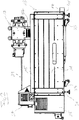
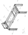
- the vacuum pumping station shown comprises a first vacuum pump 13, a second vacuum pump 17, a modular frame system consisting of a base frame 11 in the form of a housing for the first vacuum pump 13 and an additional frame 15 made up of several rod-shaped Profile elements 19 (see also Fig. 4 and 5 ) is assembled, and two control cabinets 25, 27 for the two vacuum pumps 13, 17.
- the first vacuum pump 13 is a dry screw pump that serves as a backing pump for the second pump 17, which is formed here by a Roots pump.
- the inlet 18 of the Roots pump 17 is located on its top side and is shown in FIG Fig. 1 , 2 and 3 closed by a cover.
- An object to be evacuated, for example a process chamber, which is not shown here, is connected to the inlet 18 of the Roots pump 17 during normal pumping operation.
- the overall arrangement of pumps on the one hand and the object to be evacuated on the other hand is referred to as a pumping station.
- the object to be evacuated does not belong to the pumping station.
- the components shown here belong to the pumping station.
- these components include the two pumps 13, 17, the base frame 11 of the screw pump 13, the additional frame 15 for the Roots pump 17 and the two switch cabinets 25, 27.
- the lower switch cabinet 25 is the lower vacuum pump, i.e. the screw pump 13 and thus the backing pump, while the upper switchgear cabinet 27 is assigned to the upper vacuum pump, namely the Roots pump 17.
- the Roots pump 17 is connected to its switchgear cabinet 27 by an electrical line 29.
- the screw pump 13 can also be connected to its switchgear cabinet 25 via one or more lines.
- the connection can be made by one or more electrical plug connections.
- the two switch cabinets 25, 27 form functional modules in the sense of the present disclosure.
- the entire pumping station according to Fig. 1 , 2 and 3 is supported on the base frame 11 on the floor or on any other lower part, not shown here, which carries the entire pumping station.
- the base frame 11 is provided with feet 31.
- the base frame 11 is also provided with castors 33.
- the castors 33 are passive.
- the feet 31 are transferred to a passive position or the castors 33 are transferred to an active driving position, or these two measures are carried out. All of these variants are basically possible.
- the screw pump 13 is supported by the already mentioned base frame 11, which is designed here as an essentially cuboid housing and comprises a plurality of panel-shaped sheet metal elements which surround the screw pump 13.
- the side walls of this housing 11 do not extend to the floor, as in particular the Fig. 2 can be found.
- the screw pump 13 is thus received within the housing 11, that is to say lies in the base frame formed by the housing 11.
- vibration decoupling can be provided between the screw pump 13 and the housing 11, for example in the form of appropriately designed feet (not shown) or buffers of the screw pump 13.
- the screw pump 13 can be used individually without serving as a backing pump for another pump. When the screw pump 13 is used as a single pump is in use, it is also provided with the base frame 11 forming the housing. This sheet metal housing 11 is inexpensive to manufacture and has a low weight. Mechanical oversizing is thus avoided for the individual operation of the screw pump 13.
- the additional frame 15 can be pushed onto the base frame 11 to form the pumping station.
- openings are formed, via which the additional frame 15 can be screwed to the base frame 11 in order to form a stable and torsion-resistant overall configuration.
- Such a screw connection or other fastening of the additional frame 15 on the base frame 11 by means of separate fastening elements is not mandatory.
- the two frames 11, 15 are simply put together in the intended manner by, for example - as in the exemplary embodiment of Fig. 1 , 2 and 3 - one frame is pushed over the other frame.
- the Roots pump 17 is supported on the additional frame 15, ie the Roots pump 17 is not directly supported by the base frame 11 or by the screw pump 13.
- the additional frame 15 is provided with two comparatively short profile elements 19b, which are arranged between two longitudinal profiles 19a extending in the longitudinal direction of the base frame 11.
- the Roots pump 17 rests on these transverse profiles 19b. This support of the Roots pump 17 on the additional frame 15 can be decoupled from vibrations.
- Roots pump 17 is vacuum-connected at its outlet formed on the underside with the inlet of the screw pump 13, in the embodiment shown here by a bellows 37
- the vacuum pumps used naturally depend on their specific design.
- the gas pumped out by the object to be evacuated leaves the pumping station via an outlet 14 of the screw pump 13.
- the additional frame 15 is also used to attach the aforementioned switch cabinets 25, 27.
- the additional frame 15 is provided at one end with a holder 35 which protrudes upward from that plane of the additional frame 15 which is defined by the two aforementioned longitudinal profiles 19a , between which the two transverse profiles 19b to support the Roots pump 17 extend.
- the switchgear cabinet 27 of the Roots pump 17 is fastened to this holder 35, for example by screwing.
- control cabinet 25 of the screw pump 13 is attached on the outside to one or more of those profile elements 19c, 19d which form one of the two frame parts provided in the form of a downwardly open "U" which each comprise an upper transverse profile 19c and two vertical profiles 19d extending vertically downward from this.
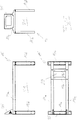
- FIG. 5 Such as in particular the long side view at the top left, the top view at the bottom left and the front view at the top right in Fig. 5 show, through the additional frame 15, a receiving space 21 for the first vacuum pump - here the screw pump 13 - including the base frame 11 below the plane defined by the longitudinal profiles 19a and the transverse profiles 19b and above this plane a support area 23 formed by these profiles 19a, 19b for the second vacuum pump 17 - here the Roots pump.
- the modular design of the frame system formed by the additional frame 15 and the base frame 11 makes it possible to create a pumping station of high mechanical stability and load-bearing capacity, in which the upper pump can be supported on the lower pump or on the base frame 11 of the lower pump without that in the case of single operation of the lower pump, it must be equipped with an oversized frame.
Landscapes
- Engineering & Computer Science (AREA)
- General Engineering & Computer Science (AREA)
- Mechanical Engineering (AREA)
- Compressors, Vaccum Pumps And Other Relevant Systems (AREA)
Description
- Die Erfindung betrifft ein modulares Rahmensystem für Vakuumpumpen sowie ein Vakuumsystem mit wenigstens zwei Vakuumpumpen und zumindest einem erfindungsgemäßen modularen Rahmensystem.
- In der Praxis werden Vakuumpumpen entweder einzeln oder gemeinsam mit einer oder mehreren weiteren Vakuumpumpen eingesetzt. Ein Verbund aus mehreren Vakuumpumpen wird auch als Pumpstand bezeichnet. In einem Pumpstand sind die Vakuumpumpen meist übereinander angeordnet, sodass Maßnahmen erforderlich sind, um das Gewicht der oberen Pumpe oder der oberen Pumpen tragen zu können.
- Vakuumpumpen besitzen häufig einen äußeren Rahmen, der die einzelnen Funktionselemente der Pumpe aufnimmt. Nicht alle Funktionsteile müssen dabei innerhalb des Rahmens angeordnet sein. Manche Funktionsmodule, beispielsweise elektrische Steuer-, Regelungs- und Versorgungskomponenten enthaltende Schaltschränke, können sich auch außerhalb des Rahmens befinden und dabei von dem Rahmen getragen sein.
- Bei den Rahmen von Einzelpumpen handelt es sich häufig um im Wesentlichen geschlossene Gehäuse, die aus Blechelementen bestehen. Derartige Gehäuse sind kostengünstig, haben ein geringes Gewicht und können die Anforderungen einer Einzelpumpe problemlos erfüllen.
- Für Pumpstände mit mehreren Vakuumpumpen werden meist massive Rahmen eingesetzt, bei denen es sich nicht um geschlossene Gehäuse handelt, sondern bei denen mehrere stabile stabförmige Tragelemente zu einer Art Trag- oder Gitterstruktur zusammengesetzt sind, die auf dem Boden steht und an der die den Pumpstand bildenden Vakuumpumpen abgestützt sind. Derartige massive Tragrahmen sind erforderlich, da die erwähnten leichten Blechgehäuse von Einzelpumpen das Gewicht einer zusätzlichen Pumpe nicht tragen könnten. Einzelpumpen von vornherein mit massiven Tragrahmen auszustatten, bedeutete allerdings eine Überdimensionierung mit unnötigen Kosten, da im Falle eines Einsatzes als Einzelpumpe die von einem derartigen Tragrahmen gebotene Stabilität und Tragfähigkeit überhaupt nicht erforderlich sind.
- Ein Rahmensystem mit den Merkmalen des Oberbegriffs des Anspruchs 1 ist aus
DE 20 2015 005 199 U1 undJPH 05 113 180 - Aufgabe der Erfindung ist es daher, eine einfache und kostengünstige Möglichkeit für den Betrieb von Vakuumpumpen zu schaffen, die insbesondere im Hinblick auf die mechanische Stabilität den Anforderungen von Vakuumpumpen sowohl im Betrieb als Einzelpumpe als auch in einem mehrere Vakuumpumpen umfassenden Pumpstand gerecht wird.
- Gemäß einem Aspekt der Erfindung erfolgt die Lösung dieser Aufgabe durch ein modulares Rahmensystem für Vakuumpumpen mit einem Basisrahmen für eine erste Vakuumpumpe, und mit einem separaten, zusätzlich zu dem Basisrahmen vorgesehenen Zusatzrahmen für eine zweite Vakuumpumpe, wobei der Basisrahmen sowohl für einen Pumpbetrieb der ersten Vakuumpumpe ohne den Zusatzrahmen und ohne die zweite Vakuumpumpe als auch für einen gemeinsamen Pumpbetrieb beider Vakuumpumpen ausgebildet ist, bei dem die beiden Vakuumpumpen einen Pumpstand bilden und vakuumtechnisch miteinander verbunden sind, und wobei der Basisrahmen und der Zusatzrahmen derart ausgebildet sind, dass zur Bildung des Pumpstands der Zusatzrahmen am Basisrahmen und die zweite Vakuumpumpe am Zusatzrahmen abstützbar ist, wobei ein der ersten Vakuumpumpe zugeordnetes Funktionsmodul und ein der zweiten Vakuumpumpe zugeordnetes Funktionsmodul in unterschiedlichen vertikalen Lagen an dem Zusatzrahmen befestigt und jeweils mit der zugeordneten Vakuumpumpe verbunden sind. Zumindest bei einem der Funktionsmodule, bevorzugt bei beiden Funktionsmodulen, handelt es sich um einen Schaltschrank mit elektrischen und/oder elektronischen Komponenten zur Steuerung, Regelung und/oder Versorgung der jeweiligen Vakuumpumpe. Die Befestigungsmöglichkeiten, welche der Zusatzrahmen für die Funktionsmodule bildet, sind bevorzugt derart vorgesehen, dass die Funktionsmodule vertikal übereinander am Zusatzrahmen befestigt werden können.
- In Abhängigkeit von den jeweiligen Positionen der Vakuumpumpen und der Funktionsmodule kann die Verbindung zwischen Vakuumpumpe und zugeordnetem Funktionsmodul durch eine oder mehrere elektrische Leitungen und/oder durch Steckverbindungen erfolgen.
- Gemäß einem weiteren Aspekt der Erfindung erfolgt die Lösung der Aufgabe durch ein Vakuumsystem mit wenigstens einer ersten Vakuumpumpe und wenigstens einer zweiten Vakuumpumpe und mit zumindest einem modularen Rahmensystem wie hierin offenbart, wobei der Basisrahmen und der Zusatzrahmen des Rahmensystems dazu ausgebildet sind, zusammen mit den Vakuumpumpen einen Pumpstand zu bilden, bei dem die Vakuumpumpen vakuumtechnisch miteinander verbunden sind und der Zusatzrahmen am Basisrahmen und die zweite Vakuumpumpe am Zusatzrahmen abgestützt ist.
- Die Erfindung betrifft auch ein Vakuumsystem der vorstehend genannten Art, bei dem die beiden Vakuumpumpen und das Rahmensystem zu einem Pumpstand zusammengesetzt sind, d.h. die Erfindung betrifft nicht nur die vorstehend genannten einzelnen Bestandteile des Vakuumsystems, sondern auch einen betriebsfähigen Pumpstand, bei dem die genannten einzelnen Bestandteile in bestimmungsgemäßer Weise zu einem Pumpstand zusammengesetzt sind.
- Unter einer vakuumtechnischen Verbindung zwischen zwei oder mehr Vakuumpumpen ist eine Verbindung derart zu verstehen, dass die Pumpen zusammenwirken, um eine jeweilige Pumpwirkung zu erbringen. Dabei können die Pumpen in Reihe oder parallelgeschaltet sein. Die Anzahl der vakuumtechnisch miteinander verbundenen Pumpen ist grundsätzlich beliebig. Die Pumpen können beispielsweise kaskadenartig miteinander verbunden sein. Eine vakuumtechnische Verbindung zweier Vakuumpumpen kann beispielsweise dazu dienen, dass die eine Vakuumpumpe eine Vorpumpe der anderen Vakuumpumpe bildet.
- Das erfindungsgemäße modulare Rahmensystem ermöglicht eine flexible Anpassung an die jeweiligen Stabilitätsanforderungen. Wenn in einer bestimmten Anwendung für eine Vakuumpumpe ein Einzelbetrieb, also kein Betrieb im Rahmen eines Pumpstandes, vorgesehen ist, dann genügt es, die Pumpe mit dem Basisrahmen zu versehen. Je nach Pumpentyp kann eine Vakuumpumpe bereits bei der Herstellung mit dem Basisrahmen versehen sein, mit dem die Pumpe dann dauerhaft verbunden bleibt. Alternativ kann eine Pumpe bei Bedarf und erst für den eigentlichen Pumpbetrieb mit dem Basisrahmen versehen werden. Der Basisrahmen kann alle Anforderungen dieser Einzelpumpe erfüllen und stellt eine kostengünstige, nur ein relativ geringes Gewicht aufweisende Ausrüstung einer Vakuumpumpe dar.
- Darüber hinaus gestattet es das erfindungsgemäße modulare Rahmensystem, eine mit dem Basisrahmen versehene Vakuumpumpe zusammen mit einer oder mehreren weiteren Vakuumpumpen in einem Pumpstand einzusetzen. In dieser Pumpstand-Konfiguration kommt der erfindungsgemäße Zusatzrahmen zum Einsatz. Der Basisrahmen und der Zusatzrahmen sind derart aufeinander abgestimmt, dass der Zusatzrahmen am Basisrahmen abgestützt werden kann. Die mechanische Stabilität und Tragfähigkeit des Basisrahmens werden durch den Zusatzrahmen erhöht. Hierdurch kann das Gewicht zumindest einer weiteren Vakuumpumpe getragen werden. Diese weitere Vakuumpumpe - hier auch als zweite Vakuumpumpe bezeichnet - stützt sich dabei am Zusatzrahmen ab.
- Dabei muss sich die weitere Vakuumpumpe nicht vollständig unmittelbar am Zusatzrahmen abstützen. Ein Teil der Gewichtskraft der weiteren Vakuumpumpe kann unmittelbar von dem Basisrahmen und/oder vor der mit dem Basisrahmen versehenen Vakuumpumpe aufgenommen werden, d.h. die weitere Vakuumpumpe kann sich teilweise auch an der mit dem Basisrahmen versehenen Vakuumpumpe abstützen. Eine solche unmittelbare Abstützung der beiden Pumpen untereinander kann beispielsweise durch eine mechanische Verbindung erfolgen, die zur vakuumtechnischen Verbindung der beiden Vakuumpumpen dient. Eine vakuumtechnische Verbindung der beiden Vakuumpumpen kann allerdings auch derart erfolgen, dass zwar eine mechanische Verbindung zwischen den beiden Vakuumpumpen besteht, diese aber nicht in nennenswerter Weise zur Abstützung der einen Vakuumpumpe an der anderen Vakuumpumpe beiträgt. In einem solchen Fall ist unter einer mechanischen Verbindung zur vakuumtechnischen Verbindung der beiden Vakuumpumpen keine mechanische Abstützung im Sinne der Erfindung zu verstehen.
- Das erfindungsgemäße modulare Rahmensystem ermöglicht es also, mechanische Stabilität und Tragfähigkeit in Form des Zusatzrahmens nur dann bereitzustellen, wenn dies auch erforderlich ist. Eine Überdimensionierung einer Einzelpumpe im Hinblick auf mechanische Stabilität und Tragfähigkeit wird folglich vermieden.
- Das erfindungsgemäße modulare Rahmensystem ist nicht auf einen einzigen Basisrahmen und einen einzigen Zusatzrahmen beschränkt. Es können mehrere Zusatzrahmen vorgesehen sein, wobei die Zusatzrahmen derart aufeinander abgestimmt werden können, dass ein Zusatzrahmen an einem oder mehreren Zusatzrahmen abgestützt werden kann. Die Zusatzrahmen können an unterschiedliche Vakuumpumpen angepasst sein. Ein mehrere Vakuumpumpen und mehrere die erfindungsgemäßen Bestandteile des Rahmensystems bildende Rahmen können in beliebiger Weise zu einem Pumpstand kombiniert werden. Dabei müssen nicht alle Zusatzrahmen des Rahmensystems gleichzeitig zum Einsatz kommen. Der jeweilige Betreiber kann das erfindungsgemäße modulare Rahmensystem flexibel einsetzen und den oder die jeweils passenden Zusatzrahmen auswählen. Selbstverständlich können auch mehrere Basisrahmen gleichzeitig zum Einsatz kommen, wenn der Pumpstand mehrere derartige Vakuumpumpen umfasst, die jeweils mit einem Basisrahmen ausgestattet sind.
- Vorteilhafte Ausführungsformen der Erfindung sind auch in den abhängigen Ansprüchen, der Beschreibung sowie der Zeichnung angegeben.
- In dem Pumpstand, also wenn die wenigstens zwei Vakuumpumpen, der Basisrahmen und der Zusatzrahmen zu einem betriebsfähigen Pumpstand zusammengesetzt sind, kann der Zusatzrahmen ausschließlich am Basisrahmen abgestützt sein. Eine Abstützung des Zusatzrahmens auch am Boden erfolgt hierbei also nicht. Alternativ oder zusätzlich kann in dem Pumpstand die zweite Vakuumpumpe ausschließlich am Zusatzrahmen abgestützt sein. Wie eingangs bereits erwähnt, ist hierdurch eine mechanische Verbindung zwischen den beiden Vakuumpumpen, die insbesondere zur vakuumtechnischen Verbindung zwischen den Pumpen dient, alternativ oder zusätzlich aber auch anderen Zwecken dienen kann, nicht ausgeschlossen, wenn diese mechanische Verbindung nicht in nennenswerter Weise zur Abstützung der einen Vakuumpumpe an der anderen Vakuumpumpe beiträgt.
- In anderen Ausführungsbeispielen kann vorgesehen sein, dass in dem Pumpstand der Basisrahmen ausschließlich direkt am Boden oder ausschließlich an der am Boden abgestützten ersten Vakuumpumpe abgestützt ist. Es kann also vorgesehen sein, dass die Abstützung am Boden ausschließlich über den Basisrahmen erfolgt und die erste Vakuumpumpe ausschließlich durch den Basisrahmen getragen ist. Der Basisrahmen kann hierbei mit Standfüßen versehen sein, wobei alternativ oder zusätzlich der Basisrahmen mit Fahrrollen versehen sein kann.
- Alternativ kann der Basisrahmen derart auf die erste Vakuumpumpe abgestimmt sein, dass sich diese selbst am Boden abstützt und der Basisrahmen sich folglich ausschließlich an der am Boden abgestützten ersten Vakuumpumpe abstützt.
- Insbesondere dann, wenn der Basisrahmen am Boden und die erste Vakuumpumpe am Basisrahmen abgestützt ist, ist bevorzugt zwischen der ersten Vakuumpumpe und dem Basisrahmen eine Schwingungsentkoppelung vorgesehen. Beispielsweise kann die erste Vakuumpumpe mit jeweils als Schwingungsdämpfer oder Pufferelement ausgebildeten oder mit derartigen Dämpfern bzw. Elementen versehenen Standfüßen am Basisrahmen abgestützt sein und z.B. auf hierfür vorgesehenen Standflächen oder Standabschnitten, die am Basisrahmen ausgebildet sind, stehen.
- Alternativ zu den beiden vorstehend genannten Möglichkeiten kann erfindungsgemäß auch vorgesehen sein, dass der Basisrahmen und die erste Vakuumpumpe derart aufeinander abgestimmt sind, dass die Abstützung am Boden sowohl durch die erste Vakuumpumpe selbst als auch durch den Basisrahmen erfolgt.
- Die vorstehend erläuterten Möglichkeiten zur Abstützung von erster Vakuumpumpe und Basisrahmen am Boden gelten selbstverständlich nicht nur für die Pumpstand-Konfiguration, sondern auch dann, wenn die erste Vakuumpumpe zusammen mit ihrem Basisrahmen als Einzelpumpe ohne Zusatzrahmen und ohne weitere Vakuumpumpe verwendet wird.
- Gemäß weiteren Ausführungsbeispielen der Erfindung ist in dem Pumpstand die zweite Vakuumpumpe vertikal oberhalb der ersten Vakuumpumpe angeordnet.
- Unter einer derartigen vertikalen Übereinanderanordnung der beiden Vakuumpumpen ist nicht zu verstehen, dass die beiden Vakuumpumpen sich lediglich auf unterschiedlichen Höhenniveaus befinden, dabei aber nebeneinander angeordnet sind.
- In manchen Ausführungsbeispielen der Erfindung sind in dem Pumpstand der Basisrahmen und der am Basisrahmen abgestützte Zusatzrahmen derart relativ zueinander angeordnet, dass die beiden Rahmen in vertikaler Richtung einander überlappen oder ineinander geschachtelt sind. Insbesondere kann vorgesehen sein, dass der eine Rahmen, bevorzugt der Zusatzrahmen, auf den anderen Rahmen aufgesteckt oder aufgeschoben oder über den anderen Rahmen gesteckt, geschoben oder gestülpt ist. Der Basisrahmen und der Zusatzrahmen sind in diesen Ausführungsbeispielen also nicht lediglich aufeinander stapelbar. Durch die in diesen Ausführungsbeispielen vorgesehene Überlappung oder Schachtelung der beiden Rahmen kann der Zusatzrahmen eine beispielsweise innere oder äußere Stabilitätsstruktur für den Basisrahmen bilden, sodass dessen Stabilität und Tragfähigkeit durch den Zusatzrahmen erhöht werden. Dabei kann sich der eine Rahmen vollständig innerhalb des anderen Rahmens befinden. Dies ist aber nicht zwingend, denn es kann auch nur eine teilweise Überlappung oder Schachtelung der beiden Rahmen vorgesehen sein.
- Der Basisrahmen kann als ein Gehäuse ausgebildet sein, in welchem die erste Vakuumpumpe angeordnet ist. Dabei können das Gehäuse und die erste Vakuumpumpe miteinander verbunden sein, wobei die Verbindung zwischen dem Gehäuse und der ersten Vakuumpumpe eine Schwingungsentkopplung umfasst. Das Gehäuse kann ausschließlich am Boden abgestützt sein und die erste Vakuumpumpe kann sich ausschließlich an diesem Gehäuse, also nicht direkt am Boden, abstützen. In manchen Ausführungsformen umfasst der Basisrahmen ein mehrere tafelförmige Blechelemente umfassendes, insbesondere quaderförmiges, Gehäuse für die erste Vakuumpumpe, wobei der Zusatzrahmen eine Mehrzahl von miteinander verbundenen stabförmigen Profilelementen umfasst, die in dem Pumpstand an dem Gehäuse, insbesondere an den Blechelementen des Gehäuses, lösbar befestigt sind. Der Zusatzrahmen kann dabei ausschließlich an dem Gehäuse befestigbar sein. Dies ist jedoch nicht zwingend. Es ist auch möglich, dass der Zusatzrahmen an der ersten Vakuumpumpe befestigbar ist, beispielsweise mittels Befestigungsschrauben, die sich durch das Gehäuse hindurch in Gewindeaufnahmen hinein erstrecken, die an der ersten Vakuumpumpe ausgebildet sind.
- In weiteren Ausführungsbeispielen der Erfindung weist der Zusatzrahmen einen Aufnahmeraum für die erste Vakuumpumpe und einen Abstützbereich für die zweite Vakuumpumpe auf, wobei der Abstützbereich sich vertikal oberhalb des Aufnahmeraumes befindet.
- Bei der ersten Vakuumpumpe, für welche der Basisrahmen vorgesehen ist, handelt es sich beispielsweise um eine Schraubenpumpe, insbesondere um eine trockene Schraubenpumpe.
- Bei der zweiten Vakuumpumpe, die im Pumpstand am Zusatzrahmen abgestützt ist, handelt es sich insbesondere um eine Wälzkolbenpumpe.
- In manchen Ausführungsbeispielen der Erfindung kann vorgesehen sein, dass in dem Pumpstand die erste Vakuumpumpe eine Vorpumpe für die zweite Vakuumpumpe ist.
- In einem Ausführungsbeispiel umfasst der Pumpstand als erste Vakuumpumpe eine Schraubenpumpe, die als Vorpumpe für eine die zweite Vakuumpumpe bildende Wälzkolbenpumpe fungiert, wobei die Wälzkolbenpumpe vertikal oberhalb der Schraubenpumpe angeordnet und am Zusatzrahmen abgestützt ist, der sich am Basisrahmen der Schraubenpumpe abstützt.
- Die Erfindung wird im Folgenden beispielhaft unter Bezugnahme auf die Zeichnung beschrieben. Es zeigen:
- Fig. 1
- ein erfindungsgemäßes Vakuumsystem in Form eines Pumpstands in einer perspektivischen Ansicht,
- Fig. 2
- eine Seitenansicht des Pumpstands von
Fig. 1 , - Fig. 3
- eine Draufsicht auf den Pumpstand von
Fig. 1 , - Fig. 4
- eine perspektivische Ansicht eines Zusatzrahmens des Pumpstands von
Fig. 1 und - Fig. 5
- weitere Ansichten des Zusatzrahmens von
Fig. 4 . - Der in den
Fig. 1 ,2 und3 dargestellte Vakuumpumpstand umfasst eine erste Vakuumpumpe 13, eine zweite Vakuumpumpe 17, ein modulares Rahmensystem bestehend aus einem Basisrahmen 11 in Form eines Gehäuses für die erste Vakuumpumpe 13 sowie aus einem Zusatzrahmen 15, der aus mehreren stabförmigen Profilelementen 19 (vgl. auchFig. 4 und5 ) zusammengesetzt ist, und zwei Schaltschränke 25, 27 für die beiden Vakuumpumpen 13, 17. - Bei der ersten Vakuumpumpe 13 handelt es sich in diesem Ausführungsbeispiel um eine trockene Schraubenpumpe, die als Vorpumpe für die zweite Pumpe 17 dient, die hier von einer Wälzkolbenpumpe gebildet wird. Der Einlass 18 der Wälzkolbenpumpe 17 befindet sich an deren Oberseite und ist in der Darstellung der
Fig. 1 ,2 und3 durch eine Abdeckung verschlossen. Mit dem Einlass 18 der Wälzkolbenpumpe 17 ist während eines bestimmungsgemäßen Pumpbetriebs ein zu evakuierender Gegenstand verbunden, beispielsweise eine Prozesskammer, die hier nicht dargestellt ist. - Gelegentlich wird die Gesamtanordnung aus Pumpen einerseits und zu evakuierendem Gegenstand andererseits als Pumpstand bezeichnet. Im Rahmen der für die vorliegende Offenbarung verwendeten Terminologie gehört der zu evakuierende Gegenstand nicht zum Pumpstand. Im Ausführungsbeispiel der
Fig. 1 ,2 und3 gehören zum Pumpstand die hier dargestellten Bestandteile. Zu diesen Bestandteilen gehören - wie erwähnt - neben den beiden Pumpen 13, 17 der Basisrahmen 11 der Schraubenpumpe 13, der Zusatzrahmen 15 für die Wälzkolbenpumpe 17 sowie die beiden Schaltschränke 25, 27. Dabei ist der untere Schaltschrank 25 der unteren Vakuumpumpe, also der Schraubenpumpe 13 und somit der Vorpumpe, zugeordnet, während der obere Schaltschrank 27 der oberen Vakuumpumpe, nämlich der Wälzkolbenpumpe 17, zugeordnet ist. Die Wälzkolbenpumpe 17 ist mit ihrem Schaltschrank 27 durch eine elektrische Leitung 29 verbunden. Auch die Schraubenpumpe 13 kann mit ihrem Schaltschrank 25 über eine oder mehrere Leitungen verbunden sein. Alternativ oder zusätzlich kann die Verbindung aufgrund der räumlichen Nähe zwischen Schraubenpumpe 13 und Schaltschrank 25 durch eine oder mehrere elektrische Steckverbindungen erfolgen. - Die beiden Schaltschränke 25, 27 bilden Funktionsmodule im Sinne der vorliegenden Offenbarung.
- Der gesamte Pumpstand gemäß
Fig. 1 ,2 und3 ist am Boden oder an einem beliebigen anderen, hier nicht dargestellten Unterteil, das den gesamten Pumpstand trägt, über den Basisrahmen 11 abgestützt. Hierzu ist der Basisrahmen 11 mit Standfüßen 31 versehen. Um entweder den Basisrahmen 11 samt Schraubenpumpe 13 alleine oder den gesamten Pumpstand verfahren zu können, ist der Basisrahmen 11 außerdem mit Fahrrollen 33 versehen. Wenn der Basisrahmen 11 und somit der gesamte Pumpstand auf den Standfüßen 31 steht, sind die Fahrrollen 33 passiv. Um den Basisrahmen 11 und somit den gesamten Pumpstand verfahren zu können, werden entweder die Standfüße 31 in eine passive Stellung überführt oder die Fahrrollen 33 werden in eine aktive Fahrstellung überführt oder es werden diese beiden Maßnahmen durchgeführt. Alle diese Varianten sind grundsätzlich möglich. - Die Abstützung der Schraubenpumpe 13 erfolgt in diesem Ausführungsbeispiel also über den bereits erwähnten Basisrahmen 11, der hier als im Wesentlichen quaderförmiges Gehäuse ausgebildet ist und eine Mehrzahl von tafelförmigen Blechelementen umfasst, welche die Schraubenpumpe 13 umgeben. Die Seitenwände dieses Gehäuses 11 reichen nicht bis zum Boden, wie insbesondere der
Fig. 2 zu entnehmen ist. Die Schraubenpumpe 13 ist also innerhalb des Gehäuses 11 aufgenommen, liegt also in dem von dem Gehäuse 11 gebildeten Basisrahmen. Wie an anderer Stelle bereits erwähnt, kann zwischen der Schraubenpumpe 13 und dem Gehäuse 11 eine Schwingungsentkoppelung vorgesehen sein, beispielsweise in Form von entsprechend ausgebildeten, nicht dargestellten Füßen oder Puffern der Schraubenpumpe 13. - Die Schraubenpumpe 13 kann im Einzelbetrieb verwendet werden, ohne als Vorpumpe für eine andere Pumpe zu dienen. Wenn die Schraubenpumpe 13 als Einzelpumpe im Einsatz ist, ist sie ebenfalls mit dem das Gehäuse bildenden Basisrahmen 11 versehen. Dieses Blechgehäuse 11 ist kostengünstig herstellbar und hat ein geringes Gewicht. Für den Einzelbetrieb der Schraubenpumpe 13 wird somit eine mechanische Überdimensionierung vermieden.
- Damit der Basisrahmen 11 im Pumpstand gemäß den
Fig. 1 ,2 und3 das zusätzliche Gewicht der Wälzkolbenpumpe tragen kann und hierzu die notwendige mechanische Stabilität aufweist, ist zur Bildung des Pumpstands der Zusatzrahmen 15 auf den Basisrahmen 11 aufschiebbar. In den Profilelementen 19 des Zusatzrahmens 15 sind Öffnungen ausgebildet, über welche der Zusatzrahmen 15 mit dem Basisrahmen 11 verschraubt werden kann, um eine stabile und verwindungssteife Gesamtkonfiguration zu bilden. - Eine derartige Verschraubung oder andere Befestigung des Zusatzrahmens 15 am Basisrahmen 11 mittels separater Befestigungselemente ist aber nicht zwingend. Je nach konkreter Ausgestaltung von Zusatzrahmen 15 und Basisrahmen 11 bzw. der miteinander zusammenwirkenden Bereiche der beiden Rahmen 11, 15 kann es genügen, wenn die beiden Rahmen 11, 15 einfach in bestimmungsgemäßer Weise zusammengesetzt werden, indem beispielsweise - wie im Ausführungsbeispiel der
Fig. 1 ,2 und3 - der eine Rahmen über den anderen Rahmen geschoben wird. - An dem Zusatzrahmen 15 ist die Wälzkolbenpumpe 17 abgestützt, d.h. die Wälzkolbenpumpe 17 wird nicht unmittelbar von dem Basisrahmen 11 oder von der Schraubenpumpe 13 getragen. Der Zusatzrahmen 15 ist mit zwei vergleichsweise kurzen Profilelementen 19b versehen, die zwischen zwei sich in Längsrichtung des Basisrahmens 11 erstreckenden Längsprofilen 19a angeordnet sind. Auf diesen Querprofilen 19b ruht die Wälzkolbenpumpe 17. Diese Abstützung der Wälzkolbenpumpe 17 am Zusatzrahmen 15 kann schwingungsentkoppelt sein.
- In dem auf diese Weise gebildeten Pumpstand ist die Wälzkolbenpumpe 17 an ihrem an der Unterseite ausgebildeten Auslass mit dem Einlass der Schraubenpumpe 13 vakuumtechnisch verbunden, in dem hier dargestellten Ausführungsbeispiel durch einen Balg 37. Die Art und Weise der vakuumtechnischen Verbindung zweier mit dem erfindungsgemäßen modularen Rahmensystem eingesetzter Vakuumpumpen ist natürlich von deren konkreter Ausgestaltung abhängig.
- Das von dem nicht dargestellten zu evakuierenden Gegenstand abgepumpte Gas verlässt den Pumpstand über einen Auslass 14 der Schraubenpumpe 13.
- Der Zusatzrahmen 15 dient außerdem zur Anbringung der bereits erwähnten Schaltschränke 25, 27. Hierzu ist der Zusatzrahmen 15 an einem Ende mit einer Halterung 35 versehen, die von derjenigen Ebene des Zusatzrahmens 15 nach oben absteht, die durch die beiden vorstehend erwähnten Längsprofile 19a definiert ist, zwischen denen sich die beiden Querprofile 19b zur Abstützung der Wälzkolbenpumpe 17 erstrecken.
- An dieser Halterung 35 ist der Schaltschrank 27 der Wälzkolbenpumpe 17 befestigt, beispielsweise durch Verschrauben.
- Unterhalb des Schaltschranks 27 für die Wälzkolbenpumpe 17 befindet sich der Schaltschrank 25 der Schraubenpumpe 13. Dieser Schaltschrank 25 ist außen an einem oder mehreren derjenigen Profilelemente 19c, 19d befestigt, die einen der beiden, in Form eines nach unten offenen "U" vorgesehenen Rahmenteile bilden, welche jeweils ein oberes Querprofil 19c und zwei sich von diesem vertikal nach unten erstreckende Vertikalprofile 19d umfassen.
- Wie insbesondere die Längsseitenansicht oben links, die Draufsicht unten links sowie die Stirnseitenansicht oben rechts in
Fig. 5 zeigen, sind durch den Zusatzrahmen 15 ein Aufnahmeraum 21 für die erste Vakuumpumpe - hier die Schraubenpumpe 13 - samt Basisrahmen 11 unterhalb der durch die Längsprofile 19a und die Querprofile 19b definierten Ebene sowie oberhalb dieser Ebene ein von diesen Profilen 19a, 19b gebildeter Abstützbereich 23 für die zweite Vakuumpumpe 17 - hier die Wälzkolbenpumpe - gebildet. - Der modulare Aufbau des von dem Zusatzrahmen 15 und dem Basisrahmen 11 gebildeten Rahmensystems ermöglicht es, einen Pumpstand von hoher mechanischer Stabilität und Tragfähigkeit zu schaffen, bei dem sich die obere Pumpe an der unteren Pumpe oder an dem Basisrahmen 11 der unteren Pumpe abstützen kann, ohne dass im Fall eines Einzelbetriebs der unteren Pumpe diese mit einem überdimensionierten Rahmen ausgestattet sein muss.
-
- 11
- Basisrahmen, Gehäuse
- 13
- Erste Vakuumpumpe, Vorpumpe, Schraubenpumpe
- 14
- Auslass
- 15
- Zusatzrahmen
- 17
- Zweite Vakuumpumpe, Wälzkolbenpumpe
- 18
- Einlass
- 19a
- Profilelement
- 19b
- Profilelement
- 19c
- Profilelement
- 19d
- Profilelement
- 21
- Aufnahmeraum
- 23
- Abstützbereich
- 25
- Funktionsmodul, Schaltschrank
- 27
- Funktionsmodul, Schaltschrank
- 29
- Leitung
- 31
- Standfuß
- 33
- Fahrrolle
- 35
- Halterung
- 37
- Balg
Claims (12)
- Modulares Rahmensystem für Vakuumpumpen,mit einem Basisrahmen (11) für eine erste Vakuumpumpe (13), und mit einem separaten, zusätzlich zu dem Basisrahmen (11) vorgesehenen Zusatzrahmen (15) für eine zweite Vakuumpumpe (17),wobei der Basisrahmen (11) sowohl für einen Pumpbetrieb der ersten Vakuumpumpe (13) ohne den Zusatzrahmen (15) und ohne die zweite Vakuumpumpe (17) als auch für einen gemeinsamen Pumpbetrieb beider Vakuumpumpen (13, 17) ausgebildet ist, bei dem die beiden Vakuumpumpen (13, 17) einen Pumpstand bilden und vakuumtechnisch miteinander verbunden sind, undwobei der Basisrahmen (11) und der Zusatzrahmen (15) derart ausgebildet sind, dass zur Bildung des Pumpstands der Zusatzrahmen (15) am Basisrahmen (11) und die zweite Vakuumpumpe (17) am Zusatzrahmen (15) abstützbar ist,dadurch gekennzeichnet,
dass ein der ersten Vakuumpumpe (13) zugeordnetes Funktionsmodul (25), insbesondere ein Schaltschrank, und ein der zweiten Vakuumpumpe (17) zugeordnetes Funktionsmodul (27), insbesondere ein Schaltschrank, in unterschiedlichen vertikalen Lagen, insbesondere vertikal übereinander, an dem Zusatzrahmen (15) befestigt und jeweils mit der zugeordneten Vakuumpumpe (13, 17) verbindbar sind, insbesondere durch eine oder mehrere elektrische Leitungen (29) und/oder Steckverbindungen. - Vakuumsystem mit wenigstens einer ersten Vakuumpumpe (13) und wenigstens einer zweiten Vakuumpumpe (17) und mit zumindest einem modularen Rahmensystem nach Anspruch 1,
wobei der Basisrahmen (11) und der Zusatzrahmen (15) des Rahmensystems dazu ausgebildet sind, zusammen mit den Vakuumpumpen (13, 17) einen Pumpstand zu bilden, bei dem die Vakuumpumpen (13, 17) vakuumtechnisch miteinander verbunden sind und der Zusatzrahmen (15) am Basisrahmen (11) und die zweite Vakuumpumpe (17) am Zusatzrahmen (15) abgestützt ist. - Vakuumsystem nach Anspruch 2, bei dem die beiden Vakuumpumpen (13, 17) und das Rahmensystem zu einem Pumpstand zusammengesetzt sind.
- System nach einem der vorhergehenden Ansprüche,
wobei in dem Pumpstand der Zusatzrahmen (15) ausschließlich am Basisrahmen (11) abgestützt ist und/oder wobei die zweite Vakuumpumpe (17) ausschließlich am Zusatzrahmen (15) abgestützt ist. - System nach einem der vorhergehenden Ansprüche,
wobei in dem Pumpstand der Basisrahmen (11) ausschließlich direkt am Boden oder ausschließlich an der am Boden abgestützten ersten Vakuumpumpe (13) abgestützt ist. - System nach einem der vorhergehenden Ansprüche,
wobei in dem Pumpstand die zweite Vakuumpumpe (17) vertikal oberhalb der ersten Vakuumpumpe (13) angeordnet ist. - System nach einem der vorhergehenden Ansprüche,
wobei in dem Pumpstand der Basisrahmen (11) und der am Basisrahmen (11) abgestützte Zusatzrahmen (15) derart relativ zueinander angeordnet sind, dass die beiden Rahmen (11, 15) in vertikaler Richtung einander überlappen oder ineinander geschachtelt sind, wobei insbesondere der eine Rahmen (15, 11), bevorzugt der Zusatzrahmen (15), auf den anderen Rahmen (11, 15) aufgesteckt oder aufgeschoben oder über den anderen Rahmen (11, 15) gesteckt, geschoben oder gestülpt ist. - System nach einem der vorhergehenden Ansprüche,
wobei der Basisrahmen als ein Gehäuse (11) ausgebildet ist, in welchem die erste Vakuumpumpe (13) angeordnet ist, wobei insbesondere das Gehäuse (11) und die erste Vakuumpumpe (13) miteinander verbunden sind und die Verbindung zwischen dem Gehäuse (11) und der ersten Vakuumpumpe (13) eine Schwingungsentkoppelung umfasst. - System nach einem der vorhergehenden Ansprüche,
wobei der Basisrahmen ein mehrere tafelförmige Blechelemente umfassendes, insbesondere quaderförmiges, Gehäuse (11) für die erste Vakuumpumpe (13) umfasst, und wobei der Zusatzrahmen (15) eine Mehrzahl von miteinander verbundenen stabförmigen Profilelementen (19) umfasst, die in dem Pumpstand an dem Gehäuse (11), insbesondere an den Blechelementen des Gehäuses (11), lösbar befestigt sind. - System nach einem der vorhergehenden Ansprüche,
wobei der Zusatzrahmen (15) einen Aufnahmeraum (21) für die erste Vakuumpumpe (13) und einen Abstützbereich (23) für die zweite Vakuumpumpe (17) aufweist, und wobei der Abstützbereich (23) sich vertikal oberhalb des Aufnahmeraumes (21) befindet. - System nach einem der vorhergehenden Ansprüche,
wobei die erste Vakuumpumpe (13) eine Schraubenpumpe ist, insbesondere eine trockene Schraubenpumpe, und/oder wobei die zweite Vakuumpumpe (17) eine Wälzkolbenpumpe ist. - System nach einem der vorhergehenden Ansprüche,
wobei in dem Pumpstand die erste Vakuumpumpe (13) eine Vorpumpe für die zweite Vakuumpumpe (17) ist.
Priority Applications (1)
| Application Number | Priority Date | Filing Date | Title |
|---|---|---|---|
| EP19199579.4A EP3623632B1 (de) | 2019-09-25 | 2019-09-25 | Modulares rahmensystem für vakuumpumpen |
Applications Claiming Priority (1)
| Application Number | Priority Date | Filing Date | Title |
|---|---|---|---|
| EP19199579.4A EP3623632B1 (de) | 2019-09-25 | 2019-09-25 | Modulares rahmensystem für vakuumpumpen |
Publications (3)
| Publication Number | Publication Date |
|---|---|
| EP3623632A2 EP3623632A2 (de) | 2020-03-18 |
| EP3623632A3 EP3623632A3 (de) | 2020-04-08 |
| EP3623632B1 true EP3623632B1 (de) | 2021-09-15 |
Family
ID=68069557
Family Applications (1)
| Application Number | Title | Priority Date | Filing Date |
|---|---|---|---|
| EP19199579.4A Active EP3623632B1 (de) | 2019-09-25 | 2019-09-25 | Modulares rahmensystem für vakuumpumpen |
Country Status (1)
| Country | Link |
|---|---|
| EP (1) | EP3623632B1 (de) |
Family Cites Families (4)
| Publication number | Priority date | Publication date | Assignee | Title |
|---|---|---|---|---|
| JPH05113180A (ja) * | 1991-09-05 | 1993-05-07 | Ebara Corp | 真空ポンプの連結装置 |
| KR100809852B1 (ko) * | 2007-05-17 | 2008-03-04 | (주)엘오티베큠 | 일체형 진공발생장치 |
| DE202015005199U1 (de) * | 2015-07-18 | 2015-08-18 | Vacuubrand Gmbh + Co Kg | Vakuumpumpstand mit mindestens zwei Membranpumpen |
| DE102017120655A1 (de) * | 2017-09-07 | 2019-03-07 | Khs Corpoplast Gmbh | Tragrahmen für einen Pumpenstand zur Aufnahme von Vakuumpumpen und Haupttragrahmen für eine Beschichtungsvorrichtung von Behältern und Beschichtungsvorrichtung |
-
2019
- 2019-09-25 EP EP19199579.4A patent/EP3623632B1/de active Active
Also Published As
| Publication number | Publication date |
|---|---|
| EP3623632A2 (de) | 2020-03-18 |
| EP3623632A3 (de) | 2020-04-08 |
Similar Documents
| Publication | Publication Date | Title |
|---|---|---|
| DE102007012079B4 (de) | Verteilerschrank mit mehreren Innengehäusen | |
| DE102014107168B4 (de) | Rahmengestell für Elektronik- oder Netzwerkschränke | |
| DE69402525T2 (de) | Gerüst mit variabler grösse für elektrische und/oder elektronische anlage | |
| DE202014100664U1 (de) | Kühlregal | |
| EP3282894A1 (de) | Tischgestell für einen tisch | |
| EP3104749B1 (de) | Kühlregal | |
| EP0830825B1 (de) | Koppelelement für ein Möbelgestell, Bausatz für den Zusammenbau eines Möbelständers und Baukasten für den Zusammenbau eines Möbelstücks | |
| EP3746260A1 (de) | Werkstückauflage für eine werkzeugmaschine und werkzeugmaschine | |
| DE10147361A1 (de) | Verpackungsmaschine mit Roboterhimmel | |
| DE102006003349A1 (de) | Geräteschrank mit einem aus Profilen hergestellten, quaderförmigen Schrankgerüst, aufweisend geschraubte Eckverbinder | |
| EP4064937A1 (de) | Möbelbausatz | |
| DE102015226598B4 (de) | Verfahren zum Aufbau einer Möbelanordnung und zugehörige Möbelanordnung | |
| DE69705260T2 (de) | Modularer metallischer Schrank für elektrisches Gerät, für eine Wand- oder Bodenbefestigung | |
| EP4064940A1 (de) | Traverse, traversensatz und möbelbausatz | |
| DE202014100665U1 (de) | Kühlregal | |
| EP3084902B1 (de) | Rahmen für einen schaltschrank mit demontierbarer bodenplatte für verteilsammelschienen sowie herstellungsverfahren für einen schaltschrank | |
| DE202008012023U1 (de) | Tischkonstruktion | |
| EP3607624B1 (de) | Anordnung aus einem schaltschranksockel und einem darauf montierten schaltschrankrahmengestell sowie eine entsprechende schaltschrankreihe | |
| EP1242212A2 (de) | Werkzeugmaschine | |
| EP3623632A2 (de) | Modulares rahmensystem für vakuumpumpen | |
| EP3456220B1 (de) | Arbeitsplatzsystem mit flexibler montagefläche | |
| DE29909433U1 (de) | Schaltgeräteschrank | |
| EP4114150A1 (de) | Erweiterungsbausatz | |
| EP3276099B1 (de) | Transportcontainer | |
| EP2712516A2 (de) | Hubsystem für ein höhenverstellbares Arbeitsplatzsystem und Arbeitsplatzsystem mit einem solchen Hubsystem |
Legal Events
| Date | Code | Title | Description |
|---|---|---|---|
| PUAI | Public reference made under article 153(3) epc to a published international application that has entered the european phase |
Free format text: ORIGINAL CODE: 0009012 |
|
| STAA | Information on the status of an ep patent application or granted ep patent |
Free format text: STATUS: THE APPLICATION HAS BEEN PUBLISHED |
|
| PUAL | Search report despatched |
Free format text: ORIGINAL CODE: 0009013 |
|
| AK | Designated contracting states |
Kind code of ref document: A2 Designated state(s): AL AT BE BG CH CY CZ DE DK EE ES FI FR GB GR HR HU IE IS IT LI LT LU LV MC MK MT NL NO PL PT RO RS SE SI SK SM TR |
|
| AK | Designated contracting states |
Kind code of ref document: A3 Designated state(s): AL AT BE BG CH CY CZ DE DK EE ES FI FR GB GR HR HU IE IS IT LI LT LU LV MC MK MT NL NO PL PT RO RS SE SI SK SM TR |
|
| RIC1 | Information provided on ipc code assigned before grant |
Ipc: F04D 17/16 20060101ALI20200304BHEP Ipc: F04D 29/60 20060101ALI20200304BHEP Ipc: F04D 19/04 20060101ALI20200304BHEP Ipc: F16M 1/04 20060101ALI20200304BHEP Ipc: F04C 29/00 20060101AFI20200304BHEP |
|
| STAA | Information on the status of an ep patent application or granted ep patent |
Free format text: STATUS: REQUEST FOR EXAMINATION WAS MADE |
|
| 17P | Request for examination filed |
Effective date: 20200630 |
|
| RBV | Designated contracting states (corrected) |
Designated state(s): AL AT BE BG CH CY CZ DE DK EE ES FI FR GB GR HR HU IE IS IT LI LT LU LV MC MK MT NL NO PL PT RO RS SE SI SK SM TR |
|
| GRAP | Despatch of communication of intention to grant a patent |
Free format text: ORIGINAL CODE: EPIDOSNIGR1 |
|
| STAA | Information on the status of an ep patent application or granted ep patent |
Free format text: STATUS: GRANT OF PATENT IS INTENDED |
|
| INTG | Intention to grant announced |
Effective date: 20210416 |
|
| GRAS | Grant fee paid |
Free format text: ORIGINAL CODE: EPIDOSNIGR3 |
|
| GRAA | (expected) grant |
Free format text: ORIGINAL CODE: 0009210 |
|
| STAA | Information on the status of an ep patent application or granted ep patent |
Free format text: STATUS: THE PATENT HAS BEEN GRANTED |
|
| AK | Designated contracting states |
Kind code of ref document: B1 Designated state(s): AL AT BE BG CH CY CZ DE DK EE ES FI FR GB GR HR HU IE IS IT LI LT LU LV MC MK MT NL NO PL PT RO RS SE SI SK SM TR |
|
| REG | Reference to a national code |
Ref country code: CH Ref legal event code: EP |
|
| REG | Reference to a national code |
Ref country code: DE Ref legal event code: R096 Ref document number: 502019002287 Country of ref document: DE |
|
| REG | Reference to a national code |
Ref country code: IE Ref legal event code: FG4D Free format text: LANGUAGE OF EP DOCUMENT: GERMAN |
|
| REG | Reference to a national code |
Ref country code: AT Ref legal event code: REF Ref document number: 1430714 Country of ref document: AT Kind code of ref document: T Effective date: 20211015 |
|
| REG | Reference to a national code |
Ref country code: LT Ref legal event code: MG9D |
|
| REG | Reference to a national code |
Ref country code: NL Ref legal event code: MP Effective date: 20210915 |
|
| PG25 | Lapsed in a contracting state [announced via postgrant information from national office to epo] |
Ref country code: FI Free format text: LAPSE BECAUSE OF FAILURE TO SUBMIT A TRANSLATION OF THE DESCRIPTION OR TO PAY THE FEE WITHIN THE PRESCRIBED TIME-LIMIT Effective date: 20210915 Ref country code: RS Free format text: LAPSE BECAUSE OF FAILURE TO SUBMIT A TRANSLATION OF THE DESCRIPTION OR TO PAY THE FEE WITHIN THE PRESCRIBED TIME-LIMIT Effective date: 20210915 Ref country code: SE Free format text: LAPSE BECAUSE OF FAILURE TO SUBMIT A TRANSLATION OF THE DESCRIPTION OR TO PAY THE FEE WITHIN THE PRESCRIBED TIME-LIMIT Effective date: 20210915 Ref country code: LT Free format text: LAPSE BECAUSE OF FAILURE TO SUBMIT A TRANSLATION OF THE DESCRIPTION OR TO PAY THE FEE WITHIN THE PRESCRIBED TIME-LIMIT Effective date: 20210915 Ref country code: BG Free format text: LAPSE BECAUSE OF FAILURE TO SUBMIT A TRANSLATION OF THE DESCRIPTION OR TO PAY THE FEE WITHIN THE PRESCRIBED TIME-LIMIT Effective date: 20211215 Ref country code: HR Free format text: LAPSE BECAUSE OF FAILURE TO SUBMIT A TRANSLATION OF THE DESCRIPTION OR TO PAY THE FEE WITHIN THE PRESCRIBED TIME-LIMIT Effective date: 20210915 Ref country code: NO Free format text: LAPSE BECAUSE OF FAILURE TO SUBMIT A TRANSLATION OF THE DESCRIPTION OR TO PAY THE FEE WITHIN THE PRESCRIBED TIME-LIMIT Effective date: 20211215 |
|
| PG25 | Lapsed in a contracting state [announced via postgrant information from national office to epo] |
Ref country code: LV Free format text: LAPSE BECAUSE OF FAILURE TO SUBMIT A TRANSLATION OF THE DESCRIPTION OR TO PAY THE FEE WITHIN THE PRESCRIBED TIME-LIMIT Effective date: 20210915 Ref country code: GR Free format text: LAPSE BECAUSE OF FAILURE TO SUBMIT A TRANSLATION OF THE DESCRIPTION OR TO PAY THE FEE WITHIN THE PRESCRIBED TIME-LIMIT Effective date: 20211216 |
|
| REG | Reference to a national code |
Ref country code: BE Ref legal event code: MM Effective date: 20210930 |
|
| PG25 | Lapsed in a contracting state [announced via postgrant information from national office to epo] |
Ref country code: IS Free format text: LAPSE BECAUSE OF FAILURE TO SUBMIT A TRANSLATION OF THE DESCRIPTION OR TO PAY THE FEE WITHIN THE PRESCRIBED TIME-LIMIT Effective date: 20220115 Ref country code: SM Free format text: LAPSE BECAUSE OF FAILURE TO SUBMIT A TRANSLATION OF THE DESCRIPTION OR TO PAY THE FEE WITHIN THE PRESCRIBED TIME-LIMIT Effective date: 20210915 Ref country code: SK Free format text: LAPSE BECAUSE OF FAILURE TO SUBMIT A TRANSLATION OF THE DESCRIPTION OR TO PAY THE FEE WITHIN THE PRESCRIBED TIME-LIMIT Effective date: 20210915 Ref country code: RO Free format text: LAPSE BECAUSE OF FAILURE TO SUBMIT A TRANSLATION OF THE DESCRIPTION OR TO PAY THE FEE WITHIN THE PRESCRIBED TIME-LIMIT Effective date: 20210915 Ref country code: PT Free format text: LAPSE BECAUSE OF FAILURE TO SUBMIT A TRANSLATION OF THE DESCRIPTION OR TO PAY THE FEE WITHIN THE PRESCRIBED TIME-LIMIT Effective date: 20220117 Ref country code: PL Free format text: LAPSE BECAUSE OF FAILURE TO SUBMIT A TRANSLATION OF THE DESCRIPTION OR TO PAY THE FEE WITHIN THE PRESCRIBED TIME-LIMIT Effective date: 20210915 Ref country code: NL Free format text: LAPSE BECAUSE OF FAILURE TO SUBMIT A TRANSLATION OF THE DESCRIPTION OR TO PAY THE FEE WITHIN THE PRESCRIBED TIME-LIMIT Effective date: 20210915 Ref country code: ES Free format text: LAPSE BECAUSE OF FAILURE TO SUBMIT A TRANSLATION OF THE DESCRIPTION OR TO PAY THE FEE WITHIN THE PRESCRIBED TIME-LIMIT Effective date: 20210915 Ref country code: EE Free format text: LAPSE BECAUSE OF FAILURE TO SUBMIT A TRANSLATION OF THE DESCRIPTION OR TO PAY THE FEE WITHIN THE PRESCRIBED TIME-LIMIT Effective date: 20210915 Ref country code: AL Free format text: LAPSE BECAUSE OF FAILURE TO SUBMIT A TRANSLATION OF THE DESCRIPTION OR TO PAY THE FEE WITHIN THE PRESCRIBED TIME-LIMIT Effective date: 20210915 |
|
| REG | Reference to a national code |
Ref country code: DE Ref legal event code: R097 Ref document number: 502019002287 Country of ref document: DE |
|
| PG25 | Lapsed in a contracting state [announced via postgrant information from national office to epo] |
Ref country code: MC Free format text: LAPSE BECAUSE OF FAILURE TO SUBMIT A TRANSLATION OF THE DESCRIPTION OR TO PAY THE FEE WITHIN THE PRESCRIBED TIME-LIMIT Effective date: 20210915 |
|
| PLBE | No opposition filed within time limit |
Free format text: ORIGINAL CODE: 0009261 |
|
| STAA | Information on the status of an ep patent application or granted ep patent |
Free format text: STATUS: NO OPPOSITION FILED WITHIN TIME LIMIT |
|
| PG25 | Lapsed in a contracting state [announced via postgrant information from national office to epo] |
Ref country code: LU Free format text: LAPSE BECAUSE OF NON-PAYMENT OF DUE FEES Effective date: 20210925 Ref country code: IE Free format text: LAPSE BECAUSE OF NON-PAYMENT OF DUE FEES Effective date: 20210925 Ref country code: DK Free format text: LAPSE BECAUSE OF FAILURE TO SUBMIT A TRANSLATION OF THE DESCRIPTION OR TO PAY THE FEE WITHIN THE PRESCRIBED TIME-LIMIT Effective date: 20210915 Ref country code: BE Free format text: LAPSE BECAUSE OF NON-PAYMENT OF DUE FEES Effective date: 20210930 |
|
| 26N | No opposition filed |
Effective date: 20220616 |
|
| PG25 | Lapsed in a contracting state [announced via postgrant information from national office to epo] |
Ref country code: SI Free format text: LAPSE BECAUSE OF FAILURE TO SUBMIT A TRANSLATION OF THE DESCRIPTION OR TO PAY THE FEE WITHIN THE PRESCRIBED TIME-LIMIT Effective date: 20210915 |
|
| PG25 | Lapsed in a contracting state [announced via postgrant information from national office to epo] |
Ref country code: FR Free format text: LAPSE BECAUSE OF NON-PAYMENT OF DUE FEES Effective date: 20211115 |
|
| REG | Reference to a national code |
Ref country code: CH Ref legal event code: PL |
|
| PG25 | Lapsed in a contracting state [announced via postgrant information from national office to epo] |
Ref country code: CY Free format text: LAPSE BECAUSE OF FAILURE TO SUBMIT A TRANSLATION OF THE DESCRIPTION OR TO PAY THE FEE WITHIN THE PRESCRIBED TIME-LIMIT Effective date: 20210915 |
|
| PG25 | Lapsed in a contracting state [announced via postgrant information from national office to epo] |
Ref country code: LI Free format text: LAPSE BECAUSE OF NON-PAYMENT OF DUE FEES Effective date: 20220930 Ref country code: HU Free format text: LAPSE BECAUSE OF FAILURE TO SUBMIT A TRANSLATION OF THE DESCRIPTION OR TO PAY THE FEE WITHIN THE PRESCRIBED TIME-LIMIT; INVALID AB INITIO Effective date: 20190925 Ref country code: CH Free format text: LAPSE BECAUSE OF NON-PAYMENT OF DUE FEES Effective date: 20220930 |
|
| PG25 | Lapsed in a contracting state [announced via postgrant information from national office to epo] |
Ref country code: MK Free format text: LAPSE BECAUSE OF FAILURE TO SUBMIT A TRANSLATION OF THE DESCRIPTION OR TO PAY THE FEE WITHIN THE PRESCRIBED TIME-LIMIT Effective date: 20210915 |
|
| PG25 | Lapsed in a contracting state [announced via postgrant information from national office to epo] |
Ref country code: TR Free format text: LAPSE BECAUSE OF FAILURE TO SUBMIT A TRANSLATION OF THE DESCRIPTION OR TO PAY THE FEE WITHIN THE PRESCRIBED TIME-LIMIT Effective date: 20210915 |
|
| PG25 | Lapsed in a contracting state [announced via postgrant information from national office to epo] |
Ref country code: MT Free format text: LAPSE BECAUSE OF FAILURE TO SUBMIT A TRANSLATION OF THE DESCRIPTION OR TO PAY THE FEE WITHIN THE PRESCRIBED TIME-LIMIT Effective date: 20210915 |
|
| PGFP | Annual fee paid to national office [announced via postgrant information from national office to epo] |
Ref country code: IT Payment date: 20250923 Year of fee payment: 7 |
|
| PGFP | Annual fee paid to national office [announced via postgrant information from national office to epo] |
Ref country code: GB Payment date: 20250919 Year of fee payment: 7 |
|
| PGFP | Annual fee paid to national office [announced via postgrant information from national office to epo] |
Ref country code: CZ Payment date: 20250916 Year of fee payment: 7 |
|
| REG | Reference to a national code |
Ref country code: AT Ref legal event code: MM01 Ref document number: 1430714 Country of ref document: AT Kind code of ref document: T Effective date: 20240925 |
|
| PGFP | Annual fee paid to national office [announced via postgrant information from national office to epo] |
Ref country code: DE Payment date: 20251126 Year of fee payment: 7 |
|
| PG25 | Lapsed in a contracting state [announced via postgrant information from national office to epo] |
Ref country code: AT Free format text: LAPSE BECAUSE OF NON-PAYMENT OF DUE FEES Effective date: 20240925 |
|
| PGFP | Annual fee paid to national office [announced via postgrant information from national office to epo] |
Ref country code: AT Payment date: 20260410 Year of fee payment: 5 |