EP3623680B1 - Anschlussvorrichtung für rohrleitungen - Google Patents
Anschlussvorrichtung für rohrleitungen Download PDFInfo
- Publication number
- EP3623680B1 EP3623680B1 EP19192744.1A EP19192744A EP3623680B1 EP 3623680 B1 EP3623680 B1 EP 3623680B1 EP 19192744 A EP19192744 A EP 19192744A EP 3623680 B1 EP3623680 B1 EP 3623680B1
- Authority
- EP
- European Patent Office
- Prior art keywords
- plug
- pipeline
- connection device
- resistance
- sensor element
- Prior art date
- Legal status (The legal status is an assumption and is not a legal conclusion. Google has not performed a legal analysis and makes no representation as to the accuracy of the status listed.)
- Active
Links
Images


Classifications
-
- F—MECHANICAL ENGINEERING; LIGHTING; HEATING; WEAPONS; BLASTING
- F16—ENGINEERING ELEMENTS AND UNITS; GENERAL MEASURES FOR PRODUCING AND MAINTAINING EFFECTIVE FUNCTIONING OF MACHINES OR INSTALLATIONS; THERMAL INSULATION IN GENERAL
- F16L—PIPES; JOINTS OR FITTINGS FOR PIPES; SUPPORTS FOR PIPES, CABLES OR PROTECTIVE TUBING; MEANS FOR THERMAL INSULATION IN GENERAL
- F16L37/00—Couplings of the quick-acting type
- F16L37/08—Couplings of the quick-acting type in which the connection between abutting or axially overlapping ends is maintained by locking members
- F16L37/084—Couplings of the quick-acting type in which the connection between abutting or axially overlapping ends is maintained by locking members combined with automatic locking
- F16L37/091—Couplings of the quick-acting type in which the connection between abutting or axially overlapping ends is maintained by locking members combined with automatic locking by means of a ring provided with teeth or fingers
- F16L37/0915—Couplings of the quick-acting type in which the connection between abutting or axially overlapping ends is maintained by locking members combined with automatic locking by means of a ring provided with teeth or fingers with a separate member for releasing the coupling
-
- F—MECHANICAL ENGINEERING; LIGHTING; HEATING; WEAPONS; BLASTING
- F16—ENGINEERING ELEMENTS AND UNITS; GENERAL MEASURES FOR PRODUCING AND MAINTAINING EFFECTIVE FUNCTIONING OF MACHINES OR INSTALLATIONS; THERMAL INSULATION IN GENERAL
- F16L—PIPES; JOINTS OR FITTINGS FOR PIPES; SUPPORTS FOR PIPES, CABLES OR PROTECTIVE TUBING; MEANS FOR THERMAL INSULATION IN GENERAL
- F16L2201/00—Special arrangements for pipe couplings
- F16L2201/10—Indicators for correct coupling
Definitions
- the invention relates to a connection device for pipelines with a connection body with a receiving opening for a pipeline to be inserted with one end of the line in an insertion direction, a support sleeve being arranged coaxially within the receiving opening in such a way that the end of the line can be pushed onto a cylindrical outer surface of the support sleeve by means of an assembly force when it is inserted and a holding element for fixing the inserted line end against being pulled out is mounted inside the receiving opening, with at least one peripheral seal being arranged inside the connection body, which seals an annular gap formed radially between the line end and the connection body to the outside, with the peripheral seal sending a haptic signal in Form of a sudden increase in the insertion resistance generated when the end of the line hits the perimeter seal.
- connection device is from EP 2 864 685 A1 famous.
- the problem with this connection device is that incorrect insertion of the pipeline can occur if the pipeline is not fully inserted and the pressure medium flowing in the pipeline can leak out, which can cause the entire system to fail.
- This risk is also particularly great with the connection device of the generic type because the pipeline is inserted directly and the insertion force is ultimately used to determine whether the pipeline has been inserted all the way to the stop. The error can occur that the cable is not sufficiently inserted because the user does not exert the necessary insertion force or misinterprets the insertion resistance of the peripheral seal as an end stop.
- connection device for inserting a line end, with a peripheral seal increasing the insertion resistance and checking the assembly is made possible by means of an acoustic signal.
- the object of the invention is to ensure reliable testing of the known connection device during assembly and before it is put into operation.
- the support sleeve has one or more radially elastic tabs extending in the direction of insertion and protruding radially outwards from the cylindrical outer surface of the support sleeve with a spread height to the direction of insertion and the sensor element at least one free end is arranged on the outer circumference of at least one tab, wherein the sensor element is designed as a radially outward-pointing projection, so that the support sleeve generates a second haptic signal in the form of a sudden increase in the insertion resistance depending on an insertion depth of the line end behind the peripheral seal in the insertion direction of the receiving body generated.
- the user can be able to recognize the correct insertion independently of external influences such as noise, installation positions or poor lighting conditions. Furthermore, the user can separate the pipeline from the connection body and reassemble it.
- the invention ensures the same for the second and each subsequent insertion process reliable verification as with the first insertion process. Electronic checking of an automated insertion process is also possible, insofar as the assembly force applied is recorded electronically and a resistance profile is derived therefrom, which is evaluated using a program, and a faulty connection is automatically and reliably detected or made available to the user on a screen or as a printout for evaluation.
- the insertion resistance is reduced to an intermediate resistance which, in particular, is greater than the resistance value immediately in front of the peripheral seal.
- the intermediate resistance is preferably weakened, in particular by lubricating the sealing ring. The intermediate resistance makes it even easier for the user to recognize the haptic signals. In particular, the respective haptic signal can be increased and thus made more recognizable because the user only has to overcome the increased plug-in resistance for a short time.
- the support sleeve forms an insurmountable pipe stop behind the sensor element in the insertion direction.
- This pipe stop advantageously forms a final end for the end of the line. Correct plugging is ensured when the end of the line passes the second haptic signal, with the pipe stop forming a definitive deepest possible insertion for the end of the line and in particular an additional third haptic signal which gives the user additional security.
- connection device 1 for the quick and also detachable connection of a pipeline 2 by simply inserting a line end 2a into a receiving opening of a connection body 4 is illustrated.
- the insertion direction E is in Fig. 1a and 2 each illustrated with an arrow. Since there is therefore no connecting mandrel for attaching the pipeline 2, one can also speak of a “mandrelless plug-in system”.
- a retaining element 5 is mounted within the receiving opening, which is in particular a spring-elastic retaining ring with an outer peripheral area and with several distributed over the circumference, extending radially inwards and obliquely in the direction of insertion E and thereby exerting a barb-like force - Is formed and / or positively acting against the outer peripheral surface of the line end 2a retaining teeth.
- At least one peripheral seal 8 is also mounted within the connection body 4, which seals an annular gap formed radially between the line end 2a and the connection body 4 to the outside, with the peripheral seal 8 sending a haptic signal in the form of a sudden increase in the Insertion resistance generated when the line end 2a hits the peripheral seal 8.
- the outer peripheral area of the retaining ring lies in a plane perpendicular to the longitudinal axis X-X of the connecting device 1, while the retaining teeth are aligned in a cone-shaped manner all around due to their inclined position.
- the holding teeth With their inner holding edges, the holding teeth define a circumference whose diameter is smaller than the outside diameter of the pipeline 2 in the non-deformed state.
- the holding edges act with a radial holding force, in particular in a positive or at least non-positive manner against the outer circumference of the inserted line end 2a.
- the retaining ring is mounted in particular with its outer peripheral area with a defined, limited axial and radial movement play within the connection body 4 .
- This axial and radial play of movement is limited by axially opposing contact sections on both sides within the connection body 4 .
- the retaining ring can be better centered on the line to be inserted due to the axial and radial movement play.
- the retaining ring interacts with a peripheral tilting edge 5a provided inside the connection body 4 on the radially inner circumference of the radial contact surface forming the first contact section, so that when the cable end 2a is inserted, it rests against the retaining teeth the retaining ring is pressed with its outer peripheral area against the first, lower contact section and is pivoted like a seesaw around the tilting edge 5a until the outer peripheral area reaches radially outside for supported contact with the second, axially opposite, upper contact section.
- connection device 1 provides that the retaining element 5 is designed in particular as a cone-shaped slotted retaining ring whose axial and radial mobility is limited by the connection body 4 and a cone part.
- the conical retaining ring has, in particular, a cutting edge that is aligned in the direction of insertion E and protrudes into the receiving opening, so that when the end of the line 2a is inserted, it rests against the cutting edge of the retaining ring and expands elastically in the radial direction, as a result of which the pipeline 2 can be moved in the direction of insertion E.
- the plug-in process is then completed by the line end 2a being pulled back slightly against the plug-in direction E.
- the cutting edge cuts into the outer circumference of the line end 2a in a positive or at least non-positive manner.
- the conical slotted retaining ring is moved in particular against the correspondingly shaped and mounted conical part, with the conical retaining ring and the conical part being preferably shaped in relation to one another such that when the axial movement of the cone-shaped retaining ring against the insertion direction E, the cone-shaped retaining ring is radially compressed by the cone part, as a result of which the cutting edge increasingly cuts into the line end 2a.
- a support sleeve 6 is arranged coaxially within the receiving opening of the connection body 4 in such a way that the line end 2a can be pushed onto a cylindrical outer surface 6a of the support sleeve 6 when it is plugged in.
- the inserted line end 2a is supported radially by the support sleeve 6, so that deformations of the pipeline 2 in the effective area of the retaining ring are avoided when it is subjected to a radial retaining force caused by the retaining ring.
- the above-described tilting edge 5a for the retaining ring can advantageously be formed on an insert ring 5b, which preferably also has the first contact section in the form of an end face that adjoins the tilting edge 5a radially outward and is perpendicular to the longitudinal axis XX.
- the tilting edge 5a is thus at the transition between the end face forming the first contact section and an internally adjoining conical surface.
- the use of the insert ring 5b in the connection body 4 is implemented in particular as a transition fit.
- the insert ring 5b delimits a sealing chamber for the circumferential pipe seal 8 within the connection body 4 with its end face pointing in the direction of insertion together with an axially opposite flank surface of the connection body 4 .
- the peripheral seal 8 is preferably also an O-ring, which is preferably made of EPDM (ethylene propylene diene monomer) or NBR (nitrile butadiene rubber) for use in compressed air pipelines and for use in compressed air pipelines in fuel pipes made of a fluoroelastomer.
- the insert ring 5b advantageously decouples the installation spaces for the holding element 5 on the one hand and the sealing element 8 on the other hand. Eccentricities and ovalities of the pipeline 2 in the area between sealing and holding are avoided or compensated for, particularly in combination with the support sleeve 6 .
- the insert ring 5b preferably consists of a plastic, in particular POM without glass fiber reinforcement, PBT or PA6.6, optionally with a glass fiber content of GF30%.
- the insert ring 5b can also be made of metal, in particular aluminum.
- a sleeve-shaped release element 7 is provided so that the pipeline 2 that has been inserted and fixed via the retaining ring can be detached.
- This release element 7 engages in the connection body 4 in such an axially displaceable manner that by pushing in the release element 7 in the insertion direction E, the retaining ring can be elastically deformed in order to release the line end 2a in the region of the retaining teeth.
- the release element 7 acts with actuating sections against the retaining ring, for example against the retaining teeth.
- the release element 7 is preferably held within the connection body 4 via a locking mechanism to prevent dismantling.
- the release element 7 has latching arms spaced by axial slots on its end pointing in the insertion direction E, which are formed at one end on the ring part which is closed on the circumference, and which engage behind a radial step surface with radially outwardly pointing locking lugs, this step surface being formed by a sleeve-shaped bearing element.
- the position of the bearing element is fixed within the connector body.
- the bearing element is arranged at the axial height radially between the connecting body 4 and the latching arms.
- connection body 4 has a circumferential groove with an enlarged diameter in the area of the bearing element, the diameter of the groove in the insertion direction E conically reducing again to the diameter in the area of the insert ring 5b.
- the bearing element has a body whose foremost base body in the direction of insertion E represents a step surface for the latching arms.
- the body of the bearing element also extends in the direction of insertion E in such a way that, with a surface directed in the direction of insertion E, it forms the contact surface for the holding element 5, in particular for the outer peripheral area.
- the bearing element forms a groove between the contact surface for the holding element 5 and the insert ring 5b, in which the holding element 5 is mounted in particular so that it can be displaced slightly radially and axially.
- the bearing element preferably holds the latching arms of the release element 7 so that the release element 7 cannot fall out of the connection body 4 axially against the insertion direction E.
- the latching arms are connected to the circumferentially closed ring part of the release element 7 via hinge-like constrictions, which promotes the radial mobility of the latching arms for mounting the release element 7 in the bearing element.
- the support sleeve 6 has at least one sensor element 10, in particular a projection 11, which generates a second haptic signal in the form of a sudden increase in the insertion resistance depending on an insertion depth of the line end 2a in the insertion direction E behind the peripheral seal 8 within the connection body 4.
- the insertion resistance can be particularly advantageously reduced to an intermediate resistance which is in particular greater than the resistance value directly in front of the peripheral seal 8.
- the intermediate resistance is preferably weakened, in particular by lubricating the sealing ring.
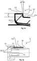
- Figures 3 to 4b show an embodiment of the support sleeve 6 according to the invention.
- the support sleeve 6 has in particular one or more radially elastic tabs 12 extending in the direction of insertion E and protruding radially outwards from the cylindrical outer surface 6a of the support sleeve 6 with a spreading height H to the direction of insertion.
- the pipeline 2 to be inserted is pushed onto the cylindrical outer surface 6a of the support sleeve 6 by means of an assembly force, the tabs 12, depending on their spread height H and a pipe inner diameter of the line 2 to be inserted, radially outward against an inner peripheral surface of the line 2 to be inserted to press.
- the Abab Soniere H at the end of a lever arm L of the tab 12 is preferably half a tolerance of an inner diameter of the to be inserted Pipeline 2 and acts as a tolerance compensation. Tolerance compensation ensures that the insertion is made in such a way that production-related tolerances of the pipeline 2 to be inserted are compensated for and the tab 12 rests against the inner diameter of the pipeline 2, regardless of whether the pipeline has a minimum diameter or a maximum diameter within the manufacturing tolerances.
- Figure 4b shows a practical embodiment of a lug 12 particularly adapted to a specific type of pipe.
- the tab 12 in Figure 4b has a radius R min at the front end of the lug 12 viewed in the insertion direction E, which is designed in particular for the production-related smallest tolerance of the pipeline 2, and viewed in the insertion direction E at the rear end of the lug 12 has a radius R max which is advantageous is designed for the production-related maximum tolerance of the pipeline 2.
- Figure 5a shows in this regard a pipeline 2 with a maximum internal diameter.
- the expansion causes the pipeline 2, despite a production-related increased inner diameter compared to the pipeline in Figure 5b , is securely in contact with the support sleeve 6, in particular the tabs 12.
- Figure 5b represents a pipeline 2 with a minimum inner diameter. If the pipeline 2 is moved in the insertion direction E in example 5b, the elastic tabs 12 pivot radially inwards and allow the axial movement of the pipeline 2 in the insertion direction E, with the tabs 12 in particular always making contact of pipeline 2 have.
- the total tolerance is calculated at 0.6 mm.
- the effect described above is ensured by a radial spreading height H of 0.3 mm of the tab 12 .
- a locking of the pipeline 2 during and after the insertion process is particularly advantageous for a constantly guaranteed contact between the support sleeve 6 and the pipeline 2 .
- the sensor element 10, in particular a projection 11 according to Figure 4c a sudden increase in Insertion resistance generated depending on the insertion depth of the line end 2a in the insertion direction E behind the peripheral seal 8 within the connector body 4.
- the sensor element 10 is arranged in particular on at least one free end, advantageously with the lever arm L, on the outer circumference of at least one tab 12, with the sensor element 10 preferably being designed as a radially outward-pointing projection 11.
- the projection 11 at the end of the tab 12 captures the sensor element 10 in its entirety from the line end 2a when the pipeline 2 is inserted in the insertion direction.
- the second haptic signal ie the second insertion resistance
- the second haptic signal can be influenced by the extent of the lever arm L and the elasticity of the tab.
- low elasticity and a short lever arm L increase the second insertion resistance.
- the distance between the first haptic signal of the peripheral seal 8 and the sensor element 10, in particular the projection 11 can be adjusted to the application-related needs in a user-friendly manner.
- the support sleeve 6 can have in particular three tabs 12, with each tab 12 preferably having a respective sensor element 10, in particular a projection 11.
- the number of tabs 12 and in particular the sensor elements 10 or the projections 11 has a direct influence on the second haptic signal in that the effect described above can be intensified with an increasing number of tabs 12 .
- three tabs 12 distributed evenly over the circumference of the support sleeve 6 in order to create a centrality when inserting the pipeline 2.
- the projection 11 has in particular a first projection surface 11a, which extends in particular at an angle Z to a plane perpendicular to the longitudinal axis XX of the connecting device 1 radially outer peripheral surface 12a of the tab 12 extends radially outwards and preferably represents a stop that can be overcome in the insertion direction E for the line end 2a.
- the pipeline 2 is first pushed over the cylindrical outer surface 6a of the support sleeve 6 to the area from which the support sleeve 6 has arranged one or more tabs 12 during the insertion process, the tabs 12 additionally having outer peripheral surfaces 12a.
- the pipeline 2 slides further over the outer peripheral surfaces 12a of the lugs 12, as a result of which the line end 2a is guided in particular directly against the projection 11, preferably against its first projection surface 11a. If the line end 2a butts against the first projection surface 11a, the second haptic signal is generated, ie the insertion resistance is suddenly increased.
- the angle Z makes it possible to influence the insertion resistance as well as its rate of increase, so an increase in the angle Z causes the line end 2a to overcome the projection 11 more easily, whereby the insertion resistance is lower and the rate of increase is flatter.
- the projection 11 can preferably have a second projection surface 11b, which extends in particular in the insertion direction E and advantageously adjoins the first projection surface 11a, the second projection surface 11b being offset radially outwards at a distance Y from the tab 12.
- the radial extent of the first protruding surface 11a can be influenced by the distance Y between the second protruding surface 11b, which in particular influences the insertion resistance of the second haptic signal.
- transition U1 from the outer peripheral surface 12a of the tab 12 to the first projection surface 11a of the projection 11 has a radius. This advantageously flattens the rate of increase of the second haptic signal and protects the material of the line 2 in the area of the line end 2a.
- the transition U2 from the first projection surface 11a to the second projection surface 11b has a radius. Further reduced there is a risk that the line end 2a will damage the sensor element 10 when overcoming the projection or will itself be damaged by a sharp-edged transition, as a result of which particles can get loose and get into the system.
- the tabs 12 adjust the insertion resistance in front of the peripheral seal 8 in particular to a base value. This base value is influenced in particular by the inside diameter of the pipeline 2 and the bracing height H.
- the lever arm L From the ratio of the lever arm L to the bracing height H, it can also be set from which insertion depth the insertion resistance should be set to the base value.
- the base value sensitizes the user to the subsequent first and second haptic signal.
- Other factors with which the basic value can be adjusted are the number and the elasticity of the tabs 12 and the frictional resistance that arises from the contact of the outer peripheral surfaces 12a of the tabs 12 with the inner peripheral surface of the pipeline 2 .
- the support sleeve 6 forms, as in Figures 1a and 1b shown, in the insertion direction E behind the sensor element 10, in particular behind the projection 11, an insurmountable pipe stop 14.
- This pipe stop advantageously forms a final deepest possible insertion for the line end 2a and can be used in particular as an additional third haptic signal which gives the user additional security conveyed.
- the distance in the insertion direction E of the highest value of the first insertion resistance of the peripheral seal 8, the highest value of the second insertion resistance of the sensor element 10 and of the pipe stop 14 is preferably the same in each case.
- the highest value of the first insertion resistance of the peripheral seal 8 and the highest value of the second insertion resistance of the sensor element 10 are the same.
- a further advantageous embodiment provides that the support sleeve 6 is designed in particular as a one-piece molded part and the tabs 12 and the sensor element 10 or the projection 11 are advantageously molded on. Furthermore, the support sleeve 6 is preferably made of glass fiber material.
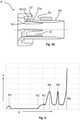
- FIG 6 shows an example of an advantageous progression of the assembly force F as a function of the insertion depth E for a connection device 1 according to the embodiment in FIG 1 .
- P1 in 6 denotes an increase in the assembly force F, which is required because of an increased insertion resistance, this insertion resistance being generated by an inner dirt seal 16 arranged in the receiving opening of the connection body 6 .
- P2 in 6 indicates the insertion depth from which the holding element 5, in particular a spring-elastic toothed ring, engages in the pipeline 2 for fixing the inserted line end 2a.
- the insertion depth P3 characterizes the point at which the line end 2a hits the elastic tabs 12, the tolerance compensation taking place at this point.
- the insertion resistance decreases again after P4 to the intermediate resistance, which is greater than the resistance value immediately in front of the peripheral seal 8.
- P5 in 6 P4 is similar to the peak of a sudden increase in the assembly force F, which is caused by the second haptic signal of the sensor element 10 or as in FIG 1 shown the projection 11, ie the second sudden increase in the insertion resistance is generated.
- the insertion resistance decreases again to the intermediate resistance after P5.
- the line end 2a has reached a pipe stop 14, which is advantageously designed on the support sleeve 6. If the user has noticed this assembly force profile or this insertion resistance profile in particular, he can assume that the pipeline 2 has been correctly inserted.
- the distance in the insertion direction E of the highest value of the first insertion resistance at P4 of the peripheral seal 8 and the highest value of the second insertion resistance at P5 of the sensor element 10 and the distance to the pipe stop 14 at P6 are each the same. Furthermore, in particular, the highest value of the first insertion resistance at P4 of the peripheral seal 8 and the highest value of the second insertion resistance at P5 are the same.
Landscapes
- Engineering & Computer Science (AREA)
- General Engineering & Computer Science (AREA)
- Mechanical Engineering (AREA)
- Quick-Acting Or Multi-Walled Pipe Joints (AREA)
Applications Claiming Priority (1)
| Application Number | Priority Date | Filing Date | Title |
|---|---|---|---|
| DE102018122732.9A DE102018122732A1 (de) | 2018-09-17 | 2018-09-17 | "Anschlussvorrichtung für Rohrleitungen" |
Publications (2)
| Publication Number | Publication Date |
|---|---|
| EP3623680A1 EP3623680A1 (de) | 2020-03-18 |
| EP3623680B1 true EP3623680B1 (de) | 2022-03-09 |
Family
ID=67659618
Family Applications (1)
| Application Number | Title | Priority Date | Filing Date |
|---|---|---|---|
| EP19192744.1A Active EP3623680B1 (de) | 2018-09-17 | 2019-08-21 | Anschlussvorrichtung für rohrleitungen |
Country Status (3)
| Country | Link |
|---|---|
| EP (1) | EP3623680B1 (pl) |
| DE (1) | DE102018122732A1 (pl) |
| PL (1) | PL3623680T3 (pl) |
Families Citing this family (2)
| Publication number | Priority date | Publication date | Assignee | Title |
|---|---|---|---|---|
| DE102020119002B3 (de) | 2020-07-17 | 2021-12-30 | Poloplast Gmbh & Co. Kg | Rohrmuffe |
| FR3153122A1 (fr) | 2023-09-14 | 2025-03-21 | Saint-Gobain Pam Canalisation | Dispositif de pose de tuyaux avec moyens de contrôle, ensemble et procédé correspondants |
Family Cites Families (8)
| Publication number | Priority date | Publication date | Assignee | Title |
|---|---|---|---|---|
| DE8712299U1 (de) * | 1987-09-10 | 1987-11-05 | Armaturenfabrik Hermann Voss GmbH + Co, 5272 Wipperfürth | Steckverbindung für Druckluftrohrleitungen aus Kunststoff |
| FR2830071B1 (fr) * | 2001-09-21 | 2003-11-14 | Legris Sa | Dispositif de raccordement instantane |
| JP4444878B2 (ja) * | 2005-05-20 | 2010-03-31 | 株式会社Inax | 配管継手 |
| GB2452038B (en) * | 2007-08-20 | 2012-05-02 | Wavin Bv | Push-fit pipe fitting system |
| EP2217843B1 (en) * | 2007-11-28 | 2011-09-21 | Kongsberg Automotive AS | Tube coupling system |
| EP2508784B1 (en) * | 2011-04-08 | 2014-01-08 | Aronkasei CO., LTD. | Pipe Coupling |
| DE202012102342U1 (de) | 2012-06-26 | 2013-10-02 | Voss Automotive Gmbh | Anschlussvorrichtung für Rohrleitungen |
| EP2949984A4 (en) * | 2012-11-07 | 2016-11-16 | Hita Technology Of Plastic System S L | QUICK COUPLING FOR PIPES |
-
2018
- 2018-09-17 DE DE102018122732.9A patent/DE102018122732A1/de active Pending
-
2019
- 2019-08-21 PL PL19192744.1T patent/PL3623680T3/pl unknown
- 2019-08-21 EP EP19192744.1A patent/EP3623680B1/de active Active
Also Published As
| Publication number | Publication date |
|---|---|
| PL3623680T3 (pl) | 2022-08-08 |
| DE102018122732A1 (de) | 2020-03-19 |
| EP3623680A1 (de) | 2020-03-18 |
Similar Documents
| Publication | Publication Date | Title |
|---|---|---|
| DE112006004024B4 (de) | Montagewerkzeug für eine Anschlussvorrichtung für Medienleitungen | |
| EP1697675B1 (de) | Steckverbinder für medienleitungen | |
| EP1543267B1 (de) | Anschlussvorrichtung für rohrleitungen | |
| EP3441657B1 (de) | Anschlussvorrichtung für rohrleitungen mit leckageanzeige | |
| EP0816741A2 (de) | Einsteckkupplung | |
| DE102006013899B3 (de) | Steckkupplung | |
| DE202012102342U1 (de) | Anschlussvorrichtung für Rohrleitungen | |
| DE102012108791A1 (de) | Bausystem für eine Anschlussvorrichtung für Medienleitungen | |
| DE102015118314A1 (de) | Verfahren zum Befestigen eines Befestigungselements an einer Montageschiene sowie Befestigungselement | |
| EP0899498A2 (de) | Steckkupplung | |
| EP2283268B1 (de) | Steckkupplung für druckmittel-leitungen | |
| WO2017144570A1 (de) | Befestigungsstecker, anbauteilbaugruppe, befestigungsanordnung | |
| EP3623680B1 (de) | Anschlussvorrichtung für rohrleitungen | |
| EP2165104A1 (de) | Ladeluftschlauch | |
| EP3850260B1 (de) | Anschlussvorrichtung für rohrleitungen mit leckageanzeige | |
| DE102015110124A1 (de) | Anschlussvorrichtung zum lösbaren Anschluss von Kunststoff-Rohrleitungen | |
| EP0733845B1 (de) | Anschlussvorrichtung zum Anschluss von Rohrleitungen an ein Aggregateteil | |
| DE102005044751B4 (de) | Steckverbinder für Medienleitungen | |
| DE102008020833A1 (de) | Pressverbindung | |
| DE19625687C2 (de) | Einsteckkupplung | |
| EP3361135A1 (de) | Schnellverbindungsvorrichtung und schnellverbindungssystem | |
| EP3497358B1 (de) | Anschlussvorrichtung für rohrleitungen mit leckageanzeige | |
| DE102021107913A1 (de) | "Anschlussvorrichtung für Rohrleitungen mit Leckageanzeige" | |
| DE102006026162B4 (de) | Anschlussvorrichtung für Medienleitungen | |
| EP1882875B1 (de) | Steckmuffe zum Verbinden von Rohren |
Legal Events
| Date | Code | Title | Description |
|---|---|---|---|
| PUAI | Public reference made under article 153(3) epc to a published international application that has entered the european phase |
Free format text: ORIGINAL CODE: 0009012 |
|
| STAA | Information on the status of an ep patent application or granted ep patent |
Free format text: STATUS: THE APPLICATION HAS BEEN PUBLISHED |
|
| AK | Designated contracting states |
Kind code of ref document: A1 Designated state(s): AL AT BE BG CH CY CZ DE DK EE ES FI FR GB GR HR HU IE IS IT LI LT LU LV MC MK MT NL NO PL PT RO RS SE SI SK SM TR |
|
| AX | Request for extension of the european patent |
Extension state: BA ME |
|
| STAA | Information on the status of an ep patent application or granted ep patent |
Free format text: STATUS: REQUEST FOR EXAMINATION WAS MADE |
|
| 17P | Request for examination filed |
Effective date: 20200519 |
|
| RBV | Designated contracting states (corrected) |
Designated state(s): AL AT BE BG CH CY CZ DE DK EE ES FI FR GB GR HR HU IE IS IT LI LT LU LV MC MK MT NL NO PL PT RO RS SE SI SK SM TR |
|
| GRAP | Despatch of communication of intention to grant a patent |
Free format text: ORIGINAL CODE: EPIDOSNIGR1 |
|
| STAA | Information on the status of an ep patent application or granted ep patent |
Free format text: STATUS: GRANT OF PATENT IS INTENDED |
|
| INTG | Intention to grant announced |
Effective date: 20211015 |
|
| GRAS | Grant fee paid |
Free format text: ORIGINAL CODE: EPIDOSNIGR3 |
|
| GRAA | (expected) grant |
Free format text: ORIGINAL CODE: 0009210 |
|
| STAA | Information on the status of an ep patent application or granted ep patent |
Free format text: STATUS: THE PATENT HAS BEEN GRANTED |
|
| AK | Designated contracting states |
Kind code of ref document: B1 Designated state(s): AL AT BE BG CH CY CZ DE DK EE ES FI FR GB GR HR HU IE IS IT LI LT LU LV MC MK MT NL NO PL PT RO RS SE SI SK SM TR |
|
| REG | Reference to a national code |
Ref country code: CH Ref legal event code: EP Ref country code: AT Ref legal event code: REF Ref document number: 1474441 Country of ref document: AT Kind code of ref document: T Effective date: 20220315 |
|
| REG | Reference to a national code |
Ref country code: DE Ref legal event code: R096 Ref document number: 502019003630 Country of ref document: DE |
|
| REG | Reference to a national code |
Ref country code: IE Ref legal event code: FG4D Free format text: LANGUAGE OF EP DOCUMENT: GERMAN |
|
| REG | Reference to a national code |
Ref country code: LT Ref legal event code: MG9D |
|
| REG | Reference to a national code |
Ref country code: NL Ref legal event code: MP Effective date: 20220309 |
|
| PG25 | Lapsed in a contracting state [announced via postgrant information from national office to epo] |
Ref country code: SE Free format text: LAPSE BECAUSE OF FAILURE TO SUBMIT A TRANSLATION OF THE DESCRIPTION OR TO PAY THE FEE WITHIN THE PRESCRIBED TIME-LIMIT Effective date: 20220309 Ref country code: RS Free format text: LAPSE BECAUSE OF FAILURE TO SUBMIT A TRANSLATION OF THE DESCRIPTION OR TO PAY THE FEE WITHIN THE PRESCRIBED TIME-LIMIT Effective date: 20220309 Ref country code: NO Free format text: LAPSE BECAUSE OF FAILURE TO SUBMIT A TRANSLATION OF THE DESCRIPTION OR TO PAY THE FEE WITHIN THE PRESCRIBED TIME-LIMIT Effective date: 20220609 Ref country code: LT Free format text: LAPSE BECAUSE OF FAILURE TO SUBMIT A TRANSLATION OF THE DESCRIPTION OR TO PAY THE FEE WITHIN THE PRESCRIBED TIME-LIMIT Effective date: 20220309 Ref country code: HR Free format text: LAPSE BECAUSE OF FAILURE TO SUBMIT A TRANSLATION OF THE DESCRIPTION OR TO PAY THE FEE WITHIN THE PRESCRIBED TIME-LIMIT Effective date: 20220309 Ref country code: BG Free format text: LAPSE BECAUSE OF FAILURE TO SUBMIT A TRANSLATION OF THE DESCRIPTION OR TO PAY THE FEE WITHIN THE PRESCRIBED TIME-LIMIT Effective date: 20220609 |
|
| PG25 | Lapsed in a contracting state [announced via postgrant information from national office to epo] |
Ref country code: LV Free format text: LAPSE BECAUSE OF FAILURE TO SUBMIT A TRANSLATION OF THE DESCRIPTION OR TO PAY THE FEE WITHIN THE PRESCRIBED TIME-LIMIT Effective date: 20220309 Ref country code: GR Free format text: LAPSE BECAUSE OF FAILURE TO SUBMIT A TRANSLATION OF THE DESCRIPTION OR TO PAY THE FEE WITHIN THE PRESCRIBED TIME-LIMIT Effective date: 20220610 Ref country code: FI Free format text: LAPSE BECAUSE OF FAILURE TO SUBMIT A TRANSLATION OF THE DESCRIPTION OR TO PAY THE FEE WITHIN THE PRESCRIBED TIME-LIMIT Effective date: 20220309 |
|
| PG25 | Lapsed in a contracting state [announced via postgrant information from national office to epo] |
Ref country code: NL Free format text: LAPSE BECAUSE OF FAILURE TO SUBMIT A TRANSLATION OF THE DESCRIPTION OR TO PAY THE FEE WITHIN THE PRESCRIBED TIME-LIMIT Effective date: 20220309 |
|
| PG25 | Lapsed in a contracting state [announced via postgrant information from national office to epo] |
Ref country code: SM Free format text: LAPSE BECAUSE OF FAILURE TO SUBMIT A TRANSLATION OF THE DESCRIPTION OR TO PAY THE FEE WITHIN THE PRESCRIBED TIME-LIMIT Effective date: 20220309 Ref country code: SK Free format text: LAPSE BECAUSE OF FAILURE TO SUBMIT A TRANSLATION OF THE DESCRIPTION OR TO PAY THE FEE WITHIN THE PRESCRIBED TIME-LIMIT Effective date: 20220309 Ref country code: RO Free format text: LAPSE BECAUSE OF FAILURE TO SUBMIT A TRANSLATION OF THE DESCRIPTION OR TO PAY THE FEE WITHIN THE PRESCRIBED TIME-LIMIT Effective date: 20220309 Ref country code: PT Free format text: LAPSE BECAUSE OF FAILURE TO SUBMIT A TRANSLATION OF THE DESCRIPTION OR TO PAY THE FEE WITHIN THE PRESCRIBED TIME-LIMIT Effective date: 20220711 Ref country code: ES Free format text: LAPSE BECAUSE OF FAILURE TO SUBMIT A TRANSLATION OF THE DESCRIPTION OR TO PAY THE FEE WITHIN THE PRESCRIBED TIME-LIMIT Effective date: 20220309 Ref country code: EE Free format text: LAPSE BECAUSE OF FAILURE TO SUBMIT A TRANSLATION OF THE DESCRIPTION OR TO PAY THE FEE WITHIN THE PRESCRIBED TIME-LIMIT Effective date: 20220309 Ref country code: CZ Free format text: LAPSE BECAUSE OF FAILURE TO SUBMIT A TRANSLATION OF THE DESCRIPTION OR TO PAY THE FEE WITHIN THE PRESCRIBED TIME-LIMIT Effective date: 20220309 |
|
| PG25 | Lapsed in a contracting state [announced via postgrant information from national office to epo] |
Ref country code: IS Free format text: LAPSE BECAUSE OF FAILURE TO SUBMIT A TRANSLATION OF THE DESCRIPTION OR TO PAY THE FEE WITHIN THE PRESCRIBED TIME-LIMIT Effective date: 20220709 Ref country code: AL Free format text: LAPSE BECAUSE OF FAILURE TO SUBMIT A TRANSLATION OF THE DESCRIPTION OR TO PAY THE FEE WITHIN THE PRESCRIBED TIME-LIMIT Effective date: 20220309 |
|
| REG | Reference to a national code |
Ref country code: DE Ref legal event code: R097 Ref document number: 502019003630 Country of ref document: DE |
|
| PLBE | No opposition filed within time limit |
Free format text: ORIGINAL CODE: 0009261 |
|
| STAA | Information on the status of an ep patent application or granted ep patent |
Free format text: STATUS: NO OPPOSITION FILED WITHIN TIME LIMIT |
|
| PG25 | Lapsed in a contracting state [announced via postgrant information from national office to epo] |
Ref country code: DK Free format text: LAPSE BECAUSE OF FAILURE TO SUBMIT A TRANSLATION OF THE DESCRIPTION OR TO PAY THE FEE WITHIN THE PRESCRIBED TIME-LIMIT Effective date: 20220309 |
|
| 26N | No opposition filed |
Effective date: 20221212 |
|
| PG25 | Lapsed in a contracting state [announced via postgrant information from national office to epo] |
Ref country code: SI Free format text: LAPSE BECAUSE OF FAILURE TO SUBMIT A TRANSLATION OF THE DESCRIPTION OR TO PAY THE FEE WITHIN THE PRESCRIBED TIME-LIMIT Effective date: 20220309 |
|
| PG25 | Lapsed in a contracting state [announced via postgrant information from national office to epo] |
Ref country code: MC Free format text: LAPSE BECAUSE OF FAILURE TO SUBMIT A TRANSLATION OF THE DESCRIPTION OR TO PAY THE FEE WITHIN THE PRESCRIBED TIME-LIMIT Effective date: 20220309 |
|
| REG | Reference to a national code |
Ref country code: CH Ref legal event code: PL |
|
| PG25 | Lapsed in a contracting state [announced via postgrant information from national office to epo] |
Ref country code: LU Free format text: LAPSE BECAUSE OF NON-PAYMENT OF DUE FEES Effective date: 20220821 Ref country code: LI Free format text: LAPSE BECAUSE OF NON-PAYMENT OF DUE FEES Effective date: 20220831 Ref country code: CH Free format text: LAPSE BECAUSE OF NON-PAYMENT OF DUE FEES Effective date: 20220831 |
|
| REG | Reference to a national code |
Ref country code: BE Ref legal event code: MM Effective date: 20220831 |
|
| P01 | Opt-out of the competence of the unified patent court (upc) registered |
Effective date: 20230526 |
|
| PG25 | Lapsed in a contracting state [announced via postgrant information from national office to epo] |
Ref country code: IT Free format text: LAPSE BECAUSE OF FAILURE TO SUBMIT A TRANSLATION OF THE DESCRIPTION OR TO PAY THE FEE WITHIN THE PRESCRIBED TIME-LIMIT Effective date: 20220309 Ref country code: IE Free format text: LAPSE BECAUSE OF NON-PAYMENT OF DUE FEES Effective date: 20220821 |
|
| PG25 | Lapsed in a contracting state [announced via postgrant information from national office to epo] |
Ref country code: BE Free format text: LAPSE BECAUSE OF NON-PAYMENT OF DUE FEES Effective date: 20220831 |
|
| PG25 | Lapsed in a contracting state [announced via postgrant information from national office to epo] |
Ref country code: HU Free format text: LAPSE BECAUSE OF FAILURE TO SUBMIT A TRANSLATION OF THE DESCRIPTION OR TO PAY THE FEE WITHIN THE PRESCRIBED TIME-LIMIT; INVALID AB INITIO Effective date: 20190821 |
|
| GBPC | Gb: european patent ceased through non-payment of renewal fee |
Effective date: 20230821 |
|
| PG25 | Lapsed in a contracting state [announced via postgrant information from national office to epo] |
Ref country code: CY Free format text: LAPSE BECAUSE OF FAILURE TO SUBMIT A TRANSLATION OF THE DESCRIPTION OR TO PAY THE FEE WITHIN THE PRESCRIBED TIME-LIMIT Effective date: 20220309 |
|
| PG25 | Lapsed in a contracting state [announced via postgrant information from national office to epo] |
Ref country code: MK Free format text: LAPSE BECAUSE OF FAILURE TO SUBMIT A TRANSLATION OF THE DESCRIPTION OR TO PAY THE FEE WITHIN THE PRESCRIBED TIME-LIMIT Effective date: 20220309 |
|
| PG25 | Lapsed in a contracting state [announced via postgrant information from national office to epo] |
Ref country code: TR Free format text: LAPSE BECAUSE OF FAILURE TO SUBMIT A TRANSLATION OF THE DESCRIPTION OR TO PAY THE FEE WITHIN THE PRESCRIBED TIME-LIMIT Effective date: 20220309 |
|
| PG25 | Lapsed in a contracting state [announced via postgrant information from national office to epo] |
Ref country code: GB Free format text: LAPSE BECAUSE OF NON-PAYMENT OF DUE FEES Effective date: 20230821 |
|
| PG25 | Lapsed in a contracting state [announced via postgrant information from national office to epo] |
Ref country code: GB Free format text: LAPSE BECAUSE OF NON-PAYMENT OF DUE FEES Effective date: 20230821 |
|
| PG25 | Lapsed in a contracting state [announced via postgrant information from national office to epo] |
Ref country code: MT Free format text: LAPSE BECAUSE OF FAILURE TO SUBMIT A TRANSLATION OF THE DESCRIPTION OR TO PAY THE FEE WITHIN THE PRESCRIBED TIME-LIMIT Effective date: 20220309 |
|
| PGFP | Annual fee paid to national office [announced via postgrant information from national office to epo] |
Ref country code: PL Payment date: 20250703 Year of fee payment: 7 |
|
| REG | Reference to a national code |
Ref country code: AT Ref legal event code: MM01 Ref document number: 1474441 Country of ref document: AT Kind code of ref document: T Effective date: 20240821 |
|
| PG25 | Lapsed in a contracting state [announced via postgrant information from national office to epo] |
Ref country code: AT Free format text: LAPSE BECAUSE OF NON-PAYMENT OF DUE FEES Effective date: 20240821 |
|
| PGFP | Annual fee paid to national office [announced via postgrant information from national office to epo] |
Ref country code: FR Payment date: 20250707 Year of fee payment: 7 |
|
| PGFP | Annual fee paid to national office [announced via postgrant information from national office to epo] |
Ref country code: DE Payment date: 20251023 Year of fee payment: 7 |
|
| PGFP | Annual fee paid to national office [announced via postgrant information from national office to epo] |
Ref country code: AT Payment date: 20260410 Year of fee payment: 5 |