EP3623741B1 - Unité de tir pour munition - Google Patents
Unité de tir pour munition Download PDFInfo
- Publication number
- EP3623741B1 EP3623741B1 EP19193103.9A EP19193103A EP3623741B1 EP 3623741 B1 EP3623741 B1 EP 3623741B1 EP 19193103 A EP19193103 A EP 19193103A EP 3623741 B1 EP3623741 B1 EP 3623741B1
- Authority
- EP
- European Patent Office
- Prior art keywords
- sleeve
- launching unit
- cap
- spring tensioner
- spring
- Prior art date
- Legal status (The legal status is an assumption and is not a legal conclusion. Google has not performed a legal analysis and makes no representation as to the accuracy of the status listed.)
- Active
Links
Images


Classifications
-
- F—MECHANICAL ENGINEERING; LIGHTING; HEATING; WEAPONS; BLASTING
- F41—WEAPONS
- F41C—SMALLARMS, e.g. PISTOLS, RIFLES; ACCESSORIES THEREFOR
- F41C3/00—Pistols, e.g. revolvers
- F41C3/02—Signal pistols, e.g. Very pistols
-
- F—MECHANICAL ENGINEERING; LIGHTING; HEATING; WEAPONS; BLASTING
- F42—AMMUNITION; BLASTING
- F42C—AMMUNITION FUZES; ARMING OR SAFETY MEANS THEREFOR
- F42C15/00—Arming-means in fuzes; Safety means for preventing premature detonation of fuzes or charges
- F42C15/20—Arming-means in fuzes; Safety means for preventing premature detonation of fuzes or charges wherein a securing-pin or latch is removed to arm the fuze, e.g. removed from the firing-pin
-
- F—MECHANICAL ENGINEERING; LIGHTING; HEATING; WEAPONS; BLASTING
- F42—AMMUNITION; BLASTING
- F42C—AMMUNITION FUZES; ARMING OR SAFETY MEANS THEREFOR
- F42C15/00—Arming-means in fuzes; Safety means for preventing premature detonation of fuzes or charges
- F42C15/44—Arrangements for disarming, or for rendering harmless, fuzes after arming, e.g. after launch
Definitions
- the invention relates to a launching unit for ammunition, in particular for a signal rocket, comprising a clamping sleeve, a striking element mounted axially movably within the clamping sleeve, a tensioning element for tensioning the striking element and a pulling element connected to the striking element.
- launching units for hand-held signal rockets can basically be divided into three different types, namely launching units with breakaway ignition, with lever release or with rotary handle.
- the ammunition is ignited by triggering the launch unit.
- a disadvantage of systems with lever release is that the operator warps the signal rocket when it is released and thus shoots in an undirected manner. Furthermore, reversibility is no longer given if the cover cap is lost. The lever of the launcher is then freely movable and therefore unsecured and open.
- the firing pin In systems with rotary ignition, the firing pin is cocked by means of a rotary movement and ignition is initiated. Due to the rotary movement as a trigger mechanism, however, there is a risk of tearing, as there is no directed axial firing in the direction of the shot. This design is comparatively complex to manufacture.
- the DE 1 254 509 discloses a signal rocket with a detonator.
- the detonator is designed in such a way that an ignition device is accommodated in the base plate of the signal rocket and this is directly connected with a cord.
- the cord is in turn connected to a cap, so that the signal rocket is triggered by tearing off the cap.
- EP 0 277 275 B1 DE 10 2007 015 248 A1 and from EP 0 679 860 B1 known.
- a cord secured with a cap for actuating the signal rocket is designed on the bottom of the signal rocket.
- the cord is connected to a firing pin which is guided within a clamping sleeve. If the cord is actuated, the firing pin is tensioned by means of a spring attached to the clamping sleeve and then released by tearing the cord, so that the firing pin strikes a detonator and triggers it.
- the device has a release and safety mechanism which has a protective sleeve with a locking ring.
- the locking ring is attached to the head of the protective sleeve and secures a sliding button. If the safety ring is unlocked, the slide button can be operated to trigger the launching device.
- a drawstring is provided on the sliding button that extends to the bottom of the protective sleeve.
- a firing pin pretensioned by a spring is provided in a groove, which can be released by means of the slide button.
- the disadvantage here is that the firing pin is always tensioned by the spring and only secured. Unintentional triggering is possible due to the principle. Since the spring is permanently tensioned, the spring force decreases and at some point is no longer sufficient to transfer enough energy to the firing pin and enable safe ignition.
- From the DE 1 553 893 is a signal cartridge that triggers in response to a combined rotary and push-in movement, known.
- a firing device for a signal rocket which has a tubular detachable housing and, after the housing has been removed, can be actuated by means of a trigger pin which can be actuated by the thumb.
- a pyrotechnic signaling means with an ignition device which has a breakaway ignition.
- the igniter comprises a base and a bottom part.
- the bottom part is connected to the base and serves to receive a primer cap.
- the base supports a firing pin which can be preloaded with respect to the base by means of a spring.
- the firing pin is connected to a pulling element which releases the firing pin after a certain deflection.
- the invention is based on the object of creating a launching unit with improved handling that is reversible.
- a launching unit for ammunition in particular a signal rocket, preferably a hand-held signal rocket, is created which comprises a clamping sleeve, a striking element mounted axially movably within the clamping sleeve, a tensioning element for tensioning the striking element and a pulling element connected to the striking element.
- the pulling element is designed to be telescopic. That is, the pulling element can be pulled apart or pushed together.
- the direction of movement is specified by the telescopic ability of the pulling element.
- This lies with the firing direction - i.e. the direction of the axis of the striking element and the clamping sleeve - on a common axis, so that undirected pulling is no longer possible.
- the pulling element can be secured so that it has to be unlocked before telescoping. Before telescoping, the pulling element is in a rest position. By pulling on the pulling element, it is telescoped and the telescopic mechanism is extended. In this extended or telescoped state, the firing unit is in a secured and ready-to-fire state. The striking element is not yet deflected in this position. By further pulling on the pulling element, the striking element connected to the pulling element can be deflected and the tensioning element biases it against the deflection before it is released by further deflecting the pulling element and triggers the firing unit.
- an axial movement in the weft direction is thus provided.
- the ammunition is also fired in this axial direction.
- tearing due to undirected pulling is no longer possible.
- the telescopic design of the pulling element specifies the direction of movement of the release.
- the firing unit is reversible in that the pulling element is designed to be telescopic.
- the pulling element can thus be telescoped out of the rest position into a position that is ready for fire, but it can also be telescoped back in from the position that is ready for fire into the position of rest. After returning to this rest position, it can be provided that the pulling element can be secured again in this rest position. Reversibility is provided by the fact that the pulling element can be telescoped back into a safe initial state. Furthermore, since the pulling element is designed to be telescopic, the individual parts of the pulling element can no longer be lost.
- the tensioning element can be a spring.
- the pulling element can be designed in two parts, the pulling element having a spring tensioner connected to the striking element and one to the Comprising spring tensioner telescopically arranged cap.
- the spring tensioner is the component of the pulling element that is connected to the striking element.
- the cap is provided so that it can be telescoped to the spring tensioner. This can be extended and retracted in relation to the spring tensioner. It can also be provided that the cap can be secured in the retracted position.
- the cap serves, on the one hand, to shield the spring tensioner from the outside and, on the other hand, to actuate it after telescoping.
- the pulling element can also be designed in more than two parts, for example three-part, four-part, etc.
- the spring is attached to the circumferential side of the clamping sleeve. This means that no additional installation space has to be created for the spring within the clamping sleeve, but rather this is simply pushed onto the circumferential side of the clamping sleeve.
- the dimensioning of the spring is therefore not linked to the space available within the clamping sleeve in which the striking element is also arranged. Accordingly, it is possible that more space is available for dimensioning the spring.
- the spring tensioner has a longitudinal slot.
- the clamping sleeve has at least one sleeve slot.
- the striking element can be a flat element and have at least one projection or hook. The projection or the hook can extend through the longitudinal slot. Furthermore, the projection or the hook can extend through the sleeve slot. The protrusion or the hook can be engaged with the spring.
- the spring tensioner has a longitudinal slot, it can receive the striking element in the longitudinal slot. It is also possible for the projection or the hook of the striking element to extend out of the spring tensioner. Since the clamping sleeve also has at least one sleeve slot which is essentially parallel to the slot of the spring tensioner, the projection or the hook of the striking element can extend out of the spring tensioner and through the sleeve slot of the tensioning sleeve to the outside of the tensioning sleeve, where it extends with the spring is engaged in such a way that the spring tensions the striking element when it is deflected from its rest position.
- the spring tensioner can be dimensioned in such a way that the spring tensioner expands elastically without radial counterpressure, so that the longitudinal slot becomes wider and the forces between the spring tensioner and striking element decrease.
- a spring tensioner with a longitudinal slot and a striking element which is designed as a flat element, a large contact area is created between the spring tensioner and striking element, which allows a good frictional connection to be established between these two elements, so that the spring tensioner is coupled to the striking pin is.
- the firing unit has a locking sleeve connected to the clamping sleeve.
- the invention can provide that the pulling element has a reversibly releasable lock for securing the pulling element.
- the securing sleeve and the cap have a reversibly releasable lock for securing the cap on the securing sleeve.
- the reversibly releasable closure ensures that the cap can be released from the locking sleeve and then secured again.
- the term "reversibly releasable" means that the closure or the cap can be released non-destructively and then secured again. It is thus possible to transfer the firing unit into a ready-to-fire and secured state and then to reverse this again and to secure the cap in such a way that the firing unit can be stowed away again and used for any later use.
- the reversibly releasable closure is a screw closure.
- the lock is a bayonet lock.
- the cap has a thread and the securing sleeve has a thread, as a result of which the cap is connected to the securing sleeve in a reversibly releasable manner.
- the cap can preferably have an internal thread and the securing sleeve an external thread.
- the spring tensioner has a guide area with a transverse bore. Furthermore, it can be provided that the striking element has a bore and an intermediate element is arranged in the transverse bore and the bore.
- the intermediate element can preferably be a sphere.
- the bore is arranged at a distance from the head of the spring tensioner by a first section.
- the intermediate element can be arranged in the transverse bore and the bore in such a way that when the spring tensioner is pulled out of the clamping sleeve around the first section, the intermediate element is released.
- the spring tensioner has a guide area with a circumferential groove.
- an intermediate element can be arranged between the inner wall of the clamping sleeve and the groove. This is done in order to preload the spring tensioner radially in such a way that the striking element, which is arranged in the longitudinal slot of the spring tensioner, is connected to the spring tensioner in a non-positive, in particular frictional manner.
- the spring tensioner can be dimensioned in such a way that the spring tensioner expands elastically without radial counterpressure, so that the longitudinal slot becomes wider and the forces between the spring tensioner and striking element decrease.
- the groove is arranged at a distance from the head of the spring tensioner by a first section.
- the intermediate element is arranged between the groove and the inner wall of the clamping sleeve.
- the intermediate element can be released so that the frictional connection, in particular the frictional connection, between the spring tensioner and impact element can be reduced or canceled in such a way that the impact element is released.
- the spring tensioner has a pin.
- the cap can have at least one, preferably two, three or four webs, each with a holding element, which are designed such that the cap can be displaced along the pin of the spring tensioner. This ensures, on the one hand, that the cap is secured to the pin of the spring tensioner and, on the other hand, it ensures that it can be easily assembled with the spring tensioner and then does not come off unintentionally after assembly.
- the pin has a pin base which is shaped such that it forms a stop for the holding elements.
- a primer cap holder connected to the clamping sleeve is arranged above the clamping sleeve.
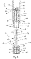
- a launching unit 1 for ammunition in particular a signal rocket, according to an exemplary embodiment of the invention is shown in schematic sectional views.
- the firing unit 1 comprises a clamping sleeve 30 and an impact element 90 mounted axially movably within the clamping sleeve 30. Furthermore, the firing unit 1 comprises a spring 20 as a tensioning element for tensioning the impact element 90 and a pulling element 2 connected to the striking element 90.
- the pulling element 2 is telescopic in two parts educated.
- the tension member 2 comprises a spring tensioner 10 and a cap 60 arranged telescopically relative to the spring tensioner 10.
- the spring tensioner 10 is an elongated component and comprises a pin 12 and a guide area 18.
- the guide area 18 of the spring tensioner 10 extends from a head 11 of the spring tensioner 10 downward.
- a stop 19 is formed below the guide area 18. This is designed in particular in the form of a plate 19.
- the pin 12 of the spring tensioner 10 adjoins below.
- the pin base 14 is formed.
- the guide area 18 has a first section 18.1 and a second section 18.2.
- the first section 18.1 extends from the head 11 of the pin 18 to a transverse bore 17 of the pin.
- the second section 18.2 of the guide area 18 adjoins below the transverse bore 17.
- the guide area 18 of the spring compressor 10 has a longitudinal slot 16. This extends downward from the head 11 of the spring tensioner 10 and serves to accommodate the impact element 90.
- the cap 60 is arranged telescopically relative to the spring tensioner 10.
- the cap 60 is slidably mounted on the pin 12 of the spring tensioner 10.
- the pin base 14 and the stop 19 limit the scope of movement of the cap 60 on the pin 12.
- the cap 60 has one or more webs 63, each of which has a holding element 64.
- the holding elements 64 are preferably designed as snap hooks.
- the pin base 14 has a bevel over which the holding elements 64 slide over when the cap 60 is mounted on the spring tensioner 10.
- the upper side of the cap 60 has an opening 66 and the lower side of the cap 60 has a bottom. Gripping elements 68 are formed on the side of the cap 60, which facilitate manual rotation of the cap 60.
- the launching unit 1 also has a clamping sleeve 30.
- the clamping sleeve 30 has an interior space with an essentially cylindrical inner wall 32.
- the outer wall of the clamping sleeve 30 is also essentially cylindrical.
- the spring 20 is pushed onto the clamping sleeve 30 on the circumferential side.
- a clamping sleeve flange 34 is formed on the bottom of the clamping sleeve 30.
- the clamping sleeve flange 34 forms a lower abutment for the spring 20.
- the clamping sleeve 30 is closed at the top by a head 38.
- the head 38 has a through hole 39, which is preferably formed in the middle.
- the clamping sleeve 30 has at least one sleeve slot 36.
- a primer cap holder 80 is arranged on the head 38 of the clamping sleeve 30.
- the percussion cap receptacle 80 is attached to the collet.
- the percussion cap receptacle 80 has a receptacle part 82 and one of the protruding portions 84.
- the receiving part 82 serves to receive a percussion cap 70.
- the percussion cap holder 80 fixes the percussion cap 70 in its position with respect to the clamping sleeve 30.
- the protruding section 84 also ensures that the spring 20 cannot slip off the clamping sleeve 30.
- the spring tensioner 10 has a longitudinal slot 16 and the clamping sleeve 30 has at least one sleeve slot 36.
- the striking element 90 is designed as a flat element and has at least one projection, preferably two Projections 92 on. The at least one projection 92 extends through the longitudinal slot 16 of the spring tensioner 10 and the sleeve slot 36 of the clamping sleeve 30 and is in engagement with the spring 20.
- the firing unit 1 has a locking sleeve 50 connected to the clamping sleeve 30.
- the locking sleeve 50 has a flange 54 with which the locking sleeve 50 is fastened to the clamping sleeve 30.
- the securing sleeve 50 also has a guide region 56. This is essentially tubular and extends downward from the flange 54 of the securing sleeve 50.
- the guide area 56 serves to provide a guide for the cap 60.
- the diameter of the guide region 56 is designed in such a way that it corresponds to an inner diameter of the cap 60. As a result, the cap 60 is given an additional guide, whereby a misjudged or jammed is prevented.
- the securing sleeve 50 and the cap 60 have a reversibly releasable lock 52, 62 for securing the cap 60 on the securing sleeve 50.
- the closure 52, 62 is a screw closure and is designed as follows.
- the cap 60 has a thread 52, in particular an internal thread
- the securing sleeve 50 has a thread 62, in particular an external thread.
- the cap 60 is reversibly detachably connected to the securing sleeve 50 by the closure 52, 62, which is designed as a screw closure.
- the spring tensioner 10 has a guide area 18 with a transverse bore 17.
- An intermediate element 15 is arranged between the inner wall 32 of the clamping sleeve 30 and in the transverse bore 17 and the bore 94 of the striking element.
- the intermediate element 15 is preferably a ball.
- the intermediate element 15 is provided in order to releasably connect the spring tensioner 10 to the striking element 90.
- the striking element 90 is connected to the spring tensioner 10, so that the striking pin 90, spring tensioner 10 and cap 60 form a unit which is designed to be axially movable with respect to the clamping sleeve 30.
- the transverse bore 17 of the spring tensioner 10 is arranged at a distance from the head 11 of the spring tensioner 10 by a first section 18.1.
- the intermediate element 15 is arranged in the transverse bore 17 and the bore 94 in such a way that when the spring tensioner 10 is pulled out of the clamping sleeve 30 around the first section 18.1, the intermediate element 15 is released so that the connection between the spring tensioner 10 and striking element 90 is canceled, so that the striking element 90 is released. If the spring tensioner 10 is pulled out of the clamping sleeve 30, the spring tensioner 10 takes the striking element 90 with it when the deflection of the spring tensioner 10 is smaller than the first section 18.1 and steers it out of its position Fig. 1 relaxed rest position shown.
- the spring 20 When it is deflected from the rest position, the spring 20 is tensioned by the striking element 90.
- the striking element 90 has at least one projection 92 or hook, which is connected to the spring 20 in such a way that it is pretensioned by deflecting the striking element 90 from the rest position.
- the striking element 90 At the moment when the deflection of the spring tensioner 10 is greater than the first section 18.1 and the groove 17 is pulled out of the clamping sleeve 30, the striking element 90 is released and accelerated in the direction of the primer cap 70 by the pretensioned spring.
- the striking element 90 has a striking piece that then snaps through the through hole 39 of the clamping sleeve and strikes the primer cap 70 with sufficient energy to trigger it.
- the energy which the striking element 90 transmits when it hits the primer cap 70 can be adjusted.
- the actual ignition of the ammunition is initiated by igniting the percussion cap 70.
- a launch sleeve 40 is also provided. This can either be part of the launching unit 1 on which the launching unit 1 is mounted.
- the launching sleeve 40 is connected on the one hand to the clamping sleeve 30 and on the other hand to the locking sleeve 50.
- the launching sleeve 40 is tubular and extends upward from the flange 54 of the locking sleeve 50 essentially parallel to the clamping sleeve 30.
- the launching sleeve 40 surrounds the clamping sleeve 30 and receives it together with the primer cap holder 80 and the components arranged on the clamping sleeve 30 in its interior.
- the ammunition to be fired is received in the firing case 40 above the primer cap.
- Fig. 1 shows in a schematic sectional view a firing unit according to an embodiment of the invention in a secured and not ready-to-fire position.
- the cap 60 is secured to the securing sleeve 50 by the closure 52, 62.
- the striking element 90 and the spring 20 are in their rest position, ie the spring is not tensioned.
- the firing unit 1 is thus in a safe state and cannot be accidentally triggered by impacts or unintentional tearing out of the pulling element 2.
- Fig. 2 shows in a schematic sectional view the in Fig. 1 Firing unit shown in an unlocked and ready-to-fire position.
- the cap 60 is no longer secured on the securing sleeve 50 by the closure 52, 62.
- the striking element 90 and the spring 20 are in their rest position. I. E. the spring is not stretched.
- the pulling element 2 is telescoped.
- the cap 60 is shifted downwards along the pin 12 of the spring tensioner 10, so that it is pulled out as far as the pin base 14.
- the firing unit 1 is unlocked and ready to fire, ie the triggering process is initiated by further pulling out the pulling element 2.
- Fig. 3 shows in a schematic sectional view the in Fig. 1 and 2 Launching unit shown after a trigger.
- the pulling element 2 is separated from the rest of the launching unit 1.
- the firing pin 90 was struck against the primer 70 by means of the spring 20 after it was pretensioned, and triggered the primer 70.
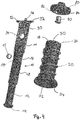
- Fig. 4 shows in a perspective view in the unassembled state the clamping sleeve 30, the spring tensioner 10, the striking element 90, the intermediate element 15, the spring 20, the percussion cap receptacle 80 and the percussion cap 70.
- the striking element 90 can be connected to the spring tensioner 10.
- the Striking element 90 is positioned in the longitudinal slot 16 of the spring tensioner 10 in such a way that the transverse bore 17 and the bore 94 are aligned with one another. This position can be locked by inserting the intermediate element 15, which is designed as a ball here, and inserted into the clamping sleeve 30 so that the striking element 90 is arranged in the sleeve slot 36 and locked in the longitudinal direction.
- the striking element 90 has a flat, substantially rectangular structure.
- the bore 94 is formed approximately in the middle.
- the striking piece 96 extends in the longitudinal direction and two projections 92 are formed in the transverse direction.
- the striking element 90 is preferably a sheet metal part.
Landscapes
- Engineering & Computer Science (AREA)
- General Engineering & Computer Science (AREA)
- Automotive Seat Belt Assembly (AREA)
- Portable Nailing Machines And Staplers (AREA)
Claims (15)
- Unité de tir (1) pour une munition, notamment pour une fusée-signal, comprenant au moins
une douille de serrage (30), un élément de frappe (90) monté mobile dans le sens axial à l'intérieur de la douille de serrage (30), un élément de serrage (20) destiné à serrer l'élément de frappe (90), un organe de traction (2) relié à l'élément de frappe (90), caractérisée en ce que
l'organe de traction (2) est de configuration télescopique. - Unité de tir (1) selon la revendication 1, caractérisée en ce que l'élément de serrage (20) est un ressort.
- Unité de tir (1) selon la revendication 2, caractérisée en ce que l'organe de traction (2) est réalisé en deux parties, l'organe de traction (2) comportant un tendeur à ressort (10) relié à l'élément de frappe (90) et un capuchon (60) disposé de manière télescopique par rapport au tendeur à ressort (10).
- Unité de tir (1) selon la revendication 2 ou 3, caractérisée en ce que le ressort (20), du côté de son pourtour, est monté sur la douille de serrage (30).
- Unité de tir (1) selon l'une des revendications 3 ou 4, caractérisée en ce que le tendeur à ressort (10) possède une fente longitudinale (16), et la douille de serrage (30) possède au moins une fente de douille (36), et l'élément de frappe (90) est un élément plat et possède au moins une partie saillante (92) ou un crochet, la partie saillante (92) ou le crochet s'étendant à travers la fente longitudinale (16) et la fente de douille (36) et se trouvant en prise avec l'élément de serrage (20).
- Unité de tir (1) selon l'une des revendications précédentes, caractérisée en ce que l'unité de tir (1) possède une douille de sécurité (50) reliée à la douille de serrage (30).
- Unité de tir (1) selon l'une des revendications précédentes, caractérisée en ce que la douille de sécurité (50) et le capuchon (60) possèdent une fermeture (52, 62) détachable de manière réversible servant à bloquer le capuchon (60) sur la douille de sécurité (50).
- Unité de tir (1) selon la revendication 7, caractérisée en ce que la fermeture (52, 62) détachable de manière réversible est une fermeture à visser, le capuchon (60) possédant un filet (52) et la douille de sécurité (50) possédant un filet (62), moyennant quoi le capuchon (60) est relié à la douille de sécurité (50) de manière détachable et réversible.
- Unité de tir (1) selon l'une des revendications 3 à 8, caractérisée en ce que le tendeur à ressort (10) possède une zone de guidage (18) pourvue d'un trou transversal (17) et l'élément de frappe (90) possède un trou (94) et un élément intermédiaire (15) est disposé dans le trou transversal (17) et dans le trou (94).
- Unité de tir (1) selon la revendication 9, caractérisée en ce que le trou est disposé espacé par une première portion (18.1) de la tête (11) du tendeur à ressort (10) et l'élément intermédiaire (15) est disposé dans le trou transversal (17) et dans le trou (94) de telle sorte que lors d'une extraction du tendeur à ressort (10) hors de la douille de serrage (30) de la première portion (18.1), l'élément intermédiaire (15) est libéré.
- Unité de tir (1) selon l'une des revendications 3 à 8, caractérisée en ce que le tendeur à ressort (10) possède une zone de guidage (18) pourvue d'une rainure circonférentielle du côté périphérique et un élément intermédiaire (15) est disposé entre la paroi interne (32) de la douille de serrage (30) et la rainure.
- Unité de tir (1) selon la revendication 11, caractérisée en ce que la rainure est disposée espacée par une première portion (18.1) de la tête (11) du tendeur à ressort (10) et l'élément intermédiaire (15) est disposé entre la paroi interne (32) de la douille de serrage (30) et la rainure de telle sorte que lors d'une extraction du tendeur à ressort (10) hors de la douille de serrage (30) de la première portion (18.1), l'élément intermédiaire (15) est libéré.
- Unité de tir (1) selon l'une des revendications 3 à 12, caractérisée en ce que le tendeur à ressort (10) possède un tenon (12) et le capuchon (60) possède au moins un, de préférence deux, trois ou quatre nervures (63) ayant chacune un élément de maintien (64), lesquelles sont configurées de telle sorte que le capuchon (60) peut coulisser le long du tenon (12) du tendeur à ressort (10).
- Unité de tir (1) selon la revendication 13, caractérisée en ce que le tenon (12) possède un fond de tenon (14) qui est façonné de telle sorte que celui-ci forme une butée pour les éléments de maintien (64).
- Unité de tir (1) selon l'une des revendications précédentes, caractérisée en ce qu'un logement d'amorce d'allumage (80) relié à la douille de serrage (30) est disposé au-dessus de la douille de serrage (30).
Applications Claiming Priority (1)
| Application Number | Priority Date | Filing Date | Title |
|---|---|---|---|
| DE102018122223.8A DE102018122223A1 (de) | 2018-09-12 | 2018-09-12 | Abschusseinheit für eine Munition |
Publications (2)
| Publication Number | Publication Date |
|---|---|
| EP3623741A1 EP3623741A1 (fr) | 2020-03-18 |
| EP3623741B1 true EP3623741B1 (fr) | 2021-04-28 |
Family
ID=67734550
Family Applications (1)
| Application Number | Title | Priority Date | Filing Date |
|---|---|---|---|
| EP19193103.9A Active EP3623741B1 (fr) | 2018-09-12 | 2019-08-22 | Unité de tir pour munition |
Country Status (2)
| Country | Link |
|---|---|
| EP (1) | EP3623741B1 (fr) |
| DE (1) | DE102018122223A1 (fr) |
Family Cites Families (12)
| Publication number | Priority date | Publication date | Assignee | Title |
|---|---|---|---|---|
| DE361172C (de) | 1922-10-12 | Julius Loewenberg | An einem Gewehrlauf angebrachte Abschussvorrichtung fuer Leucht- oder Signalmittel oder Gewehrgranaten | |
| US2331198A (en) * | 1941-10-03 | 1943-10-05 | Klang Piao | Hand grenade |
| DE1254509B (de) | 1964-04-23 | 1967-11-16 | Silberhuette Pyrotechnik Veb | Handsignal |
| DE1553893A1 (de) | 1967-05-24 | 1971-07-15 | Nico Pyrotechnik | Signalpatrone |
| US3820462A (en) * | 1973-01-29 | 1974-06-28 | C Jackson | Aerial signal unit |
| US3956843A (en) * | 1975-03-13 | 1976-05-18 | Smith & Wesson Chemical Company, Inc. | Dual range projectile and launching device and disposable launching tube assembly therefor |
| DD288725A7 (de) | 1978-08-24 | 1991-04-11 | Pyrotechnik Silberhuette Gmbh I.G.,De | Abschlussvorrichtung fuer leucht- und signalraketen |
| DE3707062A1 (de) | 1987-01-29 | 1988-08-25 | Comet Pyrotech | Signalmittel, insbesondere signalrakete oder -patrone |
| DE9407053U1 (de) | 1994-04-28 | 1994-07-28 | Comet GmbH Pyrotechnik-Apparatebau, 27574 Bremerhaven | Signalmittel, insbesondere Signalrakete |
| DE102007015248A1 (de) | 2007-03-27 | 2008-10-02 | Chemring Defence Germany Gmbh | Fallschirmrakete, insbesondere Fallschirmsignalrakete und/oder Fallschirmleuchtrakete, und Verfahren zur Herstellung derselben |
| DE102007052728A1 (de) | 2007-10-04 | 2009-04-09 | Chemring Defence Germany Gmbh | Pyrotechnisches Signalmittel |
| JP6023619B2 (ja) * | 2013-03-22 | 2016-11-09 | 細谷火工株式会社 | 衝撃雷管点火装置 |
-
2018
- 2018-09-12 DE DE102018122223.8A patent/DE102018122223A1/de not_active Ceased
-
2019
- 2019-08-22 EP EP19193103.9A patent/EP3623741B1/fr active Active
Non-Patent Citations (1)
| Title |
|---|
| None * |
Also Published As
| Publication number | Publication date |
|---|---|
| EP3623741A1 (fr) | 2020-03-18 |
| DE102018122223A1 (de) | 2020-03-12 |
Similar Documents
| Publication | Publication Date | Title |
|---|---|---|
| DE69703042T2 (de) | Nichtletales geschoss | |
| DE69015046T2 (de) | Zündvorrichtung einer Zündkette für Submunitionskörpern. | |
| DE2303435A1 (de) | Vorrichtung fuer eine patronenkammer in einem patronenbetriebenen werkzeug (schiessapparat) | |
| EP3623741B1 (fr) | Unité de tir pour munition | |
| DE3880930T2 (de) | Armiergeraet mit sicherheitsvorrichtung fuer ein von einem traeger abgeworfenes projektil. | |
| DE1506101A1 (de) | Vorrichtung zur einwandfreien Entfaltung von Fallschirmen | |
| EP0602632A2 (fr) | Fusée à sécurité de bouche et projectile comportant une telle fusée | |
| DE69609255T2 (de) | Vorrichtung zum Zünden einer Treibladung für eine aus einem Trägergeschoss geworfene Submunition | |
| DE19916775C2 (de) | Submunitionsgeschoß | |
| DE641341C (de) | Aufschlagzuender | |
| DE2400947B2 (de) | Sicherungs- und entsicherungsvorrichtung fuer geschosszuender | |
| DE7835715U1 (de) | Bodensprengzuender | |
| EP3396301B1 (fr) | Grenade ainsi que procédé de fonctionnement d'une grenade | |
| EP3076122B1 (fr) | Système de déclenchement d'avalanches | |
| DE2149117A1 (de) | Geschosszuender | |
| AT405978B (de) | Schlagvorrichtung | |
| AT214812B (de) | Mechanischer Aufschlagzünder für Geschosse mit doppelter und mehrfacher Anfeuerung | |
| AT374584B (de) | Sicherungseinrichtung bei einer granate | |
| AT301395B (de) | Aufschlagzünder für Geschosse | |
| DE2105957A1 (de) | Geschoß | |
| EP3457076B1 (fr) | Corps actif à couvercle de freinage | |
| DE502632C (de) | Zuender, insbesondere fuer Handgranaten | |
| DE3344009A1 (de) | Aufschlagzuender fuer bombletts | |
| DE185643C (fr) | ||
| EP3336482B1 (fr) | Méthode et dispositif pour enclencher ou inhiber la sécurité d'un projectile lancé manuellement |
Legal Events
| Date | Code | Title | Description |
|---|---|---|---|
| PUAI | Public reference made under article 153(3) epc to a published international application that has entered the european phase |
Free format text: ORIGINAL CODE: 0009012 |
|
| STAA | Information on the status of an ep patent application or granted ep patent |
Free format text: STATUS: THE APPLICATION HAS BEEN PUBLISHED |
|
| AK | Designated contracting states |
Kind code of ref document: A1 Designated state(s): AL AT BE BG CH CY CZ DE DK EE ES FI FR GB GR HR HU IE IS IT LI LT LU LV MC MK MT NL NO PL PT RO RS SE SI SK SM TR |
|
| AX | Request for extension of the european patent |
Extension state: BA ME |
|
| RIN1 | Information on inventor provided before grant (corrected) |
Inventor name: GNADE, MICHAEL Inventor name: ZIMMERMANN, FRANZISKA Inventor name: WIEHLE, HARTMUT Inventor name: SCHMIDT, ROBERT Inventor name: SENFT, MARTIN |
|
| STAA | Information on the status of an ep patent application or granted ep patent |
Free format text: STATUS: REQUEST FOR EXAMINATION WAS MADE |
|
| 17P | Request for examination filed |
Effective date: 20200814 |
|
| RBV | Designated contracting states (corrected) |
Designated state(s): AL AT BE BG CH CY CZ DE DK EE ES FI FR GB GR HR HU IE IS IT LI LT LU LV MC MK MT NL NO PL PT RO RS SE SI SK SM TR |
|
| GRAP | Despatch of communication of intention to grant a patent |
Free format text: ORIGINAL CODE: EPIDOSNIGR1 |
|
| STAA | Information on the status of an ep patent application or granted ep patent |
Free format text: STATUS: GRANT OF PATENT IS INTENDED |
|
| RIC1 | Information provided on ipc code assigned before grant |
Ipc: F42C 15/20 20060101ALI20201111BHEP Ipc: F41C 3/02 20060101AFI20201111BHEP Ipc: F42C 15/44 20060101ALI20201111BHEP |
|
| INTG | Intention to grant announced |
Effective date: 20201126 |
|
| GRAS | Grant fee paid |
Free format text: ORIGINAL CODE: EPIDOSNIGR3 |
|
| GRAA | (expected) grant |
Free format text: ORIGINAL CODE: 0009210 |
|
| STAA | Information on the status of an ep patent application or granted ep patent |
Free format text: STATUS: THE PATENT HAS BEEN GRANTED |
|
| AK | Designated contracting states |
Kind code of ref document: B1 Designated state(s): AL AT BE BG CH CY CZ DE DK EE ES FI FR GB GR HR HU IE IS IT LI LT LU LV MC MK MT NL NO PL PT RO RS SE SI SK SM TR |
|
| REG | Reference to a national code |
Ref country code: GB Ref legal event code: FG4D Free format text: NOT ENGLISH |
|
| REG | Reference to a national code |
Ref country code: CH Ref legal event code: EP |
|
| REG | Reference to a national code |
Ref country code: DE Ref legal event code: R096 Ref document number: 502019001311 Country of ref document: DE |
|
| REG | Reference to a national code |
Ref country code: AT Ref legal event code: REF Ref document number: 1387536 Country of ref document: AT Kind code of ref document: T Effective date: 20210515 |
|
| REG | Reference to a national code |
Ref country code: IE Ref legal event code: FG4D Free format text: LANGUAGE OF EP DOCUMENT: GERMAN |
|
| REG | Reference to a national code |
Ref country code: NO Ref legal event code: CREP Representative=s name: CHRISTIAN POMMERIN, C/O THUL PATENTANWALTSGESELLSCHAFT Ref country code: NO Ref legal event code: T2 Effective date: 20210428 |
|
| REG | Reference to a national code |
Ref country code: LT Ref legal event code: MG9D |
|
| PG25 | Lapsed in a contracting state [announced via postgrant information from national office to epo] |
Ref country code: BG Free format text: LAPSE BECAUSE OF FAILURE TO SUBMIT A TRANSLATION OF THE DESCRIPTION OR TO PAY THE FEE WITHIN THE PRESCRIBED TIME-LIMIT Effective date: 20210728 Ref country code: NL Free format text: LAPSE BECAUSE OF FAILURE TO SUBMIT A TRANSLATION OF THE DESCRIPTION OR TO PAY THE FEE WITHIN THE PRESCRIBED TIME-LIMIT Effective date: 20210428 Ref country code: HR Free format text: LAPSE BECAUSE OF FAILURE TO SUBMIT A TRANSLATION OF THE DESCRIPTION OR TO PAY THE FEE WITHIN THE PRESCRIBED TIME-LIMIT Effective date: 20210428 Ref country code: LT Free format text: LAPSE BECAUSE OF FAILURE TO SUBMIT A TRANSLATION OF THE DESCRIPTION OR TO PAY THE FEE WITHIN THE PRESCRIBED TIME-LIMIT Effective date: 20210428 Ref country code: FI Free format text: LAPSE BECAUSE OF FAILURE TO SUBMIT A TRANSLATION OF THE DESCRIPTION OR TO PAY THE FEE WITHIN THE PRESCRIBED TIME-LIMIT Effective date: 20210428 |
|
| PG25 | Lapsed in a contracting state [announced via postgrant information from national office to epo] |
Ref country code: PL Free format text: LAPSE BECAUSE OF FAILURE TO SUBMIT A TRANSLATION OF THE DESCRIPTION OR TO PAY THE FEE WITHIN THE PRESCRIBED TIME-LIMIT Effective date: 20210428 Ref country code: LV Free format text: LAPSE BECAUSE OF FAILURE TO SUBMIT A TRANSLATION OF THE DESCRIPTION OR TO PAY THE FEE WITHIN THE PRESCRIBED TIME-LIMIT Effective date: 20210428 Ref country code: PT Free format text: LAPSE BECAUSE OF FAILURE TO SUBMIT A TRANSLATION OF THE DESCRIPTION OR TO PAY THE FEE WITHIN THE PRESCRIBED TIME-LIMIT Effective date: 20210830 Ref country code: SE Free format text: LAPSE BECAUSE OF FAILURE TO SUBMIT A TRANSLATION OF THE DESCRIPTION OR TO PAY THE FEE WITHIN THE PRESCRIBED TIME-LIMIT Effective date: 20210428 Ref country code: RS Free format text: LAPSE BECAUSE OF FAILURE TO SUBMIT A TRANSLATION OF THE DESCRIPTION OR TO PAY THE FEE WITHIN THE PRESCRIBED TIME-LIMIT Effective date: 20210428 Ref country code: GR Free format text: LAPSE BECAUSE OF FAILURE TO SUBMIT A TRANSLATION OF THE DESCRIPTION OR TO PAY THE FEE WITHIN THE PRESCRIBED TIME-LIMIT Effective date: 20210729 Ref country code: IS Free format text: LAPSE BECAUSE OF FAILURE TO SUBMIT A TRANSLATION OF THE DESCRIPTION OR TO PAY THE FEE WITHIN THE PRESCRIBED TIME-LIMIT Effective date: 20210828 |
|
| REG | Reference to a national code |
Ref country code: NL Ref legal event code: MP Effective date: 20210428 |
|
| PG25 | Lapsed in a contracting state [announced via postgrant information from national office to epo] |
Ref country code: SM Free format text: LAPSE BECAUSE OF FAILURE TO SUBMIT A TRANSLATION OF THE DESCRIPTION OR TO PAY THE FEE WITHIN THE PRESCRIBED TIME-LIMIT Effective date: 20210428 Ref country code: RO Free format text: LAPSE BECAUSE OF FAILURE TO SUBMIT A TRANSLATION OF THE DESCRIPTION OR TO PAY THE FEE WITHIN THE PRESCRIBED TIME-LIMIT Effective date: 20210428 Ref country code: CZ Free format text: LAPSE BECAUSE OF FAILURE TO SUBMIT A TRANSLATION OF THE DESCRIPTION OR TO PAY THE FEE WITHIN THE PRESCRIBED TIME-LIMIT Effective date: 20210428 Ref country code: DK Free format text: LAPSE BECAUSE OF FAILURE TO SUBMIT A TRANSLATION OF THE DESCRIPTION OR TO PAY THE FEE WITHIN THE PRESCRIBED TIME-LIMIT Effective date: 20210428 Ref country code: SK Free format text: LAPSE BECAUSE OF FAILURE TO SUBMIT A TRANSLATION OF THE DESCRIPTION OR TO PAY THE FEE WITHIN THE PRESCRIBED TIME-LIMIT Effective date: 20210428 Ref country code: ES Free format text: LAPSE BECAUSE OF FAILURE TO SUBMIT A TRANSLATION OF THE DESCRIPTION OR TO PAY THE FEE WITHIN THE PRESCRIBED TIME-LIMIT Effective date: 20210428 Ref country code: EE Free format text: LAPSE BECAUSE OF FAILURE TO SUBMIT A TRANSLATION OF THE DESCRIPTION OR TO PAY THE FEE WITHIN THE PRESCRIBED TIME-LIMIT Effective date: 20210428 |
|
| REG | Reference to a national code |
Ref country code: DE Ref legal event code: R097 Ref document number: 502019001311 Country of ref document: DE |
|
| REG | Reference to a national code |
Ref legal event code: R082 Ref document number: 502019001311 Ref country code: DE Ref legal event code: R082 Ref document number: 502019001311 Country of ref document: DE Representative=s name: DREISS PATENTANWAELTE PARTG MBB, DE |
|
| REG | Reference to a national code |
Ref country code: DE Ref legal event code: R082 Ref document number: 502019001311 Country of ref document: DE Representative=s name: DREISS PATENTANWAELTE PARTG MBB, DE |
|
| PLBE | No opposition filed within time limit |
Free format text: ORIGINAL CODE: 0009261 |
|
| STAA | Information on the status of an ep patent application or granted ep patent |
Free format text: STATUS: NO OPPOSITION FILED WITHIN TIME LIMIT |
|
| RAP4 | Party data changed (patent owner data changed or rights of a patent transferred) |
Owner name: RHEINMETALL WAFFE MUNITION GMBH |
|
| PG25 | Lapsed in a contracting state [announced via postgrant information from national office to epo] |
Ref country code: MC Free format text: LAPSE BECAUSE OF FAILURE TO SUBMIT A TRANSLATION OF THE DESCRIPTION OR TO PAY THE FEE WITHIN THE PRESCRIBED TIME-LIMIT Effective date: 20210428 |
|
| 26N | No opposition filed |
Effective date: 20220131 |
|
| REG | Reference to a national code |
Ref country code: BE Ref legal event code: MM Effective date: 20210831 |
|
| PG25 | Lapsed in a contracting state [announced via postgrant information from national office to epo] |
Ref country code: IS Free format text: LAPSE BECAUSE OF FAILURE TO SUBMIT A TRANSLATION OF THE DESCRIPTION OR TO PAY THE FEE WITHIN THE PRESCRIBED TIME-LIMIT Effective date: 20210828 Ref country code: LU Free format text: LAPSE BECAUSE OF NON-PAYMENT OF DUE FEES Effective date: 20210822 Ref country code: AL Free format text: LAPSE BECAUSE OF FAILURE TO SUBMIT A TRANSLATION OF THE DESCRIPTION OR TO PAY THE FEE WITHIN THE PRESCRIBED TIME-LIMIT Effective date: 20210428 |
|
| PG25 | Lapsed in a contracting state [announced via postgrant information from national office to epo] |
Ref country code: IT Free format text: LAPSE BECAUSE OF FAILURE TO SUBMIT A TRANSLATION OF THE DESCRIPTION OR TO PAY THE FEE WITHIN THE PRESCRIBED TIME-LIMIT Effective date: 20210428 Ref country code: IE Free format text: LAPSE BECAUSE OF NON-PAYMENT OF DUE FEES Effective date: 20210822 Ref country code: BE Free format text: LAPSE BECAUSE OF NON-PAYMENT OF DUE FEES Effective date: 20210831 |
|
| REG | Reference to a national code |
Ref country code: CH Ref legal event code: PL |
|
| PG25 | Lapsed in a contracting state [announced via postgrant information from national office to epo] |
Ref country code: LI Free format text: LAPSE BECAUSE OF NON-PAYMENT OF DUE FEES Effective date: 20220831 Ref country code: CH Free format text: LAPSE BECAUSE OF NON-PAYMENT OF DUE FEES Effective date: 20220831 |
|
| PG25 | Lapsed in a contracting state [announced via postgrant information from national office to epo] |
Ref country code: CY Free format text: LAPSE BECAUSE OF FAILURE TO SUBMIT A TRANSLATION OF THE DESCRIPTION OR TO PAY THE FEE WITHIN THE PRESCRIBED TIME-LIMIT Effective date: 20210428 |
|
| PG25 | Lapsed in a contracting state [announced via postgrant information from national office to epo] |
Ref country code: HU Free format text: LAPSE BECAUSE OF FAILURE TO SUBMIT A TRANSLATION OF THE DESCRIPTION OR TO PAY THE FEE WITHIN THE PRESCRIBED TIME-LIMIT; INVALID AB INITIO Effective date: 20190822 |
|
| PG25 | Lapsed in a contracting state [announced via postgrant information from national office to epo] |
Ref country code: MK Free format text: LAPSE BECAUSE OF FAILURE TO SUBMIT A TRANSLATION OF THE DESCRIPTION OR TO PAY THE FEE WITHIN THE PRESCRIBED TIME-LIMIT Effective date: 20210428 |
|
| PG25 | Lapsed in a contracting state [announced via postgrant information from national office to epo] |
Ref country code: TR Free format text: LAPSE BECAUSE OF FAILURE TO SUBMIT A TRANSLATION OF THE DESCRIPTION OR TO PAY THE FEE WITHIN THE PRESCRIBED TIME-LIMIT Effective date: 20210428 |
|
| PG25 | Lapsed in a contracting state [announced via postgrant information from national office to epo] |
Ref country code: MT Free format text: LAPSE BECAUSE OF FAILURE TO SUBMIT A TRANSLATION OF THE DESCRIPTION OR TO PAY THE FEE WITHIN THE PRESCRIBED TIME-LIMIT Effective date: 20210428 |
|
| PGFP | Annual fee paid to national office [announced via postgrant information from national office to epo] |
Ref country code: DE Payment date: 20250820 Year of fee payment: 7 |
|
| PGFP | Annual fee paid to national office [announced via postgrant information from national office to epo] |
Ref country code: NO Payment date: 20250826 Year of fee payment: 7 |
|
| REG | Reference to a national code |
Ref country code: AT Ref legal event code: MM01 Ref document number: 1387536 Country of ref document: AT Kind code of ref document: T Effective date: 20240822 |
|
| PGFP | Annual fee paid to national office [announced via postgrant information from national office to epo] |
Ref country code: GB Payment date: 20250820 Year of fee payment: 7 |
|
| PG25 | Lapsed in a contracting state [announced via postgrant information from national office to epo] |
Ref country code: AT Free format text: LAPSE BECAUSE OF NON-PAYMENT OF DUE FEES Effective date: 20240822 |
|
| PGFP | Annual fee paid to national office [announced via postgrant information from national office to epo] |
Ref country code: FR Payment date: 20250828 Year of fee payment: 7 |
|
| PGFP | Annual fee paid to national office [announced via postgrant information from national office to epo] |
Ref country code: AT Payment date: 20260410 Year of fee payment: 5 |