EP3623748B1 - Système pour déterminer l'allongement longitudinal d'une courroie - Google Patents
Système pour déterminer l'allongement longitudinal d'une courroie Download PDFInfo
- Publication number
- EP3623748B1 EP3623748B1 EP19190163.6A EP19190163A EP3623748B1 EP 3623748 B1 EP3623748 B1 EP 3623748B1 EP 19190163 A EP19190163 A EP 19190163A EP 3623748 B1 EP3623748 B1 EP 3623748B1
- Authority
- EP
- European Patent Office
- Prior art keywords
- belt
- marking part
- transmitter
- marking
- alternating field
- Prior art date
- Legal status (The legal status is an assumption and is not a legal conclusion. Google has not performed a legal analysis and makes no representation as to the accuracy of the status listed.)
- Active
Links
Images



Classifications
-
- G—PHYSICS
- G01—MEASURING; TESTING
- G01B—MEASURING LENGTH, THICKNESS OR SIMILAR LINEAR DIMENSIONS; MEASURING ANGLES; MEASURING AREAS; MEASURING IRREGULARITIES OF SURFACES OR CONTOURS
- G01B7/00—Measuring arrangements characterised by the use of electric or magnetic techniques
- G01B7/16—Measuring arrangements characterised by the use of electric or magnetic techniques for measuring the deformation in a solid, e.g. by resistance strain gauge
- G01B7/24—Measuring arrangements characterised by the use of electric or magnetic techniques for measuring the deformation in a solid, e.g. by resistance strain gauge using change in magnetic properties
-
- B—PERFORMING OPERATIONS; TRANSPORTING
- B65—CONVEYING; PACKING; STORING; HANDLING THIN OR FILAMENTARY MATERIAL
- B65G—TRANSPORT OR STORAGE DEVICES, e.g. CONVEYORS FOR LOADING OR TIPPING, SHOP CONVEYOR SYSTEMS OR PNEUMATIC TUBE CONVEYORS
- B65G43/00—Control devices, e.g. for safety, warning or fault-correcting
- B65G43/02—Control devices, e.g. for safety, warning or fault-correcting detecting dangerous physical condition of load carriers, e.g. for interrupting the drive in the event of overheating
-
- F—MECHANICAL ENGINEERING; LIGHTING; HEATING; WEAPONS; BLASTING
- F16—ENGINEERING ELEMENTS AND UNITS; GENERAL MEASURES FOR PRODUCING AND MAINTAINING EFFECTIVE FUNCTIONING OF MACHINES OR INSTALLATIONS; THERMAL INSULATION IN GENERAL
- F16G—BELTS, CABLES, OR ROPES, PREDOMINANTLY USED FOR DRIVING PURPOSES; CHAINS; FITTINGS PREDOMINANTLY USED THEREFOR
- F16G5/00—V-belts, i.e. belts of tapered cross-section
- F16G5/04—V-belts, i.e. belts of tapered cross-section made of rubber
- F16G5/06—V-belts, i.e. belts of tapered cross-section made of rubber with reinforcement bonded by the rubber
- F16G5/08—V-belts, i.e. belts of tapered cross-section made of rubber with reinforcement bonded by the rubber with textile reinforcement
-
- F—MECHANICAL ENGINEERING; LIGHTING; HEATING; WEAPONS; BLASTING
- F16—ENGINEERING ELEMENTS AND UNITS; GENERAL MEASURES FOR PRODUCING AND MAINTAINING EFFECTIVE FUNCTIONING OF MACHINES OR INSTALLATIONS; THERMAL INSULATION IN GENERAL
- F16G—BELTS, CABLES, OR ROPES, PREDOMINANTLY USED FOR DRIVING PURPOSES; CHAINS; FITTINGS PREDOMINANTLY USED THEREFOR
- F16G5/00—V-belts, i.e. belts of tapered cross-section
- F16G5/04—V-belts, i.e. belts of tapered cross-section made of rubber
- F16G5/06—V-belts, i.e. belts of tapered cross-section made of rubber with reinforcement bonded by the rubber
- F16G5/10—V-belts, i.e. belts of tapered cross-section made of rubber with reinforcement bonded by the rubber with metal reinforcement
-
- F—MECHANICAL ENGINEERING; LIGHTING; HEATING; WEAPONS; BLASTING
- F16—ENGINEERING ELEMENTS AND UNITS; GENERAL MEASURES FOR PRODUCING AND MAINTAINING EFFECTIVE FUNCTIONING OF MACHINES OR INSTALLATIONS; THERMAL INSULATION IN GENERAL
- F16G—BELTS, CABLES, OR ROPES, PREDOMINANTLY USED FOR DRIVING PURPOSES; CHAINS; FITTINGS PREDOMINANTLY USED THEREFOR
- F16G5/00—V-belts, i.e. belts of tapered cross-section
- F16G5/12—V-belts, i.e. belts of tapered cross-section made of plastics
- F16G5/14—V-belts, i.e. belts of tapered cross-section made of plastics with reinforcement bonded by the plastic material
-
- G—PHYSICS
- G01—MEASURING; TESTING
- G01L—MEASURING FORCE, STRESS, TORQUE, WORK, MECHANICAL POWER, MECHANICAL EFFICIENCY, OR FLUID PRESSURE
- G01L1/00—Measuring force or stress, in general
- G01L1/12—Measuring force or stress, in general by measuring variations in the magnetic properties of materials resulting from the application of stress
- G01L1/122—Measuring force or stress, in general by measuring variations in the magnetic properties of materials resulting from the application of stress by using permanent magnets
-
- G—PHYSICS
- G01—MEASURING; TESTING
- G01M—TESTING STATIC OR DYNAMIC BALANCE OF MACHINES OR STRUCTURES; TESTING OF STRUCTURES OR APPARATUS, NOT OTHERWISE PROVIDED FOR
- G01M13/00—Testing of machine parts
- G01M13/02—Gearings; Transmission mechanisms
- G01M13/023—Power-transmitting endless elements, e.g. belts or chains
-
- G—PHYSICS
- G01—MEASURING; TESTING
- G01M—TESTING STATIC OR DYNAMIC BALANCE OF MACHINES OR STRUCTURES; TESTING OF STRUCTURES OR APPARATUS, NOT OTHERWISE PROVIDED FOR
- G01M5/00—Investigating the elasticity of structures, e.g. deflection of bridges or air-craft wings
- G01M5/0041—Investigating the elasticity of structures, e.g. deflection of bridges or air-craft wings by determining deflection or stress
- G01M5/005—Investigating the elasticity of structures, e.g. deflection of bridges or air-craft wings by determining deflection or stress by means of external apparatus, e.g. test benches or portable test systems
- G01M5/0058—Investigating the elasticity of structures, e.g. deflection of bridges or air-craft wings by determining deflection or stress by means of external apparatus, e.g. test benches or portable test systems of elongated objects, e.g. pipes, masts, towers or railways
-
- B—PERFORMING OPERATIONS; TRANSPORTING
- B65—CONVEYING; PACKING; STORING; HANDLING THIN OR FILAMENTARY MATERIAL
- B65G—TRANSPORT OR STORAGE DEVICES, e.g. CONVEYORS FOR LOADING OR TIPPING, SHOP CONVEYOR SYSTEMS OR PNEUMATIC TUBE CONVEYORS
- B65G15/00—Conveyors having endless load-conveying surfaces, i.e. belts and like continuous members, to which tractive effort is transmitted by means other than endless driving elements of similar configuration
- B65G15/30—Belts or like endless load-carriers
-
- B—PERFORMING OPERATIONS; TRANSPORTING
- B65—CONVEYING; PACKING; STORING; HANDLING THIN OR FILAMENTARY MATERIAL
- B65G—TRANSPORT OR STORAGE DEVICES, e.g. CONVEYORS FOR LOADING OR TIPPING, SHOP CONVEYOR SYSTEMS OR PNEUMATIC TUBE CONVEYORS
- B65G2203/00—Indexing code relating to control or detection of the articles or the load carriers during conveying
- B65G2203/02—Control or detection
- B65G2203/0266—Control or detection relating to the load carrier(s)
- B65G2203/0275—Damage on the load carrier
-
- B—PERFORMING OPERATIONS; TRANSPORTING
- B65—CONVEYING; PACKING; STORING; HANDLING THIN OR FILAMENTARY MATERIAL
- B65G—TRANSPORT OR STORAGE DEVICES, e.g. CONVEYORS FOR LOADING OR TIPPING, SHOP CONVEYOR SYSTEMS OR PNEUMATIC TUBE CONVEYORS
- B65G2203/00—Indexing code relating to control or detection of the articles or the load carriers during conveying
- B65G2203/04—Detection means
- B65G2203/042—Sensors
- B65G2203/043—Magnetic
-
- G—PHYSICS
- G01—MEASURING; TESTING
- G01B—MEASURING LENGTH, THICKNESS OR SIMILAR LINEAR DIMENSIONS; MEASURING ANGLES; MEASURING AREAS; MEASURING IRREGULARITIES OF SURFACES OR CONTOURS
- G01B7/00—Measuring arrangements characterised by the use of electric or magnetic techniques
- G01B7/02—Measuring arrangements characterised by the use of electric or magnetic techniques for measuring length, width or thickness
- G01B7/04—Measuring arrangements characterised by the use of electric or magnetic techniques for measuring length, width or thickness specially adapted for measuring length or width of objects while moving
- G01B7/042—Measuring arrangements characterised by the use of electric or magnetic techniques for measuring length, width or thickness specially adapted for measuring length or width of objects while moving for measuring length
- G01B7/046—Measuring arrangements characterised by the use of electric or magnetic techniques for measuring length, width or thickness specially adapted for measuring length or width of objects while moving for measuring length using magnetic means
Definitions
- the invention relates to a system for determining the longitudinal elongation of a belt.
- a system that has a belt and a drive device for the belt is basically known from the prior art.
- the drive device has several, for example two, pulleys.
- the belt is designed to run annularly in a circumferential direction and at least partially wraps around the pulleys.
- the belt can be driven in the circumferential direction by the drive device.
- a belt is preferably a drive belt for transmitting tensile forces.
- a belt is often exposed to pretension, useful forces, centrifugal forces and/or bends.
- the service life of a belt is at least partly determined by the stretch of the belt, in particular the stretch in the circumferential direction.
- the rate of rotation at which the belt moves and/or the power required to drive the belt can indicate the load on the belt.
- this load can only be used to give a rough estimate of the actual local stretching of the belt. An exact determination based on the aforementioned load is not possible.
- Strain gauges are known from the prior art. However, the use of a strain gauge requires an electrical measuring circuit that is to be coupled to the strain gauge in order to evaluate a strain detected by the strain gauge or to provide a corresponding evaluation signal. In order to use a strain gauge for a belt, you also need one Attachment of the aforementioned evaluation circuit to the belt. In particular, if the belt is exposed to a high temperature during use, which is influenced, for example, by friction of the belt on a deflection pulley and/or by a high ambient temperature, a robust evaluation circuit can only be produced with very high technical effort and corresponding costs High temperatures ensure reliable measurement of the strain using the strain gauge.
- the US 5,291,131 A considers the expansion of a moving endless body such as B. a chain, a belt, a conveyor or the like, which is continuously measured by using two indices, e.g. B. pins or tongues, on the endless body and two sensors, e.g. B. magnetic or optical sensors, can be attached along the orbit of the endless body.
- the sensors are connected to a computing circuit that determines the strain from the data provided by the sensors.
- the JP 2018-047973 A relates to the provision of a device for measuring the elongation of a conveyor belt, which is capable of correctly measuring the elongation of a conveyor belt in a circumferential direction even when the conveyor belt meanders.
- a device for measuring the elongation of a conveyor belt which is capable of correctly measuring the elongation of a conveyor belt in a circumferential direction even when the conveyor belt meanders.
- two magnetic elements which are arranged at a distance in a belt circumferential direction of a conveyor belt
- a magnetic sensor which is arranged opposite an outer peripheral surface of the conveyor belt and serves to detect a magnetic field that the two magnetic elements generate
- a calculation part for calculating the elongation of the conveyor belt Conveyor belt in the belt circumferential direction based on an output signal from the magnetic sensor.
- the calculation part calculates a ratio between the length of the magnetic elements in the tape running direction, which is calculated based on the output signal of the magnetic sensor, and the length of the magnetic elements in the tape circumferential direction, which is actually measured in advance, and corrects a distance in the tape running direction therebetween the two magnetic elements, which is calculated based on the output signal of the magnetic sensor using the ratio.
- the CN 104692078 B describes a method for monitoring the running condition of a conveyor belt, comprising: attaching a plurality of detection elements Signal receiving and transmitting functions within or on the surface of the conveyor belt, and each sensing element stores identification information to identify its identity information.
- a reading device is also provided, which is arranged on one side of the conveyor belt. In the step of parameter acquisition, when the conveyor belt is running, the reader reads the identification information of the detection element, records the detection time, and detects the identification between the reader and the detection element.
- the DE 10 2013 111 191 A1 describes a method for contactless monitoring of a conveyor belt for damage, the conveyor belt having a plurality of electrically conductive inserts that extend at least partially in the transverse direction, the method with the steps: sending a first electromagnetic signal to the conveyor belt, and in a first state at least one electrically conductive insert, reflecting the first electromagnetic signal through the at least one electrically conductive insert as a second electromagnetic signal and receiving the second electromagnetic signal from the conveyor belt, and in a second state of the at least one electrically conductive insert, not receiving the second electromagnetic Signal from the conveyor belt.
- the DE 199 02 759 A1 describes a monitoring device consisting of four reference marks, two addresses for identifying a measuring point and four sensor heads.
- the sensor heads are arranged above the supporting side of the conveyor belt.
- the conveyor belt typically consists of a rubber or rubber-like material with embedded reinforcing elements.
- a measuring device is provided to record the belt temperature and the ambient temperature.
- the DE 10 2010 002 551 A1 describes a belt for transmitting a drive movement with a belt body made of an elastic material and with a carcass which extends in the longitudinal direction of the belt and is at least partially surrounded by the belt body in order to increase the strength of the belt body in the longitudinal direction of the belt, a data memory being arranged in the belt body for storing data, whereby as data at least one belt-identifying information in the Data memory is stored, wherein the drive movement can be stopped and / or released depending on the belt-identifying information.
- the DE 10 2011 051 923 A1 describes a device for continuous and non-destructive monitoring of a conveyor system with the following components: an endlessly closed conveyor belt with a load-side cover plate and a running-side cover plate, each made of a polymeric material with elastic properties and with an embedded tension member; Drums, support rollers and support frames, the aforementioned components in conjunction with the conveyor belt forming a material-conveying upper run with a feed point and delivery point for the conveyed material and a material-conveying or material-free lower run; a conductor loop package with endless closed conductor loops embedded in the conveyor belt; and an electronic slot protection system for contactless detection of damage to the conveyor belt, the slot protection system being an electrical device system that includes at least one interrogation station and at least one slot monitoring station and is connected to a central control that controls the entire conveyor system.
- the device is equipped with sequential conductor loops and a sequential slot protection system as part of a conductor loop package, with the relevant functional logic being described in detail.
- the invention is therefore based on the object of providing a system with which reliable and robust detection of an elongation of a belt - even during operation - can be ensured.
- a system for determining the longitudinal elongation of a belt.
- the system has a belt, a drive device, a transmitter and an evaluation unit.
- the drive device has several pulleys.
- the evaluation unit can be combined with the transmitter.
- the belt has a base material, a reinforcement, a first ferromagnetic marking part and a second ferromagnetic marking part.
- the base material can be at least partially formed, for example, from rubber material or polyurethane material.
- the base material is made of rubber material.
- the belt is in a circumferential direction of the Belt is designed in a ring-shaped circumferential manner. In addition, the belt wraps at least partially around the pulleys.
- the belt can be driven in the circumferential direction from the drive direction.
- the strength member of the belt is designed as a continuous cord that is wound helically in the circumferential direction and is embedded in the base material of the belt.
- the first marking part and the second marking part are each embedded in the base material and/or attached to the base material.
- the transmitter of the system is designed to generate a first, alternating electromagnetic field, which is referred to as the alternating reference field.
- the first ferromagnetic marking part is designed to change the alternating reference field into a second, alternating electromagnetic field when the alternating reference field acts on the first ferromagnetic marking part.
- the second alternating electromagnetic field is referred to as the first alternating reaction field.
- the second ferromagnetic marking part is designed to change the alternating reference field into a third, alternating electromagnetic field when the alternating reference field acts on the second ferromagnetic marking part.
- the third, alternating electromagnetic field is referred to as the second alternating reaction field.
- the second marking part is arranged at a predetermined reference distance in the circumferential direction behind the first marking part, at least in an unloaded state of the belt.
- the transmitter is arranged without contact with the belt in such a way that the first marking part and the second marking part can be guided past the transmitter one after the other by means of the belt and can be passed through the alternating reference field, which results in the alternating reference field acting one after the other on the first marking part and the second marking part .
- the transmitter is also designed to detect the first alternating reaction field and an associated first detection time when the first marking part is moved past the transmitter.
- the transmitter is designed to detect the second alternating reaction field and the associated second detection time when the second marking part is guided past the transmitter.
- the system and in particular the associated transmitter and/or the associated evaluation unit, is configured to determine a belt speed of the belt in the circumferential direction based on the first alternating reaction field and/or the second alternating reaction field.
- the evaluation unit is configured to determine a longitudinal elongation of the belt based on the To determine the reference distance, the belt speed, the first detection time and the second detection time.
- the first and second marking parts are designed to be at least indirectly connected to one another by means of connecting webs, so that the predetermined reference distance can be reliably ensured in the unloaded state of the belt between the two marking parts in the circumferential direction.
- the system offers the advantage that longitudinal stretching of the belt can be determined using the transmitter and the evaluation unit.
- the transmitter can also be referred to and/or designed as a transmitter unit.
- the system's belt is particularly robust against high temperatures and/or other mechanical, external influences.
- an alternating reference field can be generated through which the belt, driven by the drive device, can be moved, so that the first marking part and the second marking part of the belt are moved one after the other through the alternating reference field.
- Each of the two marking parts can be designed for coupling into the alternating reference field. This makes it possible for the alternating reference field to be changed into the first alternating reaction field when the first marking part is moved through the alternating reference field and thereby acts on the alternating reference field.
- the second marking part that the alternating reference field changes into the second alternating reaction field when the second marking part is guided through the alternating reference field and thereby acts on the alternating reference field.
- the reference alternating field, the first alternating reaction field and the second alternating reaction field do not exist at the same time. Rather, only one of the aforementioned alternating fields can exist at any given time.
- a first detection time is recorded by the transmitter when the first alternating reaction field is detected by the transmitter. This occurs when the first marking part is guided past the transmitter, which is designed to generate the alternating reference field. However, by passing the first marking part, the first marking part is coupled into the alternating reference field, which leads to a change in the alternating reference field into the first alternating reaction field. This change occurs at the first detection time detected by the transmitter.
- the second marking part or the second detection time At least in the unloaded state of the belt, the second marking part is at the predetermined reference distance arranged in the circumferential direction behind the first marking part. If the belt is driven in the circumferential direction by means of the drive device, the first marking part first moves through the alternating reference field and then the second marking part. When the second marking part is guided past the transmitter, the second marking part is coupled into the alternating reference field, which leads to the change of the alternating reference field into the second alternating reaction field.
- the transmitter is designed to detect this second alternating reaction field and the associated second detection time.
- first and second marking parts In principle, it is possible for the first and second marking parts to have the same design. However, the two marking parts can also be designed differently.
- the system is configured to determine the belt speed of the belt in the circumferential direction based on the first alternating reaction field or the second alternating reaction field.
- the transmitter which is designed to determine the belt speed of the belt in the circumferential direction based on the first alternating reaction field and/or the second alternating reaction field.
- the transmitter can be designed as a magnetoresistive transmitter and/or include the function of a magnetoresistive sensor.
- the second marking part is arranged at a predetermined reference distance in the circumferential direction behind the first marking part.
- the belt is not in the unloaded state, but rather, for example, in a loaded state in which a tensile force acts on the belt, in particular on a tension strand of the belt, the distance between the second marking part and the first marking part increases in the circumferential direction .
- the distance between the first detection time and the second detection time increases at the same belt speed when the belt changes from the unloaded state to the previously explained loaded state.
- the elongation of the belt in the circumferential direction which is also referred to as the longitudinal elongation of the belt, can be deduced from the first and second detection times, the belt speed and the reference distance.
- the evaluation unit is configured to determine a longitudinal elongation of the belt based on the reference distance, the belt speed, the first detection time and the second detection time.
- the longitudinal elongation of the belt To determine the longitudinal elongation of the belt, no mechanical intervention in the belt is required during operation of the belt. Rather, the longitudinal elongation of the belt can be recorded without contact during operation of the belt.
- the first marking part and the second marking part which are each embedded in the base material of the belt, offer the advantage that the determination of the longitudinal elongation of the belt is possible in a particularly precise and/or robust manner against temperature influences, even at a high temperature of the belt. Because the first and second marking parts are embedded in the base material, the determination of the longitudinal elongation of the belt is also particularly robust against possible mechanical influences that can act on the belt.
- the elongation is preferably a relative elongation.
- the longitudinal stretch of the belt can therefore be a relative stretch of the belt in the longitudinal direction.
- each of the two ferromagnetic marking parts causes a change in the alternating reference field.
- the change does not necessarily take place uniformly over the entire frequency band of the reference alternating field. Rather, it is possible for each of the two ferromagnetic marking parts to be designed to change a predetermined frequency range, so that the change in the alternating reference field caused thereby is characteristic and/or representative of the respective marking part.
- Each marking part therefore preferably causes an associated change in the alternating reference field, so that a corresponding alternating reaction field, namely the first alternating reaction field or the second alternating reaction field, arises from the interaction of the alternating reference field with the respective marking part.
- each capture time may also be referred to as a capture time.
- Each detection time preferably represents the time of the maximum change in the respective reference alternating field respective marking part.
- a period of time can be determined from the two recording times, and the relative elongation of the belt can be deduced from the period, the belt speed and the reference distance.
- the evaluation unit is preferably configured accordingly.
- the transmitter and the evaluation unit can be formed by a common unit, which can also be referred to as a transmitter evaluation unit.
- An advantageous embodiment of the system is characterized in that the evaluation unit is configured to determine a remaining service life of the belt based on a history of determined longitudinal stretches of the belt.
- the evaluation unit can thus be designed to determine several longitudinal strains one after the other. The determination can take place at fixed intervals. However, it is also possible for the determination to be triggered by the detection of the second reaction alternating field.
- the recorded longitudinal strains can be stored by the evaluation unit. Based on these determined longitudinal strains, the evaluation unit can therefore be configured to determine the remaining service life of the belt. A correspondingly determined remaining service life can be used to plan maintenance intervals and/or the replacement of the belt in advance.
- a further advantageous embodiment of the system is characterized in that the first detection time represents a time of a maximum change in the alternating reference field by the first marking part, and in that the second detection time represents a time of a maximum change in the alternating reference field by the second marking part. If the first or second marking part is moved through the alternating reference field, the greatest change in the alternating reference field often occurs, for example, when the respective marking part is arranged centrally in the alternating reference field. The movement of the respective marking part to the central arrangement or the movement out of this central arrangement leads to a decrease in the change in the reference alternating field.
- the first detection time represents the time of the maximum change in the first alternating reference field by the first marking part.
- the second Detection time which is represented by the time of the maximum change in the reference alternating field by the second marking part.
- a further advantageous embodiment of the system is characterized in that the transmitter, in particular as part of a transmitter evaluation unit, is arranged contact-free on a strand of the belt.
- the strand can be formed by a tension strand of the belt.
- a further advantageous embodiment of the system is characterized in that the transmitter, in particular as part of the transmitter evaluation unit, is arranged at a distance of between 1 mm and 50 cm from the strand of the belt. This is preferably a tension strand of the belt.
- the predetermined distance can ensure that the transmitter has no direct mechanical contact with the belt. This means that the longitudinal stretching of the belt can be carried out during operation without any negative mechanical influence on the belt. Because the predetermined distance is between 1 mm and 50 cm, it can also be ensured that electromagnetic interference only has a negligible influence on the detection of the first and/or second alternating reaction field. This makes it possible to detect the first or second alternating reaction field in a very robust manner to disturbance variables.
- a further advantageous embodiment of the system is characterized in that the reference distance is smaller than the smallest span length of the belt.
- the second marking part is arranged behind the first marking part at the reference distance in the circumferential direction of the belt when the belt is in an unloaded state.
- the smallest strand length of the belt preferably refers to the smallest of the at least one strand length of the at least one tension strand of the belt.
- the system it is also possible for the system to be designed in such a way that the reference distance is smaller than one is the strand length of any tension strand of the belt. The reference distance is therefore determined in such a way that during rotation of the belt there is at least one point in time at which both the first marking part and the second marking part are arranged in the same tension strand.
- the distance between the two marking parts can be greater than the reference distance. However, this is usually only the case in a single-digit percentage range. Therefore, it can also be assumed that even in the event of a tensile load, the requirement is met that both marking parts are arranged simultaneously in the same tension strand at at least one point in time when the belt is rotating.
- the two marking parts can be moved one after the other through the reference alternating field, which enables the previously explained determination of the longitudinal elongation of the belt.
- the determined longitudinal elongation of the belt represents the longitudinal elongation of the belt in the tension strand. This is particularly interesting and/or representative.
- the tension strand is often where the greatest load and/or the greatest tensile load on the belt occurs.
- This load or the longitudinal stretch of the belt recorded there can therefore be advantageously used for further evaluation and/or for further predictions about the condition of the belt.
- the stretch state of a slack strand of the belt is of interest.
- the reference distance between the marking arrows is smaller than a span length of an empty span. The system can then be used to determine, for example, the longitudinal elongation of the slack strand, in particular due to a pretension of the belt. This can also be of interest in practice.
- a further advantageous embodiment of the system is characterized in that the reference distance is a maximum of 90%, a maximum of 80%, a maximum of 70%, a maximum of 60% or a maximum of 50% of a span length of the belt.
- This is preferably the shortest strand length and/or the strand length of the tension strand, in particular the shortest tension strand.
- each marking part is designed to be passive, in particular purely passive.
- Each of the two marking parts can therefore be designed as a passive, ferromagnetic marking part.
- the passive design of the respective marking part is sufficient to change the reference alternating field, since the ferromagnetic material of the respective marking part can cause an induction-based change in the alternating field due to the arrangement in the reference alternating field.
- Neither of the two marking parts is therefore coupled to other electronic components. Rather, it is preferably provided that each of the two marking parts is completely embedded in the base material of the belt, so that each of the two marking parts is completely covered by the base material.
- each of the two marking parts is arranged without contact with the strength member of the belt and/or other possible components of the belt.
- This offers the advantage that no friction effect occurs between the strength member of the belt and one of the two marking parts, even when the belt is under greater load.
- This can effectively ensure that no friction and/or wear of the belt is caused by embedding the marking parts in the base material of the belt.
- the belt is therefore particularly robust.
- each marking part is designed as a rod-shaped marking part or as a film-shaped marking part.
- each marking part extends with its greatest extent transversely to the circumferential direction of the belt.
- the longitudinal axis of each rod-shaped marking part can be arranged transversely to the circumferential direction.
- the film-shaped marking part there is also the possibility that the film has a greatest extent in a direction that is arranged transversely to the circumferential direction.
- each marking part extends from one side wall to the opposite side wall of the belt. Each sidewall may be located on a corresponding side flank of the belt.
- each marking part can extend at least substantially completely in the transverse direction from one side wall to the opposite side wall.
- an extension length of each Marking part is between 95% and 70% of the distance between the two side walls. This can effectively ensure that each marking part is spaced at least a small distance inwards from the respective outside. As a result, electromagnetic influence on the marking parts can be prevented and/or insulation of the marking parts can be ensured particularly effectively by the base material.
- Each marking part can, for example, have a diameter and/or a thickness of 5 ⁇ m to 0.5 mm. This has a negligible influence on the stiffness of the belt.
- each marking part is prefabricated.
- a correspondingly prefabricated marking part can therefore be embedded particularly easily into the base material of the belt when producing the belt.
- each marking part is designed as a printed marking part.
- the marking part can be formed by a printed, ferromagnetic metal marking part.
- the marking part it is also possible for the marking part to be formed by a material mixture of ferromagnetic material and another printable material.
- each marking part can be printed at a designated location in order to then completely embed the respective marking part into the rubber material. This makes it possible to embed the respective marking part in the rubber material in a particularly simple and at the same time precise manner.
- each marking part is formed in one piece. This makes it possible for each marking part to be completely embedded in the belt, surrounded by the base material. Due to the base material, each marking part can thus be arranged separately from the other possible components in the belt and/or designed to be electrically insulated from the remaining belt.
- the two marking parts can be arranged separately due to their one-piece design, preferably at the reference distance from one another.
- An embodiment of the system according to the invention is characterized in that the first marking part and the second marking part are designed to be at least indirectly connected to one another.
- Connecting webs can extend between the first and second marking parts, for example in the circumferential direction. Through these connecting webs, the first and second marking parts can have a mechanically fixed connection to one another.
- the connecting webs are preferably designed to be electrically insulating.
- the first and second marking parts as well as the connecting webs can be arranged in the form of a rectangular frame. As a result, the reference distance between the two marking parts in the circumferential direction can be ensured particularly reliably.
- the corresponding frame with the first and second marking parts as well as the connecting webs can be embedded in the base material in order to then vulcanize the base material, for example.
- the reference distance can be maintained through the connecting webs.
- the reference distance between the first and second marking parts when the belt is in an unloaded state can therefore be guaranteed particularly reliably.
- the connecting webs can be designed to be electrically insulating or electrically conductive. Even with an electrically conductive design of the connecting webs, it has been found in practice that each of the two marking parts causes a recognizable, associated change in the reference magnetic field, which leads to the first or second alternating reaction field. It is therefore also possible for the first and second marking parts as well as the two connecting webs to be designed as a connected and/or one-piece frame.
- the system 2 has a belt 4 and a drive device 6 with, for example, two pulleys 8, 10.
- One of the two pulleys 8, 10 can be coupled as a driving pulley to a motor of the drive device.
- the belt 4 is designed to be annular in the circumferential direction U and partially wraps around each of the two pulleys 8, 10. The belt 4 can therefore be driven by the drive device 6 with the two pulleys 8, 10, so that the belt 4 rotates in the circumferential direction U.
- the belt 4 has a base material 16 and at least one reinforcement 18. Purely by way of example, it is assumed below that the belt 4 has a strength member 18.
- the base material 16 can, for example, be formed partially or completely from rubber material or partially or completely from polyurethane material. However, other materials for the base material 16 may also be provided.
- the base material 16 is preferably designed to be electrically insulating.
- the reinforcement 18 is embedded in the base material 16 as a continuous cord 24 that is wound helically in the circumferential direction U.
- the strength member 18 serves to transmit forces in the circumferential direction U of the belt 4.
- the strength member 18 can be formed, for example, from a metallic wire or from a plastic filament strand, such as a plastic fiber strand made of polyamide.
- the individual turns of the cord 24 forming the reinforcement 18 can be arranged distributed relative to one another in the transverse direction Q of the belt 4. Each of the turns extends in the circumferential direction U.
- the belt 4 also has a first ferromagnetic marking part 20 and a second ferromagnetic marking part 22.
- the first ferromagnetic marking part 20 is also briefly referred to as the first marking part 20.
- the second ferromagnetic marking part 22 is also briefly referred to as the second marking part 22.
- the first marking part 20 and the second marking part 22 are each embedded in the base material 16 of the belt 4.
- the two marking parts 20, 22 can be embedded in the base material 16 above the reinforcement 18. In principle, it is also possible for the two marking parts 20, 22 to be embedded in the base material 16 below the reinforcement 18.
- there is the possibility that the two marking parts 20, 22 are arranged on an outside 44 of the belt 4. This design is in the Figure 2 not shown.
- the outside 44 can be, for example, the so-called back of the belt 4.
- Each of the two ferromagnetic marking parts 20, 22 can be formed completely or at least partially from ferromagnetic material and/or substance.
- ferromagnetic material and/or substance For example, iron, nickel or cobalt are substances with ferromagnetic properties.
- alloys with ferromagnetic properties are often used.
- Corresponding alloys can be, for example, ALNiCo, SmCo or NiFeCo alloys.
- Each of the two marking parts 20, 22 can therefore be, for example, a ferromagnetic metal marking part or a ferromagnetic alloy metal marking part.
- the second marking part 22 is arranged at a predetermined reference distance R in the circumferential direction U behind the first marking part 20. This is preferably the average distance between the two marking parts 20, 22 in the unloaded state of the belt 4.
- each of the two marking parts 20, 22 is designed as a rod-shaped marking part 20, 22.
- Each of the two marking parts 20, 22 can therefore extend in the transverse direction Q from a first side wall 46 of the belt 4 to an opposite side wall 48 of the belt 4.
- each of the two marking parts 20, 22 is shorter than the distance in the transverse direction between the two side walls 46, 48. This can ensure that each of the two marking parts 20, 22 is completely embedded in the base material 16 of the belt 4.
- the second marking part 22 is arranged parallel to the first marking part 20.
- the reference distance R between the two marking parts 20, 22 is preferably only present in the unloaded state of the belt.
- tensile forces act on the belt 4 in the circumferential direction U, which causes the belt 4 to stretch in the circumferential direction U.
- the quotient of the measuring distance M and the reference distance R is representative of the longitudinal elongation of the belt.
- the longitudinal elongation of the belt is a relative elongation of the belt 4.
- the longitudinal elongation of the belt is preferably determined by the ratio of the measuring distance M to the reference distance R.
- detection of the two marking parts 20, 22 is only possible indirectly.
- the system therefore has a transmitter 12 and an evaluation unit 14.
- the transmitter 12 and the evaluation unit 14 can be combined and/or assigned to a common device 50.
- the device 50 can thus have and/or form the transmitter 12 and the evaluation unit 14.
- the transmitter 12 is arranged at a predetermined distance A from the belt 4.
- the transmitter 12 can be arranged at a distance A between 1 mm and 50 cm from a tension strand 52 of the belt 4.
- the transmitter 12 can face the back or the outside 44 of the belt 4.
- predetermined distance A ensures particularly easily that the transmitter 12 is arranged contact-free on the strand 32, in particular the tension strand 52, of the belt 4.
- the transmitter 12 is designed to generate a first alternating electromagnetic field, which is referred to as the reference alternating field 26.
- the reference alternating field 26 is in Figure 1 indicated schematically by magnetic field lines.
- the alternating reference field 26 penetrates the belt 4.
- the belt 4 is driven by the drive device 6. This ensures that the first marking part 20 and the second marking part 22 are moved one after the other in the circumferential direction U through the reference alternating field 26.
- the magnetic field strength Y is shown as an example and schematically as a function of the frequency f of the reference magnetic field 26.
- the frequency response shown is not intended to be limiting.
- the first ferromagnetic marking part 20 is designed to change the reference alternating field 26 into the first alternating reaction field when the alternating reaction field acts on the first ferromagnetic marking part 20, or vice versa.
- the interaction between the alternating reference field 26 and the first marking part 20 creates the first alternating reaction field from the alternating reference field. This represents a change compared to the original alternating reference field 26.
- the first marking part 20 and the second marking part 22 are guided past the transmitter 12 one after the other, so that initially the first marking part 20 causes the first alternating reaction field through the interaction with the reference alternating field 26.
- the transmitter 12 is designed to detect the first alternating reaction field and an associated first detection time T1 when the first marking part 20 is guided past the transmitter 12.
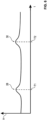
- the average field strength H of the alternating field in the area between the belt 4 and the transmitter 12 is shown schematically. If a belt area without one of the two marking parts is moved through the reference alternating field 26, there is at least essentially no change in the average field strength H. However, if the first marking part 20 with the belt 4 is guided through the reference alternating field 26, the average field strength H changes in the area 28, which is referred to as the first change in the field strength H. After the first marking part 20 is guided past the transmitter 12, the average field strength H again at least essentially assumes the previous value.
- the second ferromagnetic marking part 22 is designed to change the alternating reference field 26 into the second alternating reaction field when the alternating reference field 26 acts on the second marking part 22, or vice versa.
- the interaction between the alternating reference field 26 and the second marking part 22 creates the first alternating reaction field 26 from the alternating reference field. This represents a change compared to the alternating reference field 26.
- a corresponding change in the area 30 in the Figure 6 therefore also shows the corresponding change in the average field strength H. This is caused by the movement of the second marking part 22 through the alternating reference field 26.
- the transmitter 12 is designed to detect the second alternating reaction field and the associated second detection time T2 when the second marking part 22 is guided past the transmitter 12.
- the belt 4 is driven by the drive device 6 at a belt speed in the circumferential direction U. If, for example, the belt speed of the belt 4 is assumed to be constant, the time interval between the first detection time T1 and the second detection time T2 increases when the speed on the belt 4 increases Increase the tensile forces acting in the circumferential direction U. By increasing the tensile forces, the measuring distance M between the second marking part 22 and the first marking part 20 is increased. Corresponding to the increased measuring distance 11, the time interval between the second detection time T2 and the first detection time T1 also increases.
- the system 2 is also configured to determine the belt speed of the belt 4 in the circumferential direction U based on the first alternating reaction field and/or the second alternating reaction field.
- the transmitter 12 can be designed as or have a magnetoresistive sensor.
- the transmitter 12 of the system 2 is designed to determine the belt speed of the belt 4 in the circumferential direction U based on the first alternating reaction field and/or the second alternating reaction field.
- the transmitter 12 is coupled to the evaluation unit 14, in particular via a signal line. This means that the measurement variables recorded by the transmitter 12 are available to the evaluation unit.
- the evaluation unit 14 is configured to determine a longitudinal elongation of the belt 4 based on the reference distance R, the belt speed, the first detection time T1 and the second detection time T2. For this purpose, the following formula can be stored in the evaluation unit 14.
- the transmitter 12 faces the tension strand 52.
- the reference distance R between the second marking part 22 and the first marking part 20 is smaller than the strand length B of the tension strand 52. It is therefore preferably provided that the reference distance R is a maximum of 70% or a maximum of 50% of the strand length W of the tension strand 52.
- first marking part 20 is formed in one piece and that the second marking part 22 is formed in one piece.
- FIG. 7 An inventive design of the two marking parts 20, 22 can be seen schematically from the section of the belt 4, as shown by way of example in the Figure 7 schematic is shown.
- the front ends of the two marking parts 20, 22 are mechanically connected via connecting webs 38, 40 in such a way that the two marking parts 20, 22 and the two connecting webs 38, 40 are arranged in the manner of a frame 42 and/or are arranged circumferentially.
- the two connecting webs 38, 40 can be designed to be electrically insulating.
- a ferromagnetic frame 42 to form each of the two marking parts 20, 22 and each of the two connecting webs 38, 40.
- the frame 42 or the connecting webs 38, 40 offer the advantage that the predetermined reference distance R between the two marking parts 20, 22 is particularly easily ensured in the unloaded state of the belt 4.
Landscapes
- Engineering & Computer Science (AREA)
- General Engineering & Computer Science (AREA)
- Physics & Mathematics (AREA)
- General Physics & Mathematics (AREA)
- Mechanical Engineering (AREA)
- Aviation & Aerospace Engineering (AREA)
- Textile Engineering (AREA)
- Control Of Conveyors (AREA)
Claims (11)
- Système (2) permettant de déterminer un allongement longitudinal d'une courroie (4), présentant :une courroie (4),un dispositif d'entraînement (6) pourvu de plusieurs poulies (8, 10),un transmetteur (12), etune unité d'évaluation (14) qui peut être réalisée en combinaison avec le transmetteur (12),dans lequel la courroie (4) présente un matériau de base (16), un renfort (18), une première pièce de marquage ferromagnétique (20) et une deuxième pièce de marquage ferromagnétique (22),dans lequel le matériau de base (16) est de préférence un matériau de caoutchouc ou un matériau de polyuréthane,dans lequel la courroie (4) est réalisée de manière périphérique en anneau dans une direction circonférentielle (U),dans lequel la courroie (4) enlace les poulies (8, 10) au moins en partie et peut être entraînée par le dispositif d'entraînement (6) dans la direction circonférentielle (U),dans lequel le renfort (18) est incorporé dans le matériau de base (16) sous la forme d'une corde (24) spiralée en hélice dans la direction circonférentielle (U),dans lequel la première pièce de marquage (20) et la deuxième pièce de marquage (22) sont incorporées respectivement dans le matériau de base (16) et/ou fixées au matériau de base (16),dans lequel le transmetteur (12) est réalisé pour générer un premier champ alternatif électromagnétique qui est appelé champ alternatif de référence (26),dans lequel la première pièce de marquage ferromagnétique (20) est réalisée pour transformer le champ alternatif de référence (26) en un deuxième champ alternatif électromagnétique qui est appelé premier champ alternatif de réaction lorsque le champ alternatif de référence (26) agit sur la première pièce de marquage ferromagnétique (20),dans lequel la deuxième pièce de marquage ferromagnétique (22) est réalisée pour transformer le champ alternatif de référence (26) en un troisième champ alternatif électromagnétique qui est appelé deuxième champ alternatif de réaction lorsque le champ alternatif de référence (26) agit sur la deuxième pièce de marquage ferromagnétique (22),dans lequel la deuxième pièce de marquage (22) est disposée à une distance de référence prédéterminée (R) dans la direction circonférentielle (U) derrière la première pièce de marquage (20), au moins dans un état non chargé de la courroie (4),dans lequel le transmetteur (12) est disposé sans contact par rapport à la courroie (4) de telle sorte que la première et la deuxième pièce de marquage (22) peuvent être guidées l'une après l'autre devant le transmetteur (12) au moyen de la courroie (4) et peuvent être guidées à travers le champ alternatif de référence (26) ce qui conduit à un effet du champ alternatif de référence (26) successivement sur la première et la deuxième pièce de marquage (20, 22),dans lequel le transmetteur (12) est réalisé pour détecter le premier champ alternatif de réaction et un premier temps de détection associé (T1) lorsque la première pièce de marquage (20) est guidée devant le transmetteur (12),dans lequel le transmetteur (12) est réalisé pour détecter le deuxième champ alternatif de réaction et le deuxième temps de détection associé (T2) lorsque la deuxième pièce de marquage (22) est guidée devant le transmetteur (12),le système (2) étant configuré pour déterminer une vitesse de courroie de la courroie (2) dans la direction circonférentielle (U) sur la base du premier et/ou du deuxième champ alternatif de réaction, etdans lequel l'unité d'évaluation (14) est configurée pour déterminer un allongement longitudinal de la courroie (2) sur la base de la distance de référence (R), de la vitesse de courroie, du premier temps de détection (T1) et du deuxième temps de détection (T2),caractérisé en ce que la première et la deuxième pièce de marquage (20, 22) sont réalisées en étant reliées au moins indirectement l'une à l'autre au moyen d'entretoises de liaison (38, 40) de sorte que la distance de référence prédéterminée (R) peut être assurée sûrement à l'état non chargé de la courroie entre les deux pièces de marquage dans la direction circonférentielle.
- Système (2) selon la revendication précédente, caractérisé en ce que l'unité d'évaluation (14) est configurée pour déterminer une durée de vie restante de la courroie (4) sur la base d'un historique d'allongements longitudinaux déterminés pour la courroie (4).
- Système (2) selon l'une quelconque des revendications précédentes, caractérisé en ce que le premier temps de détection (T1) est un instant d'une transformation maximale du champ alternatif de référence (26) par la première pièce de marquage (20), et en ce que le deuxième temps de détection (T2) est un instant d'une transformation maximale du champ alternatif de référence (26) par la deuxième pièce de marquage (22).
- Système (2) selon l'une quelconque des revendications précédentes, caractérisé en ce que le transmetteur (12) est disposé sans contact sur un brin (32) de la courroie (4), en particulier sous la forme d'une partie d'une unité d'évaluation de transmetteur.
- Système (2) selon la revendication précédente, caractérisé en ce que le transmetteur (12) est disposé à une distance (A) comprise entre 1 mm et 50 cm par rapport au brin (32) de la courroie (4), en particulier sous la forme d'une partie de l'unité d'évaluation de transmetteur.
- Système (2) selon l'une quelconque des revendications précédentes, caractérisé en ce que la distance de référence (R) est inférieure à la plus petite longueur de brin (W) de la courroie (4).
- Système (2) selon l'une quelconque des revendications précédentes, caractérisé en ce que la distance de référence (R) mesure au maximum 90 %, 80 %, 70 %, 60 % ou 50 % de la longueur de brin (W).
- Système (2) selon l'une quelconque des revendications précédentes, caractérisé en ce que chaque pièce de marquage (20, 22) est réalisée de manière passive.
- Système (2) selon l'une quelconque des revendications précédentes, caractérisé en ce que chaque pièce de marquage (20, 22) est réalisée sous la forme d'une pièce de marquage (20, 22) en forme de tige et/ou de feuille, chaque pièce de marquage (20, 22) s'étendant par sa plus grande dimension transversalement à la direction circonférentielle (U).
- Système (2) selon l'une quelconque des revendications précédentes, caractérisé en ce que chaque pièce de marquage (20, 22) est préfabriquée.
- Système (2) selon l'une quelconque des revendications précédentes, caractérisé en ce que chaque pièce de marquage (20, 22) est réalisée d'un seul tenant.
Applications Claiming Priority (1)
| Application Number | Priority Date | Filing Date | Title |
|---|---|---|---|
| DE102018215478.3A DE102018215478A1 (de) | 2018-09-12 | 2018-09-12 | System |
Publications (2)
| Publication Number | Publication Date |
|---|---|
| EP3623748A1 EP3623748A1 (fr) | 2020-03-18 |
| EP3623748B1 true EP3623748B1 (fr) | 2023-11-15 |
Family
ID=67551117
Family Applications (1)
| Application Number | Title | Priority Date | Filing Date |
|---|---|---|---|
| EP19190163.6A Active EP3623748B1 (fr) | 2018-09-12 | 2019-08-06 | Système pour déterminer l'allongement longitudinal d'une courroie |
Country Status (2)
| Country | Link |
|---|---|
| EP (1) | EP3623748B1 (fr) |
| DE (1) | DE102018215478A1 (fr) |
Families Citing this family (5)
| Publication number | Priority date | Publication date | Assignee | Title |
|---|---|---|---|---|
| DE102021200478A1 (de) | 2021-01-20 | 2022-07-21 | Contitech Antriebssysteme Gmbh | Vorrichtung und Verfahren zur Ermittlung einer Längsdehnung eines Riemens |
| DE102021202803A1 (de) | 2021-03-23 | 2022-09-29 | Contitech Antriebssysteme Gmbh | Vorrichtung und Verfahren zur Ermittlung einer Längsdehnung und einer mittleren Geschwindigkeit eines Riemens, sowie zur Ermittlung einer Geschwindigkeit mindestens einer Riemenscheibe |
| EP4410714A1 (fr) * | 2023-02-06 | 2024-08-07 | ContiTech Deutschland GmbH | Bande transporteuse comprenant un empilement d'inserts de fissure magnétique imprimés stratifiés |
| DE102023207922A1 (de) | 2023-08-18 | 2025-02-20 | Robert Bosch Gesellschaft mit beschränkter Haftung | Lenkgetriebe für ein Lenksystem eines Kraftfahrzeugs mit markiertem Zahnriemen |
| DE102024207049A1 (de) * | 2024-07-26 | 2026-01-29 | Bhs Corrugated Maschinen- Und Anlagenbau Gmbh | Anpresseinheit und Verfahren zum Betrieb einer solchen sowie Anpressband und Verfahren zur Herstellung eines solchen |
Family Cites Families (7)
| Publication number | Priority date | Publication date | Assignee | Title |
|---|---|---|---|---|
| JPH082565Y2 (ja) * | 1992-03-31 | 1996-01-29 | 株式会社椿本チエイン | 無端移動体の伸び測定装置 |
| PL191431B1 (pl) * | 1998-02-13 | 2006-05-31 | Phoenix Ag | Urządzenie do ciągłego monitorowania połączenia pasa przenośnikowego |
| DE102010002551A1 (de) * | 2010-03-03 | 2011-09-08 | Arntz Beteiligungs Gmbh & Co. Kg | Riemen zur Übertragung einer Antriebsbewegung, Vorrichtung zum Antreiben eines Riemens und Verfahren zur Inbetriebnahme eines Riemens |
| DE102011051923B4 (de) * | 2011-07-19 | 2024-11-07 | Contitech Transportbandsysteme Gmbh | Einrichtung zur Überwachung einer Förderanlage zur Erfassung von Schäden eines Fördergurtes mittels sequentieller Leiterschleifen und eines sequentiellen Schlitzschutzsystems |
| DE102013111191A1 (de) * | 2013-10-10 | 2015-04-16 | Contitech Transportbandsysteme Gmbh | Verfahren und System zur berührungslosen Überwachung eines Fördergurtes auf Beschädigung |
| CN104692078B (zh) * | 2015-02-03 | 2017-01-18 | 赵磊 | 一种带式输送机运行状态监控方法 |
| JP6701042B2 (ja) * | 2016-09-20 | 2020-05-27 | 株式会社ブリヂストン | コンベヤベルトの伸び測定装置およびコンベヤベルトの伸び測定方法 |
-
2018
- 2018-09-12 DE DE102018215478.3A patent/DE102018215478A1/de not_active Withdrawn
-
2019
- 2019-08-06 EP EP19190163.6A patent/EP3623748B1/fr active Active
Also Published As
| Publication number | Publication date |
|---|---|
| DE102018215478A1 (de) | 2020-03-12 |
| EP3623748A1 (fr) | 2020-03-18 |
Similar Documents
| Publication | Publication Date | Title |
|---|---|---|
| EP3623748B1 (fr) | Système pour déterminer l'allongement longitudinal d'une courroie | |
| EP3126810B1 (fr) | Entraînement par courroie et procédé permettant de surveiller ledit entraînement | |
| EP4314756B1 (fr) | Dispositif et procédé de détermination d'une extension longitudinale et de la vitesse moyenne d'une courroie, et de détermination de la vitesse d'au moins une poulie à courroie | |
| EP2489612B1 (fr) | Agencement et procédé de surveillance d'une chaîne de transport pour un dispositif de transport et/ou d'enregistrement de l'industrie de traitement du tabac | |
| WO2017001203A1 (fr) | Procédé et dispositif de détermination d'une consommation d'énergie spécifique de convoyeurs à bande | |
| DE202019104826U1 (de) | Vorrichtung umfassend eine Energieführungskette und eine Gleitauflage | |
| WO2022156848A1 (fr) | Dispositif et procédé de détermination d'une dilatation linéaire d'une courroie | |
| EP3502013B1 (fr) | Dispositif et procédé de détermination d'une valeur de moment de dépose pour une bandoulière à fils éléctroconducteurs intégrés | |
| EP3601116B1 (fr) | Procédé pour la surveillance et le contrôle non destructif d'une bande transporteuse circulant sans fin et dispositif de diagnostic de bande transporteuse | |
| WO2022008288A1 (fr) | Dispositif et procédé de surveillance de surveillance de l'état d'une bande transporteuse d'un système de bande transporteuse | |
| WO2023274457A1 (fr) | Procédé de surveillance d'une courroie d'un entraînement par courroie | |
| EP3598096A1 (fr) | Courroie et système | |
| EP3623783B1 (fr) | Courroie, dispositif et système | |
| WO2019057352A1 (fr) | Système d'entraînement pour un système d'ascenseur ainsi que système d'ascenseur | |
| DE8900167U1 (de) | Vorrichtung zum Messen der Fadenspannung an Textilmaschinen | |
| EP3671196B1 (fr) | Système de détermination de l'état de vieillissement d'un produit élastomèrique | |
| DE102021205158A1 (de) | Riemenanlage, vorzugsweise Förderbandanlage | |
| WO2009124775A1 (fr) | Dispositif et procédé pour surveiller l’état de service de constituants en élastomères sans les détruire | |
| EP3885606B1 (fr) | Système de détection de dilatation et/ou de surveillance de l'état d'un support de renforcement d'un produit élastomère | |
| EP3597962B1 (fr) | Courroie et système | |
| AT502974B1 (de) | Verfahren zur diagnose einer kette in einem antriebssystem | |
| DE102015224562A1 (de) | Fördergurt zur Verwendung in einer Fördergurtanlage mit einem Temperaturerfassungssystem | |
| DE102024123780A1 (de) | Verfahren zur Diagnose eines Riemens in einem Zugmittelgetriebe sowie Messanordnung an einem Zugmittelgetriebe | |
| DE102024125148A1 (de) | Antriebseinheit zum Detektieren einer Abweichung eines Zustandes einer Komponente von einem Normalzustand mithilfe einer induktiven Messeinheit zum Erfassen einer Bewegung einer Antriebswelle der Antriebseinheit | |
| DE102019216124A1 (de) | Förderbandanlage mit im Förderband integrierter Datenübertragung |
Legal Events
| Date | Code | Title | Description |
|---|---|---|---|
| PUAI | Public reference made under article 153(3) epc to a published international application that has entered the european phase |
Free format text: ORIGINAL CODE: 0009012 |
|
| STAA | Information on the status of an ep patent application or granted ep patent |
Free format text: STATUS: THE APPLICATION HAS BEEN PUBLISHED |
|
| AK | Designated contracting states |
Kind code of ref document: A1 Designated state(s): AL AT BE BG CH CY CZ DE DK EE ES FI FR GB GR HR HU IE IS IT LI LT LU LV MC MK MT NL NO PL PT RO RS SE SI SK SM TR |
|
| AX | Request for extension of the european patent |
Extension state: BA ME |
|
| STAA | Information on the status of an ep patent application or granted ep patent |
Free format text: STATUS: REQUEST FOR EXAMINATION WAS MADE |
|
| 17P | Request for examination filed |
Effective date: 20200918 |
|
| RBV | Designated contracting states (corrected) |
Designated state(s): AL AT BE BG CH CY CZ DE DK EE ES FI FR GB GR HR HU IE IS IT LI LT LU LV MC MK MT NL NO PL PT RO RS SE SI SK SM TR |
|
| STAA | Information on the status of an ep patent application or granted ep patent |
Free format text: STATUS: EXAMINATION IS IN PROGRESS |
|
| 17Q | First examination report despatched |
Effective date: 20211021 |
|
| GRAP | Despatch of communication of intention to grant a patent |
Free format text: ORIGINAL CODE: EPIDOSNIGR1 |
|
| STAA | Information on the status of an ep patent application or granted ep patent |
Free format text: STATUS: GRANT OF PATENT IS INTENDED |
|
| RIC1 | Information provided on ipc code assigned before grant |
Ipc: F16G 5/14 20060101ALI20230721BHEP Ipc: F16G 5/10 20060101ALI20230721BHEP Ipc: F16G 5/08 20060101ALI20230721BHEP Ipc: F16G 1/12 20060101ALI20230721BHEP Ipc: B65G 43/02 20060101ALI20230721BHEP Ipc: B65G 15/30 20060101ALI20230721BHEP Ipc: G01M 13/023 20190101ALI20230721BHEP Ipc: G01L 1/12 20060101ALI20230721BHEP Ipc: G01B 7/24 20060101AFI20230721BHEP |
|
| INTG | Intention to grant announced |
Effective date: 20230809 |
|
| GRAS | Grant fee paid |
Free format text: ORIGINAL CODE: EPIDOSNIGR3 |
|
| GRAA | (expected) grant |
Free format text: ORIGINAL CODE: 0009210 |
|
| STAA | Information on the status of an ep patent application or granted ep patent |
Free format text: STATUS: THE PATENT HAS BEEN GRANTED |
|
| AK | Designated contracting states |
Kind code of ref document: B1 Designated state(s): AL AT BE BG CH CY CZ DE DK EE ES FI FR GB GR HR HU IE IS IT LI LT LU LV MC MK MT NL NO PL PT RO RS SE SI SK SM TR |
|
| P01 | Opt-out of the competence of the unified patent court (upc) registered |
Effective date: 20231006 |
|
| REG | Reference to a national code |
Ref country code: CH Ref legal event code: EP Ref country code: GB Ref legal event code: FG4D Free format text: NOT ENGLISH |
|
| REG | Reference to a national code |
Ref country code: DE Ref legal event code: R096 Ref document number: 502019009909 Country of ref document: DE |
|
| REG | Reference to a national code |
Ref country code: IE Ref legal event code: FG4D Free format text: LANGUAGE OF EP DOCUMENT: GERMAN |
|
| REG | Reference to a national code |
Ref country code: LT Ref legal event code: MG9D |
|
| REG | Reference to a national code |
Ref country code: NL Ref legal event code: MP Effective date: 20231115 |
|
| PG25 | Lapsed in a contracting state [announced via postgrant information from national office to epo] |
Ref country code: GR Free format text: LAPSE BECAUSE OF FAILURE TO SUBMIT A TRANSLATION OF THE DESCRIPTION OR TO PAY THE FEE WITHIN THE PRESCRIBED TIME-LIMIT Effective date: 20240216 |
|
| PG25 | Lapsed in a contracting state [announced via postgrant information from national office to epo] |
Ref country code: IS Free format text: LAPSE BECAUSE OF FAILURE TO SUBMIT A TRANSLATION OF THE DESCRIPTION OR TO PAY THE FEE WITHIN THE PRESCRIBED TIME-LIMIT Effective date: 20240315 |
|
| PG25 | Lapsed in a contracting state [announced via postgrant information from national office to epo] |
Ref country code: LT Free format text: LAPSE BECAUSE OF FAILURE TO SUBMIT A TRANSLATION OF THE DESCRIPTION OR TO PAY THE FEE WITHIN THE PRESCRIBED TIME-LIMIT Effective date: 20231115 |
|
| PG25 | Lapsed in a contracting state [announced via postgrant information from national office to epo] |
Ref country code: NL Free format text: LAPSE BECAUSE OF FAILURE TO SUBMIT A TRANSLATION OF THE DESCRIPTION OR TO PAY THE FEE WITHIN THE PRESCRIBED TIME-LIMIT Effective date: 20231115 |
|
| PG25 | Lapsed in a contracting state [announced via postgrant information from national office to epo] |
Ref country code: ES Free format text: LAPSE BECAUSE OF FAILURE TO SUBMIT A TRANSLATION OF THE DESCRIPTION OR TO PAY THE FEE WITHIN THE PRESCRIBED TIME-LIMIT Effective date: 20231115 |
|
| PG25 | Lapsed in a contracting state [announced via postgrant information from national office to epo] |
Ref country code: NL Free format text: LAPSE BECAUSE OF FAILURE TO SUBMIT A TRANSLATION OF THE DESCRIPTION OR TO PAY THE FEE WITHIN THE PRESCRIBED TIME-LIMIT Effective date: 20231115 Ref country code: LT Free format text: LAPSE BECAUSE OF FAILURE TO SUBMIT A TRANSLATION OF THE DESCRIPTION OR TO PAY THE FEE WITHIN THE PRESCRIBED TIME-LIMIT Effective date: 20231115 Ref country code: IS Free format text: LAPSE BECAUSE OF FAILURE TO SUBMIT A TRANSLATION OF THE DESCRIPTION OR TO PAY THE FEE WITHIN THE PRESCRIBED TIME-LIMIT Effective date: 20240315 Ref country code: GR Free format text: LAPSE BECAUSE OF FAILURE TO SUBMIT A TRANSLATION OF THE DESCRIPTION OR TO PAY THE FEE WITHIN THE PRESCRIBED TIME-LIMIT Effective date: 20240216 Ref country code: ES Free format text: LAPSE BECAUSE OF FAILURE TO SUBMIT A TRANSLATION OF THE DESCRIPTION OR TO PAY THE FEE WITHIN THE PRESCRIBED TIME-LIMIT Effective date: 20231115 Ref country code: BG Free format text: LAPSE BECAUSE OF FAILURE TO SUBMIT A TRANSLATION OF THE DESCRIPTION OR TO PAY THE FEE WITHIN THE PRESCRIBED TIME-LIMIT Effective date: 20240215 Ref country code: PT Free format text: LAPSE BECAUSE OF FAILURE TO SUBMIT A TRANSLATION OF THE DESCRIPTION OR TO PAY THE FEE WITHIN THE PRESCRIBED TIME-LIMIT Effective date: 20240315 |
|
| PG25 | Lapsed in a contracting state [announced via postgrant information from national office to epo] |
Ref country code: SE Free format text: LAPSE BECAUSE OF FAILURE TO SUBMIT A TRANSLATION OF THE DESCRIPTION OR TO PAY THE FEE WITHIN THE PRESCRIBED TIME-LIMIT Effective date: 20231115 Ref country code: RS Free format text: LAPSE BECAUSE OF FAILURE TO SUBMIT A TRANSLATION OF THE DESCRIPTION OR TO PAY THE FEE WITHIN THE PRESCRIBED TIME-LIMIT Effective date: 20231115 Ref country code: PL Free format text: LAPSE BECAUSE OF FAILURE TO SUBMIT A TRANSLATION OF THE DESCRIPTION OR TO PAY THE FEE WITHIN THE PRESCRIBED TIME-LIMIT Effective date: 20231115 Ref country code: NO Free format text: LAPSE BECAUSE OF FAILURE TO SUBMIT A TRANSLATION OF THE DESCRIPTION OR TO PAY THE FEE WITHIN THE PRESCRIBED TIME-LIMIT Effective date: 20240215 Ref country code: LV Free format text: LAPSE BECAUSE OF FAILURE TO SUBMIT A TRANSLATION OF THE DESCRIPTION OR TO PAY THE FEE WITHIN THE PRESCRIBED TIME-LIMIT Effective date: 20231115 Ref country code: HR Free format text: LAPSE BECAUSE OF FAILURE TO SUBMIT A TRANSLATION OF THE DESCRIPTION OR TO PAY THE FEE WITHIN THE PRESCRIBED TIME-LIMIT Effective date: 20231115 |
|
| PG25 | Lapsed in a contracting state [announced via postgrant information from national office to epo] |
Ref country code: DK Free format text: LAPSE BECAUSE OF FAILURE TO SUBMIT A TRANSLATION OF THE DESCRIPTION OR TO PAY THE FEE WITHIN THE PRESCRIBED TIME-LIMIT Effective date: 20231115 |
|
| PG25 | Lapsed in a contracting state [announced via postgrant information from national office to epo] |
Ref country code: CZ Free format text: LAPSE BECAUSE OF FAILURE TO SUBMIT A TRANSLATION OF THE DESCRIPTION OR TO PAY THE FEE WITHIN THE PRESCRIBED TIME-LIMIT Effective date: 20231115 |
|
| PG25 | Lapsed in a contracting state [announced via postgrant information from national office to epo] |
Ref country code: SK Free format text: LAPSE BECAUSE OF FAILURE TO SUBMIT A TRANSLATION OF THE DESCRIPTION OR TO PAY THE FEE WITHIN THE PRESCRIBED TIME-LIMIT Effective date: 20231115 |
|
| PG25 | Lapsed in a contracting state [announced via postgrant information from national office to epo] |
Ref country code: SM Free format text: LAPSE BECAUSE OF FAILURE TO SUBMIT A TRANSLATION OF THE DESCRIPTION OR TO PAY THE FEE WITHIN THE PRESCRIBED TIME-LIMIT Effective date: 20231115 Ref country code: SK Free format text: LAPSE BECAUSE OF FAILURE TO SUBMIT A TRANSLATION OF THE DESCRIPTION OR TO PAY THE FEE WITHIN THE PRESCRIBED TIME-LIMIT Effective date: 20231115 Ref country code: RO Free format text: LAPSE BECAUSE OF FAILURE TO SUBMIT A TRANSLATION OF THE DESCRIPTION OR TO PAY THE FEE WITHIN THE PRESCRIBED TIME-LIMIT Effective date: 20231115 Ref country code: IT Free format text: LAPSE BECAUSE OF FAILURE TO SUBMIT A TRANSLATION OF THE DESCRIPTION OR TO PAY THE FEE WITHIN THE PRESCRIBED TIME-LIMIT Effective date: 20231115 Ref country code: EE Free format text: LAPSE BECAUSE OF FAILURE TO SUBMIT A TRANSLATION OF THE DESCRIPTION OR TO PAY THE FEE WITHIN THE PRESCRIBED TIME-LIMIT Effective date: 20231115 Ref country code: DK Free format text: LAPSE BECAUSE OF FAILURE TO SUBMIT A TRANSLATION OF THE DESCRIPTION OR TO PAY THE FEE WITHIN THE PRESCRIBED TIME-LIMIT Effective date: 20231115 Ref country code: CZ Free format text: LAPSE BECAUSE OF FAILURE TO SUBMIT A TRANSLATION OF THE DESCRIPTION OR TO PAY THE FEE WITHIN THE PRESCRIBED TIME-LIMIT Effective date: 20231115 |
|
| REG | Reference to a national code |
Ref country code: DE Ref legal event code: R097 Ref document number: 502019009909 Country of ref document: DE |
|
| PLBE | No opposition filed within time limit |
Free format text: ORIGINAL CODE: 0009261 |
|
| STAA | Information on the status of an ep patent application or granted ep patent |
Free format text: STATUS: NO OPPOSITION FILED WITHIN TIME LIMIT |
|
| 26N | No opposition filed |
Effective date: 20240819 |
|
| PG25 | Lapsed in a contracting state [announced via postgrant information from national office to epo] |
Ref country code: SI Free format text: LAPSE BECAUSE OF FAILURE TO SUBMIT A TRANSLATION OF THE DESCRIPTION OR TO PAY THE FEE WITHIN THE PRESCRIBED TIME-LIMIT Effective date: 20231115 |
|
| PG25 | Lapsed in a contracting state [announced via postgrant information from national office to epo] |
Ref country code: SI Free format text: LAPSE BECAUSE OF FAILURE TO SUBMIT A TRANSLATION OF THE DESCRIPTION OR TO PAY THE FEE WITHIN THE PRESCRIBED TIME-LIMIT Effective date: 20231115 |
|
| REG | Reference to a national code |
Ref country code: CH Ref legal event code: PL |
|
| PG25 | Lapsed in a contracting state [announced via postgrant information from national office to epo] |
Ref country code: LU Free format text: LAPSE BECAUSE OF NON-PAYMENT OF DUE FEES Effective date: 20240806 |
|
| PG25 | Lapsed in a contracting state [announced via postgrant information from national office to epo] |
Ref country code: CH Free format text: LAPSE BECAUSE OF NON-PAYMENT OF DUE FEES Effective date: 20240831 Ref country code: MC Free format text: LAPSE BECAUSE OF FAILURE TO SUBMIT A TRANSLATION OF THE DESCRIPTION OR TO PAY THE FEE WITHIN THE PRESCRIBED TIME-LIMIT Effective date: 20231115 |
|
| REG | Reference to a national code |
Ref country code: BE Ref legal event code: MM Effective date: 20240831 |
|
| PG25 | Lapsed in a contracting state [announced via postgrant information from national office to epo] |
Ref country code: BE Free format text: LAPSE BECAUSE OF NON-PAYMENT OF DUE FEES Effective date: 20240831 |
|
| PG25 | Lapsed in a contracting state [announced via postgrant information from national office to epo] |
Ref country code: IE Free format text: LAPSE BECAUSE OF NON-PAYMENT OF DUE FEES Effective date: 20240806 |
|
| PG25 | Lapsed in a contracting state [announced via postgrant information from national office to epo] |
Ref country code: FI Free format text: LAPSE BECAUSE OF FAILURE TO SUBMIT A TRANSLATION OF THE DESCRIPTION OR TO PAY THE FEE WITHIN THE PRESCRIBED TIME-LIMIT Effective date: 20231115 |
|
| PGFP | Annual fee paid to national office [announced via postgrant information from national office to epo] |
Ref country code: DE Payment date: 20250831 Year of fee payment: 7 |
|
| REG | Reference to a national code |
Ref country code: AT Ref legal event code: MM01 Ref document number: 1632139 Country of ref document: AT Kind code of ref document: T Effective date: 20240806 |
|
| PGFP | Annual fee paid to national office [announced via postgrant information from national office to epo] |
Ref country code: GB Payment date: 20250820 Year of fee payment: 7 |
|
| PG25 | Lapsed in a contracting state [announced via postgrant information from national office to epo] |
Ref country code: AT Free format text: LAPSE BECAUSE OF NON-PAYMENT OF DUE FEES Effective date: 20240806 |
|
| PGFP | Annual fee paid to national office [announced via postgrant information from national office to epo] |
Ref country code: FR Payment date: 20250828 Year of fee payment: 7 |
|
| PG25 | Lapsed in a contracting state [announced via postgrant information from national office to epo] |
Ref country code: CY Free format text: LAPSE BECAUSE OF FAILURE TO SUBMIT A TRANSLATION OF THE DESCRIPTION OR TO PAY THE FEE WITHIN THE PRESCRIBED TIME-LIMIT; INVALID AB INITIO Effective date: 20190806 |
|
| PG25 | Lapsed in a contracting state [announced via postgrant information from national office to epo] |
Ref country code: HU Free format text: LAPSE BECAUSE OF FAILURE TO SUBMIT A TRANSLATION OF THE DESCRIPTION OR TO PAY THE FEE WITHIN THE PRESCRIBED TIME-LIMIT; INVALID AB INITIO Effective date: 20190806 |
|
| REG | Reference to a national code |
Ref country code: DE Ref legal event code: R081 Ref document number: 502019009909 Country of ref document: DE Owner name: CONTITECH DEUTSCHLAND GMBH, DE Free format text: FORMER OWNER: CONTITECH ANTRIEBSSYSTEME GMBH, 30165 HANNOVER, DE |