EP3624184A1 - Procédé de fabrication d'une unité de module de puissance, unité de module de puissance, bloc d'alimentation et convertisseur de fréquence - Google Patents
Procédé de fabrication d'une unité de module de puissance, unité de module de puissance, bloc d'alimentation et convertisseur de fréquence Download PDFInfo
- Publication number
- EP3624184A1 EP3624184A1 EP18194020.6A EP18194020A EP3624184A1 EP 3624184 A1 EP3624184 A1 EP 3624184A1 EP 18194020 A EP18194020 A EP 18194020A EP 3624184 A1 EP3624184 A1 EP 3624184A1
- Authority
- EP
- European Patent Office
- Prior art keywords
- base plate
- cooling fin
- power module
- module unit
- recess
- Prior art date
- Legal status (The legal status is an assumption and is not a legal conclusion. Google has not performed a legal analysis and makes no representation as to the accuracy of the status listed.)
- Withdrawn
Links
Images

Classifications
-
- H—ELECTRICITY
- H05—ELECTRIC TECHNIQUES NOT OTHERWISE PROVIDED FOR
- H05K—PRINTED CIRCUITS; CASINGS OR CONSTRUCTIONAL DETAILS OF ELECTRIC APPARATUS; MANUFACTURE OF ASSEMBLAGES OF ELECTRICAL COMPONENTS
- H05K7/00—Constructional details common to different types of electric apparatus
- H05K7/20—Modifications to facilitate cooling, ventilating, or heating
- H05K7/2089—Modifications to facilitate cooling, ventilating, or heating for power electronics, e.g. for inverters for controlling motor
- H05K7/20936—Liquid coolant with phase change
-
- H—ELECTRICITY
- H10—SEMICONDUCTOR DEVICES; ELECTRIC SOLID-STATE DEVICES NOT OTHERWISE PROVIDED FOR
- H10W—GENERIC PACKAGES, INTERCONNECTIONS, CONNECTORS OR OTHER CONSTRUCTIONAL DETAILS OF DEVICES COVERED BY CLASS H10
- H10W40/00—Arrangements for thermal protection or thermal control
- H10W40/01—Manufacture or treatment
- H10W40/03—Manufacture or treatment of arrangements for cooling
- H10W40/037—Assembling together parts thereof
-
- H—ELECTRICITY
- H10—SEMICONDUCTOR DEVICES; ELECTRIC SOLID-STATE DEVICES NOT OTHERWISE PROVIDED FOR
- H10W—GENERIC PACKAGES, INTERCONNECTIONS, CONNECTORS OR OTHER CONSTRUCTIONAL DETAILS OF DEVICES COVERED BY CLASS H10
- H10W40/00—Arrangements for thermal protection or thermal control
- H10W40/20—Arrangements for cooling
- H10W40/22—Arrangements for cooling characterised by their shape, e.g. having conical or cylindrical projections
- H10W40/226—Arrangements for cooling characterised by their shape, e.g. having conical or cylindrical projections characterised by projecting parts, e.g. fins to increase surface area
-
- H—ELECTRICITY
- H10—SEMICONDUCTOR DEVICES; ELECTRIC SOLID-STATE DEVICES NOT OTHERWISE PROVIDED FOR
- H10W—GENERIC PACKAGES, INTERCONNECTIONS, CONNECTORS OR OTHER CONSTRUCTIONAL DETAILS OF DEVICES COVERED BY CLASS H10
- H10W40/00—Arrangements for thermal protection or thermal control
- H10W40/20—Arrangements for cooling
- H10W40/25—Arrangements for cooling characterised by their materials
- H10W40/258—Metallic materials
-
- H—ELECTRICITY
- H10—SEMICONDUCTOR DEVICES; ELECTRIC SOLID-STATE DEVICES NOT OTHERWISE PROVIDED FOR
- H10W—GENERIC PACKAGES, INTERCONNECTIONS, CONNECTORS OR OTHER CONSTRUCTIONAL DETAILS OF DEVICES COVERED BY CLASS H10
- H10W40/00—Arrangements for thermal protection or thermal control
- H10W40/40—Arrangements for thermal protection or thermal control involving heat exchange by flowing fluids
- H10W40/43—Arrangements for thermal protection or thermal control involving heat exchange by flowing fluids by flowing gases, e.g. forced air cooling
Definitions
- the invention relates to a method for producing a power module unit and a power module unit.
- the invention relates to a power supply and a frequency converter.
- Power modules generally comprise a substrate with a power semiconductor, for example an IGBT (Insulated Gate Bipolar Transistor), which is firmly connected to a substrate.
- the substrate has a metal structure on both sides, the metal structure being formed on one side for connection to the power semiconductor and being attachable to a base plate on the other side.
- the base plate is preferably subjected to a heat-conducting structure and fastened on a heat sink.
- a complex pre-bending of the base plate is necessary so that the base plate is firmly connected to the heat sink even at a temperature of more than 100 degrees Celsius.
- the unit comprising a power module and a heat sink, is referred to here as a power module unit
- a base plate on one side with heat-conducting Form structures in one piece is attached to the opposite side of the base plate.
- the object is achieved by a power module unit according to claim 1.
- the object is further achieved by a frequency converter or a power supply according to claim 10.
- the object is also achieved by a method according to claim 11.
- the invention is based on the finding that direct application of the substrate with the power semiconductor to the base plate replaces a material boundary between the base plate and the heat sink.
- the substrate is preferably attached to the base plate of the heat sink with a solder connection.
- the base plate thus serves on the first side as a carrier for the substrate.
- the second side of the base plate is also used to attach the cooling fins.
- the invention is based on the insight that it is advantageous only the base plate with the substrate in the furnace to heat and to fix the cooling fins in the recesses of the base plate after fastening the substrate.
- the cooling fins are preferably attached in such a way that the base plate is not bent with the substrate. Bending the baseplate could damage the substrate.
- cooling fins can advantageously be introduced into the respective recess in the tangential direction to the first side.
- the substrate preferably comprises a ceramic layer, the ceramic layer having a metal layer on the upper side and the lower side, at least in regions.
- the metal layer preferably comprises copper, silver or tin.
- the metal layer, which is preferably applied in regions, on the upper side of the substrate serves to fasten the power semiconductor.
- the metal layer preferably applied on the underside, serves for soldering, pressing or sintering the substrate to the base plate.
- the power module unit has a base plate with at least one cutout on a first side, at least one cooling fin being fastened in the respective cutout, the respective cooling fin being embodied in each case in a cutout in the base plate by an at least partially positive, partially cohesive and / or partially non-positive Connection is attached, wherein the base plate has a substrate for a power semiconductor on a second side.
- the power module unit optionally also includes a housing which protects the substrate from environmental influences.
- the substrate serves as the basis for power semiconductors such as an IGBT or a thyristor. Several power semiconductors can also be attached to the substrate.
- the recess preferably runs along the first side from one end of the base plate to the other end of the base plate.
- the recess advantageously serves to receive one or more cooling fins.
- the respective cooling fin is preferably inserted into the recess in the base plate when the substrate is already attached to the base plate on the second side.
- the power module unit preferably additionally comprises a housing, the housing covering the second side at least in regions.
- the housing serves to cover and thus to protect the substrate or the at least one power semiconductor.
- a cohesive connection is understood to mean, for example, a soldered connection, an adhesive connection or a welded connection.
- connection of the cooling fin to the base plate is preferably at least partially positive.
- the positive connection creates a good thermal connection between the base plate and the respective cooling fin.
- the positive connection therefore serves to improve the dissipation of waste heat from the power semiconductors via the base plate onto the cooling fins.
- the cooling fins are preferably fastened to the base plate by a force-fit connection in such a way that the cooling fins are inserted into a heated base plate and form a force-fit connection when the base plate cools.
- the cooling fins can also be cooled during insertion and form a non-positive connection by heating to room temperature.
- the respective cooling fin is connected to the base plate by a press connection, an adhesive connection or a solder connection.
- the respective cooling fin can be fastened in the cutout of the base plate with a soldered connection or an adhesive connection.
- the power module unit is designed to be stable against external influences by means of a fixed connection of the respective cooling fin to the base plate.
- a good connection between the respective cooling fin and the base plate ensures good and safe heat transfer from the power semiconductor to the cooling fins.
- the base plate has copper, aluminum or a layer of copper and a layer of aluminum.
- Copper is preferably used as the material for receiving the substrate because it is well suited for establishing a solder connection and is a good heat conductor.
- Aluminum is preferably used as the material for the base plate, because aluminum is a good heat conductor on the one hand and, due to its good deformability, is also suitable for a positive connection of the base plate to the cooling fins.
- the base plate is particularly advantageously formed from two metal layers firmly connected to one another.
- a base plate has an aluminum layer adjacent to the first side, which has a copper layer on its upper side.
- Both metal layers are, for example, firmly connected to one another by a rolling process.
- the layers can also be connected to one another by a soldering process, in particular using a high-temperature soldering process.
- Such a layer has the advantages mentioned above and is commercially available.
- the respective cooling fin has an attachment on at least one side, the attachment touching the first side of the base plate after the cooling fin has been introduced.
- the attachment serves to limit the penetration of the cooling fin into the recess in such a way that a bottom side of the recess merely touches the cooling fin.
- the attachment can protrude into the recess in certain areas.
- the cutout has, at its edges, side surfaces which are oriented obliquely with the first side. The side surfaces serve to accommodate the side surface of the attachment, which is also inclined.
- the attachment can reduce the load on the base plate when the respective cooling fin is introduced into the recess.
- the bending stress which induces a force perpendicular to the first side of the base plate, can be reduced effectively.
- the connection of the substrate to the base plate is brought about a reduced load when the cooling fins are introduced into the recess.
- the respective cooling fin has copper, aluminum or an alloy.
- the cooling fin is preferably made of a material with good heat conduction, in particular aluminum, an aluminum alloy, copper or a copper alloy.
- the heat can be efficiently removed from the base plate.
- the attachment of the base plate to the respective cooling fin is reinforced by notches and embossments.
- At least part of the cutouts in the base plate and / or the cooling fins preferably have notches and / or impressions.
- the recesses can emboss notches in the cooling fin when the cooling fin is introduced into the respective recess.
- the notches form a positive connection at least in some areas.
- Imprints of the cooling fin preferably protrude into notches in the respective recess. This enables a particularly firm connection.
- the characteristics in the respective cutout therefore serve to improve the connection of the cooling fins to the base plate.
- the hardness of the material for the base plate and the hardness of the material for the respective cooling fin are different.
- the base plate preferably has a material with a greater hardness than the material of the cooling fins. In this way, the material of the cooling fin is slightly deformed and an at least partially positive connection is formed between the base plate and the cooling fin.
- the cooling fin and / or the inside of the recess in the base plate is advantageously slightly deformed when the cooling fin is introduced into the respective recess.
- impressions contribute to the deformation of the cooling fin and / or the deformation of the base plate.
- the material of the cooling fin can be made harder than the material of the base plate. Such an embodiment preferably leads to a simplified manufacture of the power module unit.
- the respective cooling fin is U-shaped, O-shaped or 8-shaped.
- the cooling fin preferably has an opening.
- the opening is preferably used for the passage of a cooling medium such as an air stream.
- the opening is preferably designed such that a cross section of the cooling fin is hollow on the inside.
- the cross section of the respective cooling fin is therefore preferably 0-shaped.
- the cooling fin is preferably formed in the middle with a reinforcement, in particular a material transition.
- This material transition leads to an 8-shaped cross section of the cooling fin.
- a cross section of the respective recess is tapered toward the second side, preferably trapezoidal.
- the recess is tapered towards the inside.
- the recess is preferably trapezoidal. If necessary, embossments are positioned on the sides of the inner surface of the respective cutouts. The impressions are preferably used to fix the cooling fin in the recess.
- the recess tapered inwards advantageously protects the substrate of the power module unit when the respective cooling fin is introduced.
- further cooling fins are positioned between the cooling fins, the respective further cooling fin and the cooling fin only overlapping laterally in some areas.
- the further cooling fins are preferably non-positively connected to the cooling fins.
- the further cooling fins and the cooling fins preferably overlap with a width of 1 centimeter to 2 centimeters.
- the sides of the cooling fins are preferably formed with a ribbed structure at least in the region in which the cooling fins and the further cooling fins overlap.
- a ribbed structure is understood in particular to mean that the side of the respective cooling fin and / or the side of the respective further cooling fin has impressions.
- the embossing can have a triangular cross section.
- the impressions are preferably aligned parallel to one another.
- the stampings are advantageously aligned parallel to the edge of the cooling fin.
- Notches are preferably positioned between the impressions.
- the notches preferably have a triangular cross section.
- the impressions of the cooling fin preferably protrude into the notches of the respectively adjacent further cooling fin.
- the cooling capacity of the power module unit can be increased subsequently.
- the cooling fin is formed at least in regions from carbon, for example from graphite.
- the cooling fin can advantageously be formed at least in regions from carbon nanotubes or comprise carbon nanotubes.
- Graphite or carbon nanotubes in particular have a particularly high thermal conductivity.
- the cooling of the base plate can be improved by the high thermal conductivity.
- cooling fins are connected to one another.
- the cooling fins are advantageously connected by connecting elements.
- the connecting elements and the cooling fins preferably form a unit.
- the unit will advantageously be inserted as a whole into the cutouts in the base plate.
- the connecting elements are preferably integrally connected to the cooling fins.
- the cooling fins and the connecting elements are preferably made in one piece.
- the connecting elements preferably have openings.
- the openings are advantageously used to reduce weight.
- the openings are preferably designed to carry out a cooling medium, in particular a cooling air flow.
- the unit enables a particularly firm and even connection of the cooling fins to the base plate. Furthermore, heat can be transferred from one cooling fin to another cooling fin.
- cooling fins are connected to one another with connecting elements to form a unit.
- the units are preferably designed such that a unit can be connected to a further unit by means of a plug connection, a press connection or an adhesive connection.
- the unit preferably has cooling fins oriented in parallel, cooling fins being connected to one another by the connecting elements.
- the cooling fins preferably have a structured surface at both ends, in particular a ribbed surface.
- the structured surface enables an improved connection of the cooling fins to one another, a cooling fin preferably being inserted between two other cooling fins for the connection.
- the structured surface serves to improve the cohesion of the cooling fins with one another.
- the cooling fins are fixed together by the connecting elements.
- An advantageous application of the power module unit described here is a frequency converter or power supply unit, in particular for industrial use.
- Such a frequency converter is advantageously used for mobile applications such as at least partially electrically powered vehicles.
- the invention is also advantageously applicable to electrically powered aircraft.
- the invention can be used advantageously for a charger.
- the invention is preferably applied to a charger for an electrically powered vehicle or aircraft.
- the type, number, shape and size of the cooling fins can advantageously be selected in accordance with the cooling requirements of the power module unit in the respective application.
- the base plate with the substrate is preferably heated in an oven.
- the substrate and the base plate are heated to a temperature between 200 and 500 degrees.
- the heating serves to form a solder, sinter or press connection from the substrate to the base plate.
- the cooling fins are preferably introduced together in a recess provided for the cooling fin. For this purpose, the cooling fins are aligned and the base plate is pressed on.
- the cutouts are made in the base plate after the substrate has been fastened.
- the cutouts are preferably introduced into the base plate by machining. By inserting the recess later, the base plate can be heated in an oven without recesses.
- the cuboid design of the base plate allows the base plate to be heated particularly uniformly and is particularly stable when the base plate is press-connected to the substrate.
- the material of the base plate and the material of the respective cooling fin can be selected such that the cross section of the recess of the base plate is enlarged in the case of a heated base plate and one at room temperature around the part of the cooling fin that is located in the recess forms non-positive and / or positive connection.
- a soldered connection or an adhesive connection can also contribute to fastening the respective cooling fin to the base plate.
- the cooling fins can be selected according to the respective application by means of the method for producing the power module unit described above. At the same time, time is saved when connecting the base plate to the substrate because the cooling fins do not have to be heated. In addition, by heating the base plate without cooling fins, a particularly uniform temperature distribution is possible, which leads to an improved soldering or sintering connection of the substrate to the base plate.
- the height of the furnace can advantageously be made particularly low.
- the base plate and the substrate are heated in an oven.
- the base plate and the substrate on the base plate are preferably heated in a continuous furnace. By simply changing the throughput time of the base plates through the furnace, the necessary heating of the base plate and the substrate can be set well.
- the cooling fin is introduced into the recess after the base plate has cooled.
- the base plate is preferably cooled to room temperature before the cooling fin is introduced.
- the base plate By cooling the base plate, bending of impressions in the recess can be prevented when a cooling fin is introduced.
- an improved hold is possible with an adhesive connection of the cooling fins to the base plate.
- cooling fins are introduced into the respective recess along the recess.
- the force that causes the base plate to bend should be avoided. Since the base plate is more stable to the sides along the tangential direction, introducing the at least one cooling fin in the tangential direction leads to a slight deformation of the base plate and thus to a low load on the substrate.
- the respective cooling fin comprises an opening, a pressing means being guided into the opening of the cooling fin and the cooling fin being pressed into the recess with the aid of the pressing means.
- the pressing means can contribute to the formation of a positive connection.
- the pressing means preferably deforms the respective end of the cooling fin, so that the material of the cooling fin fills the recess at least in some areas.
- a rod can be used as the pressing medium.
- the pressing means is preferably passed through an opening of the cooling fin and the cooling fin is introduced into the recess. Bending of the cooling fin can be effectively prevented by using a pressing agent which acts on the cooling fin in the vicinity of the cutout.
- FIG. 1 shows an exemplary power module unit 1.
- the power module unit 1 comprises a base plate 3, the base plate 3 having cutouts 9 on a first side.
- the cutouts 9 each serve to receive at least one cooling fin 7.
- the base plate has a substrate 4 on a second side 3b.
- the substrate 4 serves as a carrier for the power semiconductors 5.
- the substrate is preferably made from a ceramic, the substrate having a copper coating on both sides.
- the copper coating serves in particular as the basis of a solder connection 11 for fastening the substrate 4 to the base plate 3.
- the power semiconductors 5 are preferably likewise connected to the substrate 4 by a solder connection 11.
- the base plate 3 is preferably formed from a copper or an aluminum alloy.
- the base plate 3 is particularly advantageously made of aluminum in the lower region, adjacent to the first side 3a, and made of copper in the upper region, adjacent to the second side 3b.
- the basis for such a base plate 3 is a layered material. A possible layered structure is indicated by the dashed line in the base plate 3.
- the respective cooling fin is fastened to the base plate 3 by a positive and / or non-positive connection in the respective recess 9 of the base plate 3.
- FIG 2 shows a section of an exemplary power module unit 1. Shown is a base plate 3 with a plurality of cooling fins 7.
- the cooling fins 7 are each introduced in one of the cutouts 9 in the base plate 3.
- the cooling fins 7 shown each have two openings 7a.
- the openings 8 are separated from one another by a boundary in the center of the cooling fin 7.
- An 8-shaped profile of the cooling fin is thus formed. The 8-shaped profile allows an air flow to cool the cooling fin particularly efficiently.
- the cooling fin 7 is reinforced at the respective end 7b of the cooling fin 7. Such reinforcement can be achieved by increasing the wall thickness of the cooling fin 7 in the area of its respective end 7a. By reinforcing the cooling fin 7 at its respective end 7a, a particularly stable connection of the respective cooling fin 7 to the base plate 3 is possible.
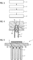
- FIG 3 shows an exemplary method.
- the method comprises a first step a, a second step b, a third, optional step c and a fourth step d.
- the respective recess 9 is made in the base plate 3.
- the recess is stamped into the base plate by a rolling process, a machining process such as milling or a forging process.
- a substrate 4 is positioned on the second side 3b of the base plate 3.
- the base plate with the substrate is heated in a furnace to a temperature of 200 degrees to 500 degrees Celsius.
- the substrate 4 is firmly connected to the second side 3b of the base plate by a solder connection or a sinter connection.
- step c the base plate with the substrate is cooled again to room temperature.
- the cooling takes place quickly or slowly.
- a fourth step d the cooling fins 7 are introduced into the respective recess 9 of the base plate and fastened.
- the cooling fins are introduced either from the side, that is to say tangentially to the first side 3a of the base plate 3, or perpendicularly thereto.
- the cooling fins 7 are introduced tangentially into the base plate, the cooling fin 7 is pushed into the recess orthogonally to the cross section 9a of the recess 9.
- Such insertion advantageously deforms the base plate only minimally.
- FIG 4 shows a possible cross section 9a of a recess 9.
- the recess 9 of the base plate 3 is tapered inwards.
- the recess 9 has impressions 10 on its inside 9b.
- the impressions 10 are advantageously used to form interlocking connections between the base plate 3 (shown here as a detail) and the cooling fin 7.
- the trapezoidal cross section 9a of the recess 9 serves to reduce the force which is perpendicular to the first when the cooling fin 7 is introduced into the recess 9 vertically Side 3a or second side 3b of the base plate 3 acts. Rather, the force is deflected in the direction tangential to the respective side 3a, 3b of the base plate 3. This is shown by the arrows that start from the recess.
- a pressing means 11 is also indicated in the figure.
- the pressing means 11 serves to introduce the cooling fin 7 into the recess 9.
- the pressing means 11 is preferably designed as a rod which is guided through the opening 7 a of the cooling fin and can press the cooling fin 7 into the recess 9 of the base plate 3.
- the pressing means 11 can contribute to the formation of a positive connection.
- the pressing means 11 preferably deforms the respective end 7a of the cooling fin 7, so that the material of the cooling fin 7 fills the recess 9 at least in some areas.
- FIG 5 shows a further exemplary power module unit 1.
- the power module unit 1 has an analog structure to the power module unit which is shown in FIG FIG. 1 is shown.
- the power module unit 1 shown here comprises cooling fins 7 which are connected to one another.
- the cooling fins are connected by connecting elements 17.
- the connecting elements 17 and the cooling fins 7 form a fixed unit here.
- the unit consisting of cooling fins 7 and connecting elements 17 is introduced into the recesses 9 of the base plate 3 and there is connected to the base plate in a form-fitting and / or non-positive manner at least in regions.
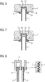
- FIG 6 shows a section of a power module unit 1. Shown is a section of the base plate 3 with the recess 9, a cooling fin 7 having been introduced into the recess 9.
- the cooling fin 7 comprises an attachment 25, the attachment 25 being positioned on the respective side of the cooling fin 7 such that a cavity 23 is formed in the recess after the cooling fin 7 has been introduced into the recess 9 is.
- the cavity 23 is arranged between the side of the cooling fin 7 and the bottom side of the recess 9.
- the cavity 23 is formed because the cooling fin is not completely inserted into the recess 9.
- the respective attachment 25 is positioned on the sides of the cooling fin 7 in such a way that the attachment 25 touches or is fastened to the first side 31 after the cooling fin 7 has been introduced into the recess 9.
- the attachment 25 of the cooling fin 7 advantageously lies on the first side 3a of the base plate 3.
- the bearing of the attachment 25 on the first side 3a advantageously increases a flat connection 21 between the cooling fin 7 and the base plate.
- the flat connection serves to transfer heat from the base plate 3 to the cooling fin.
- the height of the cavity 23 can also be made so small that the underside of the recess 9 touches the cooling fin 7 in places.
- FIG 7 shows a section of a power module unit 1. Analogous to the section shown in FIG 6 is shown, the cooling fin 7 also has an attachment 25.
- the attachment 25 is designed such that it has an inclined contact surface, the inclined contact surface resting on a corresponding incline in the recess 9.
- the forces which arise are identified by arrows.
- the forces symbolized by the arrows
- the forces have a force component in a direction parallel to the first side of the base plate 3.
- the cooling fin 7 Due to the oblique orientation of the support surface, less force is applied to the base plate 3 when the cooling fin 7 is introduced to form a bending stress and thus to stress the substrate 4.
- the area between the cooling fin 7 and the base plate 3 is enlarged. Due to the enlarged area, heat can be emitted from the base plate 3 onto the cooling fin.
- the inside 9a of the recess 9 and / or the cooling fin 7 has an embossment 10 on its side.
- the embossment preferably protrudes into a notch, the notch being introduced on the side which touches the embossment.
- Such an embossing 10 preferably contributes to the improved stability of the connection between the base plate 3 and the cooling fin 7.
- FIG 8 shows a connection 21 between cooling fins 7 and further cooling fins 7 '.
- the connection 21 between the cooling fins 7 and the further cooling fins 7 ' can be formed by a clamp connection or a non-positive connection.
- the cooling fins 7 and / or the further cooling fins 7 ′ can have a ribbed structure in the region of the connection 21.
- Cooling fins 7 and / or further cooling fins 7 ′ preferably have, on their respective sides, areas with parallel impressions with a triangular cross section. These impressions can also protrude into notches, the notches having a triangular cross section and being positioned between the impressions in the cooling fin 7 and / or the further cooling fin 7 '.
- Such a connection 21 is shown in the enlarged view.
- the ribbed structure serves for a more stable connection of the cooling fins 7 to the respective further cooling fin 7 '.
- a connecting element 17 is shown, the connecting element 17 providing the possibility of connecting the cooling fins 7 (analogous to the embodiment shown in FIG 5 is shown) disclosed.
- the further cooling fins 7 ′ which are introduced in the interspaces of the cooling fins 7 aligned in parallel, each serve to further improve the cooling parallel cooling fins 7 and thus for improved cooling of the substrate 4 on the base plate 3.
- the invention relates to a method for producing a power module unit 1 and a power module unit 1. Furthermore, the invention relates to a power supply unit and a frequency converter.
- a base plate 3 is provided with cutouts 9. The base plate is connected to a substrate 4, which carries the power semiconductor 5. After the substrate 4 has been fastened to the base plate, the cooling fins 7 are guided into the cutouts 9 in the base plate 3 and fastened in a form-fitting and / or non-positive manner.
- a power module unit 1 can be formed with cooling fins 7 as required and at the same time the production of the power module unit 1 can be simplified.
Landscapes
- Engineering & Computer Science (AREA)
- Microelectronics & Electronic Packaging (AREA)
- Physics & Mathematics (AREA)
- Thermal Sciences (AREA)
- Cooling Or The Like Of Electrical Apparatus (AREA)
- Cooling Or The Like Of Semiconductors Or Solid State Devices (AREA)
- Chemical & Material Sciences (AREA)
- Materials Engineering (AREA)
Priority Applications (5)
| Application Number | Priority Date | Filing Date | Title |
|---|---|---|---|
| EP18194020.6A EP3624184A1 (fr) | 2018-09-12 | 2018-09-12 | Procédé de fabrication d'une unité de module de puissance, unité de module de puissance, bloc d'alimentation et convertisseur de fréquence |
| CN201980059484.8A CN112673469B (zh) | 2018-09-12 | 2019-07-03 | 制造功率模块单元的方法、功率模块单元、电源部件和变频器 |
| EP19739950.4A EP3818562B1 (fr) | 2018-09-12 | 2019-07-03 | Procédé de fabrication d'une unité de module de puissance, unité de module de puissance, bloc d'alimentation et convertisseur de fréquence |
| PCT/EP2019/067881 WO2020052829A1 (fr) | 2018-09-12 | 2019-07-03 | Procédé de fabrication d'une unité de module de puissance, unité de module de puissance, alimentation électrique et convertisseur de fréquence |
| US17/275,621 US20220059426A1 (en) | 2018-09-12 | 2019-07-03 | Method for producing a power module unit, power module unit, network part and frequency converter |
Applications Claiming Priority (1)
| Application Number | Priority Date | Filing Date | Title |
|---|---|---|---|
| EP18194020.6A EP3624184A1 (fr) | 2018-09-12 | 2018-09-12 | Procédé de fabrication d'une unité de module de puissance, unité de module de puissance, bloc d'alimentation et convertisseur de fréquence |
Publications (1)
| Publication Number | Publication Date |
|---|---|
| EP3624184A1 true EP3624184A1 (fr) | 2020-03-18 |
Family
ID=63642527
Family Applications (2)
| Application Number | Title | Priority Date | Filing Date |
|---|---|---|---|
| EP18194020.6A Withdrawn EP3624184A1 (fr) | 2018-09-12 | 2018-09-12 | Procédé de fabrication d'une unité de module de puissance, unité de module de puissance, bloc d'alimentation et convertisseur de fréquence |
| EP19739950.4A Active EP3818562B1 (fr) | 2018-09-12 | 2019-07-03 | Procédé de fabrication d'une unité de module de puissance, unité de module de puissance, bloc d'alimentation et convertisseur de fréquence |
Family Applications After (1)
| Application Number | Title | Priority Date | Filing Date |
|---|---|---|---|
| EP19739950.4A Active EP3818562B1 (fr) | 2018-09-12 | 2019-07-03 | Procédé de fabrication d'une unité de module de puissance, unité de module de puissance, bloc d'alimentation et convertisseur de fréquence |
Country Status (4)
| Country | Link |
|---|---|
| US (1) | US20220059426A1 (fr) |
| EP (2) | EP3624184A1 (fr) |
| CN (1) | CN112673469B (fr) |
| WO (1) | WO2020052829A1 (fr) |
Cited By (3)
| Publication number | Priority date | Publication date | Assignee | Title |
|---|---|---|---|---|
| EP3933913A1 (fr) | 2020-06-30 | 2022-01-05 | Siemens Aktiengesellschaft | Module de puissance pourvu d'au moins deux unités de puissance |
| EP3961698A1 (fr) | 2020-08-26 | 2022-03-02 | Siemens Aktiengesellschaft | Module semi-conducteur doté d'un dissipateur thermique |
| EP4586306A1 (fr) * | 2024-01-12 | 2025-07-16 | Siemens Aktiengesellschaft | Dissipateur thermique pour dispositif semi-conducteur, module semi-conducteur, convertisseur de puissance et procédé de fabrication d'un tel dissipateur thermique |
Families Citing this family (5)
| Publication number | Priority date | Publication date | Assignee | Title |
|---|---|---|---|---|
| EP3955717B1 (fr) | 2020-08-14 | 2024-12-25 | Siemens Aktiengesellschaft | Convertisseur multi-niveau à topologie optimisée |
| DE102020133635B4 (de) | 2020-12-16 | 2024-09-12 | Audi Aktiengesellschaft | Verfahren zur Herstellung einer Elektronikbaugruppe, Elektronikbaugruppe und Kraftfahrzeug |
| JP7800168B2 (ja) * | 2022-01-31 | 2026-01-16 | 日本軽金属株式会社 | ヒートシンク |
| DE102023107033B3 (de) * | 2023-03-21 | 2024-06-13 | Danfoss Silicon Power Gmbh | Drucksinterverfahren unter Einsatz eines Verformungsaufnahmemittels und damit hergestellte Baugruppe |
| CN117766470B (zh) * | 2024-02-20 | 2024-05-14 | 北京怀柔实验室 | 半导体器件的封装结构和封装方法 |
Citations (6)
| Publication number | Priority date | Publication date | Assignee | Title |
|---|---|---|---|---|
| EP1378940A2 (fr) * | 2002-07-01 | 2004-01-07 | Alcan Technology & Management AG | Refroidisseur pour éléments semiconducteurs ou dispositifs similaires |
| EP2031332A1 (fr) * | 2007-08-27 | 2009-03-04 | ABB Research LTD | Échangeur de chaleur |
| EP2328172A1 (fr) * | 2009-10-02 | 2011-06-01 | Abb Research Ltd. | Agencement électronique de puissance |
| US20120112201A1 (en) * | 2010-11-09 | 2012-05-10 | Board of Trustees of the Univ. of Arkansas, acting for&on behalf of the Univ. of Arkansas,Fayetevill | High melting point soldering layer and fabrication method for the same, and semiconductor device |
| DE102013207804A1 (de) | 2012-04-30 | 2013-10-31 | Infineon Technologies Ag | Leistungsmodul mit direkt verbundenen, wärmeleitenden strukturen |
| EP3190371A1 (fr) * | 2016-01-07 | 2017-07-12 | ABB Schweiz AG | Échangeur de chaleur pour composants électroniques |
Family Cites Families (11)
| Publication number | Priority date | Publication date | Assignee | Title |
|---|---|---|---|---|
| DE3518310A1 (de) * | 1985-05-22 | 1986-11-27 | Aluminium-Walzwerke Singen Gmbh, 7700 Singen | Kuehlkoerper fuer halbleiterbauelemente und verfahren zu seiner herstellung |
| DE29715585U1 (de) * | 1997-08-28 | 1998-12-24 | Hoogovens Aluminium Profiltechnik Bonn GmbH, 53117 Bonn | Kühlvorrichtung für elektrische bzw. elektronische Bauelemente |
| US6520248B2 (en) * | 2000-05-18 | 2003-02-18 | Aavid Thermalloy Llc | Heat sink having bonded cooling fins |
| DE10157240B4 (de) * | 2001-11-22 | 2012-10-25 | Aleris Aluminum Vogt Gmbh | Kühlkörper und Verfahren zur Herstellung desselben |
| US8499824B2 (en) * | 2005-10-04 | 2013-08-06 | Elektronische Bauelemente Gesellschaft M.B.H. | Heat sink |
| DE102006038980B4 (de) * | 2006-08-21 | 2009-02-19 | Alcan Technology & Management Ag | Kühlkörper für Halbleiterbauelemente sowie Verfahren zu seiner Herstellung |
| CN101394729B (zh) * | 2007-09-19 | 2011-12-14 | 鸿富锦精密工业(深圳)有限公司 | 散热器及其制造方法 |
| EP2272311B1 (fr) * | 2008-05-02 | 2016-10-26 | Danfoss Silicon Power GmbH | Dispositif de refroidissement pour une pluralité de modules de puissance |
| CN101711104B (zh) * | 2009-05-12 | 2012-05-23 | 大连丽昌新材料有限公司 | 一种石墨散热装置 |
| WO2017057093A1 (fr) * | 2015-09-29 | 2017-04-06 | 三菱電機株式会社 | Dispositif à semi-conducteur et son procédé de fabrication |
| US11152280B2 (en) * | 2016-11-24 | 2021-10-19 | Mitsubishi Electric Corporation | Semiconductor device and method for manufacturing the same |
-
2018
- 2018-09-12 EP EP18194020.6A patent/EP3624184A1/fr not_active Withdrawn
-
2019
- 2019-07-03 US US17/275,621 patent/US20220059426A1/en not_active Abandoned
- 2019-07-03 EP EP19739950.4A patent/EP3818562B1/fr active Active
- 2019-07-03 WO PCT/EP2019/067881 patent/WO2020052829A1/fr not_active Ceased
- 2019-07-03 CN CN201980059484.8A patent/CN112673469B/zh active Active
Patent Citations (6)
| Publication number | Priority date | Publication date | Assignee | Title |
|---|---|---|---|---|
| EP1378940A2 (fr) * | 2002-07-01 | 2004-01-07 | Alcan Technology & Management AG | Refroidisseur pour éléments semiconducteurs ou dispositifs similaires |
| EP2031332A1 (fr) * | 2007-08-27 | 2009-03-04 | ABB Research LTD | Échangeur de chaleur |
| EP2328172A1 (fr) * | 2009-10-02 | 2011-06-01 | Abb Research Ltd. | Agencement électronique de puissance |
| US20120112201A1 (en) * | 2010-11-09 | 2012-05-10 | Board of Trustees of the Univ. of Arkansas, acting for&on behalf of the Univ. of Arkansas,Fayetevill | High melting point soldering layer and fabrication method for the same, and semiconductor device |
| DE102013207804A1 (de) | 2012-04-30 | 2013-10-31 | Infineon Technologies Ag | Leistungsmodul mit direkt verbundenen, wärmeleitenden strukturen |
| EP3190371A1 (fr) * | 2016-01-07 | 2017-07-12 | ABB Schweiz AG | Échangeur de chaleur pour composants électroniques |
Cited By (7)
| Publication number | Priority date | Publication date | Assignee | Title |
|---|---|---|---|---|
| EP3933913A1 (fr) | 2020-06-30 | 2022-01-05 | Siemens Aktiengesellschaft | Module de puissance pourvu d'au moins deux unités de puissance |
| WO2022002464A1 (fr) | 2020-06-30 | 2022-01-06 | Siemens Aktiengesellschaft | Module de puissance comprenant au moins trois unités de puissance |
| US12593729B2 (en) | 2020-06-30 | 2026-03-31 | Siemens Aktiengesellschaft | Power module having at least three power units |
| EP3961698A1 (fr) | 2020-08-26 | 2022-03-02 | Siemens Aktiengesellschaft | Module semi-conducteur doté d'un dissipateur thermique |
| WO2022042895A1 (fr) | 2020-08-26 | 2022-03-03 | Siemens Aktiengesellschaft | Module à semi-conducteur comprenant un dissipateur thermique |
| EP4586306A1 (fr) * | 2024-01-12 | 2025-07-16 | Siemens Aktiengesellschaft | Dissipateur thermique pour dispositif semi-conducteur, module semi-conducteur, convertisseur de puissance et procédé de fabrication d'un tel dissipateur thermique |
| WO2025149391A1 (fr) | 2024-01-12 | 2025-07-17 | Siemens Aktiengesellschaft | Dissipateur thermique pour ensemble à semi-conducteur, module à semi-conducteur, redresseur de courant et procédé de fabrication d'un dissipateur thermique de ce type |
Also Published As
| Publication number | Publication date |
|---|---|
| WO2020052829A1 (fr) | 2020-03-19 |
| CN112673469A (zh) | 2021-04-16 |
| EP3818562A1 (fr) | 2021-05-12 |
| EP3818562B1 (fr) | 2026-05-06 |
| US20220059426A1 (en) | 2022-02-24 |
| CN112673469B (zh) | 2025-12-05 |
Similar Documents
| Publication | Publication Date | Title |
|---|---|---|
| EP3818562B1 (fr) | Procédé de fabrication d'une unité de module de puissance, unité de module de puissance, bloc d'alimentation et convertisseur de fréquence | |
| EP4128337B1 (fr) | Module de puissance pourvu d'au moins trois unités de puissance | |
| DE102016014686B4 (de) | Thermoelektrische Einrichtung, Verfahren zu seiner Herstellung, Getränkehalter für ein Fahrzeug sowie Temperier-Vorrichtung für Sitze | |
| DE112014006676B4 (de) | Leistungsmodulvorrichtung | |
| DE102009001722A1 (de) | Verfahren zum Aufbringen eines Wärmeleitmediums auf eine Wärmeableitfläche | |
| EP3483930B1 (fr) | Unite electronique | |
| WO2009052814A2 (fr) | Dispositif de refroidissement pour composants à semi-conducteur, ensemble de refroidissement à semi-conducteur et leur procédé de fabrication | |
| DE112006004034T5 (de) | Wärmerohr-Kühlvorrichtung und Verfahren zu ihrer Herstellung | |
| DE102005045100A1 (de) | Verfahren zum Herstellen eines Leistungshalbleitermoduls | |
| WO2013068055A1 (fr) | Pièce moulée à encastrer dans une carte de circuits imprimés | |
| EP3345217B1 (fr) | Dispositif de refroidissement, procédé de fabrication d'un dispositif de refroidissement et circuit de puissance | |
| DE102024202012B3 (de) | Vorrichtung und Verfahren zum Fertigen einer Leistungshalbleiter-Baugruppe sowie eine derart hergestellte Leistungshalbleiter-Baugruppe | |
| DE102015204915B4 (de) | Wärmeleitkörper mit einer Koppeloberfläche mit Vertiefung und Wärmetransfervorrichtung | |
| DE102025120269B3 (de) | Sinterpresse für ein Hochvolt-Leistungsmodul, ein Sintermaterialdrucker für ein Hochvolt-Leistungsmodul, sowie ein Sinterverfahren für ein Hochvolt-Leistungsmodul | |
| DE102019115573B4 (de) | Leistungselektronische Schalteinrichtung und Verfahren zur Herstellung | |
| EP4080559A1 (fr) | Module semi-conducteur doté d'un substrat et d'au moins un composant semi-conducteur mis en contact sur le substrat | |
| DE102022130928B3 (de) | Verfahren zum Drucksintern, Unterwerkzeug für eine Sinterpresse und Sinterpresse mit einem solchen Unterwerkzeug | |
| EP3993025B1 (fr) | Composant de compensation | |
| DE10157240B4 (de) | Kühlkörper und Verfahren zur Herstellung desselben | |
| DE102015115133B3 (de) | Verfahren zum Verbinden eines Kühlkörpers mit wenigstens einem Schaltungsträger durch Aufschrumpfen | |
| EP3981229A1 (fr) | Procédé de fabrication d'un boîtier entourant un appareil de commande | |
| AT528012B1 (de) | Kühlvorrichtung | |
| DE102024205055A1 (de) | Vorrichtung zum kraftschlüssigen Verbinden eines Kühlkörpers mit einem Leistungsmodul | |
| EP4476762B1 (fr) | Procédé de fabrication d'un corps dissipateur à ailettes et d'une paroi latérale tournante | |
| DE102023117295A1 (de) | Anordnung sowie Verfahren zum Herstellen einer thermischen und mechanischen Verbindung zwischen einer Leiterplatte und einer Kühlvorrichtung sowie Leiterplatte und Steuereinheit |
Legal Events
| Date | Code | Title | Description |
|---|---|---|---|
| PUAI | Public reference made under article 153(3) epc to a published international application that has entered the european phase |
Free format text: ORIGINAL CODE: 0009012 |
|
| STAA | Information on the status of an ep patent application or granted ep patent |
Free format text: STATUS: THE APPLICATION HAS BEEN PUBLISHED |
|
| AK | Designated contracting states |
Kind code of ref document: A1 Designated state(s): AL AT BE BG CH CY CZ DE DK EE ES FI FR GB GR HR HU IE IS IT LI LT LU LV MC MK MT NL NO PL PT RO RS SE SI SK SM TR |
|
| AX | Request for extension of the european patent |
Extension state: BA ME |
|
| STAA | Information on the status of an ep patent application or granted ep patent |
Free format text: STATUS: THE APPLICATION IS DEEMED TO BE WITHDRAWN |
|
| 18D | Application deemed to be withdrawn |
Effective date: 20200919 |