EP3624276A1 - Connecteur - Google Patents
Connecteur Download PDFInfo
- Publication number
- EP3624276A1 EP3624276A1 EP18799119.5A EP18799119A EP3624276A1 EP 3624276 A1 EP3624276 A1 EP 3624276A1 EP 18799119 A EP18799119 A EP 18799119A EP 3624276 A1 EP3624276 A1 EP 3624276A1
- Authority
- EP
- European Patent Office
- Prior art keywords
- housing
- connector
- retainer
- base end
- end portion
- Prior art date
- Legal status (The legal status is an assumption and is not a legal conclusion. Google has not performed a legal analysis and makes no representation as to the accuracy of the status listed.)
- Withdrawn
Links
Images




Classifications
-
- H—ELECTRICITY
- H01—ELECTRIC ELEMENTS
- H01R—ELECTRICALLY-CONDUCTIVE CONNECTIONS; STRUCTURAL ASSOCIATIONS OF A PLURALITY OF MUTUALLY-INSULATED ELECTRICAL CONNECTING ELEMENTS; COUPLING DEVICES; CURRENT COLLECTORS
- H01R13/00—Details of coupling devices of the kinds covered by groups H01R12/70 or H01R24/00 - H01R33/00
- H01R13/40—Securing contact members in or to a base or case; Insulating of contact members
- H01R13/42—Securing in a demountable manner
- H01R13/422—Securing in resilient one-piece base or case, e.g. by friction; One-piece base or case formed with resilient locking means
- H01R13/4223—Securing in resilient one-piece base or case, e.g. by friction; One-piece base or case formed with resilient locking means comprising integral flexible contact retaining fingers
-
- H—ELECTRICITY
- H01—ELECTRIC ELEMENTS
- H01R—ELECTRICALLY-CONDUCTIVE CONNECTIONS; STRUCTURAL ASSOCIATIONS OF A PLURALITY OF MUTUALLY-INSULATED ELECTRICAL CONNECTING ELEMENTS; COUPLING DEVICES; CURRENT COLLECTORS
- H01R13/00—Details of coupling devices of the kinds covered by groups H01R12/70 or H01R24/00 - H01R33/00
- H01R13/40—Securing contact members in or to a base or case; Insulating of contact members
- H01R13/42—Securing in a demountable manner
- H01R13/436—Securing a plurality of contact members by one locking piece or operation
- H01R13/4361—Insertion of locking piece perpendicular to direction of contact insertion
-
- H—ELECTRICITY
- H01—ELECTRIC ELEMENTS
- H01R—ELECTRICALLY-CONDUCTIVE CONNECTIONS; STRUCTURAL ASSOCIATIONS OF A PLURALITY OF MUTUALLY-INSULATED ELECTRICAL CONNECTING ELEMENTS; COUPLING DEVICES; CURRENT COLLECTORS
- H01R12/00—Structural associations of a plurality of mutually-insulated electrical connecting elements, specially adapted for printed circuits, e.g. printed circuit boards [PCB], flat or ribbon cables, or like generally planar structures, e.g. terminal strips, terminal blocks; Coupling devices specially adapted for printed circuits, flat or ribbon cables, or like generally planar structures; Terminals specially adapted for contact with, or insertion into, printed circuits, flat or ribbon cables, or like generally planar structures
- H01R12/70—Coupling devices
- H01R12/77—Coupling devices for flexible printed circuits, flat or ribbon cables or like structures
- H01R12/771—Details
- H01R12/774—Retainers
-
- H—ELECTRICITY
- H01—ELECTRIC ELEMENTS
- H01R—ELECTRICALLY-CONDUCTIVE CONNECTIONS; STRUCTURAL ASSOCIATIONS OF A PLURALITY OF MUTUALLY-INSULATED ELECTRICAL CONNECTING ELEMENTS; COUPLING DEVICES; CURRENT COLLECTORS
- H01R13/00—Details of coupling devices of the kinds covered by groups H01R12/70 or H01R24/00 - H01R33/00
- H01R13/02—Contact members
- H01R13/10—Sockets for co-operation with pins or blades
- H01R13/11—Resilient sockets
- H01R13/112—Resilient sockets forked sockets having two legs
-
- H—ELECTRICITY
- H01—ELECTRIC ELEMENTS
- H01R—ELECTRICALLY-CONDUCTIVE CONNECTIONS; STRUCTURAL ASSOCIATIONS OF A PLURALITY OF MUTUALLY-INSULATED ELECTRICAL CONNECTING ELEMENTS; COUPLING DEVICES; CURRENT COLLECTORS
- H01R13/00—Details of coupling devices of the kinds covered by groups H01R12/70 or H01R24/00 - H01R33/00
- H01R13/40—Securing contact members in or to a base or case; Insulating of contact members
- H01R13/42—Securing in a demountable manner
- H01R13/436—Securing a plurality of contact members by one locking piece or operation
- H01R13/4361—Insertion of locking piece perpendicular to direction of contact insertion
- H01R13/4362—Insertion of locking piece perpendicular to direction of contact insertion comprising a temporary and a final locking position
-
- H—ELECTRICITY
- H01—ELECTRIC ELEMENTS
- H01R—ELECTRICALLY-CONDUCTIVE CONNECTIONS; STRUCTURAL ASSOCIATIONS OF A PLURALITY OF MUTUALLY-INSULATED ELECTRICAL CONNECTING ELEMENTS; COUPLING DEVICES; CURRENT COLLECTORS
- H01R13/00—Details of coupling devices of the kinds covered by groups H01R12/70 or H01R24/00 - H01R33/00
- H01R13/46—Bases; Cases
- H01R13/533—Bases, cases made for use in extreme conditions, e.g. high temperature, radiation, vibration, corrosive environment, pressure
-
- H—ELECTRICITY
- H01—ELECTRIC ELEMENTS
- H01R—ELECTRICALLY-CONDUCTIVE CONNECTIONS; STRUCTURAL ASSOCIATIONS OF A PLURALITY OF MUTUALLY-INSULATED ELECTRICAL CONNECTING ELEMENTS; COUPLING DEVICES; CURRENT COLLECTORS
- H01R13/00—Details of coupling devices of the kinds covered by groups H01R12/70 or H01R24/00 - H01R33/00
- H01R13/62—Means for facilitating engagement or disengagement of coupling parts or for holding them in engagement
- H01R13/629—Additional means for facilitating engagement or disengagement of coupling parts, e.g. aligning or guiding means, levers, gas pressure electrical locking indicators, manufacturing tolerances
- H01R13/631—Additional means for facilitating engagement or disengagement of coupling parts, e.g. aligning or guiding means, levers, gas pressure electrical locking indicators, manufacturing tolerances for engagement only
- H01R13/6315—Additional means for facilitating engagement or disengagement of coupling parts, e.g. aligning or guiding means, levers, gas pressure electrical locking indicators, manufacturing tolerances for engagement only allowing relative movement between coupling parts, e.g. floating connection
-
- H—ELECTRICITY
- H01—ELECTRIC ELEMENTS
- H01R—ELECTRICALLY-CONDUCTIVE CONNECTIONS; STRUCTURAL ASSOCIATIONS OF A PLURALITY OF MUTUALLY-INSULATED ELECTRICAL CONNECTING ELEMENTS; COUPLING DEVICES; CURRENT COLLECTORS
- H01R11/00—Individual connecting elements providing two or more spaced connecting locations for conductive members which are, or may be, thereby interconnected, e.g. end pieces for wires or cables supported by the wire or cable and having means for facilitating electrical connection to some other wire, terminal, or conductive member, blocks of binding posts
- H01R11/03—Individual connecting elements providing two or more spaced connecting locations for conductive members which are, or may be, thereby interconnected, e.g. end pieces for wires or cables supported by the wire or cable and having means for facilitating electrical connection to some other wire, terminal, or conductive member, blocks of binding posts characterised by the relationship between the connecting locations
- H01R11/05—Individual connecting elements providing two or more spaced connecting locations for conductive members which are, or may be, thereby interconnected, e.g. end pieces for wires or cables supported by the wire or cable and having means for facilitating electrical connection to some other wire, terminal, or conductive member, blocks of binding posts characterised by the relationship between the connecting locations the connecting locations having different types of direct connections
-
- H—ELECTRICITY
- H01—ELECTRIC ELEMENTS
- H01R—ELECTRICALLY-CONDUCTIVE CONNECTIONS; STRUCTURAL ASSOCIATIONS OF A PLURALITY OF MUTUALLY-INSULATED ELECTRICAL CONNECTING ELEMENTS; COUPLING DEVICES; CURRENT COLLECTORS
- H01R12/00—Structural associations of a plurality of mutually-insulated electrical connecting elements, specially adapted for printed circuits, e.g. printed circuit boards [PCB], flat or ribbon cables, or like generally planar structures, e.g. terminal strips, terminal blocks; Coupling devices specially adapted for printed circuits, flat or ribbon cables, or like generally planar structures; Terminals specially adapted for contact with, or insertion into, printed circuits, flat or ribbon cables, or like generally planar structures
- H01R12/70—Coupling devices
- H01R12/77—Coupling devices for flexible printed circuits, flat or ribbon cables or like structures
- H01R12/778—Coupling parts carrying sockets, clips or analogous counter-contacts
-
- H—ELECTRICITY
- H01—ELECTRIC ELEMENTS
- H01R—ELECTRICALLY-CONDUCTIVE CONNECTIONS; STRUCTURAL ASSOCIATIONS OF A PLURALITY OF MUTUALLY-INSULATED ELECTRICAL CONNECTING ELEMENTS; COUPLING DEVICES; CURRENT COLLECTORS
- H01R13/00—Details of coupling devices of the kinds covered by groups H01R12/70 or H01R24/00 - H01R33/00
- H01R13/02—Contact members
- H01R13/22—Contacts for co-operating by abutting
- H01R13/24—Contacts for co-operating by abutting resilient; resiliently-mounted
- H01R13/2407—Contacts for co-operating by abutting resilient; resiliently-mounted characterized by the resilient means
- H01R13/2428—Contacts for co-operating by abutting resilient; resiliently-mounted characterized by the resilient means using meander springs
-
- H—ELECTRICITY
- H01—ELECTRIC ELEMENTS
- H01R—ELECTRICALLY-CONDUCTIVE CONNECTIONS; STRUCTURAL ASSOCIATIONS OF A PLURALITY OF MUTUALLY-INSULATED ELECTRICAL CONNECTING ELEMENTS; COUPLING DEVICES; CURRENT COLLECTORS
- H01R13/00—Details of coupling devices of the kinds covered by groups H01R12/70 or H01R24/00 - H01R33/00
- H01R13/40—Securing contact members in or to a base or case; Insulating of contact members
- H01R13/42—Securing in a demountable manner
- H01R13/428—Securing in a demountable manner by resilient locking means on the contact members; by locking means on resilient contact members
- H01R13/432—Securing in a demountable manner by resilient locking means on the contact members; by locking means on resilient contact members by stamped-out resilient tongue snapping behind shoulder in base or case
-
- H—ELECTRICITY
- H01—ELECTRIC ELEMENTS
- H01R—ELECTRICALLY-CONDUCTIVE CONNECTIONS; STRUCTURAL ASSOCIATIONS OF A PLURALITY OF MUTUALLY-INSULATED ELECTRICAL CONNECTING ELEMENTS; COUPLING DEVICES; CURRENT COLLECTORS
- H01R2201/00—Connectors or connections adapted for particular applications
- H01R2201/26—Connectors or connections adapted for particular applications for vehicles
-
- H—ELECTRICITY
- H01—ELECTRIC ELEMENTS
- H01R—ELECTRICALLY-CONDUCTIVE CONNECTIONS; STRUCTURAL ASSOCIATIONS OF A PLURALITY OF MUTUALLY-INSULATED ELECTRICAL CONNECTING ELEMENTS; COUPLING DEVICES; CURRENT COLLECTORS
- H01R4/00—Electrically-conductive connections between two or more conductive members in direct contact, i.e. touching one another; Means for effecting or maintaining such contact; Electrically-conductive connections having two or more spaced connecting locations for conductors and using contact members penetrating insulation
- H01R4/10—Electrically-conductive connections between two or more conductive members in direct contact, i.e. touching one another; Means for effecting or maintaining such contact; Electrically-conductive connections having two or more spaced connecting locations for conductors and using contact members penetrating insulation effected solely by twisting, wrapping, bending, crimping, or other permanent deformation
- H01R4/18—Electrically-conductive connections between two or more conductive members in direct contact, i.e. touching one another; Means for effecting or maintaining such contact; Electrically-conductive connections having two or more spaced connecting locations for conductors and using contact members penetrating insulation effected solely by twisting, wrapping, bending, crimping, or other permanent deformation by crimping
- H01R4/183—Electrically-conductive connections between two or more conductive members in direct contact, i.e. touching one another; Means for effecting or maintaining such contact; Electrically-conductive connections having two or more spaced connecting locations for conductors and using contact members penetrating insulation effected solely by twisting, wrapping, bending, crimping, or other permanent deformation by crimping for cylindrical elongated bodies, e.g. cables having circular cross-section
- H01R4/184—Electrically-conductive connections between two or more conductive members in direct contact, i.e. touching one another; Means for effecting or maintaining such contact; Electrically-conductive connections having two or more spaced connecting locations for conductors and using contact members penetrating insulation effected solely by twisting, wrapping, bending, crimping, or other permanent deformation by crimping for cylindrical elongated bodies, e.g. cables having circular cross-section comprising a U-shaped wire-receiving portion
- H01R4/185—Electrically-conductive connections between two or more conductive members in direct contact, i.e. touching one another; Means for effecting or maintaining such contact; Electrically-conductive connections having two or more spaced connecting locations for conductors and using contact members penetrating insulation effected solely by twisting, wrapping, bending, crimping, or other permanent deformation by crimping for cylindrical elongated bodies, e.g. cables having circular cross-section comprising a U-shaped wire-receiving portion combined with a U-shaped insulation-receiving portion
Definitions
- the present invention relates to a connector.
- the connector disclosed in Patent Document 1 includes a housing, a press-contact terminal that is accommodated in the housing and of which one end (terminal) is connected to a connection target and another end (barrel) forms a press-contact connection with an electric cable, and a retainer that is fitted into the housing. Fitting the retainer into the housing prevents the press-contact terminal connected to the electric cable from detaching inside the housing.
- This connector exploits the flexibility of the electric cable during an operation to connect the connector and the connection target together such that the connector can be manipulated relatively freely, and is thus easy to work with.
- Patent Document 1 Japanese Patent Application Laid-Open ( JP-A) No. 2014-186934
- the press-contact terminal accommodated in the housing might be tugged or pushed in by the electric cable. If this occurs, a contact point with the connection target at the one end (terminal) of the press-contact terminal might slide.
- the target for connection to the other end of the terminal may be a flexible printed circuit (FPC: flexible printed circuit board or flexible printed wiring board) or a flexible flat cable (FFC) instead of an electric cable (namely, the connector may be configured as an FPC connector or an FFC connector).
- FPCs and FFCs have similar flexibility to an electric cable, and are able to flex. In such cases, similarly to in the case of an electric cable, such flexing may be transmitted to the terminal and cause sliding of the contact point.
- an object of the present invention is to provide a connector capable of suppressing sliding of a contact point when a flexible wiring member (electric cable, FPC, FFC, or the like) flexes as a result of a vibration or shock.
- a connector includes a terminal configured to electrically connect to an insertable and removable connection target, a housing configured to accommodate the terminal, and a retainer configured to fit into the housing in which the terminal is accommodated.
- the terminal includes a base end portion provided with a flexible wiring member connection portion configured to connect to a flexible wiring member, a leading end portion provided with a contact portion configured to contact the connection target, and a spring portion positioned between the base end portion and the leading end portion.
- the leading end portion is prevented from detaching either by the housing, or by the housing and the retainer working in combination, and when the retainer is in a state fitted to the housing, the base end portion is capable of moving with respect to the housing within a predetermined movable region in a connector front-rear direction that is an insertion/removal direction of the connection target.
- the connector includes the terminal, the housing, and the retainer.
- the retainer is fitted into the housing in which the terminal is accommodated.
- the terminal includes the leading end portion provided with the contact portion configured to contact the connection target. The leading end portion is either prevented from detaching by the housing and the retainer working in combination, or is prevented from detaching by the housing (for example by being press-fitted into the housing).
- the base end portion is capable of moving with respect to the housing in the connector front-rear direction, this being the insertion/removal direction of the connection target.
- the terminal further includes the spring portion positioned between the base end portion and the leading end portion.
- the base end portion provided with the flexible wiring member connection portion moves in the connector front-rear direction with respect to the housing, thereby enabling the effect of the flexing on the housing to be suppressed.
- the flexing can be suppressed from affecting the leading end portion through the housing.
- the spring portion positioned between the leading end portion and the base end portion deforms in response to this flexing, thereby enabling the effect of the flexing on the leading end portion provided with the contact portion to be suppressed.
- a connector according to a second aspect is the connector of the first aspect, wherein the housing includes a leading end placement portion at which the leading end portion can be disposed, the leading end placement portion includes a leading end-forward restriction portion configured to limit a movement range of the leading end portion in a connector forward direction that is a removal direction of the connection target, and the retainer includes a leading end-rearward restriction portion configured to, when the retainer is in a state fitted to the housing, limit a movement range of the leading end portion in a connector rearward direction that is an insertion direction of the connection target.
- the housing includes the leading end placement portion at which the leading end portion can be disposed.
- the leading end placement portion includes the leading end-forward restriction portion configured to limit the movement range of the leading end portion in the connector forward direction.
- the retainer includes the leading end-rearward restriction portion configured to limit the movement range of the leading end portion in the connector rearward direction when the retainer is in a state fitted to the housing.
- the terminal when accommodating the terminal in the housing, the terminal can be provisionally positioned with respect to the housing by pushing in the terminal until the leading end portion of the terminal abuts the leading end-forward restriction portion of the leading end placement portion. Detachment of the leading end portion of the terminal is then prevented by fitting the retainer into the housing. This enables easy assembly.
- a connector according to a third aspect is the connector of the first aspect or the second aspect, wherein the housing includes a bottom portion configured to restrict movement of the base end portion in a fitting direction of the retainer, and an abutting portion configured to restrict a movement range of the base end portion in a fitting-opposite direction that is the opposite direction from the fitting direction of the retainer.
- the housing includes the bottom portion configured to restrict movement of the base end portion in the fitting direction of the retainer, and the abutting portion configured to restrict the movement range of the base end portion in the fitting-opposite direction, this being the opposite direction from the fitting direction of the retainer. Accordingly, in a state in which the terminal is accommodated in the housing but the retainer has not yet been fitted into the housing, the base end portion is prevented from moving by a large amount in the fitting direction or the fitting-opposite direction. This enables the connector to be assembled easily.
- a connector according to a fourth aspect is the connector of the third aspect, wherein a movement clearance permitting movement of the base end portion in a connector up-down direction that is a fitting direction/fitting-opposite direction of the retainer is present between the base end portion and the bottom portion and between the base end portion and the abutting portion, and the base end portion is movable within a predetermined movement range in the connector up-down direction when the retainer is in a fitted state to the housing.
- the movement clearance that permits movement of the base end portion in the connector up-down direction is present between the base end portion and the bottom portion and between the base end portion and the abutting portion.
- the base end portion In a state in which the retainer has been fitted into the housing, the base end portion is movable within a predetermined movement range in the connector up-down direction.
- the flexible wiring member flexes so as to move the terminal in the connector up-down direction, the effect of the flexing on the housing and the retainer can be reduced. As a result, the flexing can be suppressed from affecting the leading end portion through the housing and the retainer.
- the spring portion positioned between the leading end portion and the base end portion deforms in response to this flexing, thereby enabling the effect of the flexing on the leading end portion provided with the contact portion to be reduced.
- the movement range of the base end portion in the connector up-down direction is limited to a predetermined range, thereby suppressing plastic deformation of the spring portion.
- a connector according to a fifth aspect is the connector of any one of the first aspect to the fourth aspect, wherein the base end portion is accommodated in a state in which a gap between the base end portion and the housing is present in a connector width direction that is a direction perpendicular both to an insertion direction of the connection target and to a fitting direction of the retainer, and the base end portion is movable in the connector width direction over a range of the gap when the retainer is in a fitted state to the housing.
- the base end portion is accommodated in a state in which a gap is present between the base end portion and the housing in the connector width direction, this being a direction perpendicular to both the insertion direction of the connection target and the fitting direction of the retainer.
- the base end portion In the fitted state of the retainer to the housing, the base end portion is movable in the connector width direction over the range of the gap. Namely, in the fitted state of the retainer to the housing, the retainer is movable within a predetermined movement range in a connector left-right direction.
- the flexible wiring member flexes so as to move the terminal in the connector left-right direction, the effect of the flexing on the housing and the retainer can be reduced. As a result, the flexing can be suppressed from affecting the leading end portion through the housing and the retainer.
- the spring portion positioned between the leading end portion and the base end portion deforms in response to this flexing, thereby enabling the effect of the flexing on the leading end portion provided with the contact portion to be reduced.
- the movement range of the base end portion in the connector left-right direction is limited to a predetermined range, thereby suppressing plastic deformation of the spring portion.
- a connector according to a sixth aspect is the connector of any one of the first aspect to the fifth aspect, wherein an insertion-removal axis of the contact portion is substantially parallel to a connection axis of the flexible wiring member connection portion, and is at a position that is offset with respect to the connection axis of the flexible wiring member connection portion in a fitting direction of the retainer.
- the insertion-removal axis of the contact portion is substantially parallel to the connection axis of the flexible wiring member connection portion, and is at a position that is offset with respect to the connection axis of the flexible wiring member connection portion in the fitting direction of the retainer. Accordingly, the ease of deformation of the spring portion can be secured while suppressing an increase in a front-rear direction dimension of the connector, while still effectively suppressing sliding of the contact point.
- a connector according to a seventh aspect is the connector of the sixth aspect, wherein the spring portion includes a doubling-back portion that doubles back in a connector rearward direction that is an insertion direction of the connection target.
- the spring portion extending from the base end portion to the leading end portion includes the doubling-back portion that doubles back in the connector rearward direction. This enables even easier deformation of the spring portion to be secured, while even more effectively suppressing sliding of the contact point.
- the present invention exhibits the excellent advantageous effect of being able to suppress sliding of a contact point even if an electric cable flexes as a result of vibration or shock.
- the connector 10 of the present exemplary embodiment includes plural (six) terminals 20, a housing 60, and a retainer 70.
- the connector 10 is assembled by first accommodating the terminals 20 in the housing 60, and then fitting the retainer 70 into the housing 60 in which the terminals 20 are accommodated (see Fig. 2 ).
- the six terminals 20 are configured similarly to each other.
- One of the six terminals 20 is illustrated in Fig. 4 and Fig. 5 . Explanation follows regarding this terminal 20 with reference to Fig. 4 and Fig. 5 .
- the arrow X, the arrow Y, and the arrow Z illustrated in Fig. 4 and Fig. 5 respectively indicate a terminal forward direction, one side (a left direction) in a terminal width direction, and a terminal upward direction.
- reference to the front and rear, up and down, and width (left and right) is understood to refer to the front and rear in a terminal front-rear direction, upward and downward in a terminal up-down direction, and width (left and right) in the terminal width direction (left-right direction).
- the front, rear, left, right, upward, and downward directions of the six terminals 20 are substantially aligned with the front, rear, left, right, upward, and downward directions of the connector 10.
- the terminals 20 are, for example, formed by punching and then bending a sheet material.
- the material employed for the terminals 20 is a material with electrically conductive properties, such as a copper alloy.
- the terminal 20 includes a base end portion 30 configuring one end side of the terminal 20, a leading end portion 50 configuring the other end side of the terminal 20, and a spring portion 40 positioned between the leading end portion 50 and the base end portion 30.
- the entire base end portion 30 is bent upward (toward a plate thickness direction inner face side) at both width direction sides.
- a cross-section profile of the base end portion 30 as sectioned orthogonally to the front-rear direction has an upward-opening U-shape or C-shape.
- the base end portion 30 extends toward the front from a rear end 20B of the terminal 20.
- the base end portion 30 includes an electric cable connection portion 31 and a base end side restricted portion 32 in this sequence on progression from the one end side toward the other end side.
- the electric cable connection portion 31 is a portion for connection to an electric cable 80 serving as a flexible wiring member, and corresponds to a flexible wiring member connection portion of the present invention.
- the electric cable connection portion 31 includes a sleeve press portion 31A that is pressed against a sleeve 84 of the electric cable 80 (see Fig. 1 ), and a core press portion 31B that is pressed against a core 82 (see Fig. 3 ) of the electric cable 80.
- the base end side restricted portion 32 is a portion configured to abut the housing 60 and the retainer 70 in order to limit a movement range of the base end portion 30.
- the base end side restricted portion 32 has an upward-opening U-shaped cross-section profile as sectioned orthogonally to the terminal front-rear direction. Namely, the base end side restricted portion 32 includes a bottom plate portion 33 extending in the width direction, a right side plate portion 34 extending upward from a right side end portion of the bottom plate portion 33, and a left side plate portion 34 extending upward from a left side end portion of the bottom plate portion 33.
- the right side plate portion 34 and the left side plate portion 34 of the base end side restricted portion 32 are also collectively referred to as the pair of side plate portions 34 of the base end side restricted portion 32.
- Each of the side plate portions 34 includes a front-facing front face 34F, an upward-facing upper face 34U, and a rear-facing rear face 34R. Tapered faces 35 facing in an oblique direction running upward and toward the front are formed between the front faces 34F and the upper faces 34U.
- the bottom plate portion 33 of the base end side restricted portion 32 is formed with a lance 36.
- the lance 36 is formed by bending a width direction central portion of the bottom plate portion 33 downward (toward a plate thickness direction outer face side).
- the spring portion 40 includes a first linear portion 41, an inclined portion 42, a first bent portion 43, a second linear portion 44, and a second bent portion 45 in this sequence on progression from the one end side toward the other end side.
- the spring portion 40 has a substantially uniform width dimension from one end to the other end. This width dimension is smaller than a width dimension of the base end side restricted portion 32, and is more specifically a dimension of no greater than one third of the width dimension of the base end side restricted portion 32.
- the first linear portion 41 extends toward the front from a width direction central portion of the bottom plate portion 33 of the base end side restricted portion 32.
- the plate thickness direction of the first linear portion 41 is oriented in the up-down direction, and the first linear portion 41 extends in a straight line toward the front from the one end toward the other end.
- the extension direction of the first linear portion 41 is substantially parallel to the terminal front-rear direction.
- the other end side of the first linear portion 41 is joined to the inclined portion 42 through a kinked portion kinked slightly toward the plate thickness direction inner face side.
- the plate thickness direction of the inclined portion 42 is substantially oriented in the up-down direction, and the inclined portion 42 extends in a straight line from one end to the other end in a direction inclined slightly upward with respect to the forward direction (an oblique direction running upward and toward the front).
- An angle formed between the extension direction of the inclined portion 42 and the terminal front-rear direction is less than 45°, and is set to approximately 20° in the present exemplary embodiment.
- An extension direction other end side of the inclined portion 42 is joined to the first bent portion 43.
- the first bent portion 43 is bent toward the plate thickness direction inner face side, and has a curved profile protruding toward the front.
- the extension direction of the first bent portion 43 is transformed through approximately 160° between one end and the other end thereof.
- the extension direction other end side of the first bent portion 43 is joined to the second linear portion 44.
- the plate thickness direction of the second linear portion 44 is substantially oriented in the up-down direction, and the second linear portion 44 extends in a straight line toward the rear from one end to the other end.
- the extension direction of the second linear portion 44 is substantially parallel to the terminal front-rear direction.
- the extension direction other end side of the second linear portion 44 is joined to the second bent portion 45.
- the second bent portion 45 is bent toward the plate thickness direction outer face side, and has a rearward-protruding profile. Specifically, the second bent portion 45 is configured including two kinked portions 45C, each bent by approximately 90°. The extension direction of the second bent portion 45 is transformed through approximately 180° between one end and the other end thereof. The extension direction other end side of the second bent portion 45 is joined to a leading end side restricted portion 51 of the leading end portion 50.
- the leading end portion 50 includes the leading end side restricted portion 51 and a contact portion 52.
- the leading end side restricted portion 51 is a portion configured to abut the housing 60 and the retainer 70 in order to limit a movement range of the leading end portion 50.
- the contact portion 52 is a portion configured to contact a connection target 90.
- the leading end side restricted portion 51 has a substantially rectangular shaped cross-section profile as sectioned orthogonally to the front-rear direction. Specifically, the leading end side restricted portion 51 is configured by a lower plate portion 51B, a right plate portion 51R extending upward from a right side end portion of the lower plate portion 51B, an upper plate portion 5 IT extending toward the left side from an upper end of the right plate portion 51R, and a left plate portion 51L extending downward from a left side end portion of the upper plate portion 51T. A width direction central portion of a rear end of the lower plate portion 51B is joined to the spring portion 40.
- the contact portion 52 includes a pair of contact tabs 52A.
- Each of the pair of contact tabs 52A extends toward the front from a width direction central portion of a front end of either the upper plate portion 51T or the lower plate portion 51B of the leading end side restricted portion 51 of the leading end portion 50.
- the pair of contact tabs 52A are configured to form an electrical connection with the connection target 90 by forming a contact with the connection target 90 in the up-down direction.
- the housing 60 is formed in a substantially rectangular block shape from an insulating body configured by a synthetic resin or the like.
- the housing 60, the arrow X, the arrow Y, and the arrow Z respectively indicate a housing forward direction, one side (a left side) in a housing width direction, and a housing upward direction.
- reference to the front and rear, up and down, and width (left and right) is understood to refer to the front and rear in a housing front-rear direction, up and down in a housing up-down direction, and width (left and right) in the housing width (left-right) direction.
- the front-rear, left-right, and up-down directions of the housing 60 are aligned with the front-rear, left-right, and up-down directions of the connector 10.
- the housing 60 includes accommodation portions 61 configured to accommodate the terminals 20.
- Each of the accommodation portions 61 is formed by a space extending along the front-rear direction within the housing 60.
- Plural of the accommodation portions 61 are formed (six in the present exemplary embodiment so as to correspond to the number of the terminals 20).
- the six accommodation portions 61 are configured similarly to each other, and are formed at uniform spacings in the housing width direction.
- Fig. 6 is a cross-section sectioned along a plane perpendicular to the housing left-right direction at a width direction central portion of the accommodation portion 61 furthest to the left side out of the six accommodation portions 61.
- the terminal 20 corresponding to the accommodation portion 61 furthest to the left side is omitted from illustration, whereas the other accommodation portions 61 are illustrated in a state in which the respective terminals 20 are accommodated therein.
- a rear face 60R of the housing 60 is formed with terminal push-in openings 61R.
- the terminal push-in openings 61R are in communication with the corresponding accommodation portions 61.
- the terminals 20 are pushed into the accommodation portions 61 through the terminal push-in openings 61R in order to accommodate the terminals 20 in the respective accommodation portions 61.
- the terminals 20 can be accommodated in the accommodation portions 61 by pushing the terminals 20 in toward the front through the terminal push-in openings 61R in the rear face 60R of the housing 60 in a state in which the front-rear and left-right directions of the terminal 20 are aligned with the front-rear and left-right directions of the housing 60, as illustrated in Fig. 1 .
- a front-rear direction intermediate portion 60B (housing intermediate portion 60B) of the housing 60 is formed with a substantially rectangular shaped retainer-fitting opening 60BH that opens upward from the housing.
- the retainer-fitting opening 60BH is in communication with the six accommodation portions 61. Atop face 61T of the accommodation portions 61 is therefore not present at the housing intermediate portion 60B.
- the plural accommodation portions 61 are separated from each other in a rear portion 60C (housing rear portion 60C) of the housing 60. Namely, in the housing rear portion 60C, a pair of left and right side wall faces 61S are formed spanning from a bottom face 61B to a top face 61T for each of the accommodation portions 61.
- the electric cable connection portion 31 of the base end portion 30 of the corresponding terminal 20 and the corresponding electric cable 80 are disposed between each pair of left and right side wall faces 61S in the housing rear portion 60C.
- the pairs of left and right side wall faces 61S are formed lower than the side wall faces 61S in the housing rear portion 60C.
- the height of the side wall faces 61S of the housing intermediate portion 60B corresponds to a position lower than the top face 61T of the housing rear portion 60C.
- the side wall faces 61S in the housing intermediate portion 60B are interrupted at a front-rear direction intermediate position of the housing intermediate portion 60B. Namely, if the housing intermediate portion 60B is further divided into a front side and a rear side, the side wall faces 61S are formed at the rear side of the housing intermediate portion 60B, but the side wall faces 61S are not formed at the front side of the housing intermediate portion 60B.
- the base end side restricted portion 32 of the terminal 20 is disposed between the left and right pair of the side wall faces 61S in the housing intermediate portion 60B (within the accommodation portion 61 in the housing intermediate portion 60B).
- the plural accommodation portions 61 are separated from each other in a front portion 60A (housing front portion 60A) of the housing 60. Namely, in the housing front portion 60A, a pair of left and right side wall faces 61S are formed spanning from the bottom face 61B to the top face 61T for each of the accommodation portions 61.
- the height of the top face 61T at the housing rear portion 60C is the same as the height of the top face 61T at the housing front portion 60A.
- part of the spring portion 40 (for example the first bent portion 43) and the leading end portion 50 of the corresponding terminal 20 are disposed between the left and right pair of the side wall faces 61S in the housing front portion 60A (inside the accommodation portion 61 in the housing front portion 60A).
- a spacing between each left and right pair of the side wall faces 61S (a width dimension of the accommodation portion 61) is formed so as to be larger than the width dimensions of the leading end side restricted portion 51 and the base end side restricted portion 32 of the corresponding terminal 20. Accordingly, when the terminal 20 is pushed into the accommodation portion 61, the leading end side restricted portion 51 and the base end side restricted portion 32 are capable of passing between the pair of left and right side wall faces 61S of the housing rear portion 60C in the front-rear direction. Accordingly, in a state in which the terminal 20 is accommodated in the corresponding accommodation portion 61, the base end side restricted portion 32 is capable of being disposed between the pair of left and right side wall faces 61S in the housing intermediate portion 60B.
- the spacing between each left and right pair of the side wall faces 61S is formed so as to be smaller than the width dimension of the leading end side restricted portion 51.
- recesses 62 are formed to increase the spacing between each left and right pair of the side wall faces 61S.
- One of the recesses 62 is formed to each of the left and right pair of side wall faces 61S such that each of the accommodation portions 61 is formed with a left and right pair of the recesses 62.
- each left and right pair of the recesses 62 is formed so as to be the same as or larger than the width dimension of the leading end side restricted portion 51 of the terminal 20.
- An up-down dimension of each of the recesses 62 is formed so as to be the same as or larger than an up-down dimension of the leading end side restricted portion 51.
- a front-rear dimension of each of the recesses 62 is formed so as to be the same as or larger than a front-rear dimension of the leading end side restricted portion 51. Accordingly, in a state in which the leading end side restricted portion 51 has been pushed into the recesses 62 toward the front, the leading end side restricted portion 51 does not project out into the housing intermediate portion 60B (the portion formed with the retainer-fitting opening 60BH).
- an upper portion of the accommodation portion 61 in the housing front portion 60A configures a leading end placement portion (an upper portion of the accommodation portion 61 in the housing front portion 60A) in which the leading end portion 50 of the terminal 20 is disposed, and a lower portion of the accommodation portion 61 in the housing front portion 60A configures a spring placement portion (a lower portion of the accommodation portion 61 in the housing front portion 60A) in which part of the spring portion 40 is disposed.
- the second bent portion 45 of the spring portion 40 is disposed in the accommodation portion 61 in the housing intermediate portion 60B.
- a terminal plug-in opening 61F is formed at the front side of the leading end placement portion (the upper portion of the accommodation portion 61 in the housing front portion 60A).
- the terminal plug-in opening 61F penetrates in the front-rear direction through a front wall of the housing 60 that partitions an external space in front of the housing 60 from the accommodation portion 61, and the terminal plug-in opening 61F has a rectangular cross-section profile as sectioned orthogonally to the housing front-rear direction.
- a side of the terminal plug-in opening 61F corresponding to a front face 60F of the housing 60 is formed with a tapered portion 61FA that gradually widens in the up-down and left-right directions on progression toward the front side of the housing.
- the tapered portion 61FA guides a male terminal of the connection target 90 into the terminal plug-in opening 61F.
- the male terminal of the connection target 90 is plugged into the terminal plug-in opening 61F in order to electrically connect the terminal 20 to the connection target 90.
- the leading end side restricted portion 51 of the terminal 20 In a state in which the leading end side restricted portion 51 of the terminal 20 has been disposed in the corresponding recesses 62, if the leading end portion 50 of the terminal 20 attempts to move in the connector forward direction, the right plate portion 51R of the leading end side restricted portion 51 abuts the housing 60, and the left plate portion 51L of the leading end side restricted portion 51 abuts the corresponding recess in the housing 60.
- the recesses 62 in the housing 60 (a leading end-forward restriction portion) thus limit a movement range of the leading end portion 50 toward the connector front.
- a movement range of the leading end portion 50 in the rearward direction is not limited by the housing 60.
- the base end side restricted portion 32 is disposed between the corresponding left and right pair of the side wall faces 61S of the housing intermediate portion 60B in the vicinity of front ends of the side wall faces 61S.
- a projection 63 serving as an abutting portion that reduces the spacing between the left and right pair of side wall faces 61S of the housing intermediate portion 60B (the width dimension of the accommodation portion 61) is formed in the vicinity of an upper front end portion of each of the left and right pair of side wall faces 61S of the housing intermediate portion 60B.
- the projections 63 are each formed in a substantially rectangular block shape.
- the side plate portions 34 of the base end side restricted portion 32 of the corresponding terminal 20 are disposed directly below the corresponding projections 63.
- the upper face 34U of the right side plate portion 34 of the base end side restricted portion 32 abuts a lower face of the projection 63 on the right side
- the upper face 34U of the left side plate portion 34 of the base end side restricted portion 32 abuts a lower face of the projection 63 on the left side.
- the projections 63 (abutting portions) configuring part of the housing 60 limit a movement range of the base end portion 30 in the connector upward direction.
- a lance anchor hole 64 is formed in the bottom face 61B of each of the accommodation portions 61 at a position where the base end side restricted portion 32 is disposed.
- Each lance anchor hole 64 is formed penetrating the bottom face 61B, and is configured to anchor the lance 36 of the base end portion 30 of the corresponding terminal 20.
- the lance 36 of the base end portion 30 of the terminal 20 reaches the lance anchor hole 64 as the terminal 20 is being pushed into the accommodation portion 61, the lance 36 enters and is anchored by the lance anchor hole 64.
- the lance 36 is anchored by the lance anchor hole 64, movement of the base end portion 30 of the terminal 20 in the connector rearward direction is limited.
- the retainer 70 After the terminal 20 has been pushed into and accommodated in the corresponding accommodation portion 61 of the housing 60, the retainer 70 is fitted into the retainer-fitting opening 60BH in the housing 60. When this is performed, anchor portions 70SA formed to left and right side faces 70S of the retainer 70 are anchored by anchoring portions 60SA of the housing 60 (see Fig. 1 and Fig. 2 ).
- the retainer 70, the arrow X, the arrow Y, and the arrow Z illustrated in Fig. 7 respectively indicate a retainer forward direction, one side (a left side) in a retainer width direction, and a retainer upward direction.
- reference to the front and rear, up and down, and width (left and right) is understood to refer to the front and rear in a retainer front-rear direction, up and down in a retainer up-down direction, and width (left and right) in the retainer width direction (left-right direction).
- the front, rear, left, right, upward, and downward directions of the retainer 70 are substantially aligned with the front, rear, left, right, upward, and downward directions of the connector 10.
- Fig. 7 is a cross-section illustrating the retainer 70 as sectioned at the same position as Fig. 6 .
- Plural (six, so as to correspond to the number of the terminals 20) spring placement grooves 71 with a depth direction oriented in the retainer upward direction are formed in the retainer 70.
- Each of the spring placement grooves 71 extends along the retainer front-rear direction, and the spring placement grooves 71 are arranged at uniform spacings in the retainer width direction.
- a pair of side wall faces 71S of each of the spring placement grooves 71 serves a similar function to the pair of side wall faces 61S of each of the accommodation portions 61 (see Fig. 3 ).
- the second bent portion 45 and the like of each terminal 20 are disposed between the pair of side wall faces 71S of the corresponding spring placement groove 71.
- a width dimension of each of the spring placement grooves 71 is formed so as to be larger than the width dimension of the spring portion 40 of the corresponding terminal 20, and so as to be smaller than the width dimension of the leading end side restricted portion 51 and the width dimension of the base end side restricted portion 32.
- a bottom face 71B of each of the spring placement grooves 71 serves a similar function to the top face 61T of the accommodation portions 61 (see Fig. 3 ).
- the bottom faces 71B of the respective spring placement grooves 71 are disposed at a position lower than the top face 61T of the housing front portion 60A and lower than a top face of the housing rear portion 60C.
- a state is adopted in which a front face 70F of the retainer 70 is disposed to the rear of the right plate portion 51R, the left plate portion 51L, and the upper plate portion 51T of the corresponding leading end side restricted portion 51.
- the right plate portion 51R, the left plate portion 51L, and the upper plate portion 51T of the leading end side restricted portion 51 abut the front face 70F of the retainer 70.
- the front face 70F of the retainer 70 (a leading end-rearward restriction portion) limits a movement range of the leading end portion 50 in the connector rearward direction.
- the housing 60 and the retainer 70 work in combination to prevent detachment of the leading end portion 50.
- the retainer 70 may also be said to include seven downward projections 72 separated by the six spring placement grooves 71.
- a front portion 70A (retainer front portion 70A) of the retainer 70 is disposed at a location where the side wall faces 61S are not formed to the housing intermediate portion 60B. Accordingly, downward projections 72A of the retainer front portion 70A are formed to project further downward. In the fitted state of the retainer 70, lower ends of the downward projections 72 are in a state either contacting or close to the bottom face 61B of the accommodation portion 61 at the retainer front portion 70A. Tapered portions 73 with gradually decreasing width dimensions and up-down dimensions are formed in the vicinity of the lower ends of the downward projections 72A of the retainer front portion 70A.
- rear faces 72AR of the downward projections 72A of the retainer front portion 70A are disposed in front of the pair of side plate portions 34 of the base end side restricted portion 32 of the corresponding terminal 20.
- the front faces 34F of the left and right pair of side plate portions 34 of the base end side restricted portion 32 abut the rear faces 72AR of the downward projections 72A of the corresponding retainer front portion 70A.
- the rear faces 72AR (base end-forward restriction portions) of the downward projections 72A of the retainer front portion 70A limit a movement range of the base end portion 30 in the connector forward direction.
- a retainer rear portion 70B is disposed at the location of the housing intermediate portion 60B where the side wall faces 61S are formed. Downward projections 72B of the retainer rear portion 70B are therefore formed so as to project downward by a smaller amount than at the retainer front portion 70A.
- base end-rearward restriction portions 74 are provided projecting further downward from a rear portion of each of the downward projections 72B of the retainer rear portion 70B. In the fitted state of the retainer 70, the base end-rearward restriction portions 74 are disposed at the rear of the projections 63 of the housing 60 and project further downward than the projections 63.
- the respective base end-rearward restriction portions 74 adopt a state disposed to the rear of the pair of side plate portions 34 of the base end side restricted portion 32 of the corresponding terminal 20.
- the base end-rearward restriction portions 74 of the retainer 70 limit a movement range of the base end portion 30 in the connector rearward direction.
- a front-rear dimension L1 from the rear face 72AR of the downward projection 72A of the retainer front portion 70A to the base end-rearward restriction portion 74 is formed so as to be larger than a front-rear dimension L2 of the base end side restricted portion 32 of the terminal 20.
- the base end portion 30 is capable of moving with respect to the housing 60 and the retainer 70 within a predetermined movement range (a range corresponding to L1 - L2) in the connector front-rear direction. Namely, if the electric cable 80 is tugged, the base end side restricted portion 32 moves in the connector rearward direction as illustrated in Fig. 9 . Conversely, if the electric cable 80 is pushed in, the base end side restricted portion 32 moves in the connector forward direction as illustrated in Fig. 10 .
- the connector 10 of the present exemplary embodiment includes the terminals 20, the housing 60, and the retainer 70.
- the retainer 70 is fitted to the housing 60 in which the terminals 20 are accommodated.
- Each of the terminals 20 includes the base end portion 30 provided with the electric cable connection portion 31 that connects to the electric cable 80, and the leading end portion 50 provided with the contact portion 52 that contacts the connection target 90. As illustrated in Fig. 3 , the housing 60 and the retainer 70 work in combination to prevent detachment of the leading end portion 50.
- the base end portion 30 is capable of moving with respect to the housing 60 and the retainer 70 in the connector front-rear direction that corresponds to an insertion/removal direction of the connection target 90.
- Each of the terminals 20 also includes the spring portion 40 positioned between the base end portion 30 and the leading end portion 50.
- the base end portion 30 provided with the electric cable connection portion 31 moves in the connector front-rear direction with respect to the housing 60 and the retainer 70, enabling the effect of the flexing on the housing 60 and the retainer 70 to be reduced.
- the flexing can be suppressed from affecting the leading end portion 50 through the housing 60 and the retainer 70.
- the spring portion 40 positioned between the leading end portion 50 and the base end portion 30 deforms in response to this flexing, thereby enabling the effect of the flexing on the leading end portion 50 provided with the contact portion 52 to be reduced.
- the base end portion 30 in the fitted state of the retainer 70 to the housing 60 (namely the assembled state), the base end portion 30 is movable within a predetermined movement range in the connector up-down direction.
- the spring portion 40 positioned between the leading end portion 50 and the base end portion 30 deforms in response to this flexing, thereby enabling the effect of the flexing on the leading end portion 50 provided with the contact portion 52 to be reduced.
- the movement range of the base end portion 30 in the connector up-down direction is limited to a predetermined range, thereby suppressing plastic deformation of the spring portion 40.
- the base end portion 30 in the fitted state of the retainer 70 to the housing 60 (namely the assembled state), the base end portion 30 is movable within a predetermined movement range in the connector left-right direction.
- the effect of the flexing on the housing 60 and the retainer 70 can be reduced.
- the flexing can be suppressed from affecting the leading end portion 50 through the housing 60 and the retainer 70.
- the spring portion 40 positioned between the leading end portion 50 and the base end portion 30 deforms in response to this flexing, thereby enabling the effect of the flexing on the leading end portion 50 provided with the contact portion 52 to be reduced.
- the movement range of the base end portion 30 in the connector left-right direction is limited to a predetermined range, thereby suppressing plastic deformation of the spring portion 40.
- the housing 60 includes the leading end placement portion (the upper portion of the accommodation portion 61 in the housing front portion 60A) where the leading end portion 50 of the terminal 20 can be disposed.
- This leading end placement portion (the upper portion of the accommodation portion 61 in the housing front portion 60A) includes the leading end-forward restriction portions (the recesses 62 in the housing 60) that limit the movement range of the leading end portion 50 in the connector forward direction.
- the retainer 70 includes the leading end-rearward restriction portion (the front face 70F of the retainer 70) that limits the movement range of the leading end portion 50 in the connector rearward direction in the fitted state of the retainer 70 to the housing 60.
- the terminal 20 can be provisionally positioned with respect to the housing 60 by pushing in the terminal 20 in the connector forward direction until the leading end portion 50 of the terminal 20 abuts the leading end-forward restriction portions (the recesses 62 in the housing 60) in the leading end placement portion (the upper portion of the accommodation portion 61 in the housing front portion 60A). Detachment of the leading end portion 50 of the terminal 20 can then be prevented by fitting the retainer 70 into the housing 60. This enables the connector 10 to be assembled easily.
- the housing 60 includes the bottom portions (bottom faces 61B of the accommodation portions 61) that limit the movement range of the base end portion 30 in the connector downward direction, this being the fitting direction of the retainer 70, and the projections 63, serving as abutting portions, that restrict the movement range of the base end portion 30 in the connector upward direction, this being the opposite direction to the fitting direction of the retainer 70.
- the base end portion 30 is thus suppressed from moving by a large amount in the connector up-down direction during assembly of the connector 10, even in a state prior to fitting the retainer 70 into the housing 60. This thereby enables the connector 10 to be assembled easily.
- the base end portion 30 of the terminal 20 includes the lance 36
- the housing 60 includes the lance anchor hole 64 configured to anchor the lance 36.
- the lance 36 of the base end portion 30 is anchored by the lance anchor hole 64 in the housing 60 by pushing the terminal 20 in the connector forward direction into the accommodation portion 61 in the housing 60, thereby provisionally limiting the movement range of the base end portion 30 in the connector rearward direction.
- the movement range of the base end portion 30 in the connector rearward direction is thus limited in a state prior to fitting the retainer 70, enabling the connector 10 to be assembled easily.
- the base end side restricted portion 32 of the terminal 20 is formed with the tapered faces 35. Accordingly, as the terminal 20 is pushed into the accommodation portion 61 of the housing 60 in the connector forward direction, the tapered faces 35 of the base end side restricted portion 32 abut the projections 63 of the housing 60 such that the base end side restricted portion 32 is guided below the projections 63. This enables the base end side restricted portion 32 that includes the lance 36 to be easily disposed at the connector lower side of the projections 63. The terminal 20 can thus be pushed into the accommodation portion 61 in the housing 60 easily.
- the retainer 70 includes the base end-forward restriction portion (the rear faces 72AR of the downward projections 72A of the retainer front portion 70A) that limits the movement range of the base end portion 30 in the connector forward direction in the assembled state.
- the spring portion 40 and the like of the terminal 20 can be pushed in more easily, without catching on the base end-forward restriction portion, than in a configuration in which the housing 60 includes a portion configured to limit the movement range of the base end portion 30 in the connector forward direction.
- an insertion-removal axis AX1 of the contact portion 52 of the terminal 20 is substantially parallel to an electric cable connection axis AX2 of the electric cable connection portion 31 (a connection axis of a flexible wiring member connection portion), but is at a position offset with respect to the electric cable connection axis AX2 in the connector up-down direction.
- the ease of deformation of the spring portion 40 can be secured while suppressing an increase in the front-rear direction dimension of the connector 10, while still effectively suppressing sliding of the contact point.
- the insertion-removal axis AX1 and the electric cable connection axis AX2 are disposed at positions offset in the connector up-down direction, in addition to which the spring portion 40 extending from the base end portion 30 to the leading end portion 50 is configured including the first bent portion 43 and the second linear portion 44 collectively serving as a doubling-back portion that doubles back toward the connector rearward direction. This enables the ease of deformation of the spring portion 40 to be even better secured, while also enabling sliding of the contact point to be more effectively suppressed.
- a connector forward direction end portion of the doubling-back portion (the first bent portion 43) is disposed in the accommodation portion 61 in the housing front portion 60A further toward the front than the housing intermediate portion 60B into which the retainer 70 is fitted.
- the spring portion 40 to be set with a longer overall length, easily securing the ease of deformation of the spring portion 40.
- the first bent portion 43 configuring the connector forward direction end portion of the doubling-back portion is located further toward the connector front side than a contact point P (see Fig. 3 ) of the contact portion 52 of the terminal 20. This is excellent in terms of absorbing movement of the base end portion 30 as a result of deformation of the spring portion 40.
- a connector rearward direction end portion of the doubling-back portion (the second bent portion 45) of the terminal 20 is disposed between the pair of side wall faces 71S of the corresponding spring placement groove 71.
- the connector rearward direction end portion of the doubling-back portion (the second bent portion 45) of the terminal 20 is disposed in the accommodation portion 61 in the housing intermediate portion 60B.
- the projections 63 are formed to the housing 60, and the projections 63 function as the abutting portions that restrict the movement range of the base end portion 30 in a fitting-opposite direction (connector upward direction), this being the opposite direction to the direction in which the retainer 70 is fitted.
- the present invention is not limited thereto.
- an abutting portion that restricts the movement range of the base end portion 30 in the connector upward direction may be formed to the retainer 70, instead of forming the projections 63 to the housing 60.
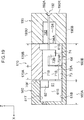
- the connector 110 of the other exemplary embodiment differs from that of the exemplary embodiment described above in that one end side (a connector rear side) of each terminal 120 is connected to an FPC 180 (flat wiring member) as a flexible wiring member instead of to the electric cable 80. Due to this difference, the base end portion 30 and the like of the terminal 120 differ from those of the connector 10 according to the exemplary embodiment described above. Moreover, in the other exemplary embodiment, unlike the exemplary embodiment described above, the FPC 180 serving as a flexible wiring member and a flat wiring member can be inserted and removed freely with respect to the connector 110 in an assembled state of the connector 110 (see Fig. 15 and Fig. 16 ).
- the connector 110 includes plural (six) of the terminals 120, a housing 160, a retainer 170, and a cover 190.
- the terminals 120 are accommodated in the housing 160 (see Fig. 13 ), after which the retainer 170 is fitted into the housing 160 in which the terminals 120 are accommodated (see Fig. 14 ), and the cover 190 is assembled, thereby assembling the connector 110 (see Fig. 15 ).
- the six terminals 120 have the same configuration as each other. One of the six terminals 120 is illustrated in Fig. 20 and Fig. 21 . Explanation follows regarding the terminal 120.
- the terminals 120 are, for example, formed by punching and then bending a sheet material.
- the material employed for the terminals 120 is a material with electrically conductive properties, such as a copper alloy.
- Each of the terminals 120 includes a base end portion 30 configuring one end side of the terminal 20, a leading end portion 50 configuring the other end side of the terminal 20, and a spring portion 40 positioned between the leading end portion 50 and the base end portion 30.
- the base end portion 30 extends from a rear end 20B of the terminal 120 toward the front.
- the base end portion 30 includes an FPC connection portion 131 and a base end side restricted portion 32 in this sequence on progression from the one end side to the other end side.
- the FPC connection portion 131 is a portion configured to connect to the FPC 180 that serves as a flexible wiring member, and corresponds to a flexible wiring member connection portion of the present invention.
- the FPC connection portion 131 includes contact portions 131A configured to contact the FPC 180 (see Fig. 18 ), and a displacement portion 131B configured such that a contact position with the FPC 180 is displaced toward a connector up-down direction intermediate side of the base end side restricted portion 32.
- the plate thickness direction of the FPC connection portion 131 is oriented in the connector width direction.
- the other end side (leading end side) of the FPC connection portion 131 is connected to a right side plate portion 34 of a base end side restricted portion 32 (to one of a pair of side plate portions 34), described later.
- the FPC connection portion 131 and the right side plate portion 34 are positioned in the same plane as each other.
- the contact portions 131A are formed in a pair, and contact the FPC 180 by nipping the FPC 180 from two faces.
- the base end side restricted portion 32 is a portion configured to abut the housing 160 and the retainer 170 in order to limit a movement range of the base end portion 30.
- the base end side restricted portion 32 is configured with an upward-opening U-shaped cross-section profile as sectioned orthogonally to the terminal front-rear direction.
- the base end side restricted portion 32 includes a bottom plate portion 33 extending in the width direction, the right side plate portion 34 extending upward from a right side end portion of the bottom plate portion 33, and a left side plate portion 34 extending upward from a left side end portion to bottom plate portion 33.
- the left side plate portion 34 and the right side plate portion 34 of the base end side restricted portion 32 are also collectively referred to as the pair of side plate portions 34 of the base end side restricted portion 32.
- Each of the side plate portions 34 includes a front-facing front face 34F, an upward-facing upper face 34U, and a rear-facing rear face 34R. Tapered faces 35 facing in an oblique direction running upward and toward the front are formed between the front faces 34F and the upper faces 34U.
- Each of the side plate portions 34 further includes an upward-facing second upper face 34U2.
- Each of the second upper faces 34U2 is formed so as to connect to a lower end of the rear face 34R, and is positioned lower than and to the rear of the upper face 34U.
- the bottom plate portion 33 of the base end side restricted portion 32 is formed with a lance 36.
- the lance 36 is formed by bending a width direction central portion of the bottom plate portion 33 downward (toward a plate thickness direction outer face side).
- the spring portion 40 includes a first linear portion 41, an inclined portion 42, a first bent portion 43, a second linear portion 44, and a second bent portion 45 in this sequence on progression from one end side toward the other end side.
- the structure of the spring portion 40 is the same as that of the spring portion 40 of the terminal 20 of the exemplary embodiment described above, and so explanation thereof is omitted.
- the leading end portion 50 includes a leading end side restricted portion 51 and a contact portion 52.
- the leading end side restricted portion 51 is a portion configured to abut the housing 160 and the retainer 170 in order to limit a movement range of the leading end portion 50.
- the structure of the leading end portion 50 is the same as that of the spring portion 50 of the terminal 20 of the exemplary embodiment described above, and so explanation thereof is omitted.
- the housing 160 is formed in a substantially rectangular block shape from an insulating body configured by a synthetic resin or the like.
- the housing 160 includes accommodation portions 161 configured to accommodate the terminals 120. Plural of the accommodation portions 161 are formed (six in the present exemplary embodiment, so as to correspond to the number of the terminals 120). The six accommodation portions 161 are configured similarly to each other, and are formed at uniform spacings in the housing width direction.
- the terminals 120 can be accommodated in the corresponding accommodation portions 161 by pushing the terminals 120 toward the front from the rear of the housing 160.
- a rear portion 160B of the housing 160 (housing rear portion 160B, see Fig. 19 ) is formed with a substantially rectangular shaped retainer-fitting opening 160BH that opens upward from the housing.
- the retainer-fitting opening 160BH is joined to the six accommodation portions 61. Atop face 61T (see Fig. 19 ) of the accommodation portions 161 is therefore not present at the housing rear portion 160B.
- left and right pairs of side wall faces 61S are formed lower than left and right side walls 60S of the housing 160.
- the side wall faces 61S of the housing rear portion 160B are interrupted at a front-rear direction intermediate position of the housing rear portion 160B. Namely, if the housing rear portion 160B is further divided into a front side and a rear side, the side wall faces 61S are formed at the rear side of the housing rear portion 160B, but the side wall faces 61S are not formed at the front side of the housing rear portion 160B.
- the base end side restricted portion 32 of the terminal 120 is disposed between the left and right pair of side wall faces 61S of the housing rear portion 160B (in the accommodation portions 161 of the housing rear portion 160B).
- the displacement portion 131B of the FPC connection portion 131 of each terminal 120 is disposed in the corresponding accommodation portion 61 in the housing rear portion 160B.
- the plural housing portions 161 are separated from each other in a front portion 160A (housing front portion 160A) of the housing 160. Namely, as illustrated in Fig. 19 , in the housing front portion 160A a left and right pair of the side wall faces 61S are formed spanning from the bottom face 61B to the top face 61T for each of the accommodation portions 161.
- part of the spring portion 40 (for example the first bent portion 43) and the leading end portion 50 of the corresponding terminal 120 are disposed between the left and right pair of side wall faces 61S in the housing front portion 160A (in the accommodation portion 61 in the housing front portion 60A).
- the spacing between each left and right pair of the side wall faces 61S is formed smaller than a width dimension of the leading end side restricted portion 51.
- recesses 62 are formed to increase the spacing between each left and right pair of the side wall faces 61S.
- a left and right pair of the recesses 62 is formed to each of the accommodation portions 61 such that the recesses 62 are formed to both of the left and right pair of side wall faces 61S.
- each left and right pair of the recesses 62 is formed so as to be the same as or larger than the width dimension of the leading end side restricted portion 51 of the terminal 120.
- An up-down dimension of each of the recesses 62 is formed so as to be the same as or larger than an up-down dimension of the leading end side restricted portion 51.
- a front-rear dimension of each of the recesses 62 is formed so as to be the same as or larger than a front-rear dimension of the leading end side restricted portion 51. Accordingly, in a state in which the leading end side restricted portion 51 has been pushed toward the front into the recesses 62, the leading end side restricted portion 51 does not project out into the housing intermediate portion 60B (the portion formed with the retainer-fitting opening 60BH).
- an upper portion of the accommodation portion 161 in the housing front portion 160A configures a leading end placement portion (an upper portion of the accommodation portion 161 in the housing front portion 160A) in which the leading end portion 50 of the terminal 120 is disposed, and a lower portion of the accommodation portion 61 in the housing front portion 60A configures a spring placement portion (a lower portion of the accommodation portion 161 in the housing front portion 160A) in which part of the spring portion 40 is disposed.
- the second bent portion 45 of the spring portion 40 is disposed in the accommodation portion 161 of the housing rear portion 160B.
- a terminal plug-in opening 61F is formed at the front side of the leading end placement portion (the upper portion of the accommodation portion 161 in the housing front portion 160A).
- the terminal plug-in opening 61F penetrates in the front-rear direction through a front wall of the housing 160 that partitions an external space in front of the housing 160 from the accommodation portion 161, and the terminal plug-in opening 61F has a rectangular cross-section profile as sectioned orthogonally to the housing front-rear direction.
- a side of the terminal plug-in opening 61F corresponding to a front face 60F of the housing 160 is formed with a tapered portion 61FA that gradually widens in the up-down and left-right directions on progression toward the front side of the housing.
- the leading end side restricted portion 51 of the terminal 120 In a state in which the leading end side restricted portion 51 of the terminal 120 has been disposed in the corresponding recesses 62, if the leading end portion 50 of the terminal 120 attempts to move in the connector forward direction, the right plate portion 51R of the leading end side restricted portion 51 abuts the corresponding recess 62 in the housing 160, and the left plate portion 51L of the leading end side restricted portion 51 abuts the corresponding recess 62 in the housing 160.
- the recesses 62 in the housing 160 (a leading end-forward restriction portion) thus limit a movement range of the leading end portion 50 toward the connector front.
- a movement range of the leading end portion 50 in the rearward direction is not limited by the housing 160.
- the base end side restricted portion 32 is disposed in the vicinity of a front end of the housing rear portion 160B between the left and right pair of side wall faces 61S. Note that the projections 63 (see Fig. 6 ) serving as abutting portions are not formed to the left and right pair of the side wall faces 61S of the housing rear portion 160B.
- the movement range of the base end portion 30 in the connector upward direction is not limited.
- a lance anchor hole 64 is formed in the bottom face 61B of each of the accommodation portions 161 at a position where the base end side restricted portion 32 is disposed.
- Each lance anchor hole 64 is formed penetrating the bottom face 61B, and is configured to anchor the lance 36 of the base end portion 30 of the corresponding terminal 120.
- the retainer 170 After the terminal 120 has been pushed into and accommodated in the corresponding accommodation portion 161 of the housing 160, the retainer 170 is fitted into the retainer-fitting opening 160BH in the housing 160. When this is performed, anchor portions 70SA formed to left and right side faces 70S of the retainer 170 are anchored by anchoring portions 60SA of the housing 160 (see Fig. 13 and Fig. 14 ).
- plural (six in the present exemplary embodiment, so as to correspond to the number of the terminals 120) spring placement grooves 171 with a depth direction oriented in the retainer upward direction are formed in the retainer 170.
- Each of the spring placement grooves 171 extends along the retainer front-rear direction, and the spring placement grooves 171 are arranged at uniform spacings in the retainer width direction.
- a pair of side wall faces 71S of each of the spring placement grooves 171 serves a similar function to the pair of side wall faces 61S of each of the accommodation portions 161 (see Fig. 19 ).
- the second bent portion 45 and the like of each terminal 120 are disposed between the pair of side wall faces 71S of the corresponding spring placement groove 171.
- a width dimension of each of the spring placement grooves 171 is formed so as to be larger than the width dimension of the spring portion 40 of the corresponding terminal 120, and so as to be smaller than a width dimension of the leading end side restricted portion 51 and a width dimension of the base end side restricted portion 32.
- a bottom face 71B of each of the spring placement grooves 171 serves a similar function to the top face 61T of the accommodation portion 161 (see Fig. 19 ).
- the bottom faces 71B of the respective spring placement grooves 171 are disposed at a position lower than the top face 61T of the housing front portion 60A.
- a state is adopted in which a front face 70F of the retainer 170 is disposed to the rear of the right plate portion 51R, the left plate portion 51L, and the upper plate portion 51T of the corresponding leading end side restricted portion 51.
- the right plate portion 51R, the left plate portion 51L, and the upper plate portion 51T of the leading end side restricted portion 51 abut the front face 70F of the retainer 170.
- the front face 70F of the retainer 170 (a leading end-rearward restriction portion) limits a movement range of the leading end portion 50 toward the connector rear.
- the housing 160 and the retainer 170 work in combination to prevent detachment of the leading end portion 50.
- the retainer 170 may also be said to include seven downward projections 172 separated by the six spring placement grooves 171.
- a front portion 170A (retainer front portion 170A) of the retainer 170 is disposed at a location where the side wall faces 61S are not formed to the housing rear portion 160B. Accordingly, downward projections 72A of the retainer front portion 170A are formed to project further downward. In the fitted state of the retainer 170, lower ends of the downward projections 72 are in a state either contacting or close to the bottom face 61B of the accommodation portion 161 at the retainer front portion 170A. Tapered portions 73 with gradually decreasing width dimensions and up-down dimensions are formed in the vicinity of the lower ends of the downward projections 72A of the front portion 170A.
- rear faces 72AR of the downward projections 72A of the retainer front portion 170A are disposed in front of the pair of side plate portions 34 of the base end side restricted portion 32 of the corresponding terminal 120.
- the front faces 34F of the left and right pair of side plate portions 34 of the base end side restricted portion 32 abut the rear faces 72AR of the downward projections 72A of the corresponding retainer front portion 70A.
- the rear faces 72AR (base end-forward restriction portions) of the downward projections 72A of the retainer front portion 170A limit a movement range of the base end portion 30 in the connector forward direction.
- a retainer rear portion 170B is disposed at a location of the housing rear portion 160B where the side wall faces 61S are formed. Downward projections 72B of the retainer rear portion 170B are therefore formed so as to project downward by a smaller amount than those at the retainer front portion 170A.
- base end-rearward restriction portions 74 are provided projecting further downward from a rear portion of each of the downward projections 72B of the retainer rear portion 170B.
- the base end-rearward restriction portions 74 are disposed at the rear of the pair of side plate portions 34 of the base end side restricted portion 32 of the terminal 120.
- the base end-rearward restriction portion 74 of the retainer 170 limit a movement range of the base end portion 30 in the connector rearward direction.
- the base end-rearward restriction portions 74 are disposed above the second upper faces 34U2 of the pair of side plate portions 34 of the base end side restricted portion 32 of the terminal 120.
- the base end-rearward restriction portion 74 of the retainer 170 limits the movement range of the base end portion 30 in the connector upward direction.
- the base end-rearward restriction portion 74 of the retainer 170 functions as an abutting portion that restricts the movement range of the base end portion 30 in the fitting-opposite direction of the retainer 170.
- the abutting portion is provided to the retainer 170 instead of the housing 160.
- the housing 160 may be formed with projections 63 (see Fig. 3 , etc.) as abutting portions in the present exemplary embodiment.
- the base end portion 30 is capable of moving with respect to the housing 160 and the retainer 170 in a predetermined movement range in the connector front-rear direction.
- the cover 190 is attached to the housing 160 from the rear side.
- anchor portions 190SA formed to left and right side walls 190S of the cover 190 are anchored by protrusion shaped anchoring portions 60SB formed to the left and right side walls 60S of the housing 160.
- an upper face 190U, a lower face 190B, the left and right side faces 190S, and a rear face 190R of the cover 190 configure outer surfaces of a rear portion of the connector 110.
- the upper face 190U and the lower face 190B of the cover 190 adopt states lying in substantially the same planes as upper faces and lower faces of the housing 160 and the retainer 170.
- the left and right side faces 190S of the cover 190 adopt states in which steps are formed between the left and right side faces 190S and the left and right side walls 60S of the housing 160.
- the cover 190 includes a flat wiring member insertion hole 192 for insertion of the FPC 180.
- An entry side of the flat wiring member insertion hole 192 is formed with a taper 192A to guide the FPC 180 in the up-down and left-right directions.
- the cover 190 includes a terminal accommodation portion 193 to accommodate the FPC connection portions 131 of the plural terminals 120.
- the terminal accommodation portion 193 is open toward the front.
- the cover 190 includes plural (five) partitioning walls 194 to partition the FPC connection portion 131 of the plural (six) terminals 120 from each other.
- Each of the partitioning walls 194 is formed with a flat wiring member placement groove 194A in which the FPC 180 is disposed.
- the connector 110 of the present exemplary embodiment includes the terminals 120, the housing 160, and the retainer 170.
- the retainer 170 is fitted to the housing 160 in which the terminals 120 are accommodated.
- Each of the terminals 120 includes the base end portion 30 provided with the FPC connection portion 131 that connects to the FPC 180, and the leading end portion 50 provided with the contact portion 52 that contacts the connection target 90. As illustrated in Fig. 18 , the housing 160 and the retainer 170 work in combination to prevent detachment of the leading end portion 50.
- the base end portion 30 is capable of moving with respect to the housing 160 and the retainer 170 in the connector front-rear direction that corresponds to an insertion/removal direction of the connection target 90.
- Each of the terminals 120 also includes the spring portion 40 positioned between the base end portion 30 and the leading end portion 50.
- the base end portion 30 provided with the FCP connection portion 131 moves in the connector front-rear direction with respect to the housing 160 and the retainer 170, enabling the effect of the flexing on the housing 160 and the retainer 170 to be reduced.
- the flexing can be suppressed from affecting the leading end portion 50 through the housing 160 and the retainer 170.
- the spring portion 40 positioned between the leading end portion 50 and the base end portion 30 deforms in response to this flexing, thereby enabling the effect of the flexing on the leading end portion 50 provided with the contact portion 52 to be reduced.
Landscapes
- Connector Housings Or Holding Contact Members (AREA)
Applications Claiming Priority (2)
| Application Number | Priority Date | Filing Date | Title |
|---|---|---|---|
| JP2017092783 | 2017-05-09 | ||
| PCT/JP2018/017104 WO2018207651A1 (fr) | 2017-05-09 | 2018-04-26 | Connecteur |
Publications (2)
| Publication Number | Publication Date |
|---|---|
| EP3624276A1 true EP3624276A1 (fr) | 2020-03-18 |
| EP3624276A4 EP3624276A4 (fr) | 2021-01-13 |
Family
ID=64105291
Family Applications (1)
| Application Number | Title | Priority Date | Filing Date |
|---|---|---|---|
| EP18799119.5A Withdrawn EP3624276A4 (fr) | 2017-05-09 | 2018-04-26 | Connecteur |
Country Status (5)
| Country | Link |
|---|---|
| US (1) | US20200083632A1 (fr) |
| EP (1) | EP3624276A4 (fr) |
| JP (1) | JPWO2018207651A1 (fr) |
| CN (1) | CN110651400A (fr) |
| WO (1) | WO2018207651A1 (fr) |
Families Citing this family (2)
| Publication number | Priority date | Publication date | Assignee | Title |
|---|---|---|---|---|
| CN116325375B (zh) | 2020-08-21 | 2026-04-21 | 日本端子株式会社 | 连接器 |
| JP7408611B2 (ja) * | 2021-10-20 | 2024-01-05 | 矢崎総業株式会社 | コネクタ |
Family Cites Families (15)
| Publication number | Priority date | Publication date | Assignee | Title |
|---|---|---|---|---|
| JP2527144Y2 (ja) * | 1992-11-19 | 1997-02-26 | モレックス インコーポレーテッド | プリント回路基板接続用電気コネクタ |
| JPH09106854A (ja) * | 1995-10-13 | 1997-04-22 | Yazaki Corp | 防水コネクタ用雌端子及び樹脂充填防水コネクタ |
| JP2001015213A (ja) * | 1999-06-28 | 2001-01-19 | Yazaki Corp | 半嵌合検知コネクタ |
| JP3544155B2 (ja) * | 1999-10-22 | 2004-07-21 | 住友電装株式会社 | 端子金具 |
| US7241190B2 (en) * | 2001-11-20 | 2007-07-10 | Fci Americas Technology, Inc. | Female electrical terminal and electrical connector comprising the same |
| US7112105B2 (en) * | 2003-07-22 | 2006-09-26 | Hon Hai Precision Ind. Co., Ltd. | Cable assembly having power contacts |
| JP2006073271A (ja) * | 2004-08-31 | 2006-03-16 | Tyco Electronics Amp Kk | 電気コネクタ |
| JP2010049844A (ja) * | 2008-08-19 | 2010-03-04 | Sumitomo Wiring Syst Ltd | コネクタ及び端子金具 |
| JP2010067432A (ja) * | 2008-09-10 | 2010-03-25 | Sumitomo Wiring Syst Ltd | コネクタ |
| CN102088136A (zh) * | 2009-12-03 | 2011-06-08 | 泰科电子(上海)有限公司 | 电连接端子 |
| JP2014186934A (ja) | 2013-03-25 | 2014-10-02 | Sumitomo Wiring Syst Ltd | ジョイントコネクタ |
| JP5747102B1 (ja) * | 2014-04-18 | 2015-07-08 | 日本航空電子工業株式会社 | 雌型コンタクト及び電源用コネクタ |
| JP5907300B1 (ja) * | 2015-04-30 | 2016-04-26 | 第一精工株式会社 | 導電端子 |
| JP6505582B2 (ja) | 2015-11-12 | 2019-04-24 | 株式会社フジクラ | 共振器アンテナ装置 |
| JP6123004B1 (ja) * | 2016-06-10 | 2017-04-26 | イリソ電子工業株式会社 | コネクタ |
-
2018
- 2018-04-26 WO PCT/JP2018/017104 patent/WO2018207651A1/fr not_active Ceased
- 2018-04-26 CN CN201880030002.1A patent/CN110651400A/zh active Pending
- 2018-04-26 US US16/611,164 patent/US20200083632A1/en not_active Abandoned
- 2018-04-26 JP JP2019517564A patent/JPWO2018207651A1/ja active Pending
- 2018-04-26 EP EP18799119.5A patent/EP3624276A4/fr not_active Withdrawn
Also Published As
| Publication number | Publication date |
|---|---|
| WO2018207651A1 (fr) | 2018-11-15 |
| JPWO2018207651A1 (ja) | 2020-03-12 |
| CN110651400A (zh) | 2020-01-03 |
| EP3624276A4 (fr) | 2021-01-13 |
| US20200083632A1 (en) | 2020-03-12 |
Similar Documents
| Publication | Publication Date | Title |
|---|---|---|
| EP3696921A1 (fr) | Connecteur | |
| US9017108B2 (en) | Electrical connector | |
| US7431617B2 (en) | Connector | |
| KR102806515B1 (ko) | 전기 커넥터 | |
| US10290966B2 (en) | Joint connector | |
| US10971851B2 (en) | Miniaturized connector with a terminal holding member | |
| KR101105537B1 (ko) | 분할형 커넥터 | |
| KR101594199B1 (ko) | 전기 커넥터 | |
| CN101779337B (zh) | 电连接器 | |
| JP2024177529A (ja) | コネクタ | |
| KR20100011831A (ko) | 프론트홀더가 구비된 커넥터 | |
| EP3624276A1 (fr) | Connecteur | |
| EP0982808A1 (fr) | Structure d'un connecteur électrique escamotable et procédé d'assemblage et de connexion d'une telle structure | |
| EP3633801A1 (fr) | Connecteur | |
| JP2025033719A (ja) | コネクタ及びコネクタ組立体 | |
| CN114628937B (zh) | 连接器 | |
| JP2016096152A (ja) | コネクタ | |
| CN119481779A (zh) | 电连接器 | |
| JP2012243562A (ja) | コネクタ端子及びこのコネクタ端子を含むカードエッジ型コネクタ | |
| US8070530B1 (en) | Modular jack | |
| JP2017228548A (ja) | コネクタ | |
| JP6937081B2 (ja) | コネクタ | |
| JP7725152B2 (ja) | コネクタ | |
| US20250323440A1 (en) | Electrical connector for flat conductor | |
| JP2002184511A (ja) | コネクタ |
Legal Events
| Date | Code | Title | Description |
|---|---|---|---|
| STAA | Information on the status of an ep patent application or granted ep patent |
Free format text: STATUS: THE INTERNATIONAL PUBLICATION HAS BEEN MADE |
|
| PUAI | Public reference made under article 153(3) epc to a published international application that has entered the european phase |
Free format text: ORIGINAL CODE: 0009012 |
|
| STAA | Information on the status of an ep patent application or granted ep patent |
Free format text: STATUS: REQUEST FOR EXAMINATION WAS MADE |
|
| 17P | Request for examination filed |
Effective date: 20191114 |
|
| AK | Designated contracting states |
Kind code of ref document: A1 Designated state(s): AL AT BE BG CH CY CZ DE DK EE ES FI FR GB GR HR HU IE IS IT LI LT LU LV MC MK MT NL NO PL PT RO RS SE SI SK SM TR |
|
| AX | Request for extension of the european patent |
Extension state: BA ME |
|
| DAV | Request for validation of the european patent (deleted) | ||
| DAX | Request for extension of the european patent (deleted) | ||
| A4 | Supplementary search report drawn up and despatched |
Effective date: 20201215 |
|
| RIC1 | Information provided on ipc code assigned before grant |
Ipc: H01R 11/05 20060101ALN20201209BHEP Ipc: H01R 4/18 20060101ALN20201209BHEP Ipc: H01R 13/11 20060101ALI20201209BHEP Ipc: H01R 13/533 20060101ALI20201209BHEP Ipc: H01R 13/24 20060101ALN20201209BHEP Ipc: H01R 13/42 20060101AFI20201209BHEP Ipc: H01R 13/436 20060101ALI20201209BHEP Ipc: H01R 13/432 20060101ALN20201209BHEP Ipc: H01R 12/77 20110101ALN20201209BHEP Ipc: H01R 13/631 20060101ALI20201209BHEP |
|
| STAA | Information on the status of an ep patent application or granted ep patent |
Free format text: STATUS: THE APPLICATION HAS BEEN WITHDRAWN |
|
| 18W | Application withdrawn |
Effective date: 20210118 |