WO2018207651A1 - Connecteur - Google Patents
Connecteur Download PDFInfo
- Publication number
- WO2018207651A1 WO2018207651A1 PCT/JP2018/017104 JP2018017104W WO2018207651A1 WO 2018207651 A1 WO2018207651 A1 WO 2018207651A1 JP 2018017104 W JP2018017104 W JP 2018017104W WO 2018207651 A1 WO2018207651 A1 WO 2018207651A1
- Authority
- WO
- WIPO (PCT)
- Prior art keywords
- housing
- retainer
- connector
- terminal
- base end
- Prior art date
- Legal status (The legal status is an assumption and is not a legal conclusion. Google has not performed a legal analysis and makes no representation as to the accuracy of the status listed.)
- Ceased
Links
Images







Classifications
-
- H—ELECTRICITY
- H01—ELECTRIC ELEMENTS
- H01R—ELECTRICALLY-CONDUCTIVE CONNECTIONS; STRUCTURAL ASSOCIATIONS OF A PLURALITY OF MUTUALLY-INSULATED ELECTRICAL CONNECTING ELEMENTS; COUPLING DEVICES; CURRENT COLLECTORS
- H01R13/00—Details of coupling devices of the kinds covered by groups H01R12/70 or H01R24/00 - H01R33/00
- H01R13/40—Securing contact members in or to a base or case; Insulating of contact members
- H01R13/42—Securing in a demountable manner
- H01R13/422—Securing in resilient one-piece base or case, e.g. by friction; One-piece base or case formed with resilient locking means
- H01R13/4223—Securing in resilient one-piece base or case, e.g. by friction; One-piece base or case formed with resilient locking means comprising integral flexible contact retaining fingers
-
- H—ELECTRICITY
- H01—ELECTRIC ELEMENTS
- H01R—ELECTRICALLY-CONDUCTIVE CONNECTIONS; STRUCTURAL ASSOCIATIONS OF A PLURALITY OF MUTUALLY-INSULATED ELECTRICAL CONNECTING ELEMENTS; COUPLING DEVICES; CURRENT COLLECTORS
- H01R13/00—Details of coupling devices of the kinds covered by groups H01R12/70 or H01R24/00 - H01R33/00
- H01R13/40—Securing contact members in or to a base or case; Insulating of contact members
- H01R13/42—Securing in a demountable manner
- H01R13/436—Securing a plurality of contact members by one locking piece or operation
- H01R13/4361—Insertion of locking piece perpendicular to direction of contact insertion
-
- H—ELECTRICITY
- H01—ELECTRIC ELEMENTS
- H01R—ELECTRICALLY-CONDUCTIVE CONNECTIONS; STRUCTURAL ASSOCIATIONS OF A PLURALITY OF MUTUALLY-INSULATED ELECTRICAL CONNECTING ELEMENTS; COUPLING DEVICES; CURRENT COLLECTORS
- H01R12/00—Structural associations of a plurality of mutually-insulated electrical connecting elements, specially adapted for printed circuits, e.g. printed circuit boards [PCB], flat or ribbon cables, or like generally planar structures, e.g. terminal strips, terminal blocks; Coupling devices specially adapted for printed circuits, flat or ribbon cables, or like generally planar structures; Terminals specially adapted for contact with, or insertion into, printed circuits, flat or ribbon cables, or like generally planar structures
- H01R12/70—Coupling devices
- H01R12/77—Coupling devices for flexible printed circuits, flat or ribbon cables or like structures
- H01R12/771—Details
- H01R12/774—Retainers
-
- H—ELECTRICITY
- H01—ELECTRIC ELEMENTS
- H01R—ELECTRICALLY-CONDUCTIVE CONNECTIONS; STRUCTURAL ASSOCIATIONS OF A PLURALITY OF MUTUALLY-INSULATED ELECTRICAL CONNECTING ELEMENTS; COUPLING DEVICES; CURRENT COLLECTORS
- H01R13/00—Details of coupling devices of the kinds covered by groups H01R12/70 or H01R24/00 - H01R33/00
- H01R13/02—Contact members
- H01R13/10—Sockets for co-operation with pins or blades
- H01R13/11—Resilient sockets
- H01R13/112—Resilient sockets forked sockets having two legs
-
- H—ELECTRICITY
- H01—ELECTRIC ELEMENTS
- H01R—ELECTRICALLY-CONDUCTIVE CONNECTIONS; STRUCTURAL ASSOCIATIONS OF A PLURALITY OF MUTUALLY-INSULATED ELECTRICAL CONNECTING ELEMENTS; COUPLING DEVICES; CURRENT COLLECTORS
- H01R13/00—Details of coupling devices of the kinds covered by groups H01R12/70 or H01R24/00 - H01R33/00
- H01R13/40—Securing contact members in or to a base or case; Insulating of contact members
- H01R13/42—Securing in a demountable manner
- H01R13/436—Securing a plurality of contact members by one locking piece or operation
- H01R13/4361—Insertion of locking piece perpendicular to direction of contact insertion
- H01R13/4362—Insertion of locking piece perpendicular to direction of contact insertion comprising a temporary and a final locking position
-
- H—ELECTRICITY
- H01—ELECTRIC ELEMENTS
- H01R—ELECTRICALLY-CONDUCTIVE CONNECTIONS; STRUCTURAL ASSOCIATIONS OF A PLURALITY OF MUTUALLY-INSULATED ELECTRICAL CONNECTING ELEMENTS; COUPLING DEVICES; CURRENT COLLECTORS
- H01R13/00—Details of coupling devices of the kinds covered by groups H01R12/70 or H01R24/00 - H01R33/00
- H01R13/46—Bases; Cases
- H01R13/533—Bases, cases made for use in extreme conditions, e.g. high temperature, radiation, vibration, corrosive environment, pressure
-
- H—ELECTRICITY
- H01—ELECTRIC ELEMENTS
- H01R—ELECTRICALLY-CONDUCTIVE CONNECTIONS; STRUCTURAL ASSOCIATIONS OF A PLURALITY OF MUTUALLY-INSULATED ELECTRICAL CONNECTING ELEMENTS; COUPLING DEVICES; CURRENT COLLECTORS
- H01R13/00—Details of coupling devices of the kinds covered by groups H01R12/70 or H01R24/00 - H01R33/00
- H01R13/62—Means for facilitating engagement or disengagement of coupling parts or for holding them in engagement
- H01R13/629—Additional means for facilitating engagement or disengagement of coupling parts, e.g. aligning or guiding means, levers, gas pressure electrical locking indicators, manufacturing tolerances
- H01R13/631—Additional means for facilitating engagement or disengagement of coupling parts, e.g. aligning or guiding means, levers, gas pressure electrical locking indicators, manufacturing tolerances for engagement only
- H01R13/6315—Additional means for facilitating engagement or disengagement of coupling parts, e.g. aligning or guiding means, levers, gas pressure electrical locking indicators, manufacturing tolerances for engagement only allowing relative movement between coupling parts, e.g. floating connection
-
- H—ELECTRICITY
- H01—ELECTRIC ELEMENTS
- H01R—ELECTRICALLY-CONDUCTIVE CONNECTIONS; STRUCTURAL ASSOCIATIONS OF A PLURALITY OF MUTUALLY-INSULATED ELECTRICAL CONNECTING ELEMENTS; COUPLING DEVICES; CURRENT COLLECTORS
- H01R11/00—Individual connecting elements providing two or more spaced connecting locations for conductive members which are, or may be, thereby interconnected, e.g. end pieces for wires or cables supported by the wire or cable and having means for facilitating electrical connection to some other wire, terminal, or conductive member, blocks of binding posts
- H01R11/03—Individual connecting elements providing two or more spaced connecting locations for conductive members which are, or may be, thereby interconnected, e.g. end pieces for wires or cables supported by the wire or cable and having means for facilitating electrical connection to some other wire, terminal, or conductive member, blocks of binding posts characterised by the relationship between the connecting locations
- H01R11/05—Individual connecting elements providing two or more spaced connecting locations for conductive members which are, or may be, thereby interconnected, e.g. end pieces for wires or cables supported by the wire or cable and having means for facilitating electrical connection to some other wire, terminal, or conductive member, blocks of binding posts characterised by the relationship between the connecting locations the connecting locations having different types of direct connections
-
- H—ELECTRICITY
- H01—ELECTRIC ELEMENTS
- H01R—ELECTRICALLY-CONDUCTIVE CONNECTIONS; STRUCTURAL ASSOCIATIONS OF A PLURALITY OF MUTUALLY-INSULATED ELECTRICAL CONNECTING ELEMENTS; COUPLING DEVICES; CURRENT COLLECTORS
- H01R12/00—Structural associations of a plurality of mutually-insulated electrical connecting elements, specially adapted for printed circuits, e.g. printed circuit boards [PCB], flat or ribbon cables, or like generally planar structures, e.g. terminal strips, terminal blocks; Coupling devices specially adapted for printed circuits, flat or ribbon cables, or like generally planar structures; Terminals specially adapted for contact with, or insertion into, printed circuits, flat or ribbon cables, or like generally planar structures
- H01R12/70—Coupling devices
- H01R12/77—Coupling devices for flexible printed circuits, flat or ribbon cables or like structures
- H01R12/778—Coupling parts carrying sockets, clips or analogous counter-contacts
-
- H—ELECTRICITY
- H01—ELECTRIC ELEMENTS
- H01R—ELECTRICALLY-CONDUCTIVE CONNECTIONS; STRUCTURAL ASSOCIATIONS OF A PLURALITY OF MUTUALLY-INSULATED ELECTRICAL CONNECTING ELEMENTS; COUPLING DEVICES; CURRENT COLLECTORS
- H01R13/00—Details of coupling devices of the kinds covered by groups H01R12/70 or H01R24/00 - H01R33/00
- H01R13/02—Contact members
- H01R13/22—Contacts for co-operating by abutting
- H01R13/24—Contacts for co-operating by abutting resilient; resiliently-mounted
- H01R13/2407—Contacts for co-operating by abutting resilient; resiliently-mounted characterized by the resilient means
- H01R13/2428—Contacts for co-operating by abutting resilient; resiliently-mounted characterized by the resilient means using meander springs
-
- H—ELECTRICITY
- H01—ELECTRIC ELEMENTS
- H01R—ELECTRICALLY-CONDUCTIVE CONNECTIONS; STRUCTURAL ASSOCIATIONS OF A PLURALITY OF MUTUALLY-INSULATED ELECTRICAL CONNECTING ELEMENTS; COUPLING DEVICES; CURRENT COLLECTORS
- H01R13/00—Details of coupling devices of the kinds covered by groups H01R12/70 or H01R24/00 - H01R33/00
- H01R13/40—Securing contact members in or to a base or case; Insulating of contact members
- H01R13/42—Securing in a demountable manner
- H01R13/428—Securing in a demountable manner by resilient locking means on the contact members; by locking means on resilient contact members
- H01R13/432—Securing in a demountable manner by resilient locking means on the contact members; by locking means on resilient contact members by stamped-out resilient tongue snapping behind shoulder in base or case
-
- H—ELECTRICITY
- H01—ELECTRIC ELEMENTS
- H01R—ELECTRICALLY-CONDUCTIVE CONNECTIONS; STRUCTURAL ASSOCIATIONS OF A PLURALITY OF MUTUALLY-INSULATED ELECTRICAL CONNECTING ELEMENTS; COUPLING DEVICES; CURRENT COLLECTORS
- H01R2201/00—Connectors or connections adapted for particular applications
- H01R2201/26—Connectors or connections adapted for particular applications for vehicles
-
- H—ELECTRICITY
- H01—ELECTRIC ELEMENTS
- H01R—ELECTRICALLY-CONDUCTIVE CONNECTIONS; STRUCTURAL ASSOCIATIONS OF A PLURALITY OF MUTUALLY-INSULATED ELECTRICAL CONNECTING ELEMENTS; COUPLING DEVICES; CURRENT COLLECTORS
- H01R4/00—Electrically-conductive connections between two or more conductive members in direct contact, i.e. touching one another; Means for effecting or maintaining such contact; Electrically-conductive connections having two or more spaced connecting locations for conductors and using contact members penetrating insulation
- H01R4/10—Electrically-conductive connections between two or more conductive members in direct contact, i.e. touching one another; Means for effecting or maintaining such contact; Electrically-conductive connections having two or more spaced connecting locations for conductors and using contact members penetrating insulation effected solely by twisting, wrapping, bending, crimping, or other permanent deformation
- H01R4/18—Electrically-conductive connections between two or more conductive members in direct contact, i.e. touching one another; Means for effecting or maintaining such contact; Electrically-conductive connections having two or more spaced connecting locations for conductors and using contact members penetrating insulation effected solely by twisting, wrapping, bending, crimping, or other permanent deformation by crimping
- H01R4/183—Electrically-conductive connections between two or more conductive members in direct contact, i.e. touching one another; Means for effecting or maintaining such contact; Electrically-conductive connections having two or more spaced connecting locations for conductors and using contact members penetrating insulation effected solely by twisting, wrapping, bending, crimping, or other permanent deformation by crimping for cylindrical elongated bodies, e.g. cables having circular cross-section
- H01R4/184—Electrically-conductive connections between two or more conductive members in direct contact, i.e. touching one another; Means for effecting or maintaining such contact; Electrically-conductive connections having two or more spaced connecting locations for conductors and using contact members penetrating insulation effected solely by twisting, wrapping, bending, crimping, or other permanent deformation by crimping for cylindrical elongated bodies, e.g. cables having circular cross-section comprising a U-shaped wire-receiving portion
- H01R4/185—Electrically-conductive connections between two or more conductive members in direct contact, i.e. touching one another; Means for effecting or maintaining such contact; Electrically-conductive connections having two or more spaced connecting locations for conductors and using contact members penetrating insulation effected solely by twisting, wrapping, bending, crimping, or other permanent deformation by crimping for cylindrical elongated bodies, e.g. cables having circular cross-section comprising a U-shaped wire-receiving portion combined with a U-shaped insulation-receiving portion
Definitions
- the present invention relates to a connector.
- Patent Document 1 Conventionally, a connector as described in Patent Document 1 is used for connection of internal wiring of an automobile or the like.
- the connector described in Patent Literature 1 is housed in a housing, a crimp terminal that is accommodated in the housing, is connected to an object to be connected at one end (terminal portion), and is crimp-connected to an electric wire at the other end (barrel portion). And a retainer to be fitted. When the retainer is fitted into the housing, the crimp terminal connected to the electric wire is prevented from coming off in the housing. In such a connector, workability is good because the connector can be handled relatively freely by utilizing the flexibility of the electric wire during the connection work between the connector and the connection object.
- the crimp terminal accommodated in the housing may be pulled or pushed into the electric wire. Then, there exists a possibility that sliding may occur in the contact part with the connection target in one end (terminal part) in the crimp terminal.
- the target to be connected to the other end of the terminal is not an electric wire, but FPC (Flexible printed circuits, flexible printed circuit board, flexible printed wiring board) or FFC (Flexible ⁇ ⁇ ⁇ ⁇ ⁇ ⁇ Flat Cable, flexible flat cable) (That is, an FPC connector and an FFC connector may be considered). Since FPC and FFC have the same flexibility as electric wires, they may be bent, and in that case, the influence of the bending may be transmitted to the terminals as in the case of electric wires, and contact sliding may occur.
- FPC Flexible printed circuits, flexible printed circuit board, flexible printed wiring board
- FFC Flexible ⁇ ⁇ ⁇ ⁇ ⁇ ⁇ ⁇ Flat Cable, flexible flat cable
- the present invention has been made in view of the above problems, and its purpose is a contact when a flexible wiring material (electric wire, FPC, FFC, etc.) is bent by vibration or impact. It is an object of the present invention to provide a connector capable of suppressing the sliding.
- a connector is a connector comprising: a terminal that is conductively connected to a connection object to be inserted / extracted; a housing that houses the terminal; and a retainer that fits into the housing that houses the terminal.
- the terminal includes a base end portion having a flexible wiring material connecting portion connected to a flexible wiring material, a tip end portion having a contact portion in contact with the connection object, the base end portion, and the base end portion.
- a spring portion positioned between the distal end portion and the distal end portion is prevented from coming off by a combination of the housing and the retainer or by the housing, and the retainer is fitted into the housing.
- the base end portion is movable in the longitudinal direction of the connector, which is the insertion / extraction direction of the connection object, with respect to the housing within a predetermined movable range.
- the connector includes a terminal, a housing, and a retainer.
- a retainer is fitted into the housing that houses the terminal.
- the terminal has a distal end portion having a contact portion that comes into contact with the connection object, and the distal end portion is prevented from being detached by a combination of the above-described housing and retainer, or (for example, press-fitted into the housing). It is prevented from coming off by the housing.
- the base end portion is movable in the connector front-rear direction, which is the insertion / extraction direction of the connection object with respect to the housing.
- the terminal has a spring part located between a base end part and a front-end
- the proximal end portion having the movement in the connector front-rear direction with respect to the housing can suppress the housing from being affected by this bending. As a result, it is possible to suppress the influence of the deflection from reaching the tip portion through the housing.
- the movement of the base end portion in the longitudinal direction of the connector relative to the housing is limited to a predetermined movable range. For this reason, it is suppressed that a spring part deforms plastically.
- the connector according to a second aspect is the connector according to the first aspect, wherein the housing has a tip placement portion on which the tip portion can be placed, and the tip placement portion removes the connection object.
- a connector front-restricting portion that restricts a range of movement of the tip portion in the connector front direction, which is the direction of the connector, and the retainer is a connector rear direction in which the connection object is inserted in a state of being fitted to the housing And a rear end restricting portion for restricting the movement range of the front end portion.
- the housing has a tip placement portion on which the tip portion can be placed, and the tip placement portion has a tip front restricting portion that limits a movement range of the tip portion in the connector front direction.
- the retainer has a rear end restricting portion that restricts a range of movement of the front end portion in the rear direction of the connector in a state where the retainer is fitted to the housing. For this reason, when the terminal is accommodated in the housing, the terminal can be temporarily positioned with respect to the housing by pushing the terminal until the distal end portion of the terminal comes into contact with the front end restricting portion of the distal end arrangement portion. Then, by attaching the retainer to the housing thereafter, the tip of the terminal is prevented from coming off. Therefore, it can be assembled easily.
- the connector according to a third aspect is the connector according to the first or second aspect, wherein the housing includes a bottom portion that restricts movement of the base end portion in the fitting direction of the retainer, and a fitting direction of the retainer. And an abutting portion that regulates the movement range of the base end portion in the counter-fitting direction that is the opposite direction.
- the housing has a bottom portion that restricts movement of the proximal end portion of the retainer in the fitting direction, and a movement of the proximal end portion in the opposite fitting direction that is opposite to the fitting direction of the retainer.
- a contact portion for regulating the range For this reason, after the terminal is accommodated in the housing and in a state where the retainer is not fitted to the housing, the base end portion is prevented from moving greatly in the fitting direction or the counter-fitting direction. Therefore, the connector can be easily assembled.
- the connector according to a fourth aspect is the connector according to the third aspect, wherein the retainer of the base end portion is fitted and counterfitted between the base end portion, the bottom portion, and the contact portion. There is a movable gap that allows the connector to move in the vertical direction, and the base end portion is movable in a predetermined movement range in the connector vertical direction in a state where the retainer is fitted to the housing.
- the connector according to the fourth aspect there is a movable gap that allows the base end portion to move in the vertical direction of the connector between the base end portion, the bottom portion, and the contact portion, and the retainer is fitted to the housing.
- the base end portion is movable in a predetermined movement range in the vertical direction of the connector. For this reason, even if the flexible wiring material is bent so as to move the terminal in the vertical direction of the connector, it is possible to reduce the influence of the housing and the retainer due to this bending. As a result, it is possible to suppress the influence of this bending from reaching the tip portion via the housing and the retainer.
- the spring portion positioned between the distal end portion and the proximal end portion is not provided.
- tip part which has a contact part receives from this bending can be reduced. Furthermore, since the range in which the base end portion moves in the vertical direction of the connector is restricted within a predetermined range, the plastic deformation of the spring portion is suppressed.
- the connector according to a fifth aspect is the connector according to any one of the first to fourth aspects, wherein the base end portion is a direction perpendicular to both the insertion direction of the connection object and the fitting direction of the retainer.
- the housing In the connector width direction, the housing is accommodated in a state where there is a gap with respect to the housing, and in a state where the retainer is fitted to the housing, the base end portion is in the range of the gap in the connector width direction. It is possible to move.
- the base end portion is accommodated in a state where there is a gap with respect to the housing in the connector width direction which is a direction perpendicular to both the insertion direction of the connection object and the fitting direction of the retainer.
- the base end portion can move in the connector width direction within the gap. That is, in a state where the retainer is fitted to the housing, the retainer can move within a predetermined movement range in the left-right direction of the connector. For this reason, even if the flexible wiring material is bent so as to move the terminal in the left-right direction of the connector, it is possible to reduce the influence of the housing and the retainer from this bending.
- the connector according to a sixth aspect is the connector according to any one of the first to fifth aspects, wherein the insertion / extraction shaft of the contact portion is substantially parallel to the connection axis of the flexible wiring member connection portion, and The position of the retainer in the fitting direction is shifted.
- the insertion / extraction shaft of the contact portion is substantially parallel to the connection shaft of the flexible wiring member connection portion, and the position of the retainer in the fitting direction is displaced, so the front-rear direction of the connector.
- the connector according to a seventh aspect is the connector according to the sixth aspect, wherein the spring portion includes a folded portion that is folded back in the connector rear direction, which is the insertion direction of the connection object.
- the connector in addition to the insertion / extraction shaft and the connection shaft of the flexible wiring member connection portion being arranged with the position in the connector vertical direction being shifted, the connector extends from the proximal end portion to the distal end portion.
- the spring portion includes a folded portion that is folded back in the connector rear direction. For this reason, the ease of deformation of the spring portion can be further ensured, and the sliding at the contact can be more effectively suppressed.
- the present invention has an excellent effect that it is possible to suppress sliding at the contact when the electric wire is bent due to vibration or impact.
- FIG. 8 It is a sectional side view corresponding to FIG. 8 which shows the state by which the electric wire was pushed in the assembly state. It is sectional drawing (sectional drawing when cut
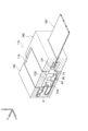
- FIG. 15 is a perspective view showing a connector in a state where a cover is attached from the state of FIG. 14, that is, an assembled state.
- FIG. 17 is a cross-sectional perspective view corresponding to the state illustrated in FIG. 16. It is sectional drawing which looked at FIG. 17 from the connector side. It is sectional drawing which abbreviate
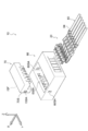
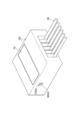
- the connector 10 of this embodiment includes a plurality (six) of terminals 20, a housing 60, and a retainer 70.
- the terminal 20 is accommodated in the housing 60, and then the retainer 70 is fitted into the housing 60 accommodating the terminal 20, whereby the connector 10 is assembled (see FIG. 2).
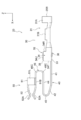
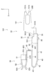
- the six terminals 20 have the same configuration. One of the six terminals 20 is shown in FIGS. Hereinafter, the terminal 20 will be described with reference to FIGS. 4 and 5.
- the arrow X shown in FIG. 4 and FIG. 5 is described as the terminal front direction, the arrow Y as one side in the terminal width direction (left direction), and the arrow Z as the terminal upward direction.
- front and rear, top and bottom, width (left and right) are used unless otherwise specified, front and rear in the front and rear direction of the terminal, vertical and vertical in the terminal vertical direction, and width (left and right) in the terminal width (left and right) direction are indicated.
- the front and rear, left and right, and up and down directions of the terminal 20 substantially coincide with the front and rear, left and right, and up and down directions of the connector 10.
- the terminal 20 is formed by, for example, bending after a plate material is punched.
- the material of the terminal 20 is a conductive material such as a copper alloy, for example.
- the terminal 20 has a proximal end portion 30 on one end side, a distal end portion 50 on the other end side, and a spring portion 40 positioned between the distal end portion 50 and the proximal end portion 30.
- the base end portion 30 has a U-shape or a C-shape in which both sides in the width direction are bent upward (in the thickness direction inner surface side) as a whole, and a cross-sectional shape perpendicular to the front-rear direction is opened upward. .
- the base end portion 30 extends forward from the rear end 20 ⁇ / b> B of the terminal 20.
- the base end part 30 has the electric wire connection part 31 and the base end side controlled part 32 in this order toward the other end side from the one end side.
- the electric wire connecting portion 31 is a portion connected to the electric wire 80 as the “flexible wiring material”, and corresponds to the “flexible wiring material connecting portion” of the present invention.
- the wire connection portion 31 includes a cover crimp portion 31A that is crimped to the sheath 84 of the electric wire 80 (see FIG. 1) and a core wire crimp portion 31B that is crimped to the core wire 82 (see FIG. 3) of the wire 80.
- the base end side restricted portion 32 is a portion for restricting the movement range of the base end portion 30 by contacting the housing 60 and the retainer 70.
- the proximal-side regulated portion 32 has a U shape in which a cross-sectional shape orthogonal to the terminal front-rear direction is opened upward. That is, the base-side regulated portion 32 includes a bottom plate portion 33 extending in the width direction, a right plate portion 34 extending upward from the right end portion of the bottom plate portion 33, and a left plate extending upward from the left end portion of the bottom plate portion 33. Part 34.
- the right side plate portion 34 and the left side plate portion 34 of the base end side restricted portion 32 may be collectively referred to as a pair of side plate portions 34 of the base end side restricted portion 32.
- the side plate part 34 has a front surface 34F facing forward, an upper surface 34U facing upward, and a rear surface 34R facing rearward. Further, a tapered surface 35 is formed between the front surface 34F and the upper surface 34U and faces forward and upward in an oblique direction.
- a lance 36 is formed on the bottom plate portion 33 of the base end side restricted portion 32.
- the lance 36 is formed by bending the center portion in the width direction of the bottom plate portion 33 downward (outer surface side in the plate thickness direction).
- the spring part 40 has the 1st linear part 41, the inclination part 42, the 1st curved part 43, the 2nd linear part 44, and the 2nd curved part 45 in this order toward the other end side from the one end side.
- the spring portion 40 has substantially the same width dimension from one end to the other end, and the width dimension is smaller than the width dimension of the proximal-side regulated portion 32, specifically, one third or less. It is said that.
- the first straight portion 41 extends forward from the central portion in the width direction of the bottom plate portion 33 in the base end side restricted portion 32.
- the first straight portion 41 has a plate thickness direction in the up-down direction, and extends linearly in the forward direction from one end to the other end.
- the extending direction of the first linear portion 41 is substantially parallel to the front-rear direction of the terminal.
- the other end side of the first linear portion 41 is connected to the inclined portion 42 through a bent portion that is slightly bent toward the inner surface side in the thickness direction.
- the inclined portion 42 has a plate thickness direction substantially in the vertical direction, and extends linearly in a direction slightly inclined upward (forward and diagonally forward) from one end to the other end with respect to the front direction. .
- the angle formed by the extending direction of the inclined portion 42 and the terminal front-rear direction is an angle of less than 45 degrees, and in the present embodiment, the angle is approximately 20 degrees.
- the other end side in the extending direction of the inclined portion 42 is connected to the first curved portion 43.
- the first curved portion 43 is bent toward the inner surface side in the thickness direction, and has a convexly curved shape.
- the first curved portion 43 changes the direction of extension from one end to the other end by approximately 160 degrees.
- the other end side in the extending direction of the first curved portion 43 is connected to the second linear portion 44.
- the second straight portion 44 has the plate thickness direction in the up-down direction, and extends linearly backward from one end to the other end.
- the extending direction of the second straight portion 44 is substantially parallel to the front-rear direction of the terminal.
- the other end side in the extending direction of the second linear portion 44 is connected to the second curved portion 45.
- the second curved portion 45 is bent toward the outer surface side in the thickness direction, and has a convex shape rearward. Specifically, the second curved portion 45 includes two bent portions 45C bent by approximately 90 degrees. The extending direction of the second curved portion 45 is changed by approximately 180 degrees from one end to the other end. The other end side in the extending direction of the second curved portion 45 is connected to the tip-side restricted portion 51 of the tip portion 50.
- the distal end portion 50 includes a distal end side restricted portion 51 and a contact portion 52.
- the tip side restricted portion 51 is a portion for limiting the movement range of the tip portion 50 by contacting the housing 60 and the retainer 70.
- the contact part 52 is a part that contacts the connection object 90.
- the front end side restricted portion 51 has a substantially rectangular cross-sectional shape in the front-rear direction.
- the tip side restricted portion 51 includes a lower plate portion 51B, a right plate portion 51R extending upward from the right end portion of the lower plate portion 51B, and an upper plate portion extending leftward from the upper end of the right plate portion 51R.
- 51T and the left board part 51L extended below from the left side edge part of the upper board part 51T.
- the spring part 40 is connected to the center part in the width direction at the rear end of the lower plate part 51B.
- the contact part 52 has a pair of contact piece parts 52A.
- Each of the pair of contact piece portions 52A extends forward from the center in the width direction at the front end of the upper plate portion 51T and the lower plate portion 51B of the tip side regulated portion 51 of the tip portion 50.
- the pair of contact piece portions 52 ⁇ / b> A are electrically connected to each other by contacting the connection object 90 in the vertical direction.
- the housing 60 is formed in a substantially rectangular parallelepiped shape by an insulator such as synthetic resin.
- the arrow X is the front direction of the housing
- the arrow Y is the one side in the housing width direction (left direction)
- the arrow Z is the upward direction of the housing.
- front and rear, top and bottom, width (left and right) are used, the front and rear in the front and rear direction of the housing, the top and bottom in the top and bottom direction of the housing, and the width (left and right) in the housing width (left and right) direction are used.
- the front / rear, left / right and up / down directions of the housing 60 coincide with the front / rear, left / right and up / down directions of the connector 10.
- the housing 60 has an accommodating portion 61 that accommodates the terminal 20.
- the accommodating portion 61 is a space formed in the housing 60 and extending in the front-rear direction, and is formed in plural (six in this embodiment corresponding to the number of terminals 20).
- the six accommodating portions 61 have the same configuration as each other, and are formed at equal intervals along the housing width direction.
- FIG. 6 is a cross-sectional view of the six storage portions 61 taken along a plane perpendicular to the lateral direction of the housing at the center in the width direction of the leftmost storage portion 61.
- the illustration of the terminal 20 corresponding to the leftmost accommodating part 61 is omitted, and the other accommodating part 61 shows a state where the terminal 20 is accommodated.
- a terminal push-in opening 61R is formed on the rear surface 60R of the housing 60, and the terminal push-in opening 61R is connected to the accommodating portion 61.
- the terminal 20 is accommodated in the accommodating portion 61 by pushing the terminal 20 into the accommodating portion 61 from the terminal insertion opening 61R. Specifically, as shown in FIG. 1, the terminal 20 is pushed forward from the terminal push-in opening 61 ⁇ / b> R on the rear surface 60 ⁇ / b> R of the housing 60 with the front / rear / left / right direction of the terminal 20 and the front / rear / left / right direction of the housing 60 aligned.
- the terminal 20 can be accommodated in the accommodating portion 61.
- a substantially rectangular retainer fitting opening 60 ⁇ / b> BH that opens upward in the housing is formed in the front-rear direction intermediate portion 60 ⁇ / b> B (housing intermediate portion 60 ⁇ / b> B) of the housing 60.
- the retainer fitting opening 60 ⁇ / b> BH is connected to the six accommodating portions 61. Therefore, the ceiling surface 61T of the accommodating part 61 does not exist in the housing middle part 60B.
- the plurality of accommodating portions 61 are separated from each other. That is, in the housing rear portion 60C, a pair of left and right side wall surfaces 61S is formed from the bottom surface 61B to the ceiling surface 61T for each housing portion 61. As illustrated in FIG. 3, the electric wire connection portion 31 and the electric wire 80 of the base end portion 30 of the terminal 20 are disposed between the pair of left and right side wall surfaces 61 ⁇ / b> S in the housing rear portion 60 ⁇ / b> C.
- the pair of left and right side wall surfaces 61S are formed lower than the side wall surface 61S of the housing rear portion 60C.
- the height of the side wall surface 61S of the housing middle portion 60B is lower than the ceiling surface 61T of the housing rear portion 60C.
- the side wall surface 61S of the housing intermediate portion 60B is interrupted at the intermediate position in the front-rear direction of the housing intermediate portion 60B. That is, when the housing intermediate portion 60B is further divided into the front side and the rear side, the side wall surface 61S is formed on the rear side of the housing intermediate portion 60B, but the side wall surface 61S is formed on the front side of the housing intermediate portion 60B.
- the base-side regulated portion 32 of the terminal 20 is disposed between the pair of left and right side wall surfaces 61S of the housing intermediate portion 60B (the accommodating portion 61 in the housing intermediate portion 60B).
- the plurality of accommodating parts 61 are separated from each other. That is, in the housing front portion 60A, a pair of left and right side wall surfaces 61S is formed from the bottom surface 61B to the ceiling surface 61T for each accommodating portion 61.
- the height of the ceiling surface 61T of the housing rear portion 60C and the ceiling surface 61T of the housing front portion 60A are the same. As shown in FIG.
- a tip 50 is arranged.
- the distance between the pair of left and right side wall surfaces 61S (the width dimension of the accommodating portion 61) is larger than the width dimension of the distal-side regulated portion 51 and the proximal-side regulated portion 32 of the terminal 20. Largely formed.
- the distal-side restricted portion 51 and the proximal-side restricted portion 32 can pass in the front-rear direction between the pair of left and right side wall surfaces 61S of the housing rear portion 60C. ing.
- the base-side regulated portion 32 can be disposed between the pair of left and right side wall surfaces 61S of the housing intermediate portion 60B in a state where the terminal 20 is accommodated in the accommodating portion 61.
- the distance between the pair of left and right side wall surfaces 61 ⁇ / b> S is formed to be smaller than the width dimension of the front end side restricted portion 51.
- a recess 62 that enlarges the distance between the pair of left and right side wall surfaces 61S is formed in a portion adjacent to the housing middle portion 60B in the housing front portion 60A and in the vicinity of the ceiling surface 61T.
- the recesses 62 are formed on both the pair of left and right side wall surfaces 61 ⁇ / b> S, and a pair of left and right sides are formed for each storage portion 61.
- the distance between the pair of left and right recesses 62 is formed to be equal to or larger than the width dimension of the tip side restricted portion 51 of the terminal 20. Further, the vertical dimension of the recess 62 is formed to be the same as or larger than the vertical dimension of the front end side restricted portion 51.
- the front-rear dimension of the recess 62 is formed to be the same as or larger than the front-rear dimension of the front end side restricted part 51. For this reason, in a state where the front end side restricted portion 51 is pushed forward into the concave portion 62, the front end side restricted portion 51 does not protrude into the housing intermediate portion 60B (the portion where the retainer fitting port 60BH is formed). It has become.
- the upper portion of the accommodating portion 61 in the housing front portion 60 ⁇ / b> A is the tip arrangement portion (the front housing portion) where the tip portion 50 of the terminal 20 is arranged.
- the upper portion of the accommodating portion 61 in the portion 60A) and the lower portion become a spring arrangement portion (a lower portion of the accommodating portion 61 in the housing front portion 60A) where a part of the spring portion 40 is arranged.
- the second curved portion 45 of the spring portion 40 is disposed in the accommodating portion 61 in the housing intermediate portion 60B.
- a terminal insertion port 61F is formed on the front side of the tip arrangement portion (the upper portion of the housing portion 61 in the housing front portion 60A).
- the terminal insertion port 61F passes through the front wall of the housing 60 that separates the outer space in front of the housing 60 and the accommodating portion 61 in the front-rear direction, and the cross-sectional shape orthogonal to the front-rear direction of the housing is rectangular. .
- On the front surface 60F side of the housing 60 of the terminal insertion port 61F a tapered portion 61FA is formed that gradually expands in the vertical and horizontal directions as it goes to the front side of the housing.
- the male terminal which is the connection target 90 is guided to the terminal insertion port 61F by the taper portion 61FA.
- the rearward movement range of the tip 50 is not limited by the housing 60.
- the proximal-side regulated portion 32 is disposed near the front end between the pair of left and right side wall surfaces 61S of the housing intermediate portion 60B. Then, in the vicinity of the front and upper end portions of the pair of left and right side wall surfaces 61S of the housing middle portion 60B, as a “contact portion” that reduces the distance between the pair of left and right side wall surfaces 61S (the width dimension of the housing portion 61).
- a protruding portion 63 is formed.
- the protrusion 63 has a substantially rectangular parallelepiped shape.
- the side plate portion 34 of the base end side restricted portion 32 of the terminal 20 is arranged directly below the protruding portion 63.
- the upper surface 34U of the right side plate portion 34 of the base end side restricted portion 32 comes into contact with the lower surface of the right protruding portion 63 and the base end side coverage is increased.
- the upper surface 34U of the left side plate portion 34 of the restricting portion 32 contacts the lower surface of the left protruding portion 63. That is, the range of movement of the proximal end portion 30 in the connector upward direction is limited by the protruding portion 63 (“contact portion”) which is a part of the housing 60.
- a lance locking hole 64 is formed in the bottom surface 61B of the accommodating portion 61 at a position where the proximal-side regulated portion 32 is disposed.
- the lance locking hole 64 is formed so as to penetrate the bottom surface 61 ⁇ / b> B, and locks the lance 36 of the base end portion 30 of the terminal 20.
- the retainer 70 will be described. After the terminal 20 is pushed into and accommodated in the accommodating portion 61 of the housing 60, the retainer 70 is fitted into the retainer fitting opening 60 ⁇ / b> BH of the housing 60. At this time, the locking portions 70SA formed on the left and right side surfaces 70S of the retainer 70 are locked to the locked portions 60SA of the housing 60 (see FIGS. 1 and 2).
- the arrow X shown in FIG. 7 will be described as the retainer forward direction, the arrow Y as the retainer width direction one side (left direction), and the arrow Z as the retainer upward direction.
- the terms front and rear, up and down, and width (left and right) are used unless otherwise specified, the front and rear in the front and rear direction of the retainer, the up and down in the retainer up and down direction, and the width (left and right) in the retainer width (left and right) direction are indicated.
- the front / rear, left / right and up / down directions of the retainer 70 substantially coincide with the front / rear, left / right and up / down directions of the connector 10.
- FIG. 7 is a cross-sectional view of the retainer 70 cut at a position corresponding to FIG.
- the retainer 70 is formed with a plurality of spring portion disposition grooves 71 (six corresponding to the number of terminals 20) whose depth direction is the retainer upper direction.
- the spring portion arranging grooves 71 extend in the front-rear direction of the retainer, and are formed side by side at equal intervals in the retainer width direction.
- the pair of side wall surfaces 71S of the spring portion arranging groove 71 functions similarly to the pair of side wall surfaces 61S of the accommodating portion 61 in a state where the retainer 70 is fitted (see FIG. 3).
- the second curved portion 45 of the terminal 20 is disposed between the pair of side wall surfaces 71 ⁇ / b> S of the spring portion disposition groove 71 with the retainer 70 fitted. .
- the width dimension of the spring part arrangement groove 71 is larger than the width dimension of the spring part 40 of the terminal 20 and smaller than the width dimension of the distal-side regulated part 51 and the proximal-side regulated part 32. .
- the bottom surface 71B of the spring portion arranging groove 71 functions similarly to the ceiling surface 61T of the accommodating portion 61 in a state where the retainer 70 is fitted (see FIG. 3).
- the bottom surface 71B of the spring portion disposition groove 71 is lower than the ceiling surface 61T of the housing front portion 60A and lower than the ceiling surface of the housing rear portion 60C. Be placed.
- the front surface 70F of the retainer 70 is disposed behind the right plate portion 51R, the left plate portion 51L, and the upper plate portion 51T in the front end side restricted portion 51. Become.
- the retainer 70 has seven downward projecting portions 72 separated by six spring portion arrangement grooves 71.
- the front portion 70A (retainer front portion 70A) of the retainer 70 is disposed in a portion of the housing intermediate portion 60B where the side wall surface 61S is not formed. Therefore, the downward projecting portion 72A of the retainer front portion 70A is formed long downward.
- the lower end of the downward projecting portion 72 is in contact with or close to the bottom surface 61B of the accommodating portion 61 in the retainer front portion 70A.
- a tapered portion 73 whose width dimension and vertical dimension are gradually reduced is formed.
- the rear surface 72AR of the downward projecting portion 72A of the retainer front portion 70A is disposed in front of the pair of side plate portions 34 in the proximal-side regulated portion 32 of the terminal 20. Will be placed.
- the retainer rear portion 70B is disposed in a portion of the housing middle portion 60B where the side wall surface 61S is formed. Therefore, the downward projecting portion 72B of the retainer rear portion 70B is formed with a smaller downward projecting amount than the retainer front portion 70A.
- a base end rear restricting portion 74 protrudes further downward from a rear portion of the downward projecting portion 72B of the retainer rear portion 70B.
- the proximal rear end restricting portion 74 is disposed so as to protrude below the protruding portion 63 behind the protruding portion 63 of the housing 60.
- the rear end restricting portion 74 is disposed behind the pair of side plate portions 34 in the base end side restricted portion 32 of the terminal 20.
- the rear surfaces 34R of the pair of left and right side plate portions 34 of the base end-side restricted portion 32 are rear end-restricted. It contacts the part 74. That is, the range of movement of the proximal end portion 30 in the connector rearward direction is limited by the rear end restricting portion 74 of the retainer 70.
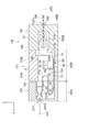
- the front-rear dimension L1 from the rear surface 72AR of the downward projection 72A of the retainer front part 70A to the rear-end rear restriction part 74 is larger than the front-rear dimension L2 of the proximal-side regulated part 32 of the terminal 20. Is formed large. Therefore, the base end portion 30 moves in a predetermined movement range (range L1-L2) in the connector front-rear direction with respect to the housing 60 and the retainer 70 in a state where the retainer 70 is fitted to the housing 60 (that is, an assembled state). It is possible. That is, when the electric wire 80 is pulled, the proximal-side regulated portion 32 moves to the rear of the connector as shown in FIG. On the other hand, when the electric wire 80 is pushed in, as shown in FIG. 10, the base end side restricted portion 32 moves forward of the connector.
- the connector 10 includes a terminal 20, a housing 60, and a retainer 70, and the retainer 70 is fitted into the housing 60 that accommodates the terminal 20.
- the terminal 20 has a proximal end portion 30 having a wire connection portion 31 connected to the electric wire 80 and a distal end portion 50 having a contact portion 52 in contact with the connection object 90. As shown in FIG. 3, the distal end portion 50 is prevented from being detached by a combination of the housing 60 and the retainer 70.
- the base end portion 30 is movable in the front-rear direction of the connector, which is the insertion / extraction direction of the connection object 90, with respect to the housing 60 and the retainer 70 in a state where the retainer 70 is fitted to the housing 60 (that is, an assembled state).
- the terminal 20 has a spring portion 40 located between the proximal end portion 30 and the distal end portion 50. For this reason, even if the electric wire 80 is bent so as to pull or push the terminal 20 in the longitudinal direction of the connector due to vibration or impact, the base end portion 30 having the electric wire connection portion 31 is connected to the housing 60 and the retainer 70.
- the base end portion 30 is movable within a predetermined movement range in the connector vertical direction in a state where the retainer 70 is fitted to the housing 60 (that is, an assembled state).
- the influence of the housing 60 and the retainer 70 due to this bending can be reduced.
- the spring portion 40 positioned between the distal end portion 50 and the proximal end portion 30 is not affected by this.
- the range in which the base end portion 30 moves in the vertical direction of the connector is limited within a predetermined range, the plastic deformation of the spring portion 40 is suppressed.
- the base end portion 30 is movable within a predetermined movement range in the left-right direction of the connector in a state where the retainer 70 is fitted to the housing 60 (that is, an assembled state). The For this reason, even if the electric wire 80 is bent so as to move the terminal 20 in the left-right direction of the connector, the influence of the housing 60 and the retainer 70 due to this bending can be reduced. As a result, it is possible to suppress the influence of this bending from reaching the distal end portion 50 via the housing 60 and the retainer 70.
- the spring portion 40 positioned between the distal end portion 50 and the proximal end portion 30 is not affected by this.
- the range in which the base end portion 30 moves in the left-right direction of the connector is limited within a predetermined range, the plastic deformation of the spring portion 40 is suppressed.
- the housing 60 has a tip placement portion (an upper portion of the housing portion 61 in the housing front portion 60A) in which the tip portion 50 of the terminal 20 can be placed, and this tip placement portion (housing front portion).
- the upper portion of the accommodating portion 61 in 60 ⁇ / b> A has a front-end restricting portion (a concave portion 62 of the housing 60) that restricts the movement range of the front-end portion 50 in the connector front direction.
- the retainer 70 has a rear end restricting portion (a front surface 70 ⁇ / b> F of the retainer 70) that restricts the range of movement of the front end portion 50 in the connector rearward direction in a state of being fitted to the housing 60.
- the terminal 20 when assembling the connector 10, the terminal 20 until the distal end portion 50 of the terminal 20 comes into contact with the front end restricting portion (the recessed portion 62 of the housing 60) of the distal end arrangement portion (the upper portion of the housing portion 61 in the housing front portion 60 ⁇ / b> A). Can be temporarily positioned with respect to the housing 60 by pushing in the connector forward direction. Thereafter, the retainer 70 is fitted into the housing 60, whereby the tip 50 of the terminal 20 can be prevented from coming off. Therefore, the connector 10 can be easily assembled.
- the front end restricting portion the recessed portion 62 of the housing 60
- the distal end arrangement portion the upper portion of the housing portion 61 in the housing front portion 60 ⁇ / b> A
- the housing 60 has a bottom portion (a bottom surface 61B of the housing portion 61) that restricts the range of movement of the base end portion 30 in the connector downward direction, which is the fitting direction of the retainer 70, and the fitting direction of the retainer 70.
- a protruding portion 63 as a “contact portion” that restricts the movement range of the base end portion 30 in the connector upward direction, which is the opposite direction.
- the base end portion 30 of the terminal 20 has a lance 36
- the housing 60 has a lance locking hole 64 for locking the lance 36.
- the lance 36 of the base end portion 30 is locked to the lance locking hole 64 of the housing 60 by pushing the terminal 20 into the housing portion 61 of the housing 60 in the forward direction of the connector.
- the range of movement of the base end portion 30 in the connector rearward direction is temporarily limited. Therefore, since the range of movement of the base end portion 30 in the connector rearward direction is limited in a state before the retainer 70 is fitted, the connector 10 can be easily assembled.
- a tapered surface 35 is formed on the base-end-side regulated portion 32 of the terminal 20.
- the retainer 70 has a base end front restricting portion (a rear surface 72AR of the downward projecting portion 72A of the retainer front portion 70A) that limits the movement range of the base end portion 30 in the connector front direction in the assembled state. Yes.
- the spring of the terminal 20 is pushed when the connector 10 is pushed into the accommodating portion 61 of the housing 60 as compared with the aspect in which the housing 60 has a portion that limits the movement range of the proximal end portion 30 in the connector front direction.
- the portion 40 or the like is not caught by the proximal end front restricting portion, and is easily pushed.
- shaft AX1 of the contact part 52 of the terminal 20 is wire connection axis
- shaft of a flexible wiring material connection part is wire connection axis
- shaft AX2 connection axis
- the spring portion 40 extending from the base end portion 30 to the tip end portion 50 includes: The first bent portion 43 and the second straight portion 44 as “folded portions” folded back in the connector rear direction are configured. For this reason, the easiness of deformation of the spring part 40 can be further ensured, and the sliding at the contact can be more effectively suppressed.
- the end portion (first curved portion 43) in the connector front direction of the “folded portion” is the housing portion 61 of the housing front portion 60A in front of the housing middle portion 60B to which the retainer 70 is fitted. Placed in. For this reason, since the full length of the spring part 40 can be set long, it is easy to ensure the ease of deformation of the spring part 40.
- the first bent portion 43 that is the end portion of the folded portion in the front direction of the connector is present on the front side of the connector with respect to the contact point P (see FIG. 3) in the contact portion 52 of the terminal 20. The movement of the base end 30 is very easily absorbed by the deformation of 40. Furthermore, in this embodiment, as shown in FIG.
- the end portion (second bent portion 45) of the “folded portion” of the terminal 20 in the connector rear direction is between the pair of side wall surfaces 71 ⁇ / b> S of the spring portion arranging groove 71. Placed in. That is, the end portion (second bent portion 45) of the “folded portion” of the terminal 20 in the connector rear direction is arranged in the housing portion 61 in the housing middle portion 60B. For this reason, since the full length of the spring part 40 can be set still longer, it is easy to ensure the ease of deformation
- the protruding portion 63 is formed on the housing 60, and the protruding portion 63 is the base end portion 30 in the counter-fitting direction (connector upward direction) that is opposite to the fitting direction of the retainer 70.
- the protruding portion 63 may not be formed on the housing 60, and a “contact portion” that restricts the range of movement of the proximal end portion 30 in the connector upward direction may be formed on the retainer 70.
- the connector 110 has an object (“flexible wiring material”) connected to one end side (connector rear side) of the terminal 120 as an electric wire. It is different from the above-described embodiment in that it is FPC 180 (“flat wiring material”) instead of 80. In relation to this difference, the base end portion 30 and the like of the terminal 120 are different from the connector 10 according to the above-described embodiment. In other embodiments, unlike the above-described embodiments, the FPC 180 as a “flexible wiring material” and a “flat wiring material” can be inserted into and removed from the assembled connector 110 (FIG. 15). And FIG. 16).
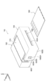
- the connector 110 includes a plurality (six) of terminals 120, a housing 160, a retainer 170, and a cover 190.
- the terminal 120 is accommodated in the housing 160 (see FIG. 13), and then the retainer 170 is fitted into the housing 160 that accommodates the terminal 120 (see FIG. 14) and the cover 190 is assembled, whereby the connector 110 is assembled. Assembled (see FIG. 15).
- the six terminals 120 have the same configuration. One of the six terminals 120 is shown in FIGS. Hereinafter, the terminal 120 will be described.
- the terminal 120 is formed by, for example, bending after a plate material is punched.
- the material of the terminal 120 is, for example, a conductive material such as a copper alloy.
- the terminal 120 has a proximal end portion 30 on one end side, a distal end portion 50 on the other end side, and a spring portion 40 positioned between the distal end portion 50 and the proximal end portion 30.
- the base end portion 30 extends forward from the rear end 20 ⁇ / b> B of the terminal 120.
- the base end portion 30 has an FPC connection portion 131 and a base end side restricted portion 32 in this order from one end side to the other end side.
- the FPC connection portion 131 is a portion connected to the FPC 180 as a “flexible wiring material” and corresponds to the “flexible wiring material connection portion” of the present invention.
- the FPC connecting portion 131 has a contact portion 131A that contacts the FPC 180 (see FIG. 18), and a displacement portion 131B that displaces the position contacting the FPC 180 to the middle side in the connector vertical direction from the proximal-side regulated portion 32. is doing.
- the FPC connection part 131 has its plate thickness direction in the connector width direction.
- the other end side (front end side) of the FPC connection portion 131 is connected to a right side plate portion 34 (one of the pair of side plate portions 34) of the base end side restricted portion 32 described later.
- the FPC connecting portion 131 and the right side plate portion 34 are located on the same plane.
- the contact portions 131A are formed as a pair and come into contact with the FPC 180 so as to be sandwiched from both sides.
- the proximal-side regulated portion 32 is a portion for restricting the movement range of the proximal end portion 30 by contacting the housing 160 and the retainer 170.
- the proximal-side regulated portion 32 has a U shape in which a cross-sectional shape orthogonal to the terminal front-rear direction is opened upward. That is, the base-side regulated portion 32 includes a bottom plate portion 33 extending in the width direction, a right plate portion 34 extending upward from the right end portion of the bottom plate portion 33, and a left plate extending upward from the left end portion of the bottom plate portion 33. Part 34.
- the right side plate portion 34 and the left side plate portion 34 of the base end side restricted portion 32 may be collectively referred to as a pair of side plate portions 34 of the base end side restricted portion 32.
- the side plate part 34 has a front surface 34F facing forward, an upper surface 34U facing upward, and a rear surface 34R facing rearward. Further, a tapered surface 35 is formed between the front surface 34F and the upper surface 34U and faces forward and upward in an oblique direction. Further, the side plate portion 34 has a second upper surface 34U2 facing upward. The second upper surface 34U2 is formed so as to be connected to the lower end of the rear surface 34R, and is positioned below and behind the upper surface 34U.
- a lance 36 is formed on the bottom plate portion 33 of the base end side restricted portion 32.
- the lance 36 is formed by bending the center portion in the width direction of the bottom plate portion 33 downward (outer surface side in the plate thickness direction).
- the spring part 40 has the 1st linear part 41, the inclination part 42, the 1st curved part 43, the 2nd linear part 44, and the 2nd curved part 45 in this order toward the other end side from the one end side. Since the spring part 40 has the same structure as the spring part 40 of the terminal 20 in the above-described embodiment, the description thereof is omitted.
- the distal end portion 50 includes a distal end side restricted portion 51 and a contact portion 52.
- the tip side restricted portion 51 is a portion for restricting the movement range of the tip portion 50 by contacting the housing 160 and the retainer 170. Since the tip portion 50 has the same structure as the spring portion 50 of the terminal 20 in the above-described embodiment, the description thereof is omitted.
- the housing 160 is formed in a substantially rectangular parallelepiped shape by an insulator such as synthetic resin.
- the housing 160 has an accommodating portion 161 that accommodates the terminal 120.
- a plurality of accommodating portions 161 are formed (six in this embodiment corresponding to the number of terminals 120).
- the six accommodating portions 161 have the same configuration as each other, and are formed at equal intervals along the housing width direction.
- the terminal 120 can be accommodated in the accommodating portion 161 by pushing the terminal 120 forward from the rear of the housing 160.
- the housing 160 has a rear portion 160B (housing rear portion 160B, see FIG. 19) formed with a substantially rectangular retainer fitting port 160BH that opens upward from the housing.
- the retainer insertion opening 160BH is connected to the six accommodating portions 61. Therefore, in the housing rear portion 160B, the ceiling surface 61T (see FIG. 19) of the accommodating portion 161 does not exist.
- the pair of left and right side wall surfaces 61S are formed lower than the left and right side walls 60S of the housing 160. Further, the side wall surface 61S of the housing rear portion 160B is interrupted at an intermediate position in the front-rear direction of the housing rear portion 160B. That is, when the housing rear portion 160B is further divided into the front side and the rear side, the side wall surface 61S is formed on the rear side of the housing rear portion 160B, but the side wall surface 61S is not formed on the front side of the housing rear portion 160B. As shown in FIG.
- the base-side regulated portion 32 of the terminal 120 is disposed between the pair of left and right side wall surfaces 61S of the housing rear portion 160B (the accommodating portion 161 in the housing rear portion 160B).
- a displacement portion 131B of the FPC connection portion 131 of the terminal 120 is disposed in the housing portion 61 in the housing rear portion 160B.
- the plurality of accommodating portions 161 are separated from each other. That is, as shown in FIG. 19, in the housing front portion 160A, a pair of left and right side wall surfaces 61S is formed from the bottom surface 61B to the ceiling surface 61T for each accommodating portion 161. As shown in FIGS. 18 and 19, a part of the spring portion 40 of the terminal 120 (for example, the first curved portion) is interposed between the pair of left and right side wall surfaces 61S in the housing front portion 160A (the accommodating portion 61 in the housing front portion 60A). 43) and the tip 50 are arranged.
- the distance between the pair of left and right side wall surfaces 61 ⁇ / b> S is formed to be smaller than the width dimension of the front end side restricted portion 51.
- a recess 62 is formed in the front part 60A of the housing adjacent to the housing middle part 60B and in the vicinity of the ceiling surface 61T to increase the distance between the pair of left and right side wall surfaces 61S. Yes.
- the recesses 62 are formed on both the pair of left and right side wall surfaces 61 ⁇ / b> S, and a pair of left and right sides are formed for each storage portion 61.
- the distance between the pair of left and right recesses 62 is formed to be equal to or larger than the width dimension of the tip-side restricted portion 51 of the terminal 120. Further, the vertical dimension of the recess 62 is formed to be the same as or larger than the vertical dimension of the front end side restricted portion 51.
- the front-rear dimension of the recess 62 is formed to be the same as or larger than the front-rear dimension of the front end side restricted part 51. For this reason, in a state where the front end side restricted portion 51 is pushed forward into the concave portion 62, the front end side restricted portion 51 does not protrude into the housing intermediate portion 60B (the portion where the retainer fitting port 60BH is formed). It has become.
- the upper portion of the accommodating portion 61 in the housing front portion 160 ⁇ / b> A is the tip arrangement portion (the housing front portion) where the tip portion 50 of the terminal 120 is arranged.
- the upper portion of the accommodating portion 161 in the portion 160A) and the lower portion become a spring arrangement portion (a lower portion of the accommodating portion 161 in the housing front portion 160A) in which a part of the spring portion 40 is disposed.
- the second bent portion 45 of the spring portion 40 is disposed in the accommodating portion 161 in the housing rear portion 160B.
- a terminal insertion port 61F is formed on the front side of the tip arrangement portion (the upper portion of the housing portion 161 in the housing front portion 160A).
- the terminal insertion port 61F passes through the front wall of the housing 160 that separates the external space in front of the housing 160 and the accommodating portion 161 in the front-rear direction, and the cross-sectional shape orthogonal to the front-rear direction of the housing is rectangular.
- a tapered portion 61FA is formed that gradually expands in the vertical and horizontal directions toward the front side of the housing.
- the rearward movement range of the tip 50 is not limited by the housing 160.
- the proximal-side regulated portion 32 is disposed near the front end between the pair of left and right side wall surfaces 61S of the housing rear portion 160B. Note that the pair of left and right side wall surfaces 61S of the housing rear portion 160B is not formed with a protruding portion 63 (see FIG. 6) as a “contact portion”.
- the range of movement of the base end 30 in the connector upward direction is not limited.
- a lance locking hole 64 is formed at a position of the bottom surface 61B of the accommodating portion 161 where the proximal-side regulated portion 32 is disposed.
- the lance locking hole 64 is formed so as to penetrate the bottom surface 61 ⁇ / b> B, and locks the lance 36 of the base end portion 30 of the terminal 120.
- the retainer 170 is formed with a plurality (six corresponding to the number of terminals 120) of spring portion arranging grooves 171 whose depth direction is the retainer upper direction.
- the spring portion arranging grooves 171 respectively extend in the front-rear direction of the retainer, and are formed at equal intervals in the retainer width direction.
- the pair of side wall surfaces 71S of the spring portion arranging groove 171 functions similarly to the pair of side wall surfaces 61S of the accommodating portion 161 in a state where the retainer 170 is fitted (see FIG. 19).
- the second curved portion 45 of the terminal 120 is disposed between the pair of side wall surfaces 71 ⁇ / b> S of the spring portion disposition groove 171 with the retainer 170 fitted. .
- the width dimension of the spring part arrangement groove 171 is larger than the width dimension of the spring part 40 of the terminal 120 and smaller than the width dimension of the distal-side regulated part 51 and the proximal-side regulated part 32. .
- the bottom surface 71B of the spring portion arranging groove 171 functions similar to the ceiling surface 61T of the accommodating portion 161 in a state where the retainer 170 is fitted (see FIG. 19). As shown in FIG. 19, in a state where the retainer 170 is fitted, the bottom surface 71B of the spring portion disposition groove 171 is disposed at a position lower than the ceiling surface 61T of the housing front portion 60A.
- the front surface 70F of the retainer 170 is disposed behind the right plate portion 51R, the left plate portion 51L, and the upper plate portion 51T in the distal-side regulated portion 51.
- the retainer 170 has seven downward projecting portions 172 separated by six spring portion arrangement grooves 171.
- the front portion 170A (retainer front portion 170A) of the retainer 170 is disposed in a portion of the housing rear portion 160B where the side wall surface 61S is not formed. Therefore, the downward protrusion 72A of the retainer front portion 170A is formed long downward.
- the lower end of the downward projecting portion 72 is in contact with or close to the bottom surface 61B of the accommodating portion 161 in the retainer front portion 170A.
- a tapered portion 73 whose width dimension and vertical dimension are gradually reduced is formed.
- the retainer rear portion 170B is disposed in a portion of the housing rear portion 160B where the side wall surface 61S is formed. Therefore, the downward projecting portion 72B of the retainer rear portion 170B is formed with a smaller downward projecting amount than the retainer front portion 170A.
- a base end rear restricting portion 74 is further projected downward.
- the rear end restricting portion 74 is disposed behind the pair of side plate portions 34 in the base end side restricted portion 32 of the terminal 120.
- proximal-side rear regulating portion 74 is disposed above the second upper surface 34U2 of the pair of side plate portions 34 in the proximal-side regulated portion 32 of the terminal 120.
- the second upper surfaces 34U2 of the pair of left and right side plate portions 34 of the proximal end side restricted portion 32 are proximal ends. It contacts the rear restricting portion 74 from below. That is, the range of movement of the proximal end portion 30 in the connector upward direction is limited by the rear end restricting portion 74 of the retainer 170. That is, in the present embodiment, the rear end restricting portion 74 of the retainer 170 functions as a “contact portion” that restricts the movement range of the proximal end portion 30 in the counter-fitting direction of the retainer 170. That is, in this embodiment, not the housing 160 but the retainer 170 has the “contact portion”. Of course, in the present embodiment, a protrusion 63 (see FIG. 3 and the like) as a “contact portion” may be formed on the housing 160.
- the base end portion 30 is movable within a predetermined movement range in the connector front-rear direction with respect to the housing 160 and the retainer 170 in a state where the retainer 170 is fitted to the housing 160.
- ⁇ Cover 190> Next, the cover 190 will be described. As shown in FIGS. 14 and 15, a cover 190 is attached to the housing 160 from the rear side. At this time, the locked portions 190SA formed on the left and right side walls 190S of the cover 190 are locked to the protruding locking portions 60SB formed on the left and right side walls 60S of the housing 160.
- the upper surface 190U, the lower surface 190B, the left and right side surfaces 190S, and the rear surface 190R of the cover 190 constitute the outer surface of the connector 110 at the rear part of the connector 110 in the assembled state, as shown in FIGS.
- the upper surface 190U and the lower surface 190B of the cover 190 are substantially flush with the upper and lower surfaces of the housing 160 and the retainer 170.
- the left and right side surfaces 190S of the cover 190 have a step with respect to the left and right side walls 60S of the housing 160.
- the cover 190 has a flat wiring material insertion hole 192 into which the FPC 180 is inserted.
- a taper 192A for guiding the FPC 180 is formed vertically and horizontally.
- the cover 190 has a terminal accommodating portion 193 that accommodates the FPC connecting portions 131 of the plurality of terminals 120.
- the terminal accommodating part 193 is open toward the front.
- the cover 190 has a plurality (five) of partition walls 194 that separate the FPC connection portions 131 of the plurality (six) of terminals 120 from each other.
- the partition wall 194 is formed with a flat wiring material arrangement groove 194A for arranging the FPC 180.
- the connector 110 includes a terminal 120, a housing 160, and a retainer 170, and the retainer 170 is fitted into the housing 160 that accommodates the terminal 120.
- the terminal 120 has a proximal end portion 30 having an FPC connection portion 131 that is connected to the FPC 180, and a distal end portion 50 having a contact portion 52 that is in contact with the connection object 90. As shown in FIG. 18, the distal end portion 50 is prevented from being detached by a combination of the housing 160 and the retainer 170.
- the base end portion 30 is movable in the connector front-rear direction, which is the insertion / extraction direction of the connection object 90, with respect to the housing 160 and the retainer 170 in a state where the retainer 170 is fitted to the housing 160 (that is, an assembled state).
- the terminal 120 has a spring portion 40 located between the proximal end portion 30 and the distal end portion 50. For this reason, even if the FPC 180 is bent so as to pull or push the terminal 120 in the longitudinal direction of the connector due to vibration or impact, the proximal end portion 30 having the FCP connection portion 131 is not connected to the housing 160 and the retainer 170 in the longitudinal direction of the connector.
- the spring portion 40 is suppressed from being plastically deformed.
- Connector 20 Terminal 30 Base End 31 Electric Wire Connection (Flexible Wiring Material Connection) 40 Spring part 43 First curved part (turned part) 44 Second straight part (turned part) 50 Front end portion 52 Contact portion 60 Housing 60BH Retainer fitting port 61 Housing portion 61B Bottom surface (bottom portion) of housing portion 62 Concave part (front end restricting part) 63 Protruding part (contact part) 70 Front of retainer 70F (rear end restriction part) The rear surface of the downward projecting part of the 72AR retainer front part (base end front restricting part) 74 Rear end restricting portion 80 Electric wire (wiring material having flexibility) 90 Connection object AX1 Insertion / extraction axis AX2 Electric wire connection axis (connection axis of flexible wiring material connection part) 110 Connector 120 Terminal 131 FPC connection part (flexible wiring material connection part) 160 Housing 170 Retainer 180 FPC (wiring material having flexibility) 190 Cover
Landscapes
- Connector Housings Or Holding Contact Members (AREA)
Abstract
L'invention concerne un connecteur 10 comprenant : une borne 20 connectée de manière électroconductrice à un objet 90 à connecter, qui est inséré et extrait; un boîtier 60 pour contenir la borne 20; et un dispositif de retenue 70 monté sur le boîtier 60 ayant la borne 20 contenue à l'intérieur de celui-ci. La borne 20 comporte : une section d'extrémité de base 30 ayant une section de connexion de câble électrique 31 (section de connexion de matériau de câblage flexible) connectée à un câble électrique 80 (matériau de câblage flexible); une section d'extrémité avant 50 ayant une section de contact 52 venant en contact avec l'objet 90 à connecter; et une section élastique 40 située entre la section d'extrémité de base 30 et la section d'extrémité avant 50. La section d'extrémité de base 30 peut se déplacer dans une plage de déplacement prédéterminée dans la direction avant et arrière du connecteur tandis que le dispositif de retenue 70 est monté sur le boîtier 60, la direction avant et arrière étant la direction dans laquelle l'objet 90 à connecter est inséré dans le boîtier 60 et extrait de celui-ci.
Priority Applications (4)
| Application Number | Priority Date | Filing Date | Title |
|---|---|---|---|
| JP2019517564A JPWO2018207651A1 (ja) | 2017-05-09 | 2018-04-26 | コネクタ |
| CN201880030002.1A CN110651400A (zh) | 2017-05-09 | 2018-04-26 | 连接器 |
| EP18799119.5A EP3624276A4 (fr) | 2017-05-09 | 2018-04-26 | Connecteur |
| US16/611,164 US20200083632A1 (en) | 2017-05-09 | 2018-04-26 | Connector |
Applications Claiming Priority (2)
| Application Number | Priority Date | Filing Date | Title |
|---|---|---|---|
| JP2017092783 | 2017-05-09 | ||
| JP2017-092783 | 2017-05-09 |
Publications (1)
| Publication Number | Publication Date |
|---|---|
| WO2018207651A1 true WO2018207651A1 (fr) | 2018-11-15 |
Family
ID=64105291
Family Applications (1)
| Application Number | Title | Priority Date | Filing Date |
|---|---|---|---|
| PCT/JP2018/017104 Ceased WO2018207651A1 (fr) | 2017-05-09 | 2018-04-26 | Connecteur |
Country Status (5)
| Country | Link |
|---|---|
| US (1) | US20200083632A1 (fr) |
| EP (1) | EP3624276A4 (fr) |
| JP (1) | JPWO2018207651A1 (fr) |
| CN (1) | CN110651400A (fr) |
| WO (1) | WO2018207651A1 (fr) |
Cited By (1)
| Publication number | Priority date | Publication date | Assignee | Title |
|---|---|---|---|---|
| JP2023061409A (ja) * | 2021-10-20 | 2023-05-02 | 矢崎総業株式会社 | コネクタ |
Families Citing this family (1)
| Publication number | Priority date | Publication date | Assignee | Title |
|---|---|---|---|---|
| CN116325375B (zh) | 2020-08-21 | 2026-04-21 | 日本端子株式会社 | 连接器 |
Citations (4)
| Publication number | Priority date | Publication date | Assignee | Title |
|---|---|---|---|---|
| JP2001126800A (ja) * | 1999-10-22 | 2001-05-11 | Sumitomo Wiring Syst Ltd | 端子金具 |
| JP2010049844A (ja) * | 2008-08-19 | 2010-03-04 | Sumitomo Wiring Syst Ltd | コネクタ及び端子金具 |
| JP2014186934A (ja) | 2013-03-25 | 2014-10-02 | Sumitomo Wiring Syst Ltd | ジョイントコネクタ |
| JP2017092783A (ja) | 2015-11-12 | 2017-05-25 | 株式会社フジクラ | 共振器アンテナ装置 |
Family Cites Families (11)
| Publication number | Priority date | Publication date | Assignee | Title |
|---|---|---|---|---|
| JP2527144Y2 (ja) * | 1992-11-19 | 1997-02-26 | モレックス インコーポレーテッド | プリント回路基板接続用電気コネクタ |
| JPH09106854A (ja) * | 1995-10-13 | 1997-04-22 | Yazaki Corp | 防水コネクタ用雌端子及び樹脂充填防水コネクタ |
| JP2001015213A (ja) * | 1999-06-28 | 2001-01-19 | Yazaki Corp | 半嵌合検知コネクタ |
| US7241190B2 (en) * | 2001-11-20 | 2007-07-10 | Fci Americas Technology, Inc. | Female electrical terminal and electrical connector comprising the same |
| US7112105B2 (en) * | 2003-07-22 | 2006-09-26 | Hon Hai Precision Ind. Co., Ltd. | Cable assembly having power contacts |
| JP2006073271A (ja) * | 2004-08-31 | 2006-03-16 | Tyco Electronics Amp Kk | 電気コネクタ |
| JP2010067432A (ja) * | 2008-09-10 | 2010-03-25 | Sumitomo Wiring Syst Ltd | コネクタ |
| CN102088136A (zh) * | 2009-12-03 | 2011-06-08 | 泰科电子(上海)有限公司 | 电连接端子 |
| JP5747102B1 (ja) * | 2014-04-18 | 2015-07-08 | 日本航空電子工業株式会社 | 雌型コンタクト及び電源用コネクタ |
| JP5907300B1 (ja) * | 2015-04-30 | 2016-04-26 | 第一精工株式会社 | 導電端子 |
| JP6123004B1 (ja) * | 2016-06-10 | 2017-04-26 | イリソ電子工業株式会社 | コネクタ |
-
2018
- 2018-04-26 WO PCT/JP2018/017104 patent/WO2018207651A1/fr not_active Ceased
- 2018-04-26 CN CN201880030002.1A patent/CN110651400A/zh active Pending
- 2018-04-26 US US16/611,164 patent/US20200083632A1/en not_active Abandoned
- 2018-04-26 JP JP2019517564A patent/JPWO2018207651A1/ja active Pending
- 2018-04-26 EP EP18799119.5A patent/EP3624276A4/fr not_active Withdrawn
Patent Citations (4)
| Publication number | Priority date | Publication date | Assignee | Title |
|---|---|---|---|---|
| JP2001126800A (ja) * | 1999-10-22 | 2001-05-11 | Sumitomo Wiring Syst Ltd | 端子金具 |
| JP2010049844A (ja) * | 2008-08-19 | 2010-03-04 | Sumitomo Wiring Syst Ltd | コネクタ及び端子金具 |
| JP2014186934A (ja) | 2013-03-25 | 2014-10-02 | Sumitomo Wiring Syst Ltd | ジョイントコネクタ |
| JP2017092783A (ja) | 2015-11-12 | 2017-05-25 | 株式会社フジクラ | 共振器アンテナ装置 |
Non-Patent Citations (1)
| Title |
|---|
| See also references of EP3624276A4 * |
Cited By (3)
| Publication number | Priority date | Publication date | Assignee | Title |
|---|---|---|---|---|
| JP2023061409A (ja) * | 2021-10-20 | 2023-05-02 | 矢崎総業株式会社 | コネクタ |
| JP7408611B2 (ja) | 2021-10-20 | 2024-01-05 | 矢崎総業株式会社 | コネクタ |
| US12327952B2 (en) | 2021-10-20 | 2025-06-10 | Yazaki Corporation | Electrical connector with retaining member |
Also Published As
| Publication number | Publication date |
|---|---|
| JPWO2018207651A1 (ja) | 2020-03-12 |
| CN110651400A (zh) | 2020-01-03 |
| EP3624276A1 (fr) | 2020-03-18 |
| EP3624276A4 (fr) | 2021-01-13 |
| US20200083632A1 (en) | 2020-03-12 |
Similar Documents
| Publication | Publication Date | Title |
|---|---|---|
| JP6816668B2 (ja) | コネクタ | |
| CN104283028A (zh) | 扁平导体用电连接器 | |
| US6482035B2 (en) | Press-connecting connector | |
| JP5238481B2 (ja) | 電気コネクタ | |
| JP5098875B2 (ja) | コネクタ | |
| JP2002313472A (ja) | コネクタ | |
| JP2006179266A (ja) | コネクタ | |
| CN110323613B (zh) | 连接器及端子零件 | |
| JP2010135147A (ja) | 分割コネクタ | |
| KR20000017090A (ko) | 커넥터의 하우징 및 그것에 의해 제조된 커넥터 | |
| WO2018207651A1 (fr) | Connecteur | |
| US7654865B2 (en) | Electrical connector | |
| JP6317844B1 (ja) | コネクタ | |
| JP4488372B2 (ja) | ケーブル用電気コネクタ | |
| JP2011018538A (ja) | ガタつき防止機能付きコネクタ | |
| JP7014139B2 (ja) | コネクタ | |
| CN118073886A (zh) | 连接器 | |
| JP5217602B2 (ja) | コネクタ | |
| JP7389407B2 (ja) | カードエッジコネクタ | |
| JP5986933B2 (ja) | 端子 | |
| JP6937081B2 (ja) | コネクタ | |
| JP2002033149A (ja) | コネクタ | |
| JP3800314B2 (ja) | コネクタ | |
| JP5394696B2 (ja) | コネクタ | |
| JP2013045735A (ja) | ケーブル用電気コネクタおよび電気コネクタ組立体 |
Legal Events
| Date | Code | Title | Description |
|---|---|---|---|
| 121 | Ep: the epo has been informed by wipo that ep was designated in this application |
Ref document number: 18799119 Country of ref document: EP Kind code of ref document: A1 |
|
| ENP | Entry into the national phase |
Ref document number: 2019517564 Country of ref document: JP Kind code of ref document: A |
|
| NENP | Non-entry into the national phase |
Ref country code: DE |
|
| ENP | Entry into the national phase |
Ref document number: 2018799119 Country of ref document: EP Effective date: 20191209 |