EP3624330A1 - Motorsteuerungsvorrichtung - Google Patents
Motorsteuerungsvorrichtung Download PDFInfo
- Publication number
- EP3624330A1 EP3624330A1 EP19196176.2A EP19196176A EP3624330A1 EP 3624330 A1 EP3624330 A1 EP 3624330A1 EP 19196176 A EP19196176 A EP 19196176A EP 3624330 A1 EP3624330 A1 EP 3624330A1
- Authority
- EP
- European Patent Office
- Prior art keywords
- processing circuit
- task
- output
- periodic
- system microcomputer
- Prior art date
- Legal status (The legal status is an assumption and is not a legal conclusion. Google has not performed a legal analysis and makes no representation as to the accuracy of the status listed.)
- Granted
Links
Images

Classifications
-
- H—ELECTRICITY
- H02—GENERATION; CONVERSION OR DISTRIBUTION OF ELECTRIC POWER
- H02P—CONTROL OR REGULATION OF ELECTRIC MOTORS, ELECTRIC GENERATORS OR DYNAMO-ELECTRIC CONVERTERS; CONTROLLING TRANSFORMERS, REACTORS OR CHOKE COILS
- H02P27/00—Arrangements or methods for the control of AC motors characterised by the kind of supply voltage
- H02P27/04—Arrangements or methods for the control of AC motors characterised by the kind of supply voltage using variable-frequency supply voltage, e.g. inverter or converter supply voltage
- H02P27/06—Arrangements or methods for the control of AC motors characterised by the kind of supply voltage using variable-frequency supply voltage, e.g. inverter or converter supply voltage using DC to AC converters or inverters
-
- B—PERFORMING OPERATIONS; TRANSPORTING
- B62—LAND VEHICLES FOR TRAVELLING OTHERWISE THAN ON RAILS
- B62D—MOTOR VEHICLES; TRAILERS
- B62D5/00—Power-assisted or power-driven steering
- B62D5/04—Power-assisted or power-driven steering electrical, e.g. using an electric servo-motor connected to, or forming part of, the steering gear
- B62D5/0457—Power-assisted or power-driven steering electrical, e.g. using an electric servo-motor connected to, or forming part of, the steering gear characterised by control features of the drive means as such
- B62D5/046—Controlling the motor
- B62D5/0463—Controlling the motor calculating assisting torque from the motor based on driver input
-
- H—ELECTRICITY
- H02—GENERATION; CONVERSION OR DISTRIBUTION OF ELECTRIC POWER
- H02M—APPARATUS FOR CONVERSION BETWEEN AC AND AC, BETWEEN AC AND DC, OR BETWEEN DC AND DC, AND FOR USE WITH MAINS OR SIMILAR POWER SUPPLY SYSTEMS; CONVERSION OF DC OR AC INPUT POWER INTO SURGE OUTPUT POWER; CONTROL OR REGULATION THEREOF
- H02M1/00—Details of apparatus for conversion
- H02M1/14—Arrangements for reducing ripples from DC input or output
- H02M1/143—Arrangements for reducing ripples from DC input or output using compensating arrangements
-
- H—ELECTRICITY
- H02—GENERATION; CONVERSION OR DISTRIBUTION OF ELECTRIC POWER
- H02P—CONTROL OR REGULATION OF ELECTRIC MOTORS, ELECTRIC GENERATORS OR DYNAMO-ELECTRIC CONVERTERS; CONTROLLING TRANSFORMERS, REACTORS OR CHOKE COILS
- H02P1/00—Arrangements for starting electric motors or dynamo-electric converters
- H02P1/16—Arrangements for starting electric motors or dynamo-electric converters for starting dynamo-electric motors or dynamo-electric converters
- H02P1/54—Arrangements for starting electric motors or dynamo-electric converters for starting dynamo-electric motors or dynamo-electric converters for starting two or more dynamo-electric motors
-
- H—ELECTRICITY
- H02—GENERATION; CONVERSION OR DISTRIBUTION OF ELECTRIC POWER
- H02P—CONTROL OR REGULATION OF ELECTRIC MOTORS, ELECTRIC GENERATORS OR DYNAMO-ELECTRIC CONVERTERS; CONTROLLING TRANSFORMERS, REACTORS OR CHOKE COILS
- H02P21/00—Arrangements or methods for the control of electric machines by vector control, e.g. by control of field orientation
- H02P21/22—Current control, e.g. using a current control loop
-
- H—ELECTRICITY
- H02—GENERATION; CONVERSION OR DISTRIBUTION OF ELECTRIC POWER
- H02P—CONTROL OR REGULATION OF ELECTRIC MOTORS, ELECTRIC GENERATORS OR DYNAMO-ELECTRIC CONVERTERS; CONTROLLING TRANSFORMERS, REACTORS OR CHOKE COILS
- H02P23/00—Arrangements or methods for the control of AC motors characterised by a control method other than vector control
- H02P23/14—Estimation or adaptation of motor parameters, e.g. rotor time constant, flux, speed, current or voltage
-
- H—ELECTRICITY
- H02—GENERATION; CONVERSION OR DISTRIBUTION OF ELECTRIC POWER
- H02P—CONTROL OR REGULATION OF ELECTRIC MOTORS, ELECTRIC GENERATORS OR DYNAMO-ELECTRIC CONVERTERS; CONTROLLING TRANSFORMERS, REACTORS OR CHOKE COILS
- H02P25/00—Arrangements or methods for the control of AC motors characterised by the kind of AC motor or by structural details
- H02P25/16—Arrangements or methods for the control of AC motors characterised by the kind of AC motor or by structural details characterised by the circuit arrangement or by the kind of wiring
- H02P25/22—Multiple windings; Windings for more than three phases
-
- H—ELECTRICITY
- H02—GENERATION; CONVERSION OR DISTRIBUTION OF ELECTRIC POWER
- H02P—CONTROL OR REGULATION OF ELECTRIC MOTORS, ELECTRIC GENERATORS OR DYNAMO-ELECTRIC CONVERTERS; CONTROLLING TRANSFORMERS, REACTORS OR CHOKE COILS
- H02P5/00—Arrangements specially adapted for regulating or controlling the speed or torque of two or more electric motors
-
- H—ELECTRICITY
- H02—GENERATION; CONVERSION OR DISTRIBUTION OF ELECTRIC POWER
- H02P—CONTROL OR REGULATION OF ELECTRIC MOTORS, ELECTRIC GENERATORS OR DYNAMO-ELECTRIC CONVERTERS; CONTROLLING TRANSFORMERS, REACTORS OR CHOKE COILS
- H02P6/00—Arrangements for controlling synchronous motors or other dynamo-electric motors using electronic commutation dependent on the rotor position; Electronic commutators therefor
- H02P6/10—Arrangements for controlling torque ripple, e.g. providing reduced torque ripple
-
- H—ELECTRICITY
- H02—GENERATION; CONVERSION OR DISTRIBUTION OF ELECTRIC POWER
- H02M—APPARATUS FOR CONVERSION BETWEEN AC AND AC, BETWEEN AC AND DC, OR BETWEEN DC AND DC, AND FOR USE WITH MAINS OR SIMILAR POWER SUPPLY SYSTEMS; CONVERSION OF DC OR AC INPUT POWER INTO SURGE OUTPUT POWER; CONTROL OR REGULATION THEREOF
- H02M1/00—Details of apparatus for conversion
- H02M1/0003—Details of control, feedback or regulation circuits
- H02M1/0029—Circuits or arrangements for limiting the slope of switching signals, e.g. slew rate
-
- H—ELECTRICITY
- H02—GENERATION; CONVERSION OR DISTRIBUTION OF ELECTRIC POWER
- H02P—CONTROL OR REGULATION OF ELECTRIC MOTORS, ELECTRIC GENERATORS OR DYNAMO-ELECTRIC CONVERTERS; CONTROLLING TRANSFORMERS, REACTORS OR CHOKE COILS
- H02P2207/00—Indexing scheme relating to controlling arrangements characterised by the type of motor
- H02P2207/07—Doubly fed machines receiving two supplies both on the stator only wherein the power supply is fed to different sets of stator windings or to rotor and stator windings
- H02P2207/076—Doubly fed machines receiving two supplies both on the stator only wherein the power supply is fed to different sets of stator windings or to rotor and stator windings wherein both supplies are made via converters: especially doubly-fed induction machines; e.g. for starting
-
- H—ELECTRICITY
- H02—GENERATION; CONVERSION OR DISTRIBUTION OF ELECTRIC POWER
- H02P—CONTROL OR REGULATION OF ELECTRIC MOTORS, ELECTRIC GENERATORS OR DYNAMO-ELECTRIC CONVERTERS; CONTROLLING TRANSFORMERS, REACTORS OR CHOKE COILS
- H02P29/00—Arrangements for regulating or controlling electric motors, appropriate for both AC and DC motors
- H02P29/02—Providing protection against overload without automatic interruption of supply
- H02P29/024—Detecting a fault condition, e.g. short circuit, locked rotor, open circuit or loss of load
- H02P29/028—Detecting a fault condition, e.g. short circuit, locked rotor, open circuit or loss of load the motor continuing operation despite the fault condition, e.g. eliminating, compensating for or remedying the fault
Definitions
- the present invention relates to a motor control device that controls a motor including a first stator coil and a second stator coil which are insulated from each other.
- the motor control device operates a first drive circuit connected to the first stator coil and a second drive circuit connected to the second stator coil.
- JP 2017-158230 A describes a control device provided with separate microprocessor units (MPUs) (processing circuits) for controlling current flowing in each of two stator coils which are isolated from each other. More specifically, when controlling the current flowing in the stator coils, the two processing circuits detect a difference in their control timings and finely adjust their control timings to reduce the difference.
- MPUs microprocessor units
- a second processing circuit continues the control of the current.
- the reset first processing circuit is reactivated, a phenomenon in which the operations of the two processing circuits can not be synchronized occurs.
- An object of the present invention is to provide a motor control device that can solve the above phenomenon.
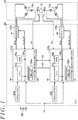
- a motor 10 shown in FIG. 1 serves as a power source in a steering operation actuator used for steering steered wheels.
- the motor 10 is provided with a rotor 12 and a pair of stator coils including an A system stator coil 14a and a B system stator coil 14b.
- a control device 20 controls the motor 10 by controlling torque that is a controlled variable of the motor 10.
- the control device 20 includes a circuit of system A and a circuit of system B, which correspond to the A system stator coil 14a and the B system stator coil 14b, respectively.
- control device 20 includes the following as the circuit of system A: an A system inverter 22a connected to the A system stator coil 14a; an A system microcomputer 30a that controls current flowing in the A system stator coil 14a by outputting an operation signal MSa to the A system inverter 22a; and an A system oscillator 24a that outputs an external clock signal to the A system microcomputer 30a.
- the control device 20 includes the following as the circuit of system B: a B system inverter 22b connected to the B system stator coil 14b; a B system microcomputer 30b that controls current flowing in the B system stator coil 14b by outputting an operation signal MSb to the B system inverter 22b; and a B system oscillator 24b that outputs an external clock signal to the B system microcomputer 30b. Terminal voltage of a battery 50 is applied to the A system microcomputer 30a, the A system inverter 22a, the B system microcomputer 30b, and the B system inverter 22b.
- the A system microcomputer 30a acquires a rotation angle ⁇ a of the rotor 12 detected by an A system angle sensor 40a and three-phase currents iua, iva, and iwa flowing in the A system stator coil 14a.
- the currents iua, iva, and iwa may be detected as, for example, a voltage drop of a shunt resistor connected to each leg of the A system inverter 22a.
- the B system microcomputer 30b acquires a rotation angle ⁇ b of the rotor 12 detected by a B system angle sensor 40b and three-phase currents iub, ivb, iwb flowing in the B system stator coil 14b.
- the currents iub, ivb and iwb may be detected as, for example, a voltage drop of a shunt resistor connected to each leg of the B system inverter 22b.
- a mark "#” is used.
- expressions such as “# system inverter 22# is connected to # system stator coil 14#” is used. That is, the mark “#” represents upper cases A, B when placed before the term "system”, and lower cases a, b when placed after symbols such as numbers and alphabets.
- the # system microcomputer 30# is provided with a central processing unit (CPU) 32#, a read only memory (ROM) 34#, a peripheral circuit 36# and the like, which are connected via a bus line 38#.
- the peripheral circuit 36# includes a circuit that generates a clock signal defining an internal operation based on the external clock signal, a power supply circuit, a reset circuit, and the like.
- the reset circuit is a circuit that resets the microcomputer 30# (CPU 32#) when the voltage applied to the # system microcomputer 30# (CPU 32#) falls outside a voltage range that can guarantee the operation of the # system microcomputer 30# (CPU 32 #).
- the # system microcomputer 30# controls the current flowing in the # system stator coil 14# in order to control the torque of the motor 10 based on steering torque Th that is the torque input from a steering wheel.
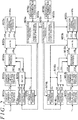
- FIG. 2 shows processing executed by the A system microcomputer 30a and the B system microcomputer 30b.
- the processing shown in FIG. 2 is achieved by the CPU 32# executing a program stored in the ROM 34#.
- the mark "#" is used.
- a torque command value calculation process M10# is a process of calculating a torque command value T#* that indicates a torque required of the motor 10 to assist the driver's steering operation based on the steering torque Th.
- the torque of the motor 10 is controlled to its required value by cooperation of the currents flowing in the A system stator coil 14a and the B system stator coil 14b. That is, when both of the A system microcomputer 30a and the B system microcomputer 30b perform current control, a sum of a torque command value Ta* and a torque command value Tb* is the torque required of the motor 10.
- a current command value calculation process M12# is a process of calculating current command values id#*, iq#*, which are command values of the current flowing in the # system stator coil 14#, so as to control the torque of the motor 10 in accordance with the torque command value T#*.
- a current acquisition process M14# is a process of acquiring currents iu#, iv#, and iw# flowing in the # system stator coil 14#.
- a dq conversion process M16# is a process of converting the three-phase currents iu#, iv#, and iw# into dq-axis currents id#, iq#.
- a feedback process M18# is a process of calculating dq-axis voltages vd#, vq# as operation variables for feedback control to cause the dq-axis currents id#, iq# to follow the current command values id#*, iq#*.
- a three-phase conversion process M20# is a process of converting the dq-axis voltages vd#, vq# into three-phase voltages vu#, vv#, and vw#.
- An operation signal generation process M22# is a process of outputting an operation signal MS# to the # system inverter 22# such that the voltage of each phase applied to the # system stator coil 14# by the # system inverter 22# becomes the voltages vu#, vv#, and vw#.
- the operation signal MS# here is an on/off operation signal of each switching element of the # system inverter 22#.
- the operation signal generation process M22# includes a process of calculating the operation signal MS# by triangular wave pulse width modulation (PWM) processing.
- PWM triangular wave pulse width modulation
- An angle acquisition process M24# is a process of acquiring a rotation angle ⁇ # detected by # system angle sensor 42# and outputting the acquired rotation angle ⁇ # to the dq conversion process M16# or the three-phase conversion process M20#.
- An abnormality determination process M26# is a process of determining whether there is an abnormality in the operation of the # system microcomputer 30#.
- the abnormality determination process M26# includes a process of determining that the operation is abnormal when there is an abnormality in the process of controlling the current flowing in the # system stator coil 14# by the # system microcomputer 30#. Since the control of the current flowing in the # system stator coil 14# has not started when the # system microcomputer 30# is activated, the abnormality determination process M26# determines that there is an abnormality.
- a synchronization process M28# is a process of synchronizing the operations of the current acquisition process M14#, the angle acquisition process M24#, and the operation signal generation process M22# based on the internal clock signal.
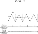
- FIG. 3 shows an example of operations of the current acquisition process M14#, the angle acquisition process M24#, and the operation signal generation process M22#.
- the operation signal MS# is generated based on comparison in magnitude between a carrier Sc in a triangular wave shape and the voltages vu#, vv#, and vw# shown in FIG. 3 .
- FIG. 3 only the voltage vu# of the U phase is shown as an example.
- the current acquisition process M14# is executed in the same cycle as the cycle of the carrier Sc.
- the angle acquisition process M24# is executed at a cycle longer than the cycle of the carrier Sc.
- the cycles of periodic tasks executed by the # system microcomputer 30# such as task 1 and task 2 are all multiples of the cycle of the internal clock signal.
- task 1 has the shortest cycle among the cycles of the periodic tasks executed by both the A system microcomputer 30a and the B system microcomputer 30b.
- all the cycles of the periodic tasks executed by the # system microcomputer 30# are divisors of the longest cycle among all the cycles.
- the synchronization process M28# includes a periodic signal output process M30#.
- the periodic signal output process M30# is a process of outputting a synchronization signal synchronized with a cycle of a task with the shortest cycle, among the periodic tasks executed by both the A system microcomputer 30a and the B system microcomputer 30b, via a communication line 44 shown in FIG. 1 .
- the abnormality determination process M26# determines that there is an abnormality
- the periodic signal output process M30# stops outputting the synchronization signal.
- the synchronization process M28# includes a process of synchronizing execution of periodical tasks between system A and system B via the communication line 44.
- the first reason is to suppress torque ripple. That is, for example, when the execution timing of task 1 differs between system A and system B, the update timing of the operation signal MSa of system A and the execution timing of task 1 of system B may become close to each other. In this case, noise resulting from the ringing of the currents iua, iva, and iwa flowing in the A system stator coil 14a may be superimposed on the currents iub, ivb, and iwb acquired in the current acquisition process M14b.
- the execution timing of task 2 differs between system A and system B, even if the currents iub, ivb, and iwb and the currents iua, iva, and iwa are equal to each other, the voltages vua, wa, and vwa and the voltages vub, wb, and vwb may differ from each other because the rotation angles ⁇ a, ⁇ b used differ from each other.
- the second reason for synchronizing the execution of periodical tasks in system A and system B is because tasks for executing bi-directional communication via a serial line 42 shown in FIG. 1 , for example, requires that system A and system B be synchronized.
- the execution timings of all periodic tasks can be synchronized by synchronizing the execution timings of the task having the longest cycle, among the periodic tasks executed by both the A system microcomputer 30a and the B system microcomputer 30b.
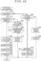
- FIG. 4A shows a procedure of a synchronization process M28a
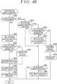
- FIG. 4B shows a procedure of a synchronization process M28b.
- the processes shown in FIGS. 4A and 4B are achieved by the CPU 32# repeatedly executing a program stored in the ROM 34# whenever, for example, a predetermined execution condition is satisfied.
- a step number of each process is expressed as a number preceded by the letter S.
- the processes shown in FIGS. 4A and 4B will be described according to a time series of events that may actually occur from the time of activation of the control device 20.
- a CPU 32a first determines whether the A system microcomputer 30a is activated (S10). Since the A system microcomputer 30a is activated when the control device 20 is activated, the CPU 32a determines that the A system microcomputer 30a is activated (S10: YES), and determines whether the B system microcomputer 30b is operating normally (S12). This process is a process of determining that the B system microcomputer 30b is operating normally when a periodic signal is output by a periodic signal output process M30b on the B system microcomputer 30b side.
- the B system microcomputer 30b Since the B system microcomputer 30b is activated when the control device 20 is activated, control of the current flowing in the B system stator coil 14b is not yet performed in the B system microcomputer 30b, and an abnormality determination process M26b determines this as an abnormality. As a result, the process of outputting the periodic signal by the periodic signal output process M30b is prohibited. Therefore, the CPU 32a determines that the operation of the B system microcomputer 30b is not normal (S12: NO), and sets the status of the A system microcomputer 30a as a master (S14).
- the CPU 32b first determines whether the B system microcomputer 30b is activated (S40). Since the B system microcomputer 30b is activated when the control device 20 is activated, the CPU 32b determines that the B system microcomputer 30b is activated (S40: YES), and sets the status of the B system microcomputer 30b as a slave (S42). Next, the CPU 32b determines whether the A system microcomputer 30a is operating normally (S44). This process is a process of determining that the A system microcomputer 30a is operating normally when the periodic signal is output by the periodic signal output process M30a on the A system microcomputer 30a side.
- the CPU 32b determines that the operation of the A system microcomputer 30a is not normal (S44: NO). As soon as preparation for periodically executing each task on the B system microcomputer 30b side is completed, the CPU 32b executes a completion output process to output a notification of preparation completion for notifying that preparation has been completed via the communication line 44 (S46).
- the CPU 32a stands by until the notification of preparation completion is received (S16: NO). Upon receiving the notification of preparation completion (S16: YES), the CPU 32a executes a synchronization output process of outputting, via the communication line 44, the synchronization signal synchronized with the execution timing, in the A system microcomputer 30a, of the task having the longest cycle among the periodic tasks executed by both the A system microcomputer 30a and the B system microcomputer 30b (S 18). At this time, the CPU 32a starts periodic task execution.
- the CPU 32b upon receiving the synchronization signal (S48), the CPU 32b starts, based on the received synchronization signal, periodical execution of each task in the B system microcomputer 30b such that the execution timing of each periodic task is synchronized with that on the A system microcomputer 30a side (S50).
- control of the current flowing in the A system stator coil 14a by the A system microcomputer 30a and control of the current flowing in the B system stator coil 14b by the B system microcomputer 30b are performed.
- the CPU 32b determines whether the status of the B system microcomputer 30b is the master (S52). Upon determining that the status of the B system microcomputer 30b is the slave (S52: NO), the CPU 32b determines whether the A system microcomputer 30a is operating normally (S54).
- the CPU 32b Upon determining that the A system microcomputer 30a is operating normally (S54: YES), the CPU 32b receives the periodic signal output from the A system microcomputer 30a (S56). Then, based on the periodic signal, the CPU 32b corrects the execution timing of the task on the B system microcomputer 30b side as needed, thereby executing a process to approximate the execution timing of the task on the B system microcomputer 30b side to the execution timing of the task on the A system microcomputer 30a side (S58). Specifically, the CPU 32a appropriately corrects the execution timing by a time that is an integral multiple of the cycle of the internal clock, regarding one cycle of the internal clock as a minimum unit.
- the following description involves, for example, a case where the terminal voltage of the battery 50 decreases and only the voltage applied to the B system microcomputer 30b falls below the operation guarantee voltage due to factors such as individual differences in the resistance value of the electric path between system A and system B, so that the B system microcomputer 30b is reset.
- the B system microcomputer 30b is reactivated by a rise in the applied voltage to some extent.
- the CPU 32b determines that the B system microcomputer 30b is activated (S40: YES), and after executing the process of S42, determines whether the A system microcomputer 30a is operating normally (S44).
- S40 YES
- S42 determines whether the A system microcomputer 30a is operating normally
- S44 determines whether the A system microcomputer 30a is operating normally
- the CPU 32b determines that the A system microcomputer 30a is operating normally (S44: YES), and executes a synchronization request process that outputs, via the communication line 44, a request signal for requesting the A system microcomputer 30a to output the synchronization signal (S60).
- the CPU 32a determines that the A system microcomputer 30a is not activated (S10: NO), and determines whether the status of the A system microcomputer 30a is the master (S20). Upon determining that the status of the A system microcomputer 30a is the master (S20: YES), the CPU 32a determines whether a request signal has been received (S22).
- the CPU 32a Upon determining that the request signal has been received (S22: YES), the CPU 32a executes a resynchronization output process to output, via the communication line 44, a synchronization signal synchronized with the execution timing, in the A system microcomputer 30a, of the task having the longest cycle among the periodic tasks executed by both the A system microcomputer 30a and the B system microcomputer 30b (S24).
- the CPU 32b receives the synchronization signal output by the resynchronization output process (S48), and executes the process of S50 based on this synchronization signal.
- the following description involves, for example, a case where the terminal voltage of the battery 50 decreases and only the voltage applied to the A system microcomputer 30a falls below the operation guarantee voltage due to factors such as individual differences in the resistance value of the electric path between system A and system B, so that the A system microcomputer 30a is reset.
- the A system microcomputer 30a is reactivated by the rise in the applied voltage to some extent.
- the CPU 32a determines that the A system microcomputer 30a is activated (S10: YES), and determines whether the B system microcomputer 30b is operating normally (S12).
- S10: YES the A system microcomputer 30a is activated
- S12 the B system microcomputer 30b is operating normally
- the CPU 32a determines that the B system microcomputer 30b is operating normally (S12: YES), and sets the status of the A system microcomputer 30a as the slave (S26).
- the CPU 32a executes a synchronization request process of outputting a request signal for requesting the B system microcomputer 30b to output the synchronization signal via the communication line 44 (S28).
- the CPU 32b determines whether the status of the B system microcomputer 30b is the master (S52). Upon determining that the status of the B system microcomputer 30b is the slave (S52: NO), the CPU 32b determines whether the A system microcomputer 30a is operating normally (S54). Upon determining that the A system microcomputer 30a is not operating normally (S54: NO), the CPU 32b sets the status of the B system microcomputer 30b as the master (S62).
- the CPU 32b determines whether a request signal has been received (S64). Upon determining that the request signal has been received (S64: YES), the CPU 32b executes a resynchronization output process to output, via the communication line 44, the synchronization signal synchronized with the execution timing, in the B system microcomputer 30b, of the task having the longest cycle among the periodic tasks executed by both the A system microcomputer 30a and the B system microcomputer 30b (S66).
- the CPU 32b upon receiving the synchronization signal (S30), the CPU 32b starts, based on the received synchronization signal, periodical execution of each task in the A system microcomputer 30a such that the execution timing of each periodic task is synchronized with that on the B system microcomputer 30b side (S32). Thereafter, the CPU 32a determines that the status of the A system microcomputer 30a is the slave (S20: NO), and receives the periodic signal output from the B system microcomputer 30b (S34).
- the CPU 32a corrects the execution timing of the task on the A system microcomputer 30a side as needed, thereby executing a process to approximate the execution timing of the task on the A system microcomputer 30a side to the execution timing of the task on the B system microcomputer 30b side (S36).
- the CPU 32a When completing the processes of S18, S24, S32, and S36, or making a negative determination in the process of S22, the CPU 32a temporarily ends the series of processes shown in FIG. 4A . Meanwhile, when completing the processes of S50, S58, and S66, or making a negative determination in the process of S64, the CPU 32b temporarily ends the processes shown in FIG. 4B .
- FIG. 5 shows a case where only the B system microcomputer 30b is reset after the control device 20 is activated.
- the CPU 32b outputs the request signal to the A system microcomputer 30a at time t1.
- the CPU 32a After receiving the request signal, the CPU 32a outputs the synchronization signal synchronized with the execution timing of the task n having the longest cycle, among the periodic tasks executed by both the A system microcomputer 30a and the B system microcomputer 30b. That is, even if the execution timings of task 1, task 2, etc. arrive, the CPU 32a stands by without outputting the synchronization signal until the execution timing of task n arrives.
- the CPU 32a outputs the synchronization signal upon arrival of the execution timing of task n, that is, the execution timing of all periodic tasks.
- the execution timing of task n is the latest one of the execution timings of the periodic tasks appearing after the reception of the request signal. In other words, the execution timings of all periodic tasks appear at or before the appearance of the execution timing of task n after the reception of the request signal.
- the CPU 32b With the output of the synchronization signal synchronized with the execution timing of task n, the CPU 32b synchronizes the execution timing of all periodic tasks with the synchronization signal. Note that synchronizing the execution timings of all periodic tasks with the synchronization signal does not mean that the execution timings of multiple periodic tasks having the same cycle coincide with each other.
- tasks whose execution timings synchronize with the synchronization signal may include not only tasks executed immediately after reception of the synchronization signal, but also tasks executed after a predetermined amount of time has elapsed from reception of the synchronization signal.
- the relationship between the matters described above in the present embodiment and the matters described above in the SUMMARY OF THE INVENTION is as follows. In the following, the relationship is described based on each solution number in the SUMMARY OF THE INVENTION. [1] The following cases 1 and 2 will be described separately.
- the first stator coil, the first drive circuit, and the first processing circuit correspond to the A system stator coil 14a, the A system inverter 22a, and the A system microcomputer 30a, respectively.
- the first stator coil, the first drive circuit, and the first processing circuit correspond to the B system stator coil 14b, the B system inverter 22b, and the B system microcomputer 30b, respectively.
- the synchronization request process corresponds to the process of S28, and the resynchronization output process corresponds to the process of S66.
- the synchronization request process corresponds to the process of S60, and the resynchronization output process corresponds to the process of S24.
- the periodic signal output process corresponds to the periodic signal output process M30b, and the correction process corresponds to the process of S36.
- the periodic signal output process corresponds to the periodic signal output process M30a, and the correction process corresponds to the process of S58.
- the solution corresponds only to case 1.
- the completion output process corresponds to the process of S46, and the synchronization output process corresponds to the process of S18.
- the solution corresponds only to case 1.
- the periodic signal output process corresponds to the periodic signal output process M30a
- the correction process corresponds to the process of S58.
- the first task corresponds to the current acquisition processes M14a and M14b
- the second task corresponds to the angle acquisition processes M24a and M24b.
- the first current acquisition process and the second current acquisition process respectively correspond to the current acquisition process M14a and the current acquisition process M14b
- the first angle acquisition process and the second angle acquisition process respectively correspond to the angle acquisition process M24a and the angle acquisition process M24b
- the first current control process and the second current acquisition process correspond to feedback processes M18a and M18b, the three-phase conversion processes M20a and M20b, and operation signal generation processes M22a and M22b.
- At least one of the matters of the embodiment may be changed as follows.
- the cycles of the periodic tasks executed by both the A system microcomputer 30a and the B system microcomputer 30b are divisors of the longest execution cycle among the periodic tasks.
- the present invention is not limited thereto.
- the execution cycle is not a divisor of the cycle of the task having the longest execution cycle, although the cycles of all tasks are multiples of the cycle of the internal clock signal.
- the periodic signal corresponding to the cycle of the task having the shortest execution cycle among the tasks executed by both the A system microcomputer 30a and the B system microcomputer 30b is output.
- the present invention is not limited thereto.
- a periodic signal corresponding to a cycle of a task having an intermediate execution cycle between the task having the shortest execution cycle and the task having the longest execution cycle may be output.
- the periodic signal output process is constantly executed regardless of whether the status of the microcomputer is the master or the slave.
- the present invention is not limited thereto.
- the periodic signal output process may be executed only in the microcomputer whose status is the master.
- the synchronization signal when one of the A system microcomputer 30a and the B system microcomputer 30b receives the synchronization request signal, the synchronization signal synchronized with the execution timing of the task having the longest execution cycle, among the periodic tasks executed by both the A system microcomputer 30a and the B system microcomputer 30b, is output.
- the present invention is not limited thereto.
- the synchronization signal may be output at a timing that corresponds to an execution timing of the task having the longest execution cycle and is synchronized with the least common multiple of the cycles of all the periodic tasks.
- the synchronization signal may be output at a timing synchronized with the cycle of the least common multiple of the cycle of the bidirectional communication process via the serial line 42, the cycle of the angle acquisition process M24#, and the cycle of the current acquisition process M14#, as well as the execution timing of the current acquisition process M14#.
- a periodic signal corresponding to a task having an intermediate execution cycle when a periodic signal corresponding to a task having an intermediate execution cycle is output, it is desirable to output a synchronization signal synchronized with the execution timing of a task having a longer execution cycle than the task corresponding to the periodic signal.
- a task whose execution cycle is longer than the cycle of the task corresponding to the periodic signal executed by the A system microcomputer 30a and a task whose execution cycle is longer than the cycle of the task corresponding to the periodic signal executed by the B system microcomputer 30b can be synchronized.
- the feedback process M18#, the three-phase conversion process M20#, and the operation signal generation process M22# are exemplified as the current control process for controlling the current flowing in the stator coil to follow the command value.
- the present invention is not limited thereto.
- model predictive control may be performed to select an actual switching mode based on the difference between the predicted value and the command value of the current that is output in the case where the switching mode of the inverter is variously set based on the current flowing in the stator coil. Even in this case, it is desirable to make the update cycle of the rotation angle used to calculate the predicted value longer than the update cycle of the switching mode or the current.
- the A system microcomputer 30a is determined as the master by default, and the B system microcomputer 30b is used as the master only when the A system microcomputer 30a recovers from its reset state while the B system microcomputer 30b is operating normally.
- the present invention is not limited thereto.
- one of the A system microcomputer 30a and the B system microcomputer 30b that has been the master immediately before the stop of the A system microcomputer 30a and the B system microcomputer 30b may become the master when activated thereafter. This can be achieved, for example, by providing each of the A system microcomputer 30a and the B system microcomputer 30b with an electrically rewritable non-volatile memory, and storing the status in the non-volatile memory.
- the status may be fixed such that, for example, the A system microcomputer 30a is the master and the B system microcomputer 30b is the slave. In this case, even if the A system microcomputer 30a recovers from its reset state and is activated while the B system microcomputer 30b continues its normal operation, the B system microcomputer 30b may receive a periodic signal of the A system microcomputer 30a and may execute a correction process to correct the execution cycle of its own task. Note that when the A system microcomputer 30a recovers from its reset state while the B system microcomputer 30b is operating normally, the A system microcomputer 30a outputs a synchronization request signal to the B system microcomputer 30b.
- the peripheral circuit 36# includes the reset circuit, the present invention is not limited thereto.
- the reset circuit may be provided outside the # system microcomputer 30#, and the reset voltage of the reset circuit may be applied to the # system microcomputer 30#.
- the ROM is exemplified as a program storage device constituting the processing circuit, and the type of the ROM is not specified.
- a non-rewritable memory or an electrically rewritable non-volatile memory may be used.
- the program storage device is not limited to the ROM.
- the processing circuit is not limited to a software processing circuit including a program storage device storing a program and a CPU executing the program, and may be a dedicated hardware circuit such as an application specific integrated circuit (ASIC) that executes predetermined processing.
- ASIC application specific integrated circuit
- the three-phase inverter has been exemplified as the drive circuit, but the present invention is not limited thereto.
- a direct current (DC) motor may be used as the motor and an H bridge circuit may be used as the drive circuit.
- DC direct current
- the control device may include three or more stator coils, three or more drive circuits, and three or more processing circuits, to provide a providing system C in addition to system A and system B, for example.
- the control device may include three or more stator coils, three or more drive circuits, and three or more processing circuits, to provide a providing system C in addition to system A and system B, for example.
- This can be achieved by a simple change in the processes shown in FIGS. 4A and 4B by, for example, setting a priority for the master. That is, for example, assuming that the priority for the master is set in the order of system A, system B, and system C, when system A is reset while system B and system C are operating normally, system B becomes the master.
- the sensor for detecting the rotation angle of the motor 10 is not limited to the rotation angle sensors separately provided for each system, and may be, for example, a single rotation angle sensor. In the embodiment described above, the sensor for detecting the steering torque Th is not particularly mentioned. The sensors may differ from one another for each system, and alternatively, the detection value of a single sensor may be shared between the systems.
Landscapes
- Engineering & Computer Science (AREA)
- Power Engineering (AREA)
- Chemical & Material Sciences (AREA)
- Combustion & Propulsion (AREA)
- Transportation (AREA)
- Mechanical Engineering (AREA)
- Control Of Ac Motors In General (AREA)
- Control Of Motors That Do Not Use Commutators (AREA)
Applications Claiming Priority (1)
| Application Number | Priority Date | Filing Date | Title |
|---|---|---|---|
| JP2018169463A JP7115168B2 (ja) | 2018-09-11 | 2018-09-11 | モータの制御装置 |
Publications (2)
| Publication Number | Publication Date |
|---|---|
| EP3624330A1 true EP3624330A1 (de) | 2020-03-18 |
| EP3624330B1 EP3624330B1 (de) | 2025-12-31 |
Family
ID=67902378
Family Applications (1)
| Application Number | Title | Priority Date | Filing Date |
|---|---|---|---|
| EP19196176.2A Active EP3624330B1 (de) | 2018-09-11 | 2019-09-09 | Motorsteuerungsvorrichtung |
Country Status (4)
| Country | Link |
|---|---|
| US (1) | US10879784B2 (de) |
| EP (1) | EP3624330B1 (de) |
| JP (1) | JP7115168B2 (de) |
| CN (1) | CN110890858B (de) |
Cited By (1)
| Publication number | Priority date | Publication date | Assignee | Title |
|---|---|---|---|---|
| EP4050792A1 (de) * | 2021-02-26 | 2022-08-31 | Kabushiki Kaisha Yaskawa Denki | Stromwandlungsvorrichtung, steuersystem, antriebssystem und stromwandlungsverfahren |
Families Citing this family (7)
| Publication number | Priority date | Publication date | Assignee | Title |
|---|---|---|---|---|
| JP7280099B2 (ja) * | 2019-04-19 | 2023-05-23 | 株式会社ジェイテクト | モータの制御システム、およびモータの制御装置 |
| JP2021069249A (ja) * | 2019-10-28 | 2021-04-30 | ルネサスエレクトロニクス株式会社 | 半導体装置及びモータ制御方法 |
| CN112821814B (zh) * | 2021-01-27 | 2022-08-12 | 湖南大学 | 一种降低位置同步波动的多舵机同步控制方法及系统 |
| JP7697863B2 (ja) * | 2021-10-15 | 2025-06-24 | 株式会社ジェイテクト | 車両用制御装置 |
| CN114448293B (zh) * | 2022-04-06 | 2022-07-05 | 中汽创智科技有限公司 | 电机同步控制方法、系统、车辆及存储介质 |
| CN116540614B (zh) * | 2023-07-04 | 2023-11-03 | 深圳砺驰半导体科技有限公司 | 信号控制方法、装置及电子设备 |
| GB2701648A (en) * | 2024-10-25 | 2026-05-06 | Evolito Ltd | Electric propulsion unit |
Citations (3)
| Publication number | Priority date | Publication date | Assignee | Title |
|---|---|---|---|---|
| US20150214864A1 (en) * | 2014-01-30 | 2015-07-30 | Deere & Company | Control synchronization between multiple control units for resource load sharing |
| JP2017158230A (ja) | 2016-02-29 | 2017-09-07 | 株式会社ジェイテクト | モータ制御装置 |
| EP3264591A1 (de) * | 2015-02-24 | 2018-01-03 | Mitsubishi Electric Corporation | Elektrische antriebsvorrichtung und elektrische servolenkvorrichtung |
Family Cites Families (7)
| Publication number | Priority date | Publication date | Assignee | Title |
|---|---|---|---|---|
| JP2003033075A (ja) * | 2001-07-10 | 2003-01-31 | Hitachi Ltd | 同期モータ制御装置および電気自動車 |
| CN100418298C (zh) * | 2005-03-23 | 2008-09-10 | 比亚迪股份有限公司 | 一种永磁同步电机转子位置传感方法和位置传感装置 |
| JP5538649B2 (ja) * | 2010-09-24 | 2014-07-02 | 三菱電機株式会社 | 回転機の制御装置 |
| US10267819B2 (en) * | 2016-02-04 | 2019-04-23 | GM Global Technology Operations LLC | Method and apparatus to monitor a resolver |
| DE112017003491B4 (de) * | 2016-07-11 | 2022-01-20 | Denso Corporation | Motorsteuerungsvorrichtung, Motorantriebssystem und Motorsteuerungsverfahren |
| JP6911561B2 (ja) * | 2016-07-11 | 2021-07-28 | 株式会社デンソー | モータ制御装置、モータ駆動システム、及び、モータ制御方法 |
| JP6801287B2 (ja) * | 2016-08-10 | 2020-12-16 | 株式会社ジェイテクト | モータ制御装置 |
-
2018
- 2018-09-11 JP JP2018169463A patent/JP7115168B2/ja active Active
-
2019
- 2019-09-06 US US16/562,909 patent/US10879784B2/en active Active
- 2019-09-06 CN CN201910841987.2A patent/CN110890858B/zh active Active
- 2019-09-09 EP EP19196176.2A patent/EP3624330B1/de active Active
Patent Citations (3)
| Publication number | Priority date | Publication date | Assignee | Title |
|---|---|---|---|---|
| US20150214864A1 (en) * | 2014-01-30 | 2015-07-30 | Deere & Company | Control synchronization between multiple control units for resource load sharing |
| EP3264591A1 (de) * | 2015-02-24 | 2018-01-03 | Mitsubishi Electric Corporation | Elektrische antriebsvorrichtung und elektrische servolenkvorrichtung |
| JP2017158230A (ja) | 2016-02-29 | 2017-09-07 | 株式会社ジェイテクト | モータ制御装置 |
Cited By (2)
| Publication number | Priority date | Publication date | Assignee | Title |
|---|---|---|---|---|
| EP4050792A1 (de) * | 2021-02-26 | 2022-08-31 | Kabushiki Kaisha Yaskawa Denki | Stromwandlungsvorrichtung, steuersystem, antriebssystem und stromwandlungsverfahren |
| US12113450B2 (en) | 2021-02-26 | 2024-10-08 | Kabushiki Kaisha Yaskawa Denki | Power conversion device |
Also Published As
| Publication number | Publication date |
|---|---|
| JP7115168B2 (ja) | 2022-08-09 |
| US10879784B2 (en) | 2020-12-29 |
| EP3624330B1 (de) | 2025-12-31 |
| JP2020043692A (ja) | 2020-03-19 |
| CN110890858B (zh) | 2024-07-19 |
| CN110890858A (zh) | 2020-03-17 |
| US20200083797A1 (en) | 2020-03-12 |
Similar Documents
| Publication | Publication Date | Title |
|---|---|---|
| EP3624330B1 (de) | Motorsteuerungsvorrichtung | |
| US10654518B2 (en) | Motor control apparatus, motor drive system, and motor control method | |
| EP3264591B1 (de) | Elektrische antriebsvorrichtung und elektrische servolenkvorrichtung | |
| JP3664040B2 (ja) | モータ制御用pwmインバータ | |
| EP3388280A1 (de) | Fahrzeugsteuerungssystem umfassend synchronisierte steuerungsschaltungen | |
| JP2017163789A (ja) | モータ駆動装置及びモータ駆動装置における相電流検出方法 | |
| US9018872B2 (en) | Motor control circuit | |
| JP6662721B2 (ja) | 制御装置、モータ制御装置、及び電動パワーステアリング装置 | |
| JP2020175820A (ja) | モータの制御システム、およびモータの制御装置 | |
| JP2002029432A (ja) | 電動パワーステアリング制御装置 | |
| EP3709503A1 (de) | Steuerung für einen motor | |
| EP3964424B1 (de) | Vorrichtung zur steuerung eines motors | |
| KR100313970B1 (ko) | 영구자석형동기전동기의제어장치 | |
| US11652429B2 (en) | Motor control apparatus | |
| EP2242174A2 (de) | Steuerungsvorrichtung und Steuerungsverfahren für einen Wechselstrommotor | |
| US11095247B2 (en) | Controller for motor | |
| JP2017195659A (ja) | 電子制御装置及びモータ制御装置 | |
| JP2006081322A (ja) | 交流電動機の制御装置 | |
| CN114157185B (zh) | 控制装置 | |
| CN120604451A (zh) | 马达控制装置、马达控制方法以及马达控制系统 | |
| JP2007252139A (ja) | 電動機制御装置および電動機制御方法 | |
| JP2018113753A (ja) | 交流電動機の制御装置 |
Legal Events
| Date | Code | Title | Description |
|---|---|---|---|
| PUAI | Public reference made under article 153(3) epc to a published international application that has entered the european phase |
Free format text: ORIGINAL CODE: 0009012 |
|
| STAA | Information on the status of an ep patent application or granted ep patent |
Free format text: STATUS: THE APPLICATION HAS BEEN PUBLISHED |
|
| AK | Designated contracting states |
Kind code of ref document: A1 Designated state(s): AL AT BE BG CH CY CZ DE DK EE ES FI FR GB GR HR HU IE IS IT LI LT LU LV MC MK MT NL NO PL PT RO RS SE SI SK SM TR |
|
| AX | Request for extension of the european patent |
Extension state: BA ME |
|
| STAA | Information on the status of an ep patent application or granted ep patent |
Free format text: STATUS: REQUEST FOR EXAMINATION WAS MADE |
|
| 17P | Request for examination filed |
Effective date: 20200824 |
|
| RAP1 | Party data changed (applicant data changed or rights of an application transferred) |
Owner name: JTEKT CORPORATION |
|
| RBV | Designated contracting states (corrected) |
Designated state(s): AL AT BE BG CH CY CZ DE DK EE ES FI FR GB GR HR HU IE IS IT LI LT LU LV MC MK MT NL NO PL PT RO RS SE SI SK SM TR |
|
| RIN1 | Information on inventor provided before grant (corrected) |
Inventor name: SAIJO, MASATO Inventor name: FUJI, MASASHI Inventor name: NIWA, TOMOHIRO Inventor name: TSUJIHASHI, MASATAKA |
|
| STAA | Information on the status of an ep patent application or granted ep patent |
Free format text: STATUS: EXAMINATION IS IN PROGRESS |
|
| 17Q | First examination report despatched |
Effective date: 20210802 |
|
| RAP3 | Party data changed (applicant data changed or rights of an application transferred) |
Owner name: JTEKT CORPORATION |
|
| GRAP | Despatch of communication of intention to grant a patent |
Free format text: ORIGINAL CODE: EPIDOSNIGR1 |
|
| STAA | Information on the status of an ep patent application or granted ep patent |
Free format text: STATUS: GRANT OF PATENT IS INTENDED |
|
| RIC1 | Information provided on ipc code assigned before grant |
Ipc: H02P 5/00 20160101AFI20250731BHEP Ipc: H02P 6/10 20060101ALI20250731BHEP Ipc: H02P 25/22 20060101ALI20250731BHEP Ipc: B62D 5/04 20060101ALI20250731BHEP Ipc: H02P 1/54 20060101ALI20250731BHEP Ipc: H02P 29/028 20160101ALN20250731BHEP |
|
| INTG | Intention to grant announced |
Effective date: 20250820 |
|
| GRAS | Grant fee paid |
Free format text: ORIGINAL CODE: EPIDOSNIGR3 |
|
| GRAA | (expected) grant |
Free format text: ORIGINAL CODE: 0009210 |
|
| STAA | Information on the status of an ep patent application or granted ep patent |
Free format text: STATUS: THE PATENT HAS BEEN GRANTED |
|
| AK | Designated contracting states |
Kind code of ref document: B1 Designated state(s): AL AT BE BG CH CY CZ DE DK EE ES FI FR GB GR HR HU IE IS IT LI LT LU LV MC MK MT NL NO PL PT RO RS SE SI SK SM TR |
|
| REG | Reference to a national code |
Ref country code: CH Ref legal event code: F10 Free format text: ST27 STATUS EVENT CODE: U-0-0-F10-F00 (AS PROVIDED BY THE NATIONAL OFFICE) Effective date: 20251231 Ref country code: GB Ref legal event code: FG4D |
|
| REG | Reference to a national code |
Ref country code: DE Ref legal event code: R096 Ref document number: 602019079754 Country of ref document: DE |
|
| REG | Reference to a national code |
Ref country code: IE Ref legal event code: FG4D |
|
| REG | Reference to a national code |
Ref country code: LT Ref legal event code: MG9D |
|
| PG25 | Lapsed in a contracting state [announced via postgrant information from national office to epo] |
Ref country code: NO Free format text: LAPSE BECAUSE OF FAILURE TO SUBMIT A TRANSLATION OF THE DESCRIPTION OR TO PAY THE FEE WITHIN THE PRESCRIBED TIME-LIMIT Effective date: 20260331 |
|
| PG25 | Lapsed in a contracting state [announced via postgrant information from national office to epo] |
Ref country code: HR Free format text: LAPSE BECAUSE OF FAILURE TO SUBMIT A TRANSLATION OF THE DESCRIPTION OR TO PAY THE FEE WITHIN THE PRESCRIBED TIME-LIMIT Effective date: 20251231 Ref country code: FI Free format text: LAPSE BECAUSE OF FAILURE TO SUBMIT A TRANSLATION OF THE DESCRIPTION OR TO PAY THE FEE WITHIN THE PRESCRIBED TIME-LIMIT Effective date: 20251231 |
|
| PG25 | Lapsed in a contracting state [announced via postgrant information from national office to epo] |
Ref country code: RS Free format text: LAPSE BECAUSE OF FAILURE TO SUBMIT A TRANSLATION OF THE DESCRIPTION OR TO PAY THE FEE WITHIN THE PRESCRIBED TIME-LIMIT Effective date: 20260331 |
|
| PG25 | Lapsed in a contracting state [announced via postgrant information from national office to epo] |
Ref country code: LV Free format text: LAPSE BECAUSE OF FAILURE TO SUBMIT A TRANSLATION OF THE DESCRIPTION OR TO PAY THE FEE WITHIN THE PRESCRIBED TIME-LIMIT Effective date: 20251231 |
|
| PG25 | Lapsed in a contracting state [announced via postgrant information from national office to epo] |
Ref country code: BG Free format text: LAPSE BECAUSE OF FAILURE TO SUBMIT A TRANSLATION OF THE DESCRIPTION OR TO PAY THE FEE WITHIN THE PRESCRIBED TIME-LIMIT Effective date: 20251231 |
|
| REG | Reference to a national code |
Ref country code: NL Ref legal event code: MP Effective date: 20251231 |
|
| REG | Reference to a national code |
Ref country code: AT Ref legal event code: MK05 Ref document number: 1874591 Country of ref document: AT Kind code of ref document: T Effective date: 20251231 |
|
| PG25 | Lapsed in a contracting state [announced via postgrant information from national office to epo] |
Ref country code: NL Free format text: LAPSE BECAUSE OF FAILURE TO SUBMIT A TRANSLATION OF THE DESCRIPTION OR TO PAY THE FEE WITHIN THE PRESCRIBED TIME-LIMIT Effective date: 20251231 |
|
| PG25 | Lapsed in a contracting state [announced via postgrant information from national office to epo] |
Ref country code: LT Free format text: LAPSE BECAUSE OF FAILURE TO SUBMIT A TRANSLATION OF THE DESCRIPTION OR TO PAY THE FEE WITHIN THE PRESCRIBED TIME-LIMIT Effective date: 20251231 |
|
| PG25 | Lapsed in a contracting state [announced via postgrant information from national office to epo] |
Ref country code: SM Free format text: LAPSE BECAUSE OF FAILURE TO SUBMIT A TRANSLATION OF THE DESCRIPTION OR TO PAY THE FEE WITHIN THE PRESCRIBED TIME-LIMIT Effective date: 20251231 |
|
| PG25 | Lapsed in a contracting state [announced via postgrant information from national office to epo] |
Ref country code: ES Free format text: LAPSE BECAUSE OF FAILURE TO SUBMIT A TRANSLATION OF THE DESCRIPTION OR TO PAY THE FEE WITHIN THE PRESCRIBED TIME-LIMIT Effective date: 20251231 |
|
| PG25 | Lapsed in a contracting state [announced via postgrant information from national office to epo] |
Ref country code: PL Free format text: LAPSE BECAUSE OF FAILURE TO SUBMIT A TRANSLATION OF THE DESCRIPTION OR TO PAY THE FEE WITHIN THE PRESCRIBED TIME-LIMIT Effective date: 20251231 |
|
| PG25 | Lapsed in a contracting state [announced via postgrant information from national office to epo] |
Ref country code: IT Free format text: LAPSE BECAUSE OF FAILURE TO SUBMIT A TRANSLATION OF THE DESCRIPTION OR TO PAY THE FEE WITHIN THE PRESCRIBED TIME-LIMIT Effective date: 20251231 |
|
| PG25 | Lapsed in a contracting state [announced via postgrant information from national office to epo] |
Ref country code: AT Free format text: LAPSE BECAUSE OF FAILURE TO SUBMIT A TRANSLATION OF THE DESCRIPTION OR TO PAY THE FEE WITHIN THE PRESCRIBED TIME-LIMIT Effective date: 20251231 |
|
| PG25 | Lapsed in a contracting state [announced via postgrant information from national office to epo] |
Ref country code: EE Free format text: LAPSE BECAUSE OF FAILURE TO SUBMIT A TRANSLATION OF THE DESCRIPTION OR TO PAY THE FEE WITHIN THE PRESCRIBED TIME-LIMIT Effective date: 20251231 |
|
| PG25 | Lapsed in a contracting state [announced via postgrant information from national office to epo] |
Ref country code: IS Free format text: LAPSE BECAUSE OF FAILURE TO SUBMIT A TRANSLATION OF THE DESCRIPTION OR TO PAY THE FEE WITHIN THE PRESCRIBED TIME-LIMIT Effective date: 20260430 Ref country code: PT Free format text: LAPSE BECAUSE OF FAILURE TO SUBMIT A TRANSLATION OF THE DESCRIPTION OR TO PAY THE FEE WITHIN THE PRESCRIBED TIME-LIMIT Effective date: 20260430 |
|
| PG25 | Lapsed in a contracting state [announced via postgrant information from national office to epo] |
Ref country code: CZ Free format text: LAPSE BECAUSE OF FAILURE TO SUBMIT A TRANSLATION OF THE DESCRIPTION OR TO PAY THE FEE WITHIN THE PRESCRIBED TIME-LIMIT Effective date: 20251231 |
|
| PG25 | Lapsed in a contracting state [announced via postgrant information from national office to epo] |
Ref country code: SK Free format text: LAPSE BECAUSE OF FAILURE TO SUBMIT A TRANSLATION OF THE DESCRIPTION OR TO PAY THE FEE WITHIN THE PRESCRIBED TIME-LIMIT Effective date: 20251231 |
|
| PG25 | Lapsed in a contracting state [announced via postgrant information from national office to epo] |
Ref country code: SE Free format text: LAPSE BECAUSE OF FAILURE TO SUBMIT A TRANSLATION OF THE DESCRIPTION OR TO PAY THE FEE WITHIN THE PRESCRIBED TIME-LIMIT Effective date: 20251231 |