EP3624742B1 - Dispositif de fixation d'article médical comprenant un polymère viscoélastique - Google Patents
Dispositif de fixation d'article médical comprenant un polymère viscoélastique Download PDFInfo
- Publication number
- EP3624742B1 EP3624742B1 EP18801835.2A EP18801835A EP3624742B1 EP 3624742 B1 EP3624742 B1 EP 3624742B1 EP 18801835 A EP18801835 A EP 18801835A EP 3624742 B1 EP3624742 B1 EP 3624742B1
- Authority
- EP
- European Patent Office
- Prior art keywords
- polymer film
- securement device
- major surface
- film
- adhesive
- Prior art date
- Legal status (The legal status is an assumption and is not a legal conclusion. Google has not performed a legal analysis and makes no representation as to the accuracy of the status listed.)
- Active
Links
Images

Classifications
-
- A—HUMAN NECESSITIES
- A61—MEDICAL OR VETERINARY SCIENCE; HYGIENE
- A61F—FILTERS IMPLANTABLE INTO BLOOD VESSELS; PROSTHESES; DEVICES PROVIDING PATENCY TO, OR PREVENTING COLLAPSING OF, TUBULAR STRUCTURES OF THE BODY, e.g. STENTS; ORTHOPAEDIC, NURSING OR CONTRACEPTIVE DEVICES; FOMENTATION; TREATMENT OR PROTECTION OF EYES OR EARS; BANDAGES, DRESSINGS OR ABSORBENT PADS; FIRST-AID KITS
- A61F13/00—Bandages or dressings; Absorbent pads
- A61F13/02—Adhesive bandages or dressings
- A61F13/0269—Tapes for dressing attachment
-
- A—HUMAN NECESSITIES
- A61—MEDICAL OR VETERINARY SCIENCE; HYGIENE
- A61M—DEVICES FOR INTRODUCING MEDIA INTO, OR ONTO, THE BODY; DEVICES FOR TRANSDUCING BODY MEDIA OR FOR TAKING MEDIA FROM THE BODY; DEVICES FOR PRODUCING OR ENDING SLEEP OR STUPOR
- A61M25/00—Catheters; Hollow probes
- A61M25/01—Introducing, guiding, advancing, emplacing or holding catheters
- A61M25/02—Holding devices, e.g. on the body
-
- B—PERFORMING OPERATIONS; TRANSPORTING
- B32—LAYERED PRODUCTS
- B32B—LAYERED PRODUCTS, i.e. PRODUCTS BUILT-UP OF STRATA OF FLAT OR NON-FLAT, e.g. CELLULAR OR HONEYCOMB, FORM
- B32B27/00—Layered products comprising a layer of synthetic resin
- B32B27/06—Layered products comprising a layer of synthetic resin as the main or only constituent of a layer, which is next to another layer of the same or of a different material
-
- B—PERFORMING OPERATIONS; TRANSPORTING
- B32—LAYERED PRODUCTS
- B32B—LAYERED PRODUCTS, i.e. PRODUCTS BUILT-UP OF STRATA OF FLAT OR NON-FLAT, e.g. CELLULAR OR HONEYCOMB, FORM
- B32B27/00—Layered products comprising a layer of synthetic resin
- B32B27/06—Layered products comprising a layer of synthetic resin as the main or only constituent of a layer, which is next to another layer of the same or of a different material
- B32B27/08—Layered products comprising a layer of synthetic resin as the main or only constituent of a layer, which is next to another layer of the same or of a different material of synthetic resin
-
- B—PERFORMING OPERATIONS; TRANSPORTING
- B32—LAYERED PRODUCTS
- B32B—LAYERED PRODUCTS, i.e. PRODUCTS BUILT-UP OF STRATA OF FLAT OR NON-FLAT, e.g. CELLULAR OR HONEYCOMB, FORM
- B32B27/00—Layered products comprising a layer of synthetic resin
- B32B27/06—Layered products comprising a layer of synthetic resin as the main or only constituent of a layer, which is next to another layer of the same or of a different material
- B32B27/10—Layered products comprising a layer of synthetic resin as the main or only constituent of a layer, which is next to another layer of the same or of a different material of paper or cardboard
-
- B—PERFORMING OPERATIONS; TRANSPORTING
- B32—LAYERED PRODUCTS
- B32B—LAYERED PRODUCTS, i.e. PRODUCTS BUILT-UP OF STRATA OF FLAT OR NON-FLAT, e.g. CELLULAR OR HONEYCOMB, FORM
- B32B27/00—Layered products comprising a layer of synthetic resin
- B32B27/12—Layered products comprising a layer of synthetic resin next to a fibrous or filamentary layer
-
- B—PERFORMING OPERATIONS; TRANSPORTING
- B32—LAYERED PRODUCTS
- B32B—LAYERED PRODUCTS, i.e. PRODUCTS BUILT-UP OF STRATA OF FLAT OR NON-FLAT, e.g. CELLULAR OR HONEYCOMB, FORM
- B32B27/00—Layered products comprising a layer of synthetic resin
- B32B27/30—Layered products comprising a layer of synthetic resin comprising vinyl (co)polymers; comprising acrylic (co)polymers
- B32B27/304—Layered products comprising a layer of synthetic resin comprising vinyl (co)polymers; comprising acrylic (co)polymers comprising vinyl halide (co)polymers, e.g. PVC, PVDC, PVF, PVDF
-
- B—PERFORMING OPERATIONS; TRANSPORTING
- B32—LAYERED PRODUCTS
- B32B—LAYERED PRODUCTS, i.e. PRODUCTS BUILT-UP OF STRATA OF FLAT OR NON-FLAT, e.g. CELLULAR OR HONEYCOMB, FORM
- B32B27/00—Layered products comprising a layer of synthetic resin
- B32B27/30—Layered products comprising a layer of synthetic resin comprising vinyl (co)polymers; comprising acrylic (co)polymers
- B32B27/308—Layered products comprising a layer of synthetic resin comprising vinyl (co)polymers; comprising acrylic (co)polymers comprising acrylic (co)polymers
-
- B—PERFORMING OPERATIONS; TRANSPORTING
- B32—LAYERED PRODUCTS
- B32B—LAYERED PRODUCTS, i.e. PRODUCTS BUILT-UP OF STRATA OF FLAT OR NON-FLAT, e.g. CELLULAR OR HONEYCOMB, FORM
- B32B27/00—Layered products comprising a layer of synthetic resin
- B32B27/32—Layered products comprising a layer of synthetic resin comprising polyolefins
-
- B—PERFORMING OPERATIONS; TRANSPORTING
- B32—LAYERED PRODUCTS
- B32B—LAYERED PRODUCTS, i.e. PRODUCTS BUILT-UP OF STRATA OF FLAT OR NON-FLAT, e.g. CELLULAR OR HONEYCOMB, FORM
- B32B27/00—Layered products comprising a layer of synthetic resin
- B32B27/34—Layered products comprising a layer of synthetic resin comprising polyamides
-
- B—PERFORMING OPERATIONS; TRANSPORTING
- B32—LAYERED PRODUCTS
- B32B—LAYERED PRODUCTS, i.e. PRODUCTS BUILT-UP OF STRATA OF FLAT OR NON-FLAT, e.g. CELLULAR OR HONEYCOMB, FORM
- B32B27/00—Layered products comprising a layer of synthetic resin
- B32B27/36—Layered products comprising a layer of synthetic resin comprising polyesters
-
- B—PERFORMING OPERATIONS; TRANSPORTING
- B32—LAYERED PRODUCTS
- B32B—LAYERED PRODUCTS, i.e. PRODUCTS BUILT-UP OF STRATA OF FLAT OR NON-FLAT, e.g. CELLULAR OR HONEYCOMB, FORM
- B32B27/00—Layered products comprising a layer of synthetic resin
- B32B27/40—Layered products comprising a layer of synthetic resin comprising polyurethanes
-
- B—PERFORMING OPERATIONS; TRANSPORTING
- B32—LAYERED PRODUCTS
- B32B—LAYERED PRODUCTS, i.e. PRODUCTS BUILT-UP OF STRATA OF FLAT OR NON-FLAT, e.g. CELLULAR OR HONEYCOMB, FORM
- B32B29/00—Layered products comprising a layer of paper or cardboard
- B32B29/002—Layered products comprising a layer of paper or cardboard as the main or only constituent of a layer, which is next to another layer of the same or of a different material
- B32B29/005—Layered products comprising a layer of paper or cardboard as the main or only constituent of a layer, which is next to another layer of the same or of a different material next to another layer of paper or cardboard layer
-
- B—PERFORMING OPERATIONS; TRANSPORTING
- B32—LAYERED PRODUCTS
- B32B—LAYERED PRODUCTS, i.e. PRODUCTS BUILT-UP OF STRATA OF FLAT OR NON-FLAT, e.g. CELLULAR OR HONEYCOMB, FORM
- B32B29/00—Layered products comprising a layer of paper or cardboard
- B32B29/02—Layered products comprising a layer of paper or cardboard next to a fibrous or filamentary layer
-
- B—PERFORMING OPERATIONS; TRANSPORTING
- B32—LAYERED PRODUCTS
- B32B—LAYERED PRODUCTS, i.e. PRODUCTS BUILT-UP OF STRATA OF FLAT OR NON-FLAT, e.g. CELLULAR OR HONEYCOMB, FORM
- B32B3/00—Layered products comprising a layer with external or internal discontinuities or unevennesses, or a layer of non-planar shape; Layered products comprising a layer having particular features of form
- B32B3/02—Layered products comprising a layer with external or internal discontinuities or unevennesses, or a layer of non-planar shape; Layered products comprising a layer having particular features of form characterised by features of form at particular places, e.g. in edge regions
- B32B3/08—Layered products comprising a layer with external or internal discontinuities or unevennesses, or a layer of non-planar shape; Layered products comprising a layer having particular features of form characterised by features of form at particular places, e.g. in edge regions characterised by added members at particular parts
-
- B—PERFORMING OPERATIONS; TRANSPORTING
- B32—LAYERED PRODUCTS
- B32B—LAYERED PRODUCTS, i.e. PRODUCTS BUILT-UP OF STRATA OF FLAT OR NON-FLAT, e.g. CELLULAR OR HONEYCOMB, FORM
- B32B3/00—Layered products comprising a layer with external or internal discontinuities or unevennesses, or a layer of non-planar shape; Layered products comprising a layer having particular features of form
- B32B3/26—Layered products comprising a layer with external or internal discontinuities or unevennesses, or a layer of non-planar shape; Layered products comprising a layer having particular features of form characterised by a particular shape of the outline of the cross-section of a continuous layer; characterised by a layer with cavities or internal voids ; characterised by an apertured layer
- B32B3/266—Layered products comprising a layer with external or internal discontinuities or unevennesses, or a layer of non-planar shape; Layered products comprising a layer having particular features of form characterised by a particular shape of the outline of the cross-section of a continuous layer; characterised by a layer with cavities or internal voids ; characterised by an apertured layer characterised by an apertured layer, the apertures going through the whole thickness of the layer, e.g. expanded metal, perforated layer, slit layer regular cells B32B3/12
-
- B—PERFORMING OPERATIONS; TRANSPORTING
- B32—LAYERED PRODUCTS
- B32B—LAYERED PRODUCTS, i.e. PRODUCTS BUILT-UP OF STRATA OF FLAT OR NON-FLAT, e.g. CELLULAR OR HONEYCOMB, FORM
- B32B5/00—Layered products characterised by the non- homogeneity or physical structure, i.e. comprising a fibrous, filamentary, particulate or foam layer; Layered products characterised by having a layer differing constitutionally or physically in different parts
- B32B5/02—Layered products characterised by the non- homogeneity or physical structure, i.e. comprising a fibrous, filamentary, particulate or foam layer; Layered products characterised by having a layer differing constitutionally or physically in different parts characterised by structural features of a fibrous or filamentary layer
- B32B5/022—Non-woven fabric
-
- B—PERFORMING OPERATIONS; TRANSPORTING
- B32—LAYERED PRODUCTS
- B32B—LAYERED PRODUCTS, i.e. PRODUCTS BUILT-UP OF STRATA OF FLAT OR NON-FLAT, e.g. CELLULAR OR HONEYCOMB, FORM
- B32B5/00—Layered products characterised by the non- homogeneity or physical structure, i.e. comprising a fibrous, filamentary, particulate or foam layer; Layered products characterised by having a layer differing constitutionally or physically in different parts
- B32B5/02—Layered products characterised by the non- homogeneity or physical structure, i.e. comprising a fibrous, filamentary, particulate or foam layer; Layered products characterised by having a layer differing constitutionally or physically in different parts characterised by structural features of a fibrous or filamentary layer
- B32B5/024—Woven fabric
-
- B—PERFORMING OPERATIONS; TRANSPORTING
- B32—LAYERED PRODUCTS
- B32B—LAYERED PRODUCTS, i.e. PRODUCTS BUILT-UP OF STRATA OF FLAT OR NON-FLAT, e.g. CELLULAR OR HONEYCOMB, FORM
- B32B5/00—Layered products characterised by the non- homogeneity or physical structure, i.e. comprising a fibrous, filamentary, particulate or foam layer; Layered products characterised by having a layer differing constitutionally or physically in different parts
- B32B5/02—Layered products characterised by the non- homogeneity or physical structure, i.e. comprising a fibrous, filamentary, particulate or foam layer; Layered products characterised by having a layer differing constitutionally or physically in different parts characterised by structural features of a fibrous or filamentary layer
- B32B5/026—Knitted fabric
-
- B—PERFORMING OPERATIONS; TRANSPORTING
- B32—LAYERED PRODUCTS
- B32B—LAYERED PRODUCTS, i.e. PRODUCTS BUILT-UP OF STRATA OF FLAT OR NON-FLAT, e.g. CELLULAR OR HONEYCOMB, FORM
- B32B5/00—Layered products characterised by the non- homogeneity or physical structure, i.e. comprising a fibrous, filamentary, particulate or foam layer; Layered products characterised by having a layer differing constitutionally or physically in different parts
- B32B5/22—Layered products characterised by the non- homogeneity or physical structure, i.e. comprising a fibrous, filamentary, particulate or foam layer; Layered products characterised by having a layer differing constitutionally or physically in different parts characterised by the presence of two or more layers which are next to each other and are fibrous, filamentary, formed of particles or foamed
- B32B5/24—Layered products characterised by the non- homogeneity or physical structure, i.e. comprising a fibrous, filamentary, particulate or foam layer; Layered products characterised by having a layer differing constitutionally or physically in different parts characterised by the presence of two or more layers which are next to each other and are fibrous, filamentary, formed of particles or foamed one layer being a fibrous or filamentary layer
- B32B5/26—Layered products characterised by the non- homogeneity or physical structure, i.e. comprising a fibrous, filamentary, particulate or foam layer; Layered products characterised by having a layer differing constitutionally or physically in different parts characterised by the presence of two or more layers which are next to each other and are fibrous, filamentary, formed of particles or foamed one layer being a fibrous or filamentary layer another layer next to it also being fibrous or filamentary
-
- B—PERFORMING OPERATIONS; TRANSPORTING
- B32—LAYERED PRODUCTS
- B32B—LAYERED PRODUCTS, i.e. PRODUCTS BUILT-UP OF STRATA OF FLAT OR NON-FLAT, e.g. CELLULAR OR HONEYCOMB, FORM
- B32B7/00—Layered products characterised by the relation between layers; Layered products characterised by the relative orientation of features between layers, or by the relative values of a measurable parameter between layers, i.e. products comprising layers having different physical, chemical or physicochemical properties; Layered products characterised by the interconnection of layers
- B32B7/04—Interconnection of layers
- B32B7/06—Interconnection of layers permitting easy separation
-
- B—PERFORMING OPERATIONS; TRANSPORTING
- B32—LAYERED PRODUCTS
- B32B—LAYERED PRODUCTS, i.e. PRODUCTS BUILT-UP OF STRATA OF FLAT OR NON-FLAT, e.g. CELLULAR OR HONEYCOMB, FORM
- B32B7/00—Layered products characterised by the relation between layers; Layered products characterised by the relative orientation of features between layers, or by the relative values of a measurable parameter between layers, i.e. products comprising layers having different physical, chemical or physicochemical properties; Layered products characterised by the interconnection of layers
- B32B7/04—Interconnection of layers
- B32B7/12—Interconnection of layers using interposed adhesives or interposed materials with bonding properties
-
- A—HUMAN NECESSITIES
- A61—MEDICAL OR VETERINARY SCIENCE; HYGIENE
- A61F—FILTERS IMPLANTABLE INTO BLOOD VESSELS; PROSTHESES; DEVICES PROVIDING PATENCY TO, OR PREVENTING COLLAPSING OF, TUBULAR STRUCTURES OF THE BODY, e.g. STENTS; ORTHOPAEDIC, NURSING OR CONTRACEPTIVE DEVICES; FOMENTATION; TREATMENT OR PROTECTION OF EYES OR EARS; BANDAGES, DRESSINGS OR ABSORBENT PADS; FIRST-AID KITS
- A61F13/00—Bandages or dressings; Absorbent pads
- A61F2013/00361—Plasters
- A61F2013/00365—Plasters use
- A61F2013/00412—Plasters use for use with needles, tubes or catheters
-
- A—HUMAN NECESSITIES
- A61—MEDICAL OR VETERINARY SCIENCE; HYGIENE
- A61F—FILTERS IMPLANTABLE INTO BLOOD VESSELS; PROSTHESES; DEVICES PROVIDING PATENCY TO, OR PREVENTING COLLAPSING OF, TUBULAR STRUCTURES OF THE BODY, e.g. STENTS; ORTHOPAEDIC, NURSING OR CONTRACEPTIVE DEVICES; FOMENTATION; TREATMENT OR PROTECTION OF EYES OR EARS; BANDAGES, DRESSINGS OR ABSORBENT PADS; FIRST-AID KITS
- A61F13/00—Bandages or dressings; Absorbent pads
- A61F2013/00361—Plasters
- A61F2013/00544—Plasters form or structure
- A61F2013/00582—Properties of backing
-
- A—HUMAN NECESSITIES
- A61—MEDICAL OR VETERINARY SCIENCE; HYGIENE
- A61M—DEVICES FOR INTRODUCING MEDIA INTO, OR ONTO, THE BODY; DEVICES FOR TRANSDUCING BODY MEDIA OR FOR TAKING MEDIA FROM THE BODY; DEVICES FOR PRODUCING OR ENDING SLEEP OR STUPOR
- A61M25/00—Catheters; Hollow probes
- A61M25/01—Introducing, guiding, advancing, emplacing or holding catheters
- A61M25/02—Holding devices, e.g. on the body
- A61M2025/0253—Holding devices, e.g. on the body where the catheter is attached by straps, bands or the like secured by adhesives
-
- A—HUMAN NECESSITIES
- A61—MEDICAL OR VETERINARY SCIENCE; HYGIENE
- A61M—DEVICES FOR INTRODUCING MEDIA INTO, OR ONTO, THE BODY; DEVICES FOR TRANSDUCING BODY MEDIA OR FOR TAKING MEDIA FROM THE BODY; DEVICES FOR PRODUCING OR ENDING SLEEP OR STUPOR
- A61M25/00—Catheters; Hollow probes
- A61M25/01—Introducing, guiding, advancing, emplacing or holding catheters
- A61M25/02—Holding devices, e.g. on the body
- A61M2025/0266—Holding devices, e.g. on the body using pads, patches, tapes or the like
-
- B—PERFORMING OPERATIONS; TRANSPORTING
- B32—LAYERED PRODUCTS
- B32B—LAYERED PRODUCTS, i.e. PRODUCTS BUILT-UP OF STRATA OF FLAT OR NON-FLAT, e.g. CELLULAR OR HONEYCOMB, FORM
- B32B2255/00—Coating on the layer surface
- B32B2255/10—Coating on the layer surface on synthetic resin layer or on natural or synthetic rubber layer
-
- B—PERFORMING OPERATIONS; TRANSPORTING
- B32—LAYERED PRODUCTS
- B32B—LAYERED PRODUCTS, i.e. PRODUCTS BUILT-UP OF STRATA OF FLAT OR NON-FLAT, e.g. CELLULAR OR HONEYCOMB, FORM
- B32B2255/00—Coating on the layer surface
- B32B2255/12—Coating on the layer surface on paper layer
-
- B—PERFORMING OPERATIONS; TRANSPORTING
- B32—LAYERED PRODUCTS
- B32B—LAYERED PRODUCTS, i.e. PRODUCTS BUILT-UP OF STRATA OF FLAT OR NON-FLAT, e.g. CELLULAR OR HONEYCOMB, FORM
- B32B2255/00—Coating on the layer surface
- B32B2255/26—Polymeric coating
-
- B—PERFORMING OPERATIONS; TRANSPORTING
- B32—LAYERED PRODUCTS
- B32B—LAYERED PRODUCTS, i.e. PRODUCTS BUILT-UP OF STRATA OF FLAT OR NON-FLAT, e.g. CELLULAR OR HONEYCOMB, FORM
- B32B2307/00—Properties of the layers or laminate
- B32B2307/30—Properties of the layers or laminate having particular thermal properties
-
- B—PERFORMING OPERATIONS; TRANSPORTING
- B32—LAYERED PRODUCTS
- B32B—LAYERED PRODUCTS, i.e. PRODUCTS BUILT-UP OF STRATA OF FLAT OR NON-FLAT, e.g. CELLULAR OR HONEYCOMB, FORM
- B32B2307/00—Properties of the layers or laminate
- B32B2307/50—Properties of the layers or laminate having particular mechanical properties
-
- B—PERFORMING OPERATIONS; TRANSPORTING
- B32—LAYERED PRODUCTS
- B32B—LAYERED PRODUCTS, i.e. PRODUCTS BUILT-UP OF STRATA OF FLAT OR NON-FLAT, e.g. CELLULAR OR HONEYCOMB, FORM
- B32B2307/00—Properties of the layers or laminate
- B32B2307/70—Other properties
- B32B2307/732—Dimensional properties
-
- B—PERFORMING OPERATIONS; TRANSPORTING
- B32—LAYERED PRODUCTS
- B32B—LAYERED PRODUCTS, i.e. PRODUCTS BUILT-UP OF STRATA OF FLAT OR NON-FLAT, e.g. CELLULAR OR HONEYCOMB, FORM
- B32B2307/00—Properties of the layers or laminate
- B32B2307/70—Other properties
- B32B2307/748—Releasability
-
- B—PERFORMING OPERATIONS; TRANSPORTING
- B32—LAYERED PRODUCTS
- B32B—LAYERED PRODUCTS, i.e. PRODUCTS BUILT-UP OF STRATA OF FLAT OR NON-FLAT, e.g. CELLULAR OR HONEYCOMB, FORM
- B32B2405/00—Adhesive articles, e.g. adhesive tapes
-
- B—PERFORMING OPERATIONS; TRANSPORTING
- B32—LAYERED PRODUCTS
- B32B—LAYERED PRODUCTS, i.e. PRODUCTS BUILT-UP OF STRATA OF FLAT OR NON-FLAT, e.g. CELLULAR OR HONEYCOMB, FORM
- B32B2535/00—Medical equipment, e.g. bandage, prostheses or catheter
Definitions
- the present disclosure generally relates to medical article securement systems comprising a viscoelastic polymer for securing a medical article to the body of a patient, and particularly, for securing various catheter systems, tubes, or other elongated devices to the body of a patient.
- IV catheter In the course of various medical treatments, it may be necessary to introduce fluids and/or liquid medications directly into a blood vessel of a patient.
- a simple peripheral intravenous (“IV") catheter can be acceptable for short-term general use. These peripheral intravenous catheters are typically inserted into the lower arm and secured with tape or a simple transparent dressing. Catheters for longer-term treatment plans, often inserted centrally in the body, are commonly secured with more sophisticated means, such as a molded plastic device that is adhered to the skin.
- the catheter may be secured to the patient in a variety of ways.
- sutures may be used to attach a catheter to a patient. With sutures, the catheter is stitched onto the skin.
- Sutures can be a source of infection, can cause pain and inflammation, and can make it more difficult to clean around the incision site. Sutures also require time and skill to place, and can cause scarring.
- Other securement systems often employ a rigid component, such as, for example, a clip or an injection-molded clamp, that is coupled to a conformable, adhesive-coated backing to hold the rigid component on the patient's skin. This rigidity gives positive securement to the catheter tubing, but the cost of such securement systems may prohibit their use in some markets.
- a common, low-cost method of securing a catheter is by taping the catheter or medical line to the patient's skin.
- securement force provided by taping tends to be lower and more inconsistent as compared to other means of securement and typically needs to be removed and replaced often.
- US 2015/086741 A1 discloses an elastomeric polyurethane film backing.
- the present disclosure is generally directed to medical article securement systems and particularly, medical article securement systems that are adapted to accommodate and reliably secure medical articles, particularly elongated medical articles.
- the medical article securement systems of the present disclosure are generally easy to use and are designed to incorporate the benefits of a rigid component with conformability in order to reliably retain a medical article, e.g., a catheter or medical line, on a patient for a desired treatment period.
- One aspect of the present disclosure provides securement device including a viscoelastic polymer film having a first major surface and a second major surface opposite the first major surface, the polymer film having a thickness of at least 0.1 mm, a glass transition temperature, Tg, of at least 15 °C and no greater than 45 °C, a tan ⁇ max of at least 0.4, and a tensile storage modulus E' of at least 10 MPa at 30 °C, 1 Hz when tested according to Dynamic Mechanical Analysis, and an adhesive on the second major surface of the polymer film.
- the device can further include a base layer.
- a medical tubing securement device including a viscoelastic polymer film of claim 1, comprising: a formed bend, the bend defining a channel dimensioned to receive at least a portion of a medical tubing, and a notch formed through the polymer film adjacent the bend, such that the notch is aligned with the channel.
- the device can further include a base layer.
- medical article securement systems comprising a viscoelastic polymer of the present disclosure can provide the benefits of a securement system employing a rigid component, e.g., rigidity when force is applied, in addition to the benefits of tape securement, e.g. conformability, as the securement system may be formed about the contours of a medical device.
- a rigid component e.g., rigidity when force is applied
- the securement system may be formed about the contours of a medical device.
- the viscoelastic polymer layer may act as a soft, conformable backing, allowing for wetting out the adhesive and minimizing edge lift.
- the same viscoelastic polymer layer may behave rigidly to help prevent the initiation of a peel front that could allow the medical securement device to debond from the skin.
- longitudinal and axial are used to refer to a direction or axis that is generally parallel to the direction in which the medical article extends and generally parallel to the overall direction of fluid flow, e.g., along a catheter line.
- lateral is used to refer to a direction or axis that is perpendicular to the longitudinal axis or direction and is used to represent side-to-side motion of a medical article.
- vertical and normal are used to refer to a direction or axis that is normal to both the longitudinal and lateral directions or axes, as well as to the surface of a patient's skin when the medical article securement system is coupled to the patient's skin, and is used to represent the direction of motion toward and away from the skin surface.
- the present disclosure generally relates to medical article securement systems comprising a viscoelastic polymer and methods for safely and reliably securing a medical article upon a desired location of a patient's body.
- Examples of medical articles that can be employed with the medical article securement system of the present disclosure include, but are not limited to, connector fittings, catheter systems (e.g ., including catheters, catheter hubs, catheter adaptors), fluid supply lines, drainage tubes, other similar articles, or combinations thereof.
- catheter systems can include, but are not limited to, peripheral intravenous (“PIV”) catheters, central venous catheters ("CVCs”), peripherally inserted central catheters (“PICCs”), arterial catheters, urinary catheters, and dialysis catheters.
- Polymer films useful in embodiments of the present application may include viscoelastic polymers.
- viscoelastic polymer refers to a solid polymer showing a combination of both elastic and viscous behaviors. Methods of making and analyzing such polymer films are known in the art and are described, for example, in Hal F. Brinson and Catherine L. Brinson, Polymer Engineering Science and Viscoelasticity: An Introduction, Second Edition, Springer Science and Business Media, New York, 2015 .
- Polymer films useful in embodiments of the present disclosure may comprise a polymer selected from the group consisting of a polyurethane, a polyvinyl chloride, an acrylic, a polyester, a polyamide, and combinations thereof.
- the polymer film may comprise a polyurethane selected from the group consisting of an ester-based aliphatic polyurethane, an ether-based aliphatic polyurethane, an ester-based aromatic polyurethane, an ether-based aromatic polyurethane, a polycarbonate-based polyurethane, and combinations thereof.
- the polymer film may comprise a thermoplastic polyurethane.
- the polymer film must be thick enough to resist undesirable deformation and tearing, but not so thick that the polymer film does not readily conform to the contours of the medical article to be attached to the patient or to the patient's skin.
- the polymer film should be thin enough to allow for some level of moisture vapor transmission.
- the polymer film may have a thickness of at least 0.1 mm, at least 0.13 mm, at least 0.15 mm, at least 0.2 mm, at least 0.3 mm, or at least 0.5 mm.
- the thickness of the backing may be no greater than 1 mm, no greater than 0.9 mm, no greater than 0.8 mm, no greater than 0.75 mm, no greater than 0.7 mm, or no greater than 0.6 mm.
- the polymer film may have a thickness of about 0.1 mm to about 1mm, about 0.13 mm to about 0.9 mm, or about 0.15 mm to about 0.8 mm.
- the glass transition temperature ("Tg") of a polymer is the temperature, or temperature range, at which a polymer softens from a hard, glassy material to a soft, rubbery material.
- the glass transition temperature, Tg, of a polymer film useful in embodiments of the present disclosure is at least 15 °C, at least 20 °C, at least 22 °C, at least 23 °C, at least 25 °C, at least 30 °C, or at least 34 °C. In some embodiments, the glass transition temperature, Tg, is no greater than 45 °C, no greater than 44 °C, no greater than 43 °C, no greater than 42 °C, or no greater than 41 °C.
- the glass transition temperature, Tg is about 15 °C to about 45 °C, about 15 °C to about 44 °C, about 15 °C to about 43 °C, about 15 °C to about 42 °C, or about 15 °C to about 41 °C.
- Tg also refers to the temperature at which energy dissipation (as indicated by the tan delta ("tan ⁇ ") value) in a Dynamic Mechanical Analysis (“DMA”) test reaches a relative maximum.
- Tan ⁇ is the ratio of loss modulus over the storage modulus, so higher values of the tan ⁇ signal indicate that the energy used to deform the polymer film sample in the DMA test is lost to greater degree rather than being elastically returned to the system. Therefore, high tan ⁇ signals may also correspond to higher capacity for energy dissipation as a material is deformed.
- polymer films of the present disclosure have a tan ⁇ max no greater than 2.0, no greater than 1.9, no greater than 1.8, or no greater than 1.7. In some embodiments, polymer films of the present disclosure have a tan ⁇ max of 0.4 to 2.0, 0.5 to 1.9, or 0.6 to 1.8.
- E' Tensile storage modulus
- Polymer films suitable for use in embodiments of the present disclosure may have a tensile storage modulus E' of at least 10 MPa, at least 20 MPa, at least 30, MPa, at least 40 MPa, or at least 50 MPa at 30 °C, 1 Hz when tested according to Dynamic Mechanical Analysis.
- Polymer films suitable for use in embodiments of the present disclosure may have a tensile storage modulus E' of no greater than 2,000 MPa, no greater than 1,900 MPa, no greater than 1,800 MPa, no greater than 1,700 MPa, or no greater than 1,600 MPa at 30 °C, 1 Hz when tested according to Dynamic Mechanical Analysis.
- polymer films suitable for use in embodiments of the present disclosure may have a tensile storage modulus E' of about 10MPa to about 2,000 MPa, about 20MPa to about 1,800 MPa, or about 30MPa to about 1,600 MPa.
- the polymer film may have a smooth texture. In other embodiments, the polymer film may have a patterned texture resulting from a surface modification and/or perforation. Though not wishing to be bound to a particular theory, it is believed that in some applications surface modifications and/or perforations on the polymer film may result in a securement device with desirable handling and use characteristics, e.g. , ease of manipulation about a medical device, because the surface modifications and/or perforations may allow for collection and/or release of moisture and lead to a softening of the securement device where it contacts the patient's skin.
- the surface modification and or perforation of the polymer film may be accomplished by embossing or by other methods known to those of skill in the art.
- the surface modification and/ or perforation may comprise a regular pattern and/or random pattern of dots, lines (e.g ., straight lines, wavy lines) or shapes, regular or irregular, such as for example, polygons ( e.g ., squares, rectangles, triangles, hexagons), circles, ellipses, stars, crescents, and the like, or combinations thereof.
- surface modification of the polymer film may be provided by use of an embossing tool comprising a plate with an array of machined posts, each post 0.6 mm tall with a square base 0.2 mm x 0.2 mm and a square tip 0.1 mm x 0.1 mm, positioned in an array having square packing and a pitch of 0.3 mm.
- the polymer film may have a formed shape such as, for example, a bend defining a channel dimensioned to receive at least a portion of a medical article for securement.
- the bend may be formed by heating the polymer film in an oven at about 125°C for about 30 minutes followed by cooling to room temperature while the film is positioned over a rod ( e.g ., a wooden or metal cylinder) having a desired radius to provide a polymer film comprising a channel with the desired radius.
- the desired radius of the bend may be at least 0.5 mm, at least 1 mm, at least 2 mm, at least 3mm, at least 4 mm, at least 5 mm, at least 10 mm, at least 15 mm, at least 20 mm, at least 25 mm, at least 30 mm, at least 35 mm, or at least 40 mm.
- the polymer film may include more than one formed shape.
- the more than one formed shapes may have the same dimensions, e.g ., radius, while in some embodiments the more than one formed shapes may have different dimensions.
- one formed shape could be a first bend having a radius of 2.5 mm parallel to a second bend having a radius of 5 mm.
- the polymer film may include a notch formed through the polymer film adjacent the bend, such that the notch is aligned with a channel.
- a notch may be present in the polymer film in the absence of a formed bend.
- the polymer film may have more than one notch.
- a notch may have dimensions of 0.3 cm x 0.3 cm, 0.6 cm x 0.6 cm, 1.2 cm x 1.2 cm, or 1.8 cm x 1.8 cm on a 3.5 cm x 5 cm or a 5 cm x 6 cm polymer film.
- the notch area is less than 50%, less than 45%, less than 40%, less than 35%, less than 30%, less than 25%, less than 20%, less than 15%, less than 10%, or less than 5% of the total area of the polymer film before the notch is created.
- suitable adhesive for use in medical article securement systems of the present disclosure include adhesive that provides acceptable adhesion to and is appropriate for use on human skin (e.g. , the adhesive should preferably be non-irritating and non-sensitizing), referred to herein as "skin-contact adhesive".
- skin-contact adhesives are commonly pressure sensitive, capable of securely but releasably adhering or bonding to skin ( e.g ., mammalian skin), and in certain embodiments, preferably have a relatively high moisture vapor transmission rate to allow for moisture evaporation.
- Suitable pressure-sensitive adhesives include those based on acrylates, polyurethanes, KRATON, and other block copolymers, silicones, rubber based adhesives such as, for example, natural rubber, polyisoprene, polyisobutylene, and butyl rubber, as well as combinations of these adhesives.
- the pressure-sensitive adhesive may contain tackifiers, plasticizers, rheology modifiers as well as active components including, for example an antimicrobial agent.
- the pressure-sensitive adhesives that may preferably be used in the medical article securement systems of the present disclosure may include adhesives that are typically applied to the skin such as the acrylate copolymers described in U.S. Pat. No. RE 24,906 , the terpolymer described in U.S. Pat.
- suitable adhesive for use in medical article securement systems of the present disclosure may include adhesive that provides acceptable adhesion to a surface other than skin, e.g ., a medical article or a portion of the medical article securement system, referred to herein as "contact adhesive".
- contact adhesives accommodating various bonding requirements are known in the art and contact adhesives known to those of ordinary skill in the art can be employed in the systems of the present disclosure.
- more than one type of adhesive such as, for example, a skin-contact adhesive, a contact adhesive, or combinations thereof, may be used in medical article securement systems of the present disclosure.
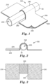
- FIGs. 1 and 2 illustrate a medical article securement device 100 according to one embodiment of the present disclosure.
- FIG. 1 illustrates a securement device 100 coupled to an exemplary medical article 50.
- the medical article 50 is illustrated as being a length of tubing.
- FIG. 2 shows a front elevational view of the securement device 100 and coupled medical article 50 of FIG. 1 .
- the securement device 100 comprises a polymer film 200, the polymer film 200 having a first major surface 210 (e.g ., an upper surface) configured to face away from a patient's skin, and a second major surface 220 ( e.g ., a lower surface) opposite the first major surface 210 that comprises a skin-contact adhesive 230.
- first major surface 210 e.g ., an upper surface
- second major surface 220 e.g ., a lower surface
- the securement device 100 may include a bend 240 defining a channel 250 dimensioned to receive at least a portion of the medical article 50, and a notch 260 formed through the polymer film 200 adjacent the bend 240, such that the notch 260 is aligned with the channel 250.
- the securement device 100 includes at least one flat portion 270 of the polymer film 200 adjacent the bend 240 and the notch 260.
- the bend 240 defining the channel 250 and the notch 260 are located between two flat portions 270 of the polymer film 200.
- the notch 260 is illustrated as being a rectangular portion excised from the polymer film 200, but it could be of other suitable configurations such as, for example square, triangular, circular, or elliptical.
- the securement device 100 may include more than one bend 240 defining a channel 250 dimensioned to receive at least a portion of a medical article 50.
- the securement device 100 may include more than one notch 260, where the notches 260 may be aligned with a corresponding channel 250 or may be located in a position that is not aligned with a channel 250.
- portions of the second major surface 220 of the polymer film 200 may be partially or fully coated with one or more skin-contact adhesives 230 and one or more contact adhesives 235.
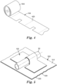
- the medical article securement device 100 may be fabricated such that it may form a roll 500 for storage and comprise perforations 400 that allow for individual securement devices 100 to be separated from the roll 500 for use.
- the bend 240 defining a channel 250 may form as the securement device 100 is affixed to the medical article 50. In some embodiments, the bend 240 defining a channel 250 may be formed before the securement device 100 is affixed to the medical article 50. In some embodiments, the bend 240 and channel 250 are dimensioned to accommodate a particular medical article 50 or portion of a medical article 50 ( see FIGs. 1 and 5 ).
- the securement device 100 may comprise a base layer 300 having a first major surface 310 and a second major surface 320 opposite the first major surface 310.
- the polymer film 200 e.g. , the second major surface 220 of the polymer film 200
- the polymer film 200 can be coupled to the base layer 300 using a variety of coupling means including, but not limited to, one or more of adhesives, cohesives, magnets, welding ( e.g ., sonic [ e.g ., ultrasonic] welding), any thermal bonding or heat sealing technique (e.g ., heat and/or pressure applied to one or both of the components to be coupled), other suitable coupling means, or combinations thereof.
- contact adhesive 235 on at least a portion of the second major surface 220 of the polymer film 200 is adhered to the first major surface 310 of the base layer.
- the base layer 300 first major surface 310 is configured to face away from the patient's skin while the base layer 300 second major surface 320 is configured to face toward the patient's skin and adhere thereto.
- the base layer 300 second major surface 320 may comprise a skin-contact adhesive 330 for adhering to the skin.
- the base layer 300 comprises a laminated structure comprising one or more of a fabric, a woven fibrous web, a nonwoven fibrous web, a knit, a polymeric film, or combinations thereof.
- the base layer may comprise a commercially available dressing configured to adhere to human skin, such as, for example, TEGADERM Flat Film Dressing, available from 3M Company, St. Paul, Minnesota, USA.
- the base layer 300 and the skin-contact adhesive 330 can be perforated to provide openings from the first major surface 310 of the base layer 300 all the way through the second major surface 320 and the skin-contact adhesive 330, which can enhance permeability of the base layer 300 and can minimize moisture build-up at the skin surface underlying the base layer 300.
- the securement device 100 may further include one or more release liners (not shown) that can provide a release layer or surface to the skin-contact adhesive 230, 330 or to the contact adhesive 235 prior to use of the securement device 100.
- release liners suitable for use with systems of the present disclosure can include, but are not limited to, kraft papers, polyethylene, polypropylene, polyester, or combinations thereof.
- Such liners can be coated with release agents, such as fluorochemicals, silicones, or other suitable low surface energy materials.
- Other adhesives and release liner combinations known to those of ordinary skill in the art can be employed in the systems of the present disclosure.
- FIGS. 1 and 5 illustrate methods of coupling various medical articles to medical article securement devices 100 of FIGS. 1-5 . Different coupling methods can be used for different systems, and the methods illustrated in FIGS. 1 and 5 are included merely for illustration purposes.
- a portion thereof is positioned in a channel 250 defined by a bend 240 and a portion passes through a notch 260 formed through the polymer film 200 adjacent the bend 240, thus inhibiting movement of the medical article 50 in at least a direction that is generally normal to the first major surface 210 of the polymer film 200, i.e., to inhibit the medical article 50 from being pulled away from a patient's skin, as well as movement of the medical article 50 in other directions ( e.g ., lateral, oblique).
- PVC tubing was secured to an ABS plastic plate using the securement device Example materials.
- the ABS plate was mounted in a 90° Peel Test Apparatus in an INSTRON load frame (Instron Industrial Products, Norwood, MA, USA), and the end of the tubing was secured in the top grip of the load frame.
- the sample was tested to determine the failure mode at a displacement rate of 20 in/min (50.8 cm/min). Unless otherwise specified, two replicates were performed, and the average peak load is reported.
- Example films were cut into strips 6.2 mm wide and about 4 cm long. The thickness of each film was measured. The films were mounted in the tensile grips of a Q800 DMA (TA Instruments, New Castle, DE, USA) with an initial grip separation between 17 mm and 19 mm. The samples were then tested at an oscillation of 0.2% strain and 1 Hz throughout a temperature ramp from at least -20 °C to 150 °C at a rate of 2 °C per minute. The temperature at which the tan delta signal reached a maximum was recorded as the glass transition temperature.
- Q800 DMA TA Instruments, New Castle, DE, USA
- Pellets of DiARY MM3520 were extruded with a single screw extruder into films 20 cm wide and 0.6 mm thick or 0.3 mm thick.
- An ester-based aliphatic polyurethane film was prepared by reactive extrusion.
- the film was formed from a mixture of FOMREZ 44-111 (45.2 wt%), 1,4-butanediol (10.4 wt%), glycerol (0.3%), BICAT 8 (0.1%), and DESMODUR-W (43.9 wt%) and was 0.13 mm thick.
- An ester-based aliphatic polyurethane film was prepared with the same method as Preparatory Example 2, except the film was 0.05 mm thick.
- An ether-based aliphatic polyurethane was prepared by reactive compounding of a mixture of Terathane 650 (46.0 wt%), 1,4-butanediol (8.8 wt%), and CAPA 3031 (0.4%), bismuth neodecanoate (0.3%), and DESMODUR-W (44.5 wt%) and was 0.13 mm thick.
- the reactive mixtures were mixed for at least five minutes at 170 °C to allow polymerization to occur. Films were then pressed with a hydraulic press at 160 °C to give a thicknesses of 0.3 mm.
- thermosetting ester-based aliphatic polyurethane was prepared by mixing a polyester diol (K-188, 61 wt%), a multifunctional HDI-based isocyanate (DESMODUR N3300, 39 wt%), and dibutyltin dilaurate (0.1 wt%). This mixture was then coated between polyester liners to a thickness of 0.6 mm and allowed to fully cure in an oven at 70 °C.
- a series often polyurethanes were prepared by reactive compounding of a mixture of FOMREZ 44-111, 1,4-butanediol, and MONDUR MLQ in the ratios shown in Table 4.
- the reactive mixtures were mixed for at least five minutes at 195 °C to allow polymerization to occur. Films were then pressed with a hydraulic press at 160 °C to give the thicknesses shown in Table 4.
- a series of three viscoelastic crosslinked polyurethane films were prepared by reactive extrusion.
- the films were formed from a mixture of FOMREZ 44-111, 1,4-butanediol, and MONDUR MLQ in the ratios shown in Table 4.
- the film thicknesses are shown in Table 4.
- a sheet of viscoelastic polyurethane was prepared by pressing pellets of DiARY MM3520 in a Model 2699 hydraulic press (Carver, Inc., Wabash, IN, USA) at 323 °F (162 °C) with force of 20,000 lbf (89,000 N) for 30 minutes using 1 mm thick wooden shims.
- the sheet was then placed on an embossing tool comprising a steel plate with an array of machined posts. Each post was 0.6 mm tall with a square base 0.2 mm x 0.2 mm and a square tip 0.1 mm x 0.1 mm, and they were positioned in an array having square packing and a pitch of 0.3 mm.
- the viscoelastic urethane sheet and the embossing tool were placed in the hydraulic press at a temperature of 323 °F (162 °C) with force of 20,000 lbf (89,000 N) for 5.5 minutes. After cooling, the viscoelastic urethane sheet was removed from the embossing tool to provide an embossed sheet with cavities on one surface matching the dimensions on the posts on the tool. The thickness of the sheet was 1 mm.
- This embossed sheet was folded around a stainless steel tube with a diameter of 5 mm with the embossed pattern toward the outside of the fold, and the assembly was heated in an oven at 130 °C for 20 minutes to form a fold in the embossed sheet with the same radius as the tube.
- each of the two ends of this assembly was folded back approximately 90 degrees and taped to a glass jar (6 cm diameter).
- a glass jar (6 cm diameter).
- the two outside portions of the sheet followed the contour of the glass jar, and the center of the sheet was folded around the stainless steel tube.
- This assembly was heated in a 130 °C oven. After cooling, acrylic adhesive tape was laminated to the surface of the sheet that was not embossed. The resulting laminate was found to conform well to a flexible tube.
- Example 1 0.3 mm Formed Film with Notched Edge
- a piece of 0.3 mm thick film from Preparatory Example 1 was cut to a 5 cm x 6 cm dimension.
- the center section of the sheet parallel to the 5 cm edge was masked with a piece of polyester tape.
- the sheet was then folded generally 180° around a cylindrical wooden applicator stick with a diameter of 2 mm with the polyester tape backing contacting the wood.
- the fold was secured with binder clips, and the remaining flaps of the polymer sheet were taped down to a steel plate with polyester tape.
- This form was heat-set in a 125°C oven for 30 minutes. After cooling, the sheet retained a form with a center loop of polymer protruding approximately 0.7 cm above the surface of the rest of the polymer sheet.
- the polyester tape was removed.
- a 1.2 cm x 1.2 cm section of the formed sheet was removed from the center of one of the 6 cm edges to create a "notch.”
- Acrylic adhesive tape was laminated to the inner face of the formed sheet, and the laminate was used to secure PVC tubing to an ABS plate to form a notched construction, as shown in FIG. 1 .
- the assembly was tested with the Adhesive Test Method with the tubing being pulled from notched edge of the film.
- Example 2 0.3 mm Formed Film
- Example 2 A construction equivalent to that in Example 1 was prepared except the 1.2 cm x 1.2 cm section of the laminate was not removed. The laminate was used to secure PVC tubing to an ABS plate and the assembly was tested with the Adhesive Test Method.
- Example 3 0.6 mm Formed Film
- Example 2 A construction equivalent to that in Example 2 was prepared and tested except that the extruded film was a 0.6 mm thick film from Preparatory Example 1.
- a piece of film from Preparatory Example 2 was cut to 5 cm x 6 cm.
- a 1.2 cm x 1.2 cm section of the laminate was removed from the center of one of the 6 cm edges.
- Acrylic adhesive tape was laminated to one face of the sheet, and the laminate was used to secure PVC tubing to an ABS plate to form a construction similar to that shown in FIG. 1 by wrapping the laminate around the tubing as it was adhered to the ABS plate.
- the assembly was tested with the Adhesive Test Method with the tubing being pulled from notched edge of the film.
- Example 4 A construction equivalent to that in Example 4 was prepared and tested except the 1.2 cm x 1.2 cm section of the laminate was not removed.
- a piece of 0.3 mm thick film from Preparatory Example 1 was cut to 5 cm x 3.5 cm.
- the center section of the sheet parallel to the 5 cm edge was masked with a piece of polyester tape.
- the sheet was then folded generally 180° around a wooden applicator stick with a diameter of 2 mm with the tape contacting the wood.
- the fold was secured with binder clips, and the remaining flaps of the polymer sheet were taped down to a steel plate with polyester tape. This form was heat-set in a 125°C oven for 30 minutes.
- the polyester tape was removed.
- a 1.2 cm x 1.2 cm section of the formed sheet was removed from the center of one of the 3.5 cm edges.
- a piece of 467MP Transfer Tape was laminated to the inner face of the formed sheet.
- a TEGADERM Dressing (6 cm x 7 cm) was applied to an ABS plate, and the surface of the TEGADERM Dressing was wiped with Tape Primer 94. The formed film was then used to secure PVC tubing to the top of the TEGADERM Dressing to form a construction as shown in FIG. 5 . The assembly was tested with the Adhesive Test Method with the tubing being pulled from notched edge of the film.
- a piece of film from Preparatory Example 2 was cut to 5 cm by 3.5 cm.
- a 1.2 cm x 1.2 cm section of the laminate was removed from the center of one of the 3.5 cm edges.
- a piece of 467MP Transfer Tape was laminated to one face of the film.
- a TEGADERM Dressing (6 cm x 7 cm) was applied to an ABS plate, and the surface of the TEGADERM Dressing was wiped with Tape Primer 94.
- the viscoelastic laminate was then used to secure PVC tubing to the top of the TEGADERM Dressing to form a construction as shown in FIG. 5 by wrapping the laminate around the tubing as it was adhered to the TEGADERM dressing.
- the assembly was tested with the Adhesive Test Method with the tubing being pulled from notched edge of the film.
- Example 8 Silicone Adhesive on 0.3 mm Film with Notch
- a piece of 0.3 mm thick film from Preparatory Example 1 was coated with Silicone Adhesive solution (as received) under a knife coater with a 0.1 mm gap. The coating was dried in 70 °C oven for 10 minutes. A piece of this coated film was cut to 5 cm x 3.5 cm. A 1.2 cm x 1.2 cm section of the laminate was removed from the center of one of the 3.5 cm edges. A TEGADERM Dressing (6 cm x 7 cm) was applied to an ABS plate. The coated film was then used to secure PVC tubing to the top of the TEGADERM Dressing to form a construction as shown in FIG. 5 . The assembly was tested with the Adhesive Test Method with the tubing being pulled from notched edge of the film.
- a piece of 0.3 mm thick film from Preparatory Example 1 was compressed in a hydraulic press to produce a film 0.13 mm thick.
- a piece of this thinner film was cut to 5 cm by 6 cm.
- a 1.2 cm x 1.2 cm section of the laminate was removed from the center of one of the 6 cm edges.
- Acrylic adhesive tape was laminated to one face of the sheet, and the laminate was used to secure PVC tubing to an ABS plate to form a construction similar that shown in FIG. 1 by wrapping the laminate around the tubing as it was adhered to the ABS plate.
- the assembly was tested with the Adhesive Test Method with the tubing being pulled from notched edge of the film.
- a piece of 0.3 mm thick film from Preparatory Example 4 was cut to 5 cm x 6 cm.
- a 1.2 cm x 1.2 cm section of the laminate was removed from the center of one of the 6 cm edges.
- Acrylic adhesive tape was laminated to one face of the sheet, and the laminate was used to secure PVC tubing to an ABS plate to form a construction similar to that shown in FIG. 1 by wrapping the laminate around the tubing as it was adhered to the ABS plate.
- the assembly was tested with the Adhesive Test Method with the tubing being pulled from notched edge of the film.
- a piece of 0.6 mm thick film from Preparatory Example 5 was cut to 5 cm x 6 cm.
- a 1.2 cm x 1.2 cm section of the laminate was removed from the center of one of the 6 cm edges.
- Acrylic adhesive tape was laminated to one face of the sheet, and the laminate was used to secure PVC tubing to an ABS plate to form a construction similar to FIG. 1 by wrapping the laminate around the tubing as it was adhered to the ABS plate.
- the assembly was tested with the Adhesive Test Method with the tubing being pulled from notched edge of the film.
- a film of GENIOMER 200 was compression molded to a thickness of 0.3 mm in a hydraulic press at 170 °C. This film was then formed and tested as in Example 1.
- Example 2 A construction equivalent to that in Example 1 was prepared and tested except the film was a 0.3 mm thick sample of ST-3655.
- Example 4 A construction equivalent to that in Example 4 was prepared and tested except the film was a 0.05 mm thick PET film.
- a TEGADERM flat film dressing was first cut into a strip 5 cm wide; additionally a 1.2 cm x 1.2cm square notch was cut from one long edge of the dressing. This modified dressing was then used to secure PVC tubing to an ABS plate with the notch placed over the tubing, such that only a 3.8 cm length of the tubing was covered by the film. The ends of the dressing were then trimmed to leave a 5 cm by 5 cm area, which was again, centered around the tubing. The assembly was tested with the Adhesive Test Method.
- a TEGADERM flat film dressing was first cut into a strip 5 cm wide, which was then used to secure PVC tubing to an ABS plate. The ends of the dressing were then trimmed to leave a 5 cm by 5 cm area of material, with the tubing centered underneath. The assembly was tested with the Adhesive Test Method and gave a peak load of 16.5 N.
- a piece of 0.3 mm thick film from Preparatory Example 1 was compressed in a hydraulic press to produce a film 0.05 mm thick.
- a piece of this thinner film was cut to 5 cm x 6 cm.
- a 1.2 cm x 1.2 cm section of the laminate was removed from the center of one of the 6 cm edges.
- Acrylic adhesive tape was laminated to one face of the sheet, and the laminate was used to secure PVC tubing to an ABS plate to form a construction similar to that shown in FIG. 1 by wrapping the laminate around the tubing as it was adhered to the ABS plate.
- the assembly was tested with the Adhesive Test Method with the tubing being pulled from notched edge of the film.
- a piece of 0.05 mm thick film from Preparatory Example 3 was cut to 5 cm x 6 cm.
- a 1.2 cm x 1.2 cm section of the laminate was removed from the center of one of the 6 cm edges.
- Acrylic adhesive tape was laminated to one face of the sheet, and the laminate was used to secure PVC tubing to an ABS plate to form a construction similar to that shown in FIG. 1 by wrapping the laminate around the tubing as it was adhered to the ABS plate.
- the assembly was tested with the Adhesive Test Method with the tubing being pulled from notched edge of the film.
- Pieces of film from Preparatory Examples 4 through Preparatory Example 16 were each cut to 3 cm x 6 cm.
- the center section of the sheets parallel to the 3 cm edge were masked with polyester tape.
- the sheets were then folded generally 180° around cylindrical wooden applicator sticks with a diameter of 2 mm with the tape contacting the wood.
- the folds were secured with binder clips, and the remaining flaps of the polymer sheets were taped down to a steel plate with polyester tape. This form was heat-set in a 125°C oven for 30 minutes. After cooling, the sheets retained a form with a center loop of polymer protruding above the surface of the rest of the polymer sheet.
- the polyester tape was removed.
- adhesive performance reaches a maximum when the polymer film has a Tg within an optimal range, i.e., about 15 °C to about 45 °C. If the polymer film is too stiff, i.e., Tg is greater than about 45 °C, the polymer film will not conform to the skin, resulting in a low adhesive strength. On the other hand, if the polymer film is too soft, i.e., Tg is less than about 15 °, the polymer film may readily shear off of the skin when a force is applied.
- Tg the viscoelastic properties of a polymer film can be tuned into a specific range to create a medical securement device with desirable adhesive characteristics.
- Examples 1, 4, 10 and 11 and Comparative Examples 1, 2, 3, and 4 all have similar shapes and areas. These Examples were tested with the DMA Test Method and the Adhesive Test Method, and the results are shown in Table 2. Table 2. Constructions with Varied Materials Properties - All Notched Example Material Thickness (mm) DMA Test Method Adhesive Test Method Tg (° C) tan delta max. E' at 30 °C, 1 Hz (MPa) Peak Load (N) Failure Mode EX. 1 Prep. Ex. 1 0.3 42.0 0.70 1641 36.0 Adhesive failure EX. 4 Prep. Ex. 2 0.13 43.9 1.33 235 28.9 Adhesive failure EX. 10 Prep. Ex.
- Adhesive Failure EX. 11 Prep. Ex. 5 0.6 29.0 1.69 22.3 35.9 Adhesive Failure Comp. Ex. 1 GENIOMER 200 0.3 53.3 0.10 5.6 4.0 Adhesive failure Comp. Ex. 2 ST-3655 0.3 -14.2 0.29 32 12.0 Adhesive failure Comp. Ex. 3 PET Film 0.05 111.7 0.15 5125 28.0 Film tear to release tubing Comp. Ex. 4 TEGADERM Film 0.02 - - - 8.9 Film tear to release tubing
- the data in Table 2 show the performance of constructions using polymer films that have the claimed viscoelastic properties (i.e ., Examples 1, 4, 10 and 11) as compared to polymer films that do not have the claimed viscoelastic properties ( i.e ., Comparative Examples 1-4).
- polymer films prepared according to the present disclosure i. e. , Examples 1, 4, 10 and 11
- demonstrate better adhesive performance than the comparative examples i.e ., Comparative Examples 1-4).
- Examples 1, 2, 3, 6, 8, 9, and 10 and Comparative Example 1 were all derived from the material of Preparatory Example 1. These Examples were tested with the Adhesive Test Method, and the results are shown in Table 3. Table 3. Comparison of Construction with Prep. Example 1 Example Material Thickness (mm) Notch Adhesive Test Method Peak Load (N) Failure Mode EX. 1 Prep. Ex. 1 0.3 Yes 36.0 Adhesive failure EX. 2 Prep. Ex. 1 0.3 No 17.3 Adhesive failure EX. 3 Prep. Ex, 1 0.6 No 25.8 Adhesive failure EX. 6 Prep. Ex. 1 and TEGADERM Film 0.3 Yes 35.6 Adhesive failure EX. 8 Prep. Ex.
- Table 3 show the effects of varied device constructions while using the same general materials.
- the presence of a notch in the sample generally improves performance, and thicker polymer films ( i.e ., greater than or equal to 0.3 mm) tend to improve performance.
- Examples 4 and 5 and Comparative Example 7 were all derived from the same polymer formulation (Preparatory Examples 2 and 3). These Examples were tested with the Adhesive Test Method, and the results are shown in Table 4. Table 4. Comparison of Construction with Prep. Examples 2 and 3 Example Material Thickness (mm) Notch Adhesive Test Method Peak Load (N) Failure Mode EX. 4 Prep. Ex. 2 0.13 Yes 28.9 Adhesive failure EX. 5 Prep. Ex. 2 0.13 No 16.0 Adhesive failure EX. 7 Prep. Ex. 2 + TEGADERM 1624W 0.13 Yes 31.1 Film tear to release tubing Comp. Ex. 7 Prep. Ex. 3 0.05 Yes 9.8 Film tear to release tubing
- Examples 12-16 and Comparative Examples 8-15 all have similar dimensions, but are derived from polymers with systematically varied viscoelastic properties. These Examples were tested with the DMA Test Method and the Adhesive Test Method, and the results are shown in Table 5. Table 5. Performance Variation with Viscoelastic Properties Ex. Material FOMREZ 44-111 1,4-BD MLQ Thickness (mm) DMA Test Method Adhesive Test Method Tg (°C) tan delta max. E' at 30 °C, 1 Hz (MPa) Peak Load (N) Comp. Ex. 8 Prep. Ex. 6 29.0% 16.7% 54.3% 0.6 59.0 1.18 1834 0.0 Comp. Ex. 9 Prep. Ex.
- Table 5 show the effects of a single type of construction and single set of raw materials, where the ratios of the materials are systematically varied to span the entire range of viscoelastic properties of interest. Comparative Examples 8-13 are too stiff for optimal performance. Examples 12-16 are in the desired range. Comparative Examples 14 and 15 are too compliant for optimal performance.
Landscapes
- Health & Medical Sciences (AREA)
- Engineering & Computer Science (AREA)
- Life Sciences & Earth Sciences (AREA)
- Animal Behavior & Ethology (AREA)
- Public Health (AREA)
- Heart & Thoracic Surgery (AREA)
- Biomedical Technology (AREA)
- Veterinary Medicine (AREA)
- General Health & Medical Sciences (AREA)
- Textile Engineering (AREA)
- Pulmonology (AREA)
- Biophysics (AREA)
- Anesthesiology (AREA)
- Hematology (AREA)
- Epidemiology (AREA)
- Vascular Medicine (AREA)
- Materials For Medical Uses (AREA)
- Media Introduction/Drainage Providing Device (AREA)
Claims (15)
- Dispositif de fixation (100), comprenant :
un film polymère viscoélastique ayant une première surface principale (210) et une seconde surface principale (220) opposée à la première surface principale (210), le film polymère comprenant :une épaisseur d'au moins 0,1 mm,une température de transition vitreuse, Tg, d'au moins 15 °C et pas supérieure à 45 °C,une tan δ max d'au moins 0,4, etun module de stockage en traction E' d'au moins 10 MPa à 30 °C, 1 Hz lorsqu'il est testé selon l'analyse mécanique dynamique ; etun adhésif (230) sur la seconde surface principale (220) du film polymère. - Dispositif de fixation selon la revendication 1, dans lequel le film polymère comprend un polymère choisi dans le groupe constitué d'un polyuréthane, d'un chlorure de polyvinyle, d'un acrylique, d'un polyester, d'un polyamide, et de combinaisons de ceux-ci.
- Dispositif de fixation selon la revendication 2, dans lequel le polyuréthane est choisi dans le groupe constitué d'un polyuréthane aliphatique à base d'ester, d'un polyuréthane aliphatique à base d'éther, d'un polyuréthane aromatique à base d'ester, d'un polyuréthane aromatique à base d'éther, d'un polyuréthane à base de polycarbonate, et des combinaisons de ceux-ci.
- Dispositif de fixation selon la revendication 1, dans lequel le film polymère est conçu pour comprendre un canal (250) dimensionné pour recevoir au moins une partie d'une tubulure médicale.
- Dispositif de fixation selon la revendication 4, dans lequel le canal (250) est situé adjacent au moins à une partie plate (270) du film polymère.
- Dispositif de fixation selon la revendication 4, dans lequel le canal (250) est situé entre deux parties plates (270) du film polymère.
- Dispositif de fixation selon la revendication 4, comprenant en outre une encoche (260) dans le film polymère positionnée de sorte que l'encoche (260) est alignée avec le canal (250).
- Dispositif de fixation selon la revendication 7, dans lequel l'encoche (260) est dimensionnée pour recevoir au moins une partie d'une tubulure médicale de sorte que la tubulure peut passer de la seconde surface principale du support à travers la première surface principale du support.
- Dispositif de fixation selon la revendication 1, dans lequel la première surface principale (210) du film polymère comporte une modification de surface.
- Dispositif de fixation selon la revendication 1, comprenant en outre une couche de base (300) ayant une première surface principale (310) et une seconde surface principale (320) opposée à la première surface principale (310), dans lequel l'adhésif (230) sur la seconde surface principale (220) du film polymère est fixé par adhérence à une première surface principale (310) de la couche de base (300), et dans lequel la seconde surface principale (320) de la couche de base (300) comprend un adhésif de contact avec la peau.
- Dispositif de fixation de tubulure médicale comprenant :
le film polymère viscoélastique selon la revendication 1, comprenant :un coude formé (240), le coude (240) définissant un canal (250) dimensionné pour recevoir au moins une partie d'une tubulure médicale, etune encoche (260) formée à travers le film polymère adjacent au coude, de sorte que l'encoche (260) est alignée avec le canal. - Dispositif de fixation de tubulure médicale selon la revendication 11, comprenant en outre au moins une partie plate (270) du film polymère adjacente au coude (240) et à l'encoche (260).
- Dispositif de fixation de tubulure médicale selon la revendication 12, dans lequel le coude (240) et l'encoche (260) sont situés entre deux parties plates (270) du film polymère.
- Dispositif de fixation de tubulure médicale selon la revendication 11, dans lequel la première surface principale (210) du film polymère comporte une modification de surface.
- Dispositif de fixation de tubulure médicale selon la revendication 11, comprenant en outre une couche de base (300), dans lequel l'adhésif (230) est fixé par adhérence à la couche de base (300), et dans lequel la couche de base (300) comporte un adhésif de contact avec la peau.
Applications Claiming Priority (2)
| Application Number | Priority Date | Filing Date | Title |
|---|---|---|---|
| US201762508497P | 2017-05-19 | 2017-05-19 | |
| PCT/IB2018/053386 WO2018211416A1 (fr) | 2017-05-19 | 2018-05-15 | Dispositif de fixation d'article médical comprenant un polymère viscoélastique |
Publications (3)
| Publication Number | Publication Date |
|---|---|
| EP3624742A1 EP3624742A1 (fr) | 2020-03-25 |
| EP3624742A4 EP3624742A4 (fr) | 2021-03-31 |
| EP3624742B1 true EP3624742B1 (fr) | 2024-01-03 |
Family
ID=64274092
Family Applications (1)
| Application Number | Title | Priority Date | Filing Date |
|---|---|---|---|
| EP18801835.2A Active EP3624742B1 (fr) | 2017-05-19 | 2018-05-15 | Dispositif de fixation d'article médical comprenant un polymère viscoélastique |
Country Status (5)
| Country | Link |
|---|---|
| US (2) | US11020567B2 (fr) |
| EP (1) | EP3624742B1 (fr) |
| JP (1) | JP6751825B2 (fr) |
| CN (1) | CN110636820A (fr) |
| WO (1) | WO2018211416A1 (fr) |
Families Citing this family (7)
| Publication number | Priority date | Publication date | Assignee | Title |
|---|---|---|---|---|
| EP3816064B1 (fr) * | 2018-07-24 | 2022-12-14 | Kyocera Corporation | Élément portatif et article de type portatif |
| CA3139738A1 (fr) * | 2019-07-12 | 2021-01-21 | Mark ZIELKE | Piston de pointe souple viscoelastique |
| USD947374S1 (en) * | 2021-09-30 | 2022-03-29 | Erin Jessica Lindsay | Clip for urinary drainage tubing connector |
| CN114904124B (zh) * | 2022-04-13 | 2024-05-28 | 首都医科大学宣武医院 | 一种防压疮管路固定装置及固定方法 |
| US20240066186A1 (en) * | 2022-08-26 | 2024-02-29 | Zeus Company Inc. | Uhmwpe dip-coated tubes |
| WO2024049726A2 (fr) * | 2022-08-29 | 2024-03-07 | Becton, Dickinson And Company | Système d'accès vasculaire non intégré à stabilisation |
| USD1068065S1 (en) * | 2023-06-06 | 2025-03-25 | Darrin Hanson | Flex anchoring device for an indwelling urinary catheter |
Family Cites Families (29)
| Publication number | Priority date | Publication date | Assignee | Title |
|---|---|---|---|---|
| USRE24906E (en) | 1955-11-18 | 1960-12-13 | Pressure-sensitive adhesive sheet material | |
| US4112213A (en) | 1964-09-28 | 1978-09-05 | Johnson & Johnson | Pressure sensitive adhesive tapes and method of making same |
| US3389827A (en) | 1967-04-10 | 1968-06-25 | Minnesota Mining & Mfg | Easy-open container and sealing tape |
| US4323557A (en) | 1979-07-31 | 1982-04-06 | Minnesota Mining & Manufacturing Company | Pressure-sensitive adhesive containing iodine |
| US4310509A (en) | 1979-07-31 | 1982-01-12 | Minnesota Mining And Manufacturing Company | Pressure-sensitive adhesive having a broad spectrum antimicrobial therein |
| US4737410A (en) | 1986-11-28 | 1988-04-12 | Minnesota Mining And Manufacturing Company | Polyalkyloxazoline-reinforced acrylic pressure-sensitive adhesive composition |
| GB8706116D0 (en) | 1987-03-14 | 1987-04-15 | Smith & Nephew Ass | Adhesive dressings |
| US5135786A (en) | 1988-10-14 | 1992-08-04 | Mitsubishi Jukogyo Kabushiki Kaisha | Shape memory Transparent body and method of using the same |
| US5131412A (en) | 1991-08-26 | 1992-07-21 | Ellen Rankin | Pediatric intravenous device |
| GB2353219B (en) * | 1999-08-16 | 2004-02-11 | Johnson & Johnson Medical Ltd | Easy to remove adhesive sheets |
| US8592035B2 (en) * | 2004-12-13 | 2013-11-26 | 3M Innovative Properties Company | Adhesive composition, adhesive tape and adhesion structure |
| US9044359B2 (en) * | 2008-04-29 | 2015-06-02 | The Procter & Gamble Company | Disposable absorbent article with absorbent particulate polymer material distributed for improved isolation of body exudates |
| WO2010068502A1 (fr) * | 2008-11-25 | 2010-06-17 | Spiracur Inc. | Dispositif d’application de pression réduite à des surfaces corporelles |
| US8394067B2 (en) * | 2009-05-21 | 2013-03-12 | C.R. Bard, Inc. | Medical device securement system |
| JP2011105858A (ja) * | 2009-11-18 | 2011-06-02 | Nitto Denko Corp | 粘着シート |
| US20120156456A1 (en) * | 2010-03-14 | 2012-06-21 | Mitsubishi Plastics, Inc. | Transparent double-sided self-adhesive sheet |
| JP5174204B2 (ja) * | 2010-04-13 | 2013-04-03 | 三菱樹脂株式会社 | 透明両面粘着シート |
| WO2012050691A2 (fr) | 2010-09-30 | 2012-04-19 | 3M Innovative Properties Company | Dispositif d'écriture comprenant un système de préhension déformable et procédé de fabrication associé |
| CN102429769B (zh) | 2011-12-07 | 2014-04-09 | 唐二虎 | 伤口保护固定装置 |
| US9950143B2 (en) * | 2012-02-07 | 2018-04-24 | Marie Andrea I. Wilborn | Intravenous splint cover and associated methods |
| US10449122B2 (en) * | 2012-04-17 | 2019-10-22 | Fisher & Paykel Healthcare Limited | Tube securement system |
| WO2013162680A1 (fr) | 2012-04-23 | 2013-10-31 | 3M Innovative Properties Company | Articles de fixation conformes et procédés d'utilisation |
| US9757271B2 (en) | 2012-05-29 | 2017-09-12 | Lih-Bin Shih | Hemostasis wound healing device for dynamic elastic injury site |
| CN104994817B (zh) | 2012-06-26 | 2020-02-18 | 3M创新有限公司 | 具有多种粘合剂的医疗敷料 |
| KR20150097666A (ko) * | 2012-12-21 | 2015-08-26 | 쓰리엠 이노베이티브 프로퍼티즈 컴파니 | 플랩을 포함하는 의료용 드레싱 |
| CN105828757B (zh) * | 2013-12-19 | 2018-08-14 | 3M创新有限公司 | 粘弹性医用制品 |
| EP2910224A1 (fr) * | 2014-02-19 | 2015-08-26 | Swiss VX Venentherapie und Forschung GmbH | Bandage de film adhésif de compression médicale |
| JP6574088B2 (ja) | 2014-12-24 | 2019-09-11 | スリーエム イノベイティブ プロパティズ カンパニー | 3次元形状を有する物品を加熱延伸により被覆することが可能なフィルム及び加飾フィルム |
| CN106674471B (zh) * | 2015-11-11 | 2019-09-03 | 万华化学集团股份有限公司 | 一种热塑性聚氨酯弹性体及其制备方法、用途和制品 |
-
2018
- 2018-05-15 EP EP18801835.2A patent/EP3624742B1/fr active Active
- 2018-05-15 CN CN201880033093.4A patent/CN110636820A/zh active Pending
- 2018-05-15 WO PCT/IB2018/053386 patent/WO2018211416A1/fr not_active Ceased
- 2018-05-15 US US16/613,863 patent/US11020567B2/en active Active
- 2018-05-15 JP JP2019564066A patent/JP6751825B2/ja active Active
-
2021
- 2021-03-31 US US17/218,512 patent/US20210213255A1/en not_active Abandoned
Also Published As
| Publication number | Publication date |
|---|---|
| WO2018211416A1 (fr) | 2018-11-22 |
| EP3624742A4 (fr) | 2021-03-31 |
| US11020567B2 (en) | 2021-06-01 |
| US20210213255A1 (en) | 2021-07-15 |
| CN110636820A (zh) | 2019-12-31 |
| JP2020520714A (ja) | 2020-07-16 |
| US20200406011A1 (en) | 2020-12-31 |
| EP3624742A1 (fr) | 2020-03-25 |
| JP6751825B2 (ja) | 2020-09-09 |
Similar Documents
| Publication | Publication Date | Title |
|---|---|---|
| EP3624742B1 (fr) | Dispositif de fixation d'article médical comprenant un polymère viscoélastique | |
| US5052381A (en) | Adhesive wound dressing and perforated shield | |
| US8093445B2 (en) | Wound dressing and method for manufacturing the same | |
| CN105592830B (zh) | 用于穿戴于身体上的物件的承载系统及其制造方法 | |
| EP0409587A1 (fr) | Pansement sous forme de film à faible friction | |
| US20080097334A1 (en) | Intravenous securement device with adhesively interconnected anchoring component and permeable adhesive strip | |
| EP1323437B1 (fr) | Feuille adhésive pour application cutanée et son procédé de fabrication | |
| CN103561785A (zh) | 用于敷用于皮肤的压敏粘合剂及其制备方法 | |
| CN114829517A (zh) | 粘合剂底漆和包含粘合剂底漆的制品 | |
| US20050031860A1 (en) | Pressure-sensitive adhesive sheet and method for producing the same | |
| AU646400B2 (en) | Adhesive dressings | |
| WO2025075183A1 (fr) | Pansement pour orifice vc | |
| JPS59214449A (ja) | 包被手当材料 | |
| US20220112404A1 (en) | Thermally bondable adhesive tape backing | |
| JP4578601B2 (ja) | 絆創膏 | |
| CN116137810A (zh) | 适形的医用敷料 | |
| EP4482555B1 (fr) | Dispositif de fixation, kit comprenant un dispositif de fixation, et procédé de fixation d'un dispositif de fixation sur la peau d'un utilisateur | |
| US20250144370A1 (en) | Cannula stabilization device | |
| Liu | Medical adhesives and skin adhesion | |
| JP4212988B2 (ja) | 粘着シート及び粘着シートの製造方法 | |
| CN121969342A (zh) | Cv港用敷料 | |
| US20210178056A1 (en) | Medical tubing organizer | |
| WO2026053094A1 (fr) | Pansement médical de fixation comportant un pont support | |
| HK1073124A (en) | Pressure-sensitive adhesive sheet and method for producing the same | |
| KR20190018800A (ko) | 압입 구조체가 포함된 마이크로니들 패치 |
Legal Events
| Date | Code | Title | Description |
|---|---|---|---|
| STAA | Information on the status of an ep patent application or granted ep patent |
Free format text: STATUS: THE INTERNATIONAL PUBLICATION HAS BEEN MADE |
|
| PUAI | Public reference made under article 153(3) epc to a published international application that has entered the european phase |
Free format text: ORIGINAL CODE: 0009012 |
|
| STAA | Information on the status of an ep patent application or granted ep patent |
Free format text: STATUS: REQUEST FOR EXAMINATION WAS MADE |
|
| 17P | Request for examination filed |
Effective date: 20191121 |
|
| AK | Designated contracting states |
Kind code of ref document: A1 Designated state(s): AL AT BE BG CH CY CZ DE DK EE ES FI FR GB GR HR HU IE IS IT LI LT LU LV MC MK MT NL NO PL PT RO RS SE SI SK SM TR |
|
| AX | Request for extension of the european patent |
Extension state: BA ME |
|
| DAV | Request for validation of the european patent (deleted) | ||
| DAX | Request for extension of the european patent (deleted) | ||
| A4 | Supplementary search report drawn up and despatched |
Effective date: 20210225 |
|
| RIC1 | Information provided on ipc code assigned before grant |
Ipc: B32B 27/10 20060101ALI20210219BHEP Ipc: B32B 27/30 20060101ALI20210219BHEP Ipc: B32B 27/08 20060101ALI20210219BHEP Ipc: B32B 7/06 20190101ALI20210219BHEP Ipc: B32B 7/12 20060101ALI20210219BHEP Ipc: B32B 5/02 20060101ALI20210219BHEP Ipc: B32B 27/12 20060101ALI20210219BHEP Ipc: A61F 13/15 20060101ALI20210219BHEP Ipc: B32B 3/08 20060101ALI20210219BHEP Ipc: B32B 3/26 20060101ALI20210219BHEP Ipc: B32B 27/36 20060101ALI20210219BHEP Ipc: A61L 15/16 20060101ALI20210219BHEP Ipc: B32B 27/32 20060101ALI20210219BHEP Ipc: A61M 25/02 20060101ALI20210219BHEP Ipc: A61F 13/02 20060101ALI20210219BHEP Ipc: A61F 13/00 20060101AFI20210219BHEP Ipc: B32B 5/26 20060101ALI20210219BHEP Ipc: B32B 27/40 20060101ALI20210219BHEP Ipc: B32B 27/34 20060101ALI20210219BHEP |
|
| REG | Reference to a national code |
Ref country code: DE Ref legal event code: R079 Free format text: PREVIOUS MAIN CLASS: A61F0013000000 Ipc: B32B0029000000 Ref country code: DE Ref legal event code: R079 Ref document number: 602018063674 Country of ref document: DE Free format text: PREVIOUS MAIN CLASS: A61F0013000000 Ipc: B32B0029000000 |
|
| GRAP | Despatch of communication of intention to grant a patent |
Free format text: ORIGINAL CODE: EPIDOSNIGR1 |
|
| STAA | Information on the status of an ep patent application or granted ep patent |
Free format text: STATUS: GRANT OF PATENT IS INTENDED |
|
| RIC1 | Information provided on ipc code assigned before grant |
Ipc: B32B 29/02 20060101ALI20230717BHEP Ipc: B32B 29/00 20060101AFI20230717BHEP |
|
| INTG | Intention to grant announced |
Effective date: 20230804 |
|
| P01 | Opt-out of the competence of the unified patent court (upc) registered |
Effective date: 20231004 |
|
| GRAS | Grant fee paid |
Free format text: ORIGINAL CODE: EPIDOSNIGR3 |
|
| GRAA | (expected) grant |
Free format text: ORIGINAL CODE: 0009210 |
|
| STAA | Information on the status of an ep patent application or granted ep patent |
Free format text: STATUS: THE PATENT HAS BEEN GRANTED |
|
| AK | Designated contracting states |
Kind code of ref document: B1 Designated state(s): AL AT BE BG CH CY CZ DE DK EE ES FI FR GB GR HR HU IE IS IT LI LT LU LV MC MK MT NL NO PL PT RO RS SE SI SK SM TR |
|
| REG | Reference to a national code |
Ref country code: GB Ref legal event code: FG4D |
|
| REG | Reference to a national code |
Ref country code: CH Ref legal event code: EP |
|
| REG | Reference to a national code |
Ref country code: DE Ref legal event code: R096 Ref document number: 602018063674 Country of ref document: DE |
|
| REG | Reference to a national code |
Ref country code: IE Ref legal event code: FG4D |
|
| RAP2 | Party data changed (patent owner data changed or rights of a patent transferred) |
Owner name: SOLVENTUM INTELLECTUAL PROPERTIES COMPANY |
|
| REG | Reference to a national code |
Ref country code: LT Ref legal event code: MG9D |
|
| PG25 | Lapsed in a contracting state [announced via postgrant information from national office to epo] |
Ref country code: ES Free format text: LAPSE BECAUSE OF FAILURE TO SUBMIT A TRANSLATION OF THE DESCRIPTION OR TO PAY THE FEE WITHIN THE PRESCRIBED TIME-LIMIT Effective date: 20240103 |
|
| PG25 | Lapsed in a contracting state [announced via postgrant information from national office to epo] |
Ref country code: ES Free format text: LAPSE BECAUSE OF FAILURE TO SUBMIT A TRANSLATION OF THE DESCRIPTION OR TO PAY THE FEE WITHIN THE PRESCRIBED TIME-LIMIT Effective date: 20240103 |
|
| REG | Reference to a national code |
Ref country code: NL Ref legal event code: MP Effective date: 20240103 |
|
| REG | Reference to a national code |
Ref country code: AT Ref legal event code: MK05 Ref document number: 1646422 Country of ref document: AT Kind code of ref document: T Effective date: 20240103 |
|
| PG25 | Lapsed in a contracting state [announced via postgrant information from national office to epo] |
Ref country code: NL Free format text: LAPSE BECAUSE OF FAILURE TO SUBMIT A TRANSLATION OF THE DESCRIPTION OR TO PAY THE FEE WITHIN THE PRESCRIBED TIME-LIMIT Effective date: 20240103 |
|
| PG25 | Lapsed in a contracting state [announced via postgrant information from national office to epo] |
Ref country code: NL Free format text: LAPSE BECAUSE OF FAILURE TO SUBMIT A TRANSLATION OF THE DESCRIPTION OR TO PAY THE FEE WITHIN THE PRESCRIBED TIME-LIMIT Effective date: 20240103 |
|
| PG25 | Lapsed in a contracting state [announced via postgrant information from national office to epo] |
Ref country code: IS Free format text: LAPSE BECAUSE OF FAILURE TO SUBMIT A TRANSLATION OF THE DESCRIPTION OR TO PAY THE FEE WITHIN THE PRESCRIBED TIME-LIMIT Effective date: 20240503 |
|
| PG25 | Lapsed in a contracting state [announced via postgrant information from national office to epo] |
Ref country code: LT Free format text: LAPSE BECAUSE OF FAILURE TO SUBMIT A TRANSLATION OF THE DESCRIPTION OR TO PAY THE FEE WITHIN THE PRESCRIBED TIME-LIMIT Effective date: 20240103 |
|
| PG25 | Lapsed in a contracting state [announced via postgrant information from national office to epo] |
Ref country code: GR Free format text: LAPSE BECAUSE OF FAILURE TO SUBMIT A TRANSLATION OF THE DESCRIPTION OR TO PAY THE FEE WITHIN THE PRESCRIBED TIME-LIMIT Effective date: 20240404 |
|
| PG25 | Lapsed in a contracting state [announced via postgrant information from national office to epo] |
Ref country code: HR Free format text: LAPSE BECAUSE OF FAILURE TO SUBMIT A TRANSLATION OF THE DESCRIPTION OR TO PAY THE FEE WITHIN THE PRESCRIBED TIME-LIMIT Effective date: 20240103 Ref country code: RS Free format text: LAPSE BECAUSE OF FAILURE TO SUBMIT A TRANSLATION OF THE DESCRIPTION OR TO PAY THE FEE WITHIN THE PRESCRIBED TIME-LIMIT Effective date: 20240403 |
|
| PG25 | Lapsed in a contracting state [announced via postgrant information from national office to epo] |
Ref country code: CZ Free format text: LAPSE BECAUSE OF FAILURE TO SUBMIT A TRANSLATION OF THE DESCRIPTION OR TO PAY THE FEE WITHIN THE PRESCRIBED TIME-LIMIT Effective date: 20240103 Ref country code: AT Free format text: LAPSE BECAUSE OF FAILURE TO SUBMIT A TRANSLATION OF THE DESCRIPTION OR TO PAY THE FEE WITHIN THE PRESCRIBED TIME-LIMIT Effective date: 20240103 |
|
| PG25 | Lapsed in a contracting state [announced via postgrant information from national office to epo] |
Ref country code: RS Free format text: LAPSE BECAUSE OF FAILURE TO SUBMIT A TRANSLATION OF THE DESCRIPTION OR TO PAY THE FEE WITHIN THE PRESCRIBED TIME-LIMIT Effective date: 20240403 Ref country code: NO Free format text: LAPSE BECAUSE OF FAILURE TO SUBMIT A TRANSLATION OF THE DESCRIPTION OR TO PAY THE FEE WITHIN THE PRESCRIBED TIME-LIMIT Effective date: 20240403 Ref country code: LT Free format text: LAPSE BECAUSE OF FAILURE TO SUBMIT A TRANSLATION OF THE DESCRIPTION OR TO PAY THE FEE WITHIN THE PRESCRIBED TIME-LIMIT Effective date: 20240103 Ref country code: IS Free format text: LAPSE BECAUSE OF FAILURE TO SUBMIT A TRANSLATION OF THE DESCRIPTION OR TO PAY THE FEE WITHIN THE PRESCRIBED TIME-LIMIT Effective date: 20240503 Ref country code: HR Free format text: LAPSE BECAUSE OF FAILURE TO SUBMIT A TRANSLATION OF THE DESCRIPTION OR TO PAY THE FEE WITHIN THE PRESCRIBED TIME-LIMIT Effective date: 20240103 Ref country code: GR Free format text: LAPSE BECAUSE OF FAILURE TO SUBMIT A TRANSLATION OF THE DESCRIPTION OR TO PAY THE FEE WITHIN THE PRESCRIBED TIME-LIMIT Effective date: 20240404 Ref country code: CZ Free format text: LAPSE BECAUSE OF FAILURE TO SUBMIT A TRANSLATION OF THE DESCRIPTION OR TO PAY THE FEE WITHIN THE PRESCRIBED TIME-LIMIT Effective date: 20240103 Ref country code: BG Free format text: LAPSE BECAUSE OF FAILURE TO SUBMIT A TRANSLATION OF THE DESCRIPTION OR TO PAY THE FEE WITHIN THE PRESCRIBED TIME-LIMIT Effective date: 20240103 Ref country code: AT Free format text: LAPSE BECAUSE OF FAILURE TO SUBMIT A TRANSLATION OF THE DESCRIPTION OR TO PAY THE FEE WITHIN THE PRESCRIBED TIME-LIMIT Effective date: 20240103 |
|
| PG25 | Lapsed in a contracting state [announced via postgrant information from national office to epo] |
Ref country code: PL Free format text: LAPSE BECAUSE OF FAILURE TO SUBMIT A TRANSLATION OF THE DESCRIPTION OR TO PAY THE FEE WITHIN THE PRESCRIBED TIME-LIMIT Effective date: 20240103 Ref country code: PT Free format text: LAPSE BECAUSE OF FAILURE TO SUBMIT A TRANSLATION OF THE DESCRIPTION OR TO PAY THE FEE WITHIN THE PRESCRIBED TIME-LIMIT Effective date: 20240503 |
|
| PG25 | Lapsed in a contracting state [announced via postgrant information from national office to epo] |
Ref country code: SE Free format text: LAPSE BECAUSE OF FAILURE TO SUBMIT A TRANSLATION OF THE DESCRIPTION OR TO PAY THE FEE WITHIN THE PRESCRIBED TIME-LIMIT Effective date: 20240103 Ref country code: PT Free format text: LAPSE BECAUSE OF FAILURE TO SUBMIT A TRANSLATION OF THE DESCRIPTION OR TO PAY THE FEE WITHIN THE PRESCRIBED TIME-LIMIT Effective date: 20240503 Ref country code: PL Free format text: LAPSE BECAUSE OF FAILURE TO SUBMIT A TRANSLATION OF THE DESCRIPTION OR TO PAY THE FEE WITHIN THE PRESCRIBED TIME-LIMIT Effective date: 20240103 Ref country code: LV Free format text: LAPSE BECAUSE OF FAILURE TO SUBMIT A TRANSLATION OF THE DESCRIPTION OR TO PAY THE FEE WITHIN THE PRESCRIBED TIME-LIMIT Effective date: 20240103 |
|
| REG | Reference to a national code |
Ref country code: DE Ref legal event code: R097 Ref document number: 602018063674 Country of ref document: DE |
|
| PG25 | Lapsed in a contracting state [announced via postgrant information from national office to epo] |
Ref country code: DK Free format text: LAPSE BECAUSE OF FAILURE TO SUBMIT A TRANSLATION OF THE DESCRIPTION OR TO PAY THE FEE WITHIN THE PRESCRIBED TIME-LIMIT Effective date: 20240103 |
|
| PG25 | Lapsed in a contracting state [announced via postgrant information from national office to epo] |
Ref country code: SM Free format text: LAPSE BECAUSE OF FAILURE TO SUBMIT A TRANSLATION OF THE DESCRIPTION OR TO PAY THE FEE WITHIN THE PRESCRIBED TIME-LIMIT Effective date: 20240103 |
|
| PG25 | Lapsed in a contracting state [announced via postgrant information from national office to epo] |
Ref country code: EE Free format text: LAPSE BECAUSE OF FAILURE TO SUBMIT A TRANSLATION OF THE DESCRIPTION OR TO PAY THE FEE WITHIN THE PRESCRIBED TIME-LIMIT Effective date: 20240103 |
|
| PG25 | Lapsed in a contracting state [announced via postgrant information from national office to epo] |
Ref country code: SK Free format text: LAPSE BECAUSE OF FAILURE TO SUBMIT A TRANSLATION OF THE DESCRIPTION OR TO PAY THE FEE WITHIN THE PRESCRIBED TIME-LIMIT Effective date: 20240103 |
|
| PG25 | Lapsed in a contracting state [announced via postgrant information from national office to epo] |
Ref country code: SM Free format text: LAPSE BECAUSE OF FAILURE TO SUBMIT A TRANSLATION OF THE DESCRIPTION OR TO PAY THE FEE WITHIN THE PRESCRIBED TIME-LIMIT Effective date: 20240103 Ref country code: SK Free format text: LAPSE BECAUSE OF FAILURE TO SUBMIT A TRANSLATION OF THE DESCRIPTION OR TO PAY THE FEE WITHIN THE PRESCRIBED TIME-LIMIT Effective date: 20240103 Ref country code: RO Free format text: LAPSE BECAUSE OF FAILURE TO SUBMIT A TRANSLATION OF THE DESCRIPTION OR TO PAY THE FEE WITHIN THE PRESCRIBED TIME-LIMIT Effective date: 20240103 Ref country code: EE Free format text: LAPSE BECAUSE OF FAILURE TO SUBMIT A TRANSLATION OF THE DESCRIPTION OR TO PAY THE FEE WITHIN THE PRESCRIBED TIME-LIMIT Effective date: 20240103 Ref country code: DK Free format text: LAPSE BECAUSE OF FAILURE TO SUBMIT A TRANSLATION OF THE DESCRIPTION OR TO PAY THE FEE WITHIN THE PRESCRIBED TIME-LIMIT Effective date: 20240103 |
|
| PLBE | No opposition filed within time limit |
Free format text: ORIGINAL CODE: 0009261 |
|
| STAA | Information on the status of an ep patent application or granted ep patent |
Free format text: STATUS: NO OPPOSITION FILED WITHIN TIME LIMIT |
|
| PG25 | Lapsed in a contracting state [announced via postgrant information from national office to epo] |
Ref country code: IT Free format text: LAPSE BECAUSE OF FAILURE TO SUBMIT A TRANSLATION OF THE DESCRIPTION OR TO PAY THE FEE WITHIN THE PRESCRIBED TIME-LIMIT Effective date: 20240103 |
|
| 26N | No opposition filed |
Effective date: 20241007 |
|
| REG | Reference to a national code |
Ref country code: CH Ref legal event code: PL |
|
| PG25 | Lapsed in a contracting state [announced via postgrant information from national office to epo] |
Ref country code: IT Free format text: LAPSE BECAUSE OF FAILURE TO SUBMIT A TRANSLATION OF THE DESCRIPTION OR TO PAY THE FEE WITHIN THE PRESCRIBED TIME-LIMIT Effective date: 20240103 |
|
| PG25 | Lapsed in a contracting state [announced via postgrant information from national office to epo] |
Ref country code: MC Free format text: LAPSE BECAUSE OF FAILURE TO SUBMIT A TRANSLATION OF THE DESCRIPTION OR TO PAY THE FEE WITHIN THE PRESCRIBED TIME-LIMIT Effective date: 20240103 |
|
| PG25 | Lapsed in a contracting state [announced via postgrant information from national office to epo] |
Ref country code: LU Free format text: LAPSE BECAUSE OF NON-PAYMENT OF DUE FEES Effective date: 20240515 |
|
| GBPC | Gb: european patent ceased through non-payment of renewal fee |
Effective date: 20240515 |
|
| PG25 | Lapsed in a contracting state [announced via postgrant information from national office to epo] |
Ref country code: MC Free format text: LAPSE BECAUSE OF FAILURE TO SUBMIT A TRANSLATION OF THE DESCRIPTION OR TO PAY THE FEE WITHIN THE PRESCRIBED TIME-LIMIT Effective date: 20240103 Ref country code: LU Free format text: LAPSE BECAUSE OF NON-PAYMENT OF DUE FEES Effective date: 20240515 Ref country code: CH Free format text: LAPSE BECAUSE OF NON-PAYMENT OF DUE FEES Effective date: 20240531 |
|
| REG | Reference to a national code |
Ref country code: BE Ref legal event code: MM Effective date: 20240531 |
|
| PG25 | Lapsed in a contracting state [announced via postgrant information from national office to epo] |
Ref country code: IE Free format text: LAPSE BECAUSE OF NON-PAYMENT OF DUE FEES Effective date: 20240515 |
|
| PG25 | Lapsed in a contracting state [announced via postgrant information from national office to epo] |
Ref country code: SI Free format text: LAPSE BECAUSE OF FAILURE TO SUBMIT A TRANSLATION OF THE DESCRIPTION OR TO PAY THE FEE WITHIN THE PRESCRIBED TIME-LIMIT Effective date: 20240103 Ref country code: BE Free format text: LAPSE BECAUSE OF NON-PAYMENT OF DUE FEES Effective date: 20240531 |
|
| PG25 | Lapsed in a contracting state [announced via postgrant information from national office to epo] |
Ref country code: FR Free format text: LAPSE BECAUSE OF NON-PAYMENT OF DUE FEES Effective date: 20240531 |
|
| PG25 | Lapsed in a contracting state [announced via postgrant information from national office to epo] |
Ref country code: GB Free format text: LAPSE BECAUSE OF NON-PAYMENT OF DUE FEES Effective date: 20240515 |
|
| PGFP | Annual fee paid to national office [announced via postgrant information from national office to epo] |
Ref country code: DE Payment date: 20250423 Year of fee payment: 8 |
|
| PG25 | Lapsed in a contracting state [announced via postgrant information from national office to epo] |
Ref country code: CY Free format text: LAPSE BECAUSE OF FAILURE TO SUBMIT A TRANSLATION OF THE DESCRIPTION OR TO PAY THE FEE WITHIN THE PRESCRIBED TIME-LIMIT; INVALID AB INITIO Effective date: 20180515 |
|
| PG25 | Lapsed in a contracting state [announced via postgrant information from national office to epo] |
Ref country code: HU Free format text: LAPSE BECAUSE OF FAILURE TO SUBMIT A TRANSLATION OF THE DESCRIPTION OR TO PAY THE FEE WITHIN THE PRESCRIBED TIME-LIMIT; INVALID AB INITIO Effective date: 20180515 |
|
| PG25 | Lapsed in a contracting state [announced via postgrant information from national office to epo] |
Ref country code: FI Free format text: LAPSE BECAUSE OF FAILURE TO SUBMIT A TRANSLATION OF THE DESCRIPTION OR TO PAY THE FEE WITHIN THE PRESCRIBED TIME-LIMIT Effective date: 20240103 |