EP3625504B1 - Schéma d'étagement de carburant binaire permettant d'améliorer les émissions de débit dans la combustion d'une turbine à gaz à pré-mélange pauvre - Google Patents
Schéma d'étagement de carburant binaire permettant d'améliorer les émissions de débit dans la combustion d'une turbine à gaz à pré-mélange pauvre Download PDFInfo
- Publication number
- EP3625504B1 EP3625504B1 EP17727039.4A EP17727039A EP3625504B1 EP 3625504 B1 EP3625504 B1 EP 3625504B1 EP 17727039 A EP17727039 A EP 17727039A EP 3625504 B1 EP3625504 B1 EP 3625504B1
- Authority
- EP
- European Patent Office
- Prior art keywords
- premixers
- fuel
- staging
- burners
- step size
- Prior art date
- Legal status (The legal status is an assumption and is not a legal conclusion. Google has not performed a legal analysis and makes no representation as to the accuracy of the status listed.)
- Active
Links
Images









Classifications
-
- F—MECHANICAL ENGINEERING; LIGHTING; HEATING; WEAPONS; BLASTING
- F23—COMBUSTION APPARATUS; COMBUSTION PROCESSES
- F23N—REGULATING OR CONTROLLING COMBUSTION
- F23N1/00—Regulating fuel supply
-
- F—MECHANICAL ENGINEERING; LIGHTING; HEATING; WEAPONS; BLASTING
- F23—COMBUSTION APPARATUS; COMBUSTION PROCESSES
- F23R—GENERATING COMBUSTION PRODUCTS OF HIGH PRESSURE OR HIGH VELOCITY, e.g. GAS-TURBINE COMBUSTION CHAMBERS
- F23R3/00—Continuous combustion chambers using liquid or gaseous fuel
- F23R3/28—Continuous combustion chambers using liquid or gaseous fuel characterised by the fuel supply
- F23R3/34—Feeding into different combustion zones
- F23R3/346—Feeding into different combustion zones for staged combustion
-
- F—MECHANICAL ENGINEERING; LIGHTING; HEATING; WEAPONS; BLASTING
- F02—COMBUSTION ENGINES; HOT-GAS OR COMBUSTION-PRODUCT ENGINE PLANTS
- F02C—GAS-TURBINE PLANTS; AIR INTAKES FOR JET-PROPULSION PLANTS; CONTROLLING FUEL SUPPLY IN AIR-BREATHING JET-PROPULSION PLANTS
- F02C7/00—Features, components parts, details or accessories, not provided for in, or of interest apart form groups F02C1/00 - F02C6/00; Air intakes for jet-propulsion plants
- F02C7/22—Fuel supply systems
- F02C7/228—Dividing fuel between various burners
-
- F—MECHANICAL ENGINEERING; LIGHTING; HEATING; WEAPONS; BLASTING
- F02—COMBUSTION ENGINES; HOT-GAS OR COMBUSTION-PRODUCT ENGINE PLANTS
- F02C—GAS-TURBINE PLANTS; AIR INTAKES FOR JET-PROPULSION PLANTS; CONTROLLING FUEL SUPPLY IN AIR-BREATHING JET-PROPULSION PLANTS
- F02C7/00—Features, components parts, details or accessories, not provided for in, or of interest apart form groups F02C1/00 - F02C6/00; Air intakes for jet-propulsion plants
- F02C7/22—Fuel supply systems
- F02C7/232—Fuel valves; Draining valves or systems
-
- F—MECHANICAL ENGINEERING; LIGHTING; HEATING; WEAPONS; BLASTING
- F02—COMBUSTION ENGINES; HOT-GAS OR COMBUSTION-PRODUCT ENGINE PLANTS
- F02C—GAS-TURBINE PLANTS; AIR INTAKES FOR JET-PROPULSION PLANTS; CONTROLLING FUEL SUPPLY IN AIR-BREATHING JET-PROPULSION PLANTS
- F02C9/00—Controlling gas-turbine plants; Controlling fuel supply in air- breathing jet-propulsion plants
- F02C9/26—Control of fuel supply
- F02C9/263—Control of fuel supply by means of fuel metering valves
-
- F—MECHANICAL ENGINEERING; LIGHTING; HEATING; WEAPONS; BLASTING
- F02—COMBUSTION ENGINES; HOT-GAS OR COMBUSTION-PRODUCT ENGINE PLANTS
- F02C—GAS-TURBINE PLANTS; AIR INTAKES FOR JET-PROPULSION PLANTS; CONTROLLING FUEL SUPPLY IN AIR-BREATHING JET-PROPULSION PLANTS
- F02C9/00—Controlling gas-turbine plants; Controlling fuel supply in air- breathing jet-propulsion plants
- F02C9/26—Control of fuel supply
- F02C9/28—Regulating systems responsive to plant or ambient parameters, e.g. temperature, pressure, rotor speed
-
- F—MECHANICAL ENGINEERING; LIGHTING; HEATING; WEAPONS; BLASTING
- F23—COMBUSTION APPARATUS; COMBUSTION PROCESSES
- F23R—GENERATING COMBUSTION PRODUCTS OF HIGH PRESSURE OR HIGH VELOCITY, e.g. GAS-TURBINE COMBUSTION CHAMBERS
- F23R3/00—Continuous combustion chambers using liquid or gaseous fuel
- F23R3/28—Continuous combustion chambers using liquid or gaseous fuel characterised by the fuel supply
- F23R3/286—Continuous combustion chambers using liquid or gaseous fuel characterised by the fuel supply having fuel-air premixing devices
-
- F—MECHANICAL ENGINEERING; LIGHTING; HEATING; WEAPONS; BLASTING
- F23—COMBUSTION APPARATUS; COMBUSTION PROCESSES
- F23N—REGULATING OR CONTROLLING COMBUSTION
- F23N2237/00—Controlling
- F23N2237/02—Controlling two or more burners
-
- F—MECHANICAL ENGINEERING; LIGHTING; HEATING; WEAPONS; BLASTING
- F23—COMBUSTION APPARATUS; COMBUSTION PROCESSES
- F23N—REGULATING OR CONTROLLING COMBUSTION
- F23N2241/00—Applications
- F23N2241/20—Gas turbines
Definitions
- the invention relates to a method for staging premixers in a combustion system, and more particularly, to a method wherein fuel circuits are activated or deactivated in stages to deliver fuel or stop fuel delivery, respectively, to the premixers wherein a staging step size between consecutive stages is in accordance with a power of base two staging scheme.
- a fluid is used to produce rotational motion.
- a gas turbine 10 is schematically shown.
- the turbine 10 includes a compressor section 12, which draws in ambient air 14 and delivers compressed air 16 to a combustion section 18.
- a fuel supply 20 delivers fuel 22 to the combustion section 18 where it is combined with the compressed air 16 and the fuel 22 is burned to produce high temperature combustion gas 24.
- the combustion gas 24 is expanded through a turbine section 26, which includes a series of rows of stationary vanes and rotor blades.
- the combustion gas 24 causes the rotor blades to rotate to produce shaft horsepower for driving the compressor 12 and a load, such as an electrical generator 28.
- Expanded gas 30 is either exhausted to the atmosphere directly, or in a combined cycle plant, may be exhausted to atmosphere through a heat recovery steam generator.
- Exhaust gas produced by the gas turbine may include certain emissions, such as nitrogen oxides (NOx), carbon monoxide (CO), and unburned hydrocarbons (UHCs). It is desirable to eliminate or substantially reduce the amount of such emissions in the exhaust gas prior to releasing the exhaust gas into the atmosphere.
- a method for reducing emissions includes the use of a Dry Low Emissions (DLE) combustion system in the gas turbine.
- DLE Dry Low Emissions
- a known premixed combustion process is used wherein compressed air 16 and fuel 22 are premixed in premixer elements (premixers) prior to combustion to provide an appropriate mixture of air and fuel that reduces emissions by controlling combustor flame temperature.
- the gas turbine is provided with multiple burners each provided with multiple premixers capable of providing premixed air and fuel and being activated and deactivated in stages.
- a method for staging fuel circuits in a combustion system for a gas turbine having a compressor section and a turbine section includes providing a plurality of burners each including premixers wherein compressed air from the compressor section is provided to the premixers.
- the method also includes providing a plurality of fuel circuits that deliver fuel to the premixers to provide premixed air and fuel used for combustion in the combustion system.
- the method includes associating premixers with each fuel circuit in accordance with a power of base two pattern.
- the method includes activating or deactivating the premixers in stages by activating or deactivating an associated fuel circuit to deliver fuel or stop fuel delivery, respectively, to the premixers wherein a staging step size between consecutive stages is in accordance with a power of base two staging scheme.
- a binary staging scheme is utilized in order to stage, or sequence, the activation or deactivation of selected premixers or burners in order to maintain combustor flame temperature within a desired range suitable for reducing gas turbine emissions.
- Fig. 2 shows a fuel circuit/Block Scheduling Valve (BSV) arrangement 40 for a binary staging configuration for staging premixers in a gas turbine.
- Fuel from a fuel supply 42 is delivered to a group or subset of associated premixers or burners (i.e. combustors) 44 via associated fuel circuits 46.
- Each fuel circuit 46 includes a single fuel valve 48 such as a known Block Scheduling Valve (BSV) 48 that controls fuel delivery to the associated premixers or burners 44.
- BSV Block Scheduling Valve
- each BSV 48 either opens to deliver fuel to associated premixers or burners 44 (i.e. activate the fuel circuit 46 and the premixers or burners 44) or closes to stop fuel delivery to the associated premixers or burners 44 (i.e. deactivate the fuel circuit and the premixers or burners 44).
- Fuel delivery from the fuel supply 42 to the fuel control valves 48 is controlled by a known fuel metering valve (FMV) 50.
- FMV fuel metering valve
- the BSVs 48 and fuel metering valve 50 are controlled by a controller.
- a power of base two pattern is used to determine the number of premixers or burners 44 associated with each fuel circuit 46 or BSV 48.
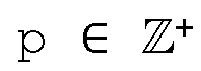
- BSV1, BSV2, BSV3 and BSV4 are associated with p, 2p, 4p and 8p premixers or burners 44, respectively, as shown in Fig. 2 .
- p 2 for example, then BSV1, BSV2, BSV3 and BSV4 are associated with 2, 4, 8 and 16 premixers or burners 44, respectively.
- BSV2, BSV3 and BSV4 are each able to turn activate or deactivate more than one premixer or burner 44.
- staging steps 15p, 14p, 13p, 12p, 11p, 10p, 9p, 8p, 7p, 6p, 5p, 4p, 3p, 2p, 1p) result in 14 valve manoeuvres.
- the invention minimizes the number of BSVs 48 that are required for a given number of staging steps, thus reducing system cost and complexity.
- up to 14 valves, such as 14 BSVs 48, would be necessary to achieve the same number of staging steps of resolution p.
- Fig. 3 depicts an implementation of a binary staging scheme 52 for premixers or burners 44 wherein selected premixers or burners 44 (see Fig. 2 ) are activated or deactivated during a sequence of staging steps 54A-54FV.
- combustor inlet temperature is a function of turbine power and ambient temperature.
- fuel circuits 46 are re-combined (i.e. activated or deactivated) such that a staging step size p between consecutive steps 54A-54FV is minimized as combustor inlet temperature changes in order to minimize any substantial jumps/increases in combustor flame temperature.
- the fuel circuits 46 are grouped in powers of base two, the fuel circuits 46 are re-combined such that the staging step size is always equal to p.
- the number of active premixers or burners 44 (“NA” in Fig. 3 ) is equal to the total number of premixers or burners 44 ("N” in Fig. 3 ).
- premixers or burners 44 are deactivated in accordance with the binary staging scheme 52, thus decreasing the number of active premixers or burners 44.
- the number of active premixers or burners 44 decreases by the staging step size p (step 54B) and subsequently by increasing consecutive multiples of p (N-p, N-2p, N-3p, N-4p, N-5p, N-6p, N-7p etc. at steps 54C, 54D, 54E, 54F, 54G, 54H, respectively) wherein additional premixers or burners 44 are deactivated.
- This pattern continues until the number of active premixers or burners 44 is equivalent to the staging step size p (step 54FV - "first/final value").
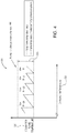
- Fig. 4 is a graph 56 depicting an exemplary burner or combustor flame temperature 58 for a gas turbine relative to combustor inlet temperature 60.
- premixers or burners 44 are activated in accordance with the binary staging scheme 52, thus increasing the number of active premixers or burners 44.
- the number of active premixers or burners 44 increases by decreasing multiples of p (N-3p, N-2p, N-p at steps 54D, 54C, 54B, respectively) as combustor inlet temperature 60 increases. This pattern continues until the number of active premixers or burners 44 is equivalent to the total number of premixers or burners 44.
- the combustor flame temperature 58 for the gas turbine remains within a target flame temperature range 59 during each staging step thereby minimizing pollutant emissions at all combustor inlet temperatures.
- FIG. 5 a schematic cross sectional view of an exemplary combustion section 62 of a gas turbine 64 is shown.
- the combustion section 62 includes burners 66 that are arranged in a can or annular architecture, for example. Each burner 66 includes at least one premixer.
- the gas turbine 64 includes 4 fuel circuits (Fuel Circuit 1, Fuel Circuit 2, Fuel Circuit 3, Fuel Circuit 4) and p is selected as 2. Fuel Circuit 1 is associated with 2 burners (p), Fuel Circuit 2 is associated with 4 burners (2p), Fuel Circuit 3 is associated with 8 burners (4p) and Fuel Circuit 4 is associated with 16 burners (8p). Further, the total number of burners is 30 in accordance with Eqn. 2.
- Fuel Circuits 1-4 each deliver fuel to all of the premixers associated with a burner 66.
- Fuel Circuits 1-4 each include a single BSV 48 for controlling fuel delivery to all of the premixers associated with a burner 66.
- opening or closing a BSV 48 activates or deactivates all of the premixers associated with a burner 66 and turns the burner 66 on or off, respectively.
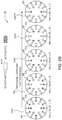
- a binary staging scheme 52 for staging the burners 66 described in relation to Fig. 5 is shown.
- the number of active burners 66 decreases by the staging step size p (step 54B) and subsequently by increasing consecutive multiples of p (N-p, N-2p, N-3p, N-4p, N-5p, N-6p, N-7p, N-8p, N-9p, N-10p, N-11p, N-12p, N-13p) at steps 54B, 54C, 54D, 54E, 54F, 54G, 54H, 541, 54J, 54K, 54L, 54M, 54N, respectively) wherein additional burners 66 are deactivated as previously described in relation to Fig. 3 .
- NA N - p).
- Additional burners 66 are deactivated in accordance with the binary staging scheme 52 described in relation to Fig.
- step 54FV the number of active burners is 20, 18, 16, 14, 12, 10, 8, 6, 4 at steps 54F, 54G, 54H, 541, 54J, 54K, 54L, 54M, 54N, respectively, until the number of active burners 66 is equivalent to the staging step size 2 (i.e. p; step 54FV).
- FIG. 7 a schematic cross sectional view of an alternate embodiment of a combustion section 68 of the gas turbine 64 is shown.
- the combustion section 68 includes a plurality of burners 70 wherein each burner 70 includes at least one premixer 72.
- the premixers 72 within each burner 70 are staged in accordance with the binary staging scheme 52.
- the gas turbine 64 includes four fuel circuits (Fuel Circuits 1-4) and p is selected as 10. Fuel Circuit 1 is associated with 10 premixers (p), Fuel Circuit 2 is associated with 20 premixers (2p), Fuel Circuit 3 is associated with 40 premixers (4p) and Fuel Circuit 4 is associated with 80 premixers (8p).
- the total number of premixers is 150 in accordance with Eqn. 2.
- Each burner 70 includes premixers 72 that are associated with each of the fuel circuits (Fuel Circuits 1-4).
- each burner 70 includes 1 premixer 72 associated with Fuel Circuit 1, 2 premixers 72 associated with Fuel Circuit 2, 4 premixers 72 associated with Fuel Circuit 3 and 8 premixers 72 associated with Fuel Circuit 4.
- Fuel Circuits 1-4 each include a single BSV 48 for controlling fuel delivery to associated premixers 72. Thus, opening or closing a BSV 48 activates or deactivates associated premixers 72 in each of the burners 70 to provide staging of premixers 72 within each burner 70.
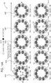
- a binary staging scheme 52 for staging the premixers 72 described in relation to Fig. 7 is shown.
- the number of active premixers 72 decreases by the staging step size p (step 54B) and subsequently by increasing consecutive multiples of p (N-p, N-2p, N-3p, N-4p, N-5p, N-6p, N-7p, N-8p, N-9p, N-10p, N-11p, N-12p, N-13p at steps 54B, 54C, 54D, 54E, 54F, 54G, 54H, 541, 54J, 54K, 54L, 54M, 54N, respectively) wherein additional premixers 72 are deactivated as previously described in relation to Fig. 3 .
- NA N - p
- Additional premixers 72 are deactivated in accordance with the binary staging scheme 52 described in relation to Fig.
- step 54FV the number of active premixers is 100, 90, 80, 70, 60, 50, 40, 30, 20 at steps 54F, 54G, 54H, 541, 54J, 54K, 54L, 54M, 54N, respectively, until the number of active premixers 72 is equivalent to the staging step size 10 (i.e. p; step 54FV).
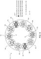
- FIG. 9 a schematic cross sectional view of a further embodiment of a combustion section 74 of the gas turbine 64 is shown.
- Fuel Circuits 1-4 are distributed asymmetrically between the burners.
- the gas turbine 64 includes four fuel circuits (Fuel Circuits 1-4), p is selected as 10 and each of the Fuel Circuits 1-4 include a single BSV 48 for controlling fuel delivery to associated premixers 72 as previously described.
- first 76 and second 78 burners include premixers 72 associated with a single fuel circuit, i.e. Fuel Circuit 4 for example. Additional pairs of burners include premixers 72 associated with more than one fuel circuit.
- third 80 and fourth 82 burners include premixers 72 associated with Fuel Circuits 3 and 4
- fifth 84 and sixth 86 burners include premixers 72 associated with Fuel Circuits 1 and 4
- seventh 88 and eighth 90 burners include premixers 72 associated with Fuel Circuits 2 and 4
- ninth 92 and tenth 94 burners include premixers 72 associated with Fuel Circuits 3 and 4.
- a binary staging scheme 52 for staging the premixers 72 described in relation to Fig. 9 is shown.
- the number of active premixers associated with staging steps 54A-54FV for the configuration shown in Fig. 9 is identical to that described in relation to Figs. 8A and 8B (i.e. 150, 140, 130, 120, 110, 100, 90, 80, 70, 60, 50, 40, 30, 20, 10, respectively).
- different sets of premixers are activated or deactivated than those shown in Figs. 8A and 8B due to the asymmetrical distribution of the Fuel Circuits 1-4 relative to the burners.
- opening or closing the BSV 48 associated with Fuel Circuit 4 activates or deactivates all of the premixers 72 associated with the first 76 and second 78 burners and turns the first 76 and second 78 burners on or off, respectively, at step 541.
- opening or closing the BSV 48 associated with Fuel Circuit 4 activates or deactivates all of the premixers 72 associated with the first 76 and second 78 burners and turns the first 76 and second 78 burners on or off, respectively, at step 541.
- opening or closing the BSV 48 associated with Fuel Circuit 4 activates or deactivates all of the premixers 72 associated with the first 76 and second 78 burners and turns the first 76 and second 78 burners on or off, respectively, at step 541.
- step 541 of Fig. 8A it can be seen that selected premixers 72 are still activated and that the associated burners 70 are still on.
- a combustion section may include a plurality of tiles wherein each tile is associated with a burner.
- each tile is associated with a burner.
- the entire disclosure of a patent application entitled “Gas Turbine Combustion System Having Tiles That Include Premixers", Attorney Docket No. 2017P02079WO, serial number to be determined, is hereby incorporated by reference in its entirety.
- Fig. 11 an exemplary integrated tile 96 is shown.
- the tile 96 includes a plurality of premixers 98 (i.e. a set of premixers) that extend between the front 100 and rear 102 surfaces.
- Each premixer 98 includes an inlet end 112 and outlet end 114 (one outlet end 114 is shown in a partial cutaway view in Fig. 11 for illustrative purposes) located on the front 100 and rear 102 surfaces, respectively, of the tile 96.
- the inlet ends 112 receive compressed air 16 moving on a tile air flow path 116.
- the tile 96 includes at least one gas fuel inlet 118 which receives gaseous fuel that is delivered to a subset of premixers 98 via fuel galleries.
- the gas fuel enters a selected premixer 98 in a direction substantially transverse to the direction of the air entering the premixer 98 through the inlet end 112.
- the premixers 98 have a known configuration and may include known inner and outer swirlers that cause rotation of the air flow received through their respective inlet end 112. Rotation of the incoming air within the premixer 98 due to the swirlers, in conjunction with gas fuel introduced into the premixer 98, premixes the fuel and air prior to combustion so as to provide an appropriate mixture of air and fuel to burner that reduces emissions.
- the air-fuel mixture then exits the premixer 98 via the outlet end 114, passes through a lattice section 120 and ultimately enters an associated burner for combustion.
- the gas turbine includes four fuel circuits (Fuel Circuits 1-4) and p is selected as 24, resulting in 360 total premixers.
- the gas turbine may include 24 tiles 96 each associated with a burner.
- Fuel Circuit 1 is associated with 1 premixer 98
- Fuel Circuit 2 is associated with 2 premixers 98
- Fuel Circuit 3 is associated with 4 premixers 98
- Fuel Circuit 4 is associated with 8 premixers 98.
- Fuel Circuits 1-4 each include a single BSV 48 for controlling fuel delivery to associated premixers 98.
- opening or closing a BSV 48 activates or deactivates associated premixers 98 in the tile 96 to provide staging of premixers 98 in accordance the binary staging scheme 52.
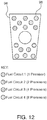
- step 54A staging steps of a binary staging scheme 52 for staging the premixers 98 included in the single tile 96 described in relation to Fig. 12 are shown.
- step 54A the premixers 98 are deactivated in accordance with the binary staging scheme 52, thus decreasing the number of active premixers 98.
- the number of active premixers 98 decreases by the staging step size p (step 54B) and subsequently by increasing consecutive multiples of p (N-p, N-2p, N-3p, N-4p, N-5p, N-6p, N-7p administratN-13p) at steps 54C, 54D, 54E, 54F, 54G, 54H «54N, respectively).
- step 54M all the premixers are inactive and a fuel injector may be activated for turbine start-up. Due to the binary staging scheme 52, each of the combustors for all the tiles 24 in a combustion section are simultaneously and identically staged.
- the binary staging scheme minimizes the number of valves needed to control the premixers or burners. Further, the binary staging scheme minimizes the size of the staging steps, thus minimizing fluctuations in combustor flame temperature.
- Use of a power of base two pattern is preferred over powers of other bases.
- use of a base three staging scheme results in relatively large staging steps because of the grouping sizes: p, 3p, 9p, 27p, 81p, etc., therefore resulting in undesirable large fluctuations in combustor flame temperature.
- the invention addresses disadvantages associated with conventional staging schemes that utilize relatively few valves and thus provide relatively limited control over the flame temperature and result in poor turndown.
- other conventional staging schemes that utilize many valves may provide precise control over the flame temperature but are relatively expensive and complicated to implement.
- a non-binary staging scheme could result in as many valves as staging steps, whereas the binary staging scheme has fewer valves n than the number of staging steps S, as per Eqn. (3).
- the invention enables improvement in the turndown capability of the gas turbine to maintain combustor flame temperatures in a limited range. This is achieved without the use of a bleed system, thus avoiding a thermal efficiency penalty for the gas turbine.
Landscapes
- Engineering & Computer Science (AREA)
- Chemical & Material Sciences (AREA)
- Combustion & Propulsion (AREA)
- Mechanical Engineering (AREA)
- General Engineering & Computer Science (AREA)
Claims (9)
- Procédé d'étagement de prémélangeurs dans un système de combustion pour une turbine à gaz (64) ayant une section compresseur et une section turbine, comprenant :la fourniture d'une pluralité de brûleurs (44, 66, 70, 76, 78, 80, 82, 84, 86, 88, 90, 92, 94) incluant chacun des prémélangeurs (72, 98) ;la fourniture d'air comprimé provenant de la section compresseur aux prémélangeurs (72, 98) ;la fourniture d'une pluralité de circuits de carburant (46) qui distribuent du carburant aux prémélangeurs (72, 98) pour fournir de l'air et du carburant prémélangés utilisés pour la combustion dans le système de combustion ;l'association de prémélangeurs (72, 98) à chaque circuit de carburant (46) conformément à une puissance de profil base deux ; etl'activation ou la désactivation des prémélangeurs (72, 98) par étages par activation ou désactivation d'un circuit de carburant associé (46) pour distribuer du carburant ou arrêter la distribution de carburant, respectivement, aux prémélangeurs (72, 98), une taille d'étape d'étagement entre des étages consécutifs étant conforme à une puissance de schéma d'étagement base deux,caractérisé ence que le nombre de prémélangeurs (72, 98) ou de brûleurs (44, 66, 70, 76, 78, 80, 82, 84, 86, 88, 90, 92, 94) actifs diminue en augmentant les multiples consécutifs de la taille d'étape d'étagement à mesure que la température d'entrée de la chambre de combustion diminue, des circuits de carburant associés (46) étant recombinés conformément à une puissance de profil base deux, ouen ce que le nombre de prémélangeurs (72, 98) ou de brûleurs (44, 66, 70, 76, 78, 80, 82, 84, 86, 88, 90, 92, 94) actifs augmente en diminuant des multiples consécutifs de la taille d'étape d'étagement à mesure que la température d'entrée de la chambre de combustion augmente, des circuits de carburant associés (46) étant recombinés conformément à une puissance de profil base deux.
- Procédé selon la revendication 1, dans lequel le nombre de prémélangeurs (72, 98) associés à un circuit de carburant donné (46) n est donné par :

- Procédé selon la revendication 1, dans lequel le nombre total de prémélangeurs (72, 98) pour un nombre donné de circuits de carburant (46) est donné par :


- Procédé selon la revendication 3, dans lequel le nombre total d'étapes d'étagement possibles est donné par :

- Procédé selon la revendication 1, dans lequel la taille d'étape d'étagement suit un profil incluant N-p, N-2p, N-3p, N-4p, N-5p, N-6p, N-7p dans lequel N = nombre total de prémélangeurs (72, 98) et p est la taille d'étape d'étagement et le profil continuant jusqu'à ce que le nombre de prémélangeurs (72, 98) ou de brûleurs (44, 66, 70, 76, 78, 80, 82, 84, 86, 88, 90, 92, 94) actifs soit équivalent à la taille d'étape d'étagement p à mesure que la température d'entrée de chambre de combustion est diminuée.
- Procédé selon la revendication 1, dans lequel le schéma d'étagement maintient une température de flamme de brûleur dans une plage appropriée pour réduire les émissions de turbine à gaz.
- Procédé selon la revendication 1, dans lequel l'activation ou la désactivation d'un circuit de carburant (46) est commandée par une valve à carburant (48).
- Procédé selon la revendication 1, dans lequel au moins un brûleur (44, 66, 70, 76, 78, 80, 82, 84, 86, 88, 90, 92, 94) inclut des premiers prémélangeurs (72, 98) qui sont associés à un premier circuit de carburant (46), et dans lequel l'activation ou la désactivation du premier circuit de carburant (46) active ou désactive les premiers prémélangeurs (72, 98) et allume ou éteint le brûleur (44, 66, 70, 76, 78, 80, 82, 84, 86, 88, 90, 92, 94), respectivement.
- Procédé selon l'une quelconque des revendications précédentes 1 à 8, comprenant la fourniture d'une tuile (96) associée à chaque brûleur (44, 66, 70, 76, 78, 80, 82, 84, 86, 88, 90, 92, 94), chaque tuile (96) incluant une pluralité de prémélangeurs (72, 98).
Applications Claiming Priority (1)
| Application Number | Priority Date | Filing Date | Title |
|---|---|---|---|
| PCT/US2017/032797 WO2018212761A1 (fr) | 2017-05-16 | 2017-05-16 | Schéma d'étagement de carburant binaire permettant d'améliorer les émissions de débit dans la combustion d'une turbine à gaz à pré-mélange pauvre |
Publications (2)
| Publication Number | Publication Date |
|---|---|
| EP3625504A1 EP3625504A1 (fr) | 2020-03-25 |
| EP3625504B1 true EP3625504B1 (fr) | 2021-11-24 |
Family
ID=58873881
Family Applications (1)
| Application Number | Title | Priority Date | Filing Date |
|---|---|---|---|
| EP17727039.4A Active EP3625504B1 (fr) | 2017-05-16 | 2017-05-16 | Schéma d'étagement de carburant binaire permettant d'améliorer les émissions de débit dans la combustion d'une turbine à gaz à pré-mélange pauvre |
Country Status (5)
| Country | Link |
|---|---|
| US (1) | US11125437B2 (fr) |
| EP (1) | EP3625504B1 (fr) |
| CN (1) | CN110612419B (fr) |
| ES (1) | ES2901604T3 (fr) |
| WO (1) | WO2018212761A1 (fr) |
Families Citing this family (1)
| Publication number | Priority date | Publication date | Assignee | Title |
|---|---|---|---|---|
| US12215866B2 (en) | 2022-02-18 | 2025-02-04 | General Electric Company | Combustor for a turbine engine having a fuel-air mixer including a set of mixing passages |
Family Cites Families (24)
| Publication number | Priority date | Publication date | Assignee | Title |
|---|---|---|---|---|
| US5351477A (en) | 1993-12-21 | 1994-10-04 | General Electric Company | Dual fuel mixer for gas turbine combustor |
| JP3183053B2 (ja) * | 1994-07-20 | 2001-07-03 | 株式会社日立製作所 | ガスタービン燃焼器及びガスタービン |
| JPH09318044A (ja) | 1996-05-31 | 1997-12-12 | Mitsubishi Electric Corp | 液体燃料燃焼装置 |
| US6082111A (en) | 1998-06-11 | 2000-07-04 | Siemens Westinghouse Power Corporation | Annular premix section for dry low-NOx combustors |
| GB9929601D0 (en) | 1999-12-16 | 2000-02-09 | Rolls Royce Plc | A combustion chamber |
| GB0111788D0 (en) | 2001-05-15 | 2001-07-04 | Rolls Royce Plc | A combustion chamber |
| US6715295B2 (en) | 2002-05-22 | 2004-04-06 | Siemens Westinghouse Power Corporation | Gas turbine pilot burner water injection and method of operation |
| US6962055B2 (en) | 2002-09-27 | 2005-11-08 | United Technologies Corporation | Multi-point staging strategy for low emission and stable combustion |
| JP3975232B2 (ja) * | 2002-10-22 | 2007-09-12 | 川崎重工業株式会社 | ガスタービンエンジンの制御方法および制御システム |
| US6968699B2 (en) * | 2003-05-08 | 2005-11-29 | General Electric Company | Sector staging combustor |
| EP1531305A1 (fr) | 2003-11-12 | 2005-05-18 | United Technologies Corporation | Injecteur de carburant multi-point |
| JP4015656B2 (ja) * | 2004-11-17 | 2007-11-28 | 三菱重工業株式会社 | ガスタービン燃焼器 |
| WO2007033306A2 (fr) | 2005-09-13 | 2007-03-22 | Rolls-Royce Corporation, Ltd. | Systemes de combustion pour turbine a gaz |
| WO2007119115A2 (fr) | 2005-12-14 | 2007-10-25 | Rolls-Royce Power Engineering Plc | Injecteurs de prémélange de turbine à gaz |
| US7950215B2 (en) * | 2007-11-20 | 2011-05-31 | Siemens Energy, Inc. | Sequential combustion firing system for a fuel system of a gas turbine engine |
| GB201100602D0 (en) | 2011-01-14 | 2011-03-02 | Rolls Royce Plc | Gas turbine engine |
| US9719685B2 (en) * | 2011-12-20 | 2017-08-01 | General Electric Company | System and method for flame stabilization |
| JP5458121B2 (ja) * | 2012-01-27 | 2014-04-02 | 株式会社日立製作所 | ガスタービン燃焼器およびガスタービン燃焼器の運転方法 |
| US9291098B2 (en) * | 2012-11-14 | 2016-03-22 | General Electric Company | Turbomachine and staged combustion system of a turbomachine |
| US9243567B2 (en) * | 2012-11-27 | 2016-01-26 | General Electric Company | System and method to control a gas turbine subject to fuel composition variation |
| DE102013003444A1 (de) | 2013-02-26 | 2014-09-11 | Rolls-Royce Deutschland Ltd & Co Kg | Prall-effusionsgekühlte Schindel einer Gasturbinenbrennkammer mit verlängerten Effusionsbohrungen |
| US20150128600A1 (en) | 2013-11-13 | 2015-05-14 | Krishna C. Miduturi | Fuel injection system for a turbine engine |
| US20160201918A1 (en) | 2014-09-18 | 2016-07-14 | Rolls-Royce Canada, Ltd. | Small arrayed swirler system for reduced emissions and noise |
| JP6945468B2 (ja) * | 2018-02-06 | 2021-10-06 | 三菱パワー株式会社 | ガスタービン燃焼器、ガスタービン及びガスタービン燃焼器の制御方法 |
-
2017
- 2017-05-16 EP EP17727039.4A patent/EP3625504B1/fr active Active
- 2017-05-16 CN CN201780090891.6A patent/CN110612419B/zh active Active
- 2017-05-16 WO PCT/US2017/032797 patent/WO2018212761A1/fr not_active Ceased
- 2017-05-16 US US16/499,611 patent/US11125437B2/en active Active
- 2017-05-16 ES ES17727039T patent/ES2901604T3/es active Active
Also Published As
| Publication number | Publication date |
|---|---|
| CN110612419B (zh) | 2022-01-25 |
| ES2901604T3 (es) | 2022-03-23 |
| CN110612419A (zh) | 2019-12-24 |
| US11125437B2 (en) | 2021-09-21 |
| EP3625504A1 (fr) | 2020-03-25 |
| WO2018212761A1 (fr) | 2018-11-22 |
| US20200103115A1 (en) | 2020-04-02 |
Similar Documents
| Publication | Publication Date | Title |
|---|---|---|
| US6684642B2 (en) | Gas turbine engine having a multi-stage multi-plane combustion system | |
| US6772583B2 (en) | Can combustor for a gas turbine engine | |
| EP1426689B1 (fr) | Chambre de combustion de turbine à gaz comprenant des brûleurs à prémélange ayant des géométries différentes | |
| EP1843097B1 (fr) | Conditionneur de débit d'air pour chambre de combustion de turbine à gaz | |
| EP1795802B1 (fr) | Contrôle indépendant du carburant pilote dans une buse secondaire d'injection | |
| US9708983B2 (en) | Gas turbine with sequential combustion arrangement | |
| US20170058784A1 (en) | System and method for maintaining emissions compliance while operating a gas turbine at turndown condition | |
| US7107773B2 (en) | Turbine engine sequenced combustion | |
| EP2619507B1 (fr) | Chambre de combustion dotée d'un unique brûleur à mélange air/carburant limité et micro-turbine à gaz récupéré | |
| US7784261B2 (en) | Combined cycle power plant | |
| CN102809176A (zh) | 气动力燃料喷嘴 | |
| US20140352312A1 (en) | Injector for introducing a fuel-air mixture into a combustion chamber | |
| US20090139236A1 (en) | Premixing device for enhanced flameholding and flash back resistance | |
| US11041623B2 (en) | Gas turbine combustor with heat exchanger between rich combustion zone and secondary combustion zone | |
| JPH11311416A (ja) | 低エミッションガスタ―ビン燃焼器 | |
| US20170058770A1 (en) | System and method for decoupling steam production dependency from gas turbine load level | |
| EP3625504B1 (fr) | Schéma d'étagement de carburant binaire permettant d'améliorer les émissions de débit dans la combustion d'une turbine à gaz à pré-mélange pauvre | |
| US11493206B2 (en) | Gas turbine combustor having main fuel valves independently adjustable | |
| US20170058771A1 (en) | System and method for generating steam during gas turbine low-load conditions | |
| EP2607649A2 (fr) | Système et procédé permettant de réguler les émissions d'oxygène provenant d'une turbine à gaz | |
| JP6740375B2 (ja) | 排気を減らすための選択的燃焼器制御の方法 | |
| EP3702669B1 (fr) | Procédé de fonctionnement d'une chambre de combustion séquentielle d'une turbine à gaz et turbine à gaz comprenant cette chambre de combustion séquentielle |
Legal Events
| Date | Code | Title | Description |
|---|---|---|---|
| STAA | Information on the status of an ep patent application or granted ep patent |
Free format text: STATUS: UNKNOWN |
|
| STAA | Information on the status of an ep patent application or granted ep patent |
Free format text: STATUS: THE INTERNATIONAL PUBLICATION HAS BEEN MADE |
|
| PUAI | Public reference made under article 153(3) epc to a published international application that has entered the european phase |
Free format text: ORIGINAL CODE: 0009012 |
|
| STAA | Information on the status of an ep patent application or granted ep patent |
Free format text: STATUS: REQUEST FOR EXAMINATION WAS MADE |
|
| 17P | Request for examination filed |
Effective date: 20191114 |
|
| AK | Designated contracting states |
Kind code of ref document: A1 Designated state(s): AL AT BE BG CH CY CZ DE DK EE ES FI FR GB GR HR HU IE IS IT LI LT LU LV MC MK MT NL NO PL PT RO RS SE SI SK SM TR |
|
| AX | Request for extension of the european patent |
Extension state: BA ME |
|
| DAV | Request for validation of the european patent (deleted) | ||
| DAX | Request for extension of the european patent (deleted) | ||
| STAA | Information on the status of an ep patent application or granted ep patent |
Free format text: STATUS: EXAMINATION IS IN PROGRESS |
|
| 17Q | First examination report despatched |
Effective date: 20201208 |
|
| RAP1 | Party data changed (applicant data changed or rights of an application transferred) |
Owner name: SIEMENS ENERGY GLOBAL GMBH & CO. KG |
|
| GRAP | Despatch of communication of intention to grant a patent |
Free format text: ORIGINAL CODE: EPIDOSNIGR1 |
|
| STAA | Information on the status of an ep patent application or granted ep patent |
Free format text: STATUS: GRANT OF PATENT IS INTENDED |
|
| INTG | Intention to grant announced |
Effective date: 20210617 |
|
| RIN1 | Information on inventor provided before grant (corrected) |
Inventor name: FURI, MARC Inventor name: ENGELHARDT, MATTHEW Inventor name: SANCHEZ, FABIAN Inventor name: SCARINCI, THOMAS |
|
| GRAS | Grant fee paid |
Free format text: ORIGINAL CODE: EPIDOSNIGR3 |
|
| GRAA | (expected) grant |
Free format text: ORIGINAL CODE: 0009210 |
|
| STAA | Information on the status of an ep patent application or granted ep patent |
Free format text: STATUS: THE PATENT HAS BEEN GRANTED |
|
| AK | Designated contracting states |
Kind code of ref document: B1 Designated state(s): AL AT BE BG CH CY CZ DE DK EE ES FI FR GB GR HR HU IE IS IT LI LT LU LV MC MK MT NL NO PL PT RO RS SE SI SK SM TR |
|
| REG | Reference to a national code |
Ref country code: GB Ref legal event code: FG4D |
|
| REG | Reference to a national code |
Ref country code: AT Ref legal event code: REF Ref document number: 1450138 Country of ref document: AT Kind code of ref document: T Effective date: 20211215 |
|
| REG | Reference to a national code |
Ref country code: DE Ref legal event code: R096 Ref document number: 602017049767 Country of ref document: DE |
|
| REG | Reference to a national code |
Ref country code: IE Ref legal event code: FG4D |
|
| REG | Reference to a national code |
Ref country code: ES Ref legal event code: FG2A Ref document number: 2901604 Country of ref document: ES Kind code of ref document: T3 Effective date: 20220323 |
|
| REG | Reference to a national code |
Ref country code: LT Ref legal event code: MG9D |
|
| REG | Reference to a national code |
Ref country code: NL Ref legal event code: MP Effective date: 20211124 |
|
| REG | Reference to a national code |
Ref country code: AT Ref legal event code: MK05 Ref document number: 1450138 Country of ref document: AT Kind code of ref document: T Effective date: 20211124 |
|
| PG25 | Lapsed in a contracting state [announced via postgrant information from national office to epo] |
Ref country code: RS Free format text: LAPSE BECAUSE OF FAILURE TO SUBMIT A TRANSLATION OF THE DESCRIPTION OR TO PAY THE FEE WITHIN THE PRESCRIBED TIME-LIMIT Effective date: 20211124 Ref country code: LT Free format text: LAPSE BECAUSE OF FAILURE TO SUBMIT A TRANSLATION OF THE DESCRIPTION OR TO PAY THE FEE WITHIN THE PRESCRIBED TIME-LIMIT Effective date: 20211124 Ref country code: FI Free format text: LAPSE BECAUSE OF FAILURE TO SUBMIT A TRANSLATION OF THE DESCRIPTION OR TO PAY THE FEE WITHIN THE PRESCRIBED TIME-LIMIT Effective date: 20211124 Ref country code: BG Free format text: LAPSE BECAUSE OF FAILURE TO SUBMIT A TRANSLATION OF THE DESCRIPTION OR TO PAY THE FEE WITHIN THE PRESCRIBED TIME-LIMIT Effective date: 20220224 Ref country code: AT Free format text: LAPSE BECAUSE OF FAILURE TO SUBMIT A TRANSLATION OF THE DESCRIPTION OR TO PAY THE FEE WITHIN THE PRESCRIBED TIME-LIMIT Effective date: 20211124 |
|
| PG25 | Lapsed in a contracting state [announced via postgrant information from national office to epo] |
Ref country code: IS Free format text: LAPSE BECAUSE OF FAILURE TO SUBMIT A TRANSLATION OF THE DESCRIPTION OR TO PAY THE FEE WITHIN THE PRESCRIBED TIME-LIMIT Effective date: 20220324 Ref country code: SE Free format text: LAPSE BECAUSE OF FAILURE TO SUBMIT A TRANSLATION OF THE DESCRIPTION OR TO PAY THE FEE WITHIN THE PRESCRIBED TIME-LIMIT Effective date: 20211124 Ref country code: PT Free format text: LAPSE BECAUSE OF FAILURE TO SUBMIT A TRANSLATION OF THE DESCRIPTION OR TO PAY THE FEE WITHIN THE PRESCRIBED TIME-LIMIT Effective date: 20220324 Ref country code: PL Free format text: LAPSE BECAUSE OF FAILURE TO SUBMIT A TRANSLATION OF THE DESCRIPTION OR TO PAY THE FEE WITHIN THE PRESCRIBED TIME-LIMIT Effective date: 20211124 Ref country code: NO Free format text: LAPSE BECAUSE OF FAILURE TO SUBMIT A TRANSLATION OF THE DESCRIPTION OR TO PAY THE FEE WITHIN THE PRESCRIBED TIME-LIMIT Effective date: 20220224 Ref country code: NL Free format text: LAPSE BECAUSE OF FAILURE TO SUBMIT A TRANSLATION OF THE DESCRIPTION OR TO PAY THE FEE WITHIN THE PRESCRIBED TIME-LIMIT Effective date: 20211124 Ref country code: LV Free format text: LAPSE BECAUSE OF FAILURE TO SUBMIT A TRANSLATION OF THE DESCRIPTION OR TO PAY THE FEE WITHIN THE PRESCRIBED TIME-LIMIT Effective date: 20211124 Ref country code: HR Free format text: LAPSE BECAUSE OF FAILURE TO SUBMIT A TRANSLATION OF THE DESCRIPTION OR TO PAY THE FEE WITHIN THE PRESCRIBED TIME-LIMIT Effective date: 20211124 Ref country code: GR Free format text: LAPSE BECAUSE OF FAILURE TO SUBMIT A TRANSLATION OF THE DESCRIPTION OR TO PAY THE FEE WITHIN THE PRESCRIBED TIME-LIMIT Effective date: 20220225 |
|
| PG25 | Lapsed in a contracting state [announced via postgrant information from national office to epo] |
Ref country code: SM Free format text: LAPSE BECAUSE OF FAILURE TO SUBMIT A TRANSLATION OF THE DESCRIPTION OR TO PAY THE FEE WITHIN THE PRESCRIBED TIME-LIMIT Effective date: 20211124 Ref country code: SK Free format text: LAPSE BECAUSE OF FAILURE TO SUBMIT A TRANSLATION OF THE DESCRIPTION OR TO PAY THE FEE WITHIN THE PRESCRIBED TIME-LIMIT Effective date: 20211124 Ref country code: RO Free format text: LAPSE BECAUSE OF FAILURE TO SUBMIT A TRANSLATION OF THE DESCRIPTION OR TO PAY THE FEE WITHIN THE PRESCRIBED TIME-LIMIT Effective date: 20211124 Ref country code: EE Free format text: LAPSE BECAUSE OF FAILURE TO SUBMIT A TRANSLATION OF THE DESCRIPTION OR TO PAY THE FEE WITHIN THE PRESCRIBED TIME-LIMIT Effective date: 20211124 Ref country code: DK Free format text: LAPSE BECAUSE OF FAILURE TO SUBMIT A TRANSLATION OF THE DESCRIPTION OR TO PAY THE FEE WITHIN THE PRESCRIBED TIME-LIMIT Effective date: 20211124 Ref country code: CZ Free format text: LAPSE BECAUSE OF FAILURE TO SUBMIT A TRANSLATION OF THE DESCRIPTION OR TO PAY THE FEE WITHIN THE PRESCRIBED TIME-LIMIT Effective date: 20211124 |
|
| REG | Reference to a national code |
Ref country code: DE Ref legal event code: R097 Ref document number: 602017049767 Country of ref document: DE |
|
| PLBE | No opposition filed within time limit |
Free format text: ORIGINAL CODE: 0009261 |
|
| STAA | Information on the status of an ep patent application or granted ep patent |
Free format text: STATUS: NO OPPOSITION FILED WITHIN TIME LIMIT |
|
| PG25 | Lapsed in a contracting state [announced via postgrant information from national office to epo] |
Ref country code: AL Free format text: LAPSE BECAUSE OF FAILURE TO SUBMIT A TRANSLATION OF THE DESCRIPTION OR TO PAY THE FEE WITHIN THE PRESCRIBED TIME-LIMIT Effective date: 20211124 |
|
| 26N | No opposition filed |
Effective date: 20220825 |
|
| PG25 | Lapsed in a contracting state [announced via postgrant information from national office to epo] |
Ref country code: SI Free format text: LAPSE BECAUSE OF FAILURE TO SUBMIT A TRANSLATION OF THE DESCRIPTION OR TO PAY THE FEE WITHIN THE PRESCRIBED TIME-LIMIT Effective date: 20211124 |
|
| REG | Reference to a national code |
Ref country code: CH Ref legal event code: PL |
|
| REG | Reference to a national code |
Ref country code: BE Ref legal event code: MM Effective date: 20220531 |
|
| PG25 | Lapsed in a contracting state [announced via postgrant information from national office to epo] |
Ref country code: MC Free format text: LAPSE BECAUSE OF FAILURE TO SUBMIT A TRANSLATION OF THE DESCRIPTION OR TO PAY THE FEE WITHIN THE PRESCRIBED TIME-LIMIT Effective date: 20211124 Ref country code: LU Free format text: LAPSE BECAUSE OF NON-PAYMENT OF DUE FEES Effective date: 20220516 Ref country code: LI Free format text: LAPSE BECAUSE OF NON-PAYMENT OF DUE FEES Effective date: 20220531 Ref country code: CH Free format text: LAPSE BECAUSE OF NON-PAYMENT OF DUE FEES Effective date: 20220531 |
|
| PG25 | Lapsed in a contracting state [announced via postgrant information from national office to epo] |
Ref country code: IE Free format text: LAPSE BECAUSE OF NON-PAYMENT OF DUE FEES Effective date: 20220516 |
|
| PG25 | Lapsed in a contracting state [announced via postgrant information from national office to epo] |
Ref country code: BE Free format text: LAPSE BECAUSE OF NON-PAYMENT OF DUE FEES Effective date: 20220531 |
|
| PG25 | Lapsed in a contracting state [announced via postgrant information from national office to epo] |
Ref country code: MK Free format text: LAPSE BECAUSE OF FAILURE TO SUBMIT A TRANSLATION OF THE DESCRIPTION OR TO PAY THE FEE WITHIN THE PRESCRIBED TIME-LIMIT Effective date: 20211124 Ref country code: CY Free format text: LAPSE BECAUSE OF FAILURE TO SUBMIT A TRANSLATION OF THE DESCRIPTION OR TO PAY THE FEE WITHIN THE PRESCRIBED TIME-LIMIT Effective date: 20211124 |
|
| PG25 | Lapsed in a contracting state [announced via postgrant information from national office to epo] |
Ref country code: HU Free format text: LAPSE BECAUSE OF FAILURE TO SUBMIT A TRANSLATION OF THE DESCRIPTION OR TO PAY THE FEE WITHIN THE PRESCRIBED TIME-LIMIT; INVALID AB INITIO Effective date: 20170516 |
|
| PG25 | Lapsed in a contracting state [announced via postgrant information from national office to epo] |
Ref country code: MT Free format text: LAPSE BECAUSE OF FAILURE TO SUBMIT A TRANSLATION OF THE DESCRIPTION OR TO PAY THE FEE WITHIN THE PRESCRIBED TIME-LIMIT Effective date: 20211124 |
|
| PGFP | Annual fee paid to national office [announced via postgrant information from national office to epo] |
Ref country code: DE Payment date: 20250528 Year of fee payment: 9 |
|
| PGFP | Annual fee paid to national office [announced via postgrant information from national office to epo] |
Ref country code: ES Payment date: 20250611 Year of fee payment: 9 |
|
| PGFP | Annual fee paid to national office [announced via postgrant information from national office to epo] |
Ref country code: IT Payment date: 20250522 Year of fee payment: 9 |
|
| PGFP | Annual fee paid to national office [announced via postgrant information from national office to epo] |
Ref country code: FR Payment date: 20250526 Year of fee payment: 9 |
|
| PG25 | Lapsed in a contracting state [announced via postgrant information from national office to epo] |
Ref country code: TR Free format text: LAPSE BECAUSE OF FAILURE TO SUBMIT A TRANSLATION OF THE DESCRIPTION OR TO PAY THE FEE WITHIN THE PRESCRIBED TIME-LIMIT Effective date: 20211124 |
|
| PGFP | Annual fee paid to national office [announced via postgrant information from national office to epo] |
Ref country code: GB Payment date: 20260323 Year of fee payment: 10 |