EP3626505A1 - Système et procédé de fourniture d'énergie électrique redondante - Google Patents
Système et procédé de fourniture d'énergie électrique redondante Download PDFInfo
- Publication number
- EP3626505A1 EP3626505A1 EP18195131.0A EP18195131A EP3626505A1 EP 3626505 A1 EP3626505 A1 EP 3626505A1 EP 18195131 A EP18195131 A EP 18195131A EP 3626505 A1 EP3626505 A1 EP 3626505A1
- Authority
- EP
- European Patent Office
- Prior art keywords
- storage units
- vehicle
- power
- power management
- management unit
- Prior art date
- Legal status (The legal status is an assumption and is not a legal conclusion. Google has not performed a legal analysis and makes no representation as to the accuracy of the status listed.)
- Granted
Links
Images
Classifications
-
- H—ELECTRICITY
- H02—GENERATION; CONVERSION OR DISTRIBUTION OF ELECTRIC POWER
- H02J—ELECTRIC POWER NETWORKS; CIRCUIT ARRANGEMENTS OR SYSTEMS FOR SUPPLYING OR DISTRIBUTING ELECTRIC POWER; SYSTEMS FOR STORING ELECTRIC ENERGY
- H02J9/00—Circuit arrangements for emergency or stand-by power supply, e.g. for emergency lighting
- H02J9/04—Circuit arrangements for emergency or stand-by power supply, e.g. for emergency lighting in which the distribution system is disconnected from the normal source and connected to a standby source
- H02J9/06—Circuit arrangements for emergency or stand-by power supply, e.g. for emergency lighting in which the distribution system is disconnected from the normal source and connected to a standby source with automatic change-over, e.g. UPS systems
-
- B—PERFORMING OPERATIONS; TRANSPORTING
- B60—VEHICLES IN GENERAL
- B60L—PROPULSION OF ELECTRICALLY-PROPELLED VEHICLES; SUPPLYING ELECTRIC POWER FOR AUXILIARY EQUIPMENT OF ELECTRICALLY-PROPELLED VEHICLES; ELECTRODYNAMIC BRAKE SYSTEMS FOR VEHICLES IN GENERAL; MAGNETIC SUSPENSION OR LEVITATION FOR VEHICLES; MONITORING OPERATING VARIABLES OF ELECTRICALLY-PROPELLED VEHICLES; ELECTRIC SAFETY DEVICES FOR ELECTRICALLY-PROPELLED VEHICLES
- B60L1/00—Supplying electric power to auxiliary equipment of vehicles
- B60L1/006—Supplying electric power to auxiliary equipment of vehicles to power outlets
-
- B—PERFORMING OPERATIONS; TRANSPORTING
- B60—VEHICLES IN GENERAL
- B60L—PROPULSION OF ELECTRICALLY-PROPELLED VEHICLES; SUPPLYING ELECTRIC POWER FOR AUXILIARY EQUIPMENT OF ELECTRICALLY-PROPELLED VEHICLES; ELECTRODYNAMIC BRAKE SYSTEMS FOR VEHICLES IN GENERAL; MAGNETIC SUSPENSION OR LEVITATION FOR VEHICLES; MONITORING OPERATING VARIABLES OF ELECTRICALLY-PROPELLED VEHICLES; ELECTRIC SAFETY DEVICES FOR ELECTRICALLY-PROPELLED VEHICLES
- B60L1/00—Supplying electric power to auxiliary equipment of vehicles
-
- B—PERFORMING OPERATIONS; TRANSPORTING
- B60—VEHICLES IN GENERAL
- B60L—PROPULSION OF ELECTRICALLY-PROPELLED VEHICLES; SUPPLYING ELECTRIC POWER FOR AUXILIARY EQUIPMENT OF ELECTRICALLY-PROPELLED VEHICLES; ELECTRODYNAMIC BRAKE SYSTEMS FOR VEHICLES IN GENERAL; MAGNETIC SUSPENSION OR LEVITATION FOR VEHICLES; MONITORING OPERATING VARIABLES OF ELECTRICALLY-PROPELLED VEHICLES; ELECTRIC SAFETY DEVICES FOR ELECTRICALLY-PROPELLED VEHICLES
- B60L3/00—Electric devices on electrically-propelled vehicles for safety purposes; Monitoring operating variables, e.g. speed, deceleration or energy consumption
- B60L3/0023—Detecting, eliminating, remedying or compensating for drive train abnormalities, e.g. failures within the drive train
- B60L3/0046—Detecting, eliminating, remedying or compensating for drive train abnormalities, e.g. failures within the drive train relating to electric energy storage systems, e.g. batteries or capacitors
-
- B—PERFORMING OPERATIONS; TRANSPORTING
- B60—VEHICLES IN GENERAL
- B60L—PROPULSION OF ELECTRICALLY-PROPELLED VEHICLES; SUPPLYING ELECTRIC POWER FOR AUXILIARY EQUIPMENT OF ELECTRICALLY-PROPELLED VEHICLES; ELECTRODYNAMIC BRAKE SYSTEMS FOR VEHICLES IN GENERAL; MAGNETIC SUSPENSION OR LEVITATION FOR VEHICLES; MONITORING OPERATING VARIABLES OF ELECTRICALLY-PROPELLED VEHICLES; ELECTRIC SAFETY DEVICES FOR ELECTRICALLY-PROPELLED VEHICLES
- B60L3/00—Electric devices on electrically-propelled vehicles for safety purposes; Monitoring operating variables, e.g. speed, deceleration or energy consumption
- B60L3/0092—Electric devices on electrically-propelled vehicles for safety purposes; Monitoring operating variables, e.g. speed, deceleration or energy consumption with use of redundant elements for safety purposes
-
- G—PHYSICS
- G06—COMPUTING OR CALCULATING; COUNTING
- G06F—ELECTRIC DIGITAL DATA PROCESSING
- G06F11/00—Error detection; Error correction; Monitoring
- G06F11/07—Responding to the occurrence of a fault, e.g. fault tolerance
- G06F11/16—Error detection or correction of the data by redundancy in hardware
- G06F11/20—Error detection or correction of the data by redundancy in hardware using active fault-masking, e.g. by switching out faulty elements or by switching in spare elements
- G06F11/2015—Redundant power supplies
-
- H—ELECTRICITY
- H02—GENERATION; CONVERSION OR DISTRIBUTION OF ELECTRIC POWER
- H02J—ELECTRIC POWER NETWORKS; CIRCUIT ARRANGEMENTS OR SYSTEMS FOR SUPPLYING OR DISTRIBUTING ELECTRIC POWER; SYSTEMS FOR STORING ELECTRIC ENERGY
- H02J7/00—Circuit arrangements for charging or discharging batteries or for supplying loads from batteries
- H02J7/50—Circuit arrangements for charging or discharging batteries or for supplying loads from batteries acting upon multiple batteries simultaneously or sequentially
-
- H—ELECTRICITY
- H02—GENERATION; CONVERSION OR DISTRIBUTION OF ELECTRIC POWER
- H02J—ELECTRIC POWER NETWORKS; CIRCUIT ARRANGEMENTS OR SYSTEMS FOR SUPPLYING OR DISTRIBUTING ELECTRIC POWER; SYSTEMS FOR STORING ELECTRIC ENERGY
- H02J7/00—Circuit arrangements for charging or discharging batteries or for supplying loads from batteries
- H02J7/60—Circuit arrangements for charging or discharging batteries or for supplying loads from batteries including safety or protection arrangements
-
- H—ELECTRICITY
- H02—GENERATION; CONVERSION OR DISTRIBUTION OF ELECTRIC POWER
- H02J—ELECTRIC POWER NETWORKS; CIRCUIT ARRANGEMENTS OR SYSTEMS FOR SUPPLYING OR DISTRIBUTING ELECTRIC POWER; SYSTEMS FOR STORING ELECTRIC ENERGY
- H02J7/00—Circuit arrangements for charging or discharging batteries or for supplying loads from batteries
- H02J7/80—Circuit arrangements for charging or discharging batteries or for supplying loads from batteries including monitoring or indicating arrangements
-
- H—ELECTRICITY
- H02—GENERATION; CONVERSION OR DISTRIBUTION OF ELECTRIC POWER
- H02J—ELECTRIC POWER NETWORKS; CIRCUIT ARRANGEMENTS OR SYSTEMS FOR SUPPLYING OR DISTRIBUTING ELECTRIC POWER; SYSTEMS FOR STORING ELECTRIC ENERGY
- H02J7/00—Circuit arrangements for charging or discharging batteries or for supplying loads from batteries
- H02J7/80—Circuit arrangements for charging or discharging batteries or for supplying loads from batteries including monitoring or indicating arrangements
- H02J7/82—Control of state of charge [SOC]
-
- B—PERFORMING OPERATIONS; TRANSPORTING
- B60—VEHICLES IN GENERAL
- B60Y—INDEXING SCHEME RELATING TO ASPECTS CROSS-CUTTING VEHICLE TECHNOLOGY
- B60Y2200/00—Type of vehicle
- B60Y2200/90—Vehicles comprising electric prime movers
- B60Y2200/91—Electric vehicles
-
- B—PERFORMING OPERATIONS; TRANSPORTING
- B60—VEHICLES IN GENERAL
- B60Y—INDEXING SCHEME RELATING TO ASPECTS CROSS-CUTTING VEHICLE TECHNOLOGY
- B60Y2200/00—Type of vehicle
- B60Y2200/90—Vehicles comprising electric prime movers
- B60Y2200/92—Hybrid vehicles
-
- H—ELECTRICITY
- H02—GENERATION; CONVERSION OR DISTRIBUTION OF ELECTRIC POWER
- H02J—ELECTRIC POWER NETWORKS; CIRCUIT ARRANGEMENTS OR SYSTEMS FOR SUPPLYING OR DISTRIBUTING ELECTRIC POWER; SYSTEMS FOR STORING ELECTRIC ENERGY
- H02J2105/00—Networks for supplying or distributing electric power characterised by their spatial reach or by the load
- H02J2105/30—Networks for supplying or distributing electric power characterised by their spatial reach or by the load the load networks being external to vehicles, i.e. exchanging power with vehicles
- H02J2105/33—Networks for supplying or distributing electric power characterised by their spatial reach or by the load the load networks being external to vehicles, i.e. exchanging power with vehicles exchanging power with road vehicles
- H02J2105/37—Networks for supplying or distributing electric power characterised by their spatial reach or by the load the load networks being external to vehicles, i.e. exchanging power with vehicles exchanging power with road vehicles exchanging power with electric vehicles [EV] or with hybrid electric vehicles [HEV]
-
- H—ELECTRICITY
- H02—GENERATION; CONVERSION OR DISTRIBUTION OF ELECTRIC POWER
- H02J—ELECTRIC POWER NETWORKS; CIRCUIT ARRANGEMENTS OR SYSTEMS FOR SUPPLYING OR DISTRIBUTING ELECTRIC POWER; SYSTEMS FOR STORING ELECTRIC ENERGY
- H02J7/00—Circuit arrangements for charging or discharging batteries or for supplying loads from batteries
- H02J7/60—Circuit arrangements for charging or discharging batteries or for supplying loads from batteries including safety or protection arrangements
- H02J7/61—Circuit arrangements for charging or discharging batteries or for supplying loads from batteries including safety or protection arrangements against overcharge
-
- H—ELECTRICITY
- H02—GENERATION; CONVERSION OR DISTRIBUTION OF ELECTRIC POWER
- H02J—ELECTRIC POWER NETWORKS; CIRCUIT ARRANGEMENTS OR SYSTEMS FOR SUPPLYING OR DISTRIBUTING ELECTRIC POWER; SYSTEMS FOR STORING ELECTRIC ENERGY
- H02J7/00—Circuit arrangements for charging or discharging batteries or for supplying loads from batteries
- H02J7/60—Circuit arrangements for charging or discharging batteries or for supplying loads from batteries including safety or protection arrangements
- H02J7/62—Circuit arrangements for charging or discharging batteries or for supplying loads from batteries including safety or protection arrangements against overcurrent
-
- Y—GENERAL TAGGING OF NEW TECHNOLOGICAL DEVELOPMENTS; GENERAL TAGGING OF CROSS-SECTIONAL TECHNOLOGIES SPANNING OVER SEVERAL SECTIONS OF THE IPC; TECHNICAL SUBJECTS COVERED BY FORMER USPC CROSS-REFERENCE ART COLLECTIONS [XRACs] AND DIGESTS
- Y02—TECHNOLOGIES OR APPLICATIONS FOR MITIGATION OR ADAPTATION AGAINST CLIMATE CHANGE
- Y02T—CLIMATE CHANGE MITIGATION TECHNOLOGIES RELATED TO TRANSPORTATION
- Y02T10/00—Road transport of goods or passengers
- Y02T10/60—Other road transportation technologies with climate change mitigation effect
- Y02T10/62—Hybrid vehicles
-
- Y—GENERAL TAGGING OF NEW TECHNOLOGICAL DEVELOPMENTS; GENERAL TAGGING OF CROSS-SECTIONAL TECHNOLOGIES SPANNING OVER SEVERAL SECTIONS OF THE IPC; TECHNICAL SUBJECTS COVERED BY FORMER USPC CROSS-REFERENCE ART COLLECTIONS [XRACs] AND DIGESTS
- Y02—TECHNOLOGIES OR APPLICATIONS FOR MITIGATION OR ADAPTATION AGAINST CLIMATE CHANGE
- Y02T—CLIMATE CHANGE MITIGATION TECHNOLOGIES RELATED TO TRANSPORTATION
- Y02T10/00—Road transport of goods or passengers
- Y02T10/60—Other road transportation technologies with climate change mitigation effect
- Y02T10/70—Energy storage systems for electromobility, e.g. batteries
-
- Y—GENERAL TAGGING OF NEW TECHNOLOGICAL DEVELOPMENTS; GENERAL TAGGING OF CROSS-SECTIONAL TECHNOLOGIES SPANNING OVER SEVERAL SECTIONS OF THE IPC; TECHNICAL SUBJECTS COVERED BY FORMER USPC CROSS-REFERENCE ART COLLECTIONS [XRACs] AND DIGESTS
- Y04—INFORMATION OR COMMUNICATION TECHNOLOGIES HAVING AN IMPACT ON OTHER TECHNOLOGY AREAS
- Y04S—SYSTEMS INTEGRATING TECHNOLOGIES RELATED TO POWER NETWORK OPERATION, COMMUNICATION OR INFORMATION TECHNOLOGIES FOR IMPROVING THE ELECTRICAL POWER GENERATION, TRANSMISSION, DISTRIBUTION, MANAGEMENT OR USAGE, i.e. SMART GRIDS
- Y04S10/00—Systems supporting electrical power generation, transmission or distribution
- Y04S10/12—Monitoring or controlling equipment for energy generation units, e.g. distributed energy generation [DER] or load-side generation
- Y04S10/126—Monitoring or controlling equipment for energy generation units, e.g. distributed energy generation [DER] or load-side generation the energy generation units being or involving electric vehicles [EV] or hybrid vehicles [HEV], i.e. power aggregation of EV or HEV, vehicle to grid arrangements [V2G]
Definitions
- the present invention relates to a system for providing redundant electric power to at least one vehicle component and a method of using this system.
- the present invention relates particularly to a redundant electric power supply system.
- Safety relevant functions in vehicles are particularly the braking and steering. To meet the safety requirements, it is typically required to have a redundant electric power management system with a high safety level - in particular for an automated driving the safety requirements are very high.
- a conventional power system is disclosed in DE 10 053 584 A1 , wherein a first and second voltage supply are connected via a decoupling element, safety relevant loads are coupled over further decoupling elements to the voltage supply.
- Another conventional power system is disclosed in DE 10 2013 218 576 , wherein a plurality of energy storage devices is arranged in parallel so that in case of a failure, one of the other voltage supplies can be engaged.
- Embodiments of the present invention relate to a system for providing redundant electric power to at least one vehicle component (consumer).
- the system comprises at least one power management unit connectable to a vehicle power network, and one or more storage units coupled to the at least one power management unit for receiving electric power to be stored in the one or more storage units.
- the at least one vehicle component is connectable to at least two of the storage units to enable a redundant electric power supply.
- the at least one power management unit comprises at least one of the following components: a charging unit for providing a charging power to the one or more storage units, a switching unit for (selectively) interrupting a connection to one or more of the storage units, and a logic circuit for controlling the charging unit and/or the switching unit.
- one power management unit is coupled to multiple storage units and the switching unit may be adapted to interrupt one or more of the storage units coupled to the one power management unit.
- the multiple storage units comprise each a storage element and a further logic circuit for monitoring a state of the storage element.
- each of the power management units is associated with one of the storage units with a storage element.
- the logic circuit of the power management unit may be adapted to monitor a state of the storage element in the associated storage unit.
- the storage units comprise one or more terminals for connecting safety relevant vehicle components and/or other vehicle components.
- the terminals may enable voltage supplies for different voltages values for the vehicle component(s).
- the system comprises a (redundant) vehicle communication network.
- At least one of the logic circuits of the power management units may be adapted to provide status information about the storage units to the vehicle communication network.
- Embodiments of the present invention can, in particular, be implemented by software or a software module in an ECU of the vehicle.
- Embodiments of the present invention overcome issues of the conventional systems by providing an intelligent electric energy management solution that meets high levels of security by enabling a continuous information flow regarding the condition of the energy storage units for the vehicle via a redundant communication network. Therefore, embodiments provide a board network system which is in particular suitable for safety relevant applications (for example in braking or steering systems).
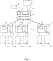
- Fig. 1 depicts a first embodiment for the system for providing redundant electric power to at least one vehicle component 10, 11.
- the system comprises one power management unit 3 connected to a vehicle power network 1 that may provide the power.
- status information can be provided to a vehicle communication network 2.
- the system comprises a plurality of storage units 7 that are coupled to the one power management unit 3 for receiving electric power to be stored in the storage units 7.
- the storage units 7 comprise at least one storage cell 9.
- the power management unit 3 comprises a charging unit 4 which is adapted to carry out the charging of the storage units 7.
- the power management unit 3 further comprises a logic circuit 5 that monitors the charging as well as determines status information about the storage units 7 (for example the charge level of the storage cells 9 within the storage units 7) and may provide this information to the vehicle communication network 2.
- the power management unit 3 finally comprises at least one switching unit 6 which is configured to interrupt the connection between the power management unit 3 to one or more of the storage cells 9. The interruption is controlled by the logic circuit 5 and ensures that in case of a malfunctioning, for example within the storage units 7, the respective storage unit 7 or at least the storage cell 9 can be disconnected from the system.
- each storage unit 7 may include a further logic circuit 8.
- Each of the storage units 7 or a subset thereof may comprise one or more terminals to connect vehicle components 10, 11 to the respective storage unit(s) 7.
- the vehicle components 10, 11 may relate to safety relevant vehicle components 10 and other vehicle components that consume the stored power.
- a safety relevant vehicle component 10 can be connected different storage units 7 so that even in case of a malfunctioning of one or some of the storage units 7, the power supply to the safety relevant vehicle component 10 can still be maintained.
- the logic circuits 5, 8 will replace the "missing" power through the other storage units 7 connected to the vehicle component 10.
- a safe power supply can be maintained up to a needed level.
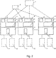
- Fig. 2 depicts another embodiment for the system for providing redundant electric power to the vehicle components 10, 11.
- each of the storage units 7 comprises its own, dedicated power management unit 3 that controls and monitors the charging and the charge level of the storage cells 9.
- the respective incorporated power management units 3 again comprise a switch 6 which is configured to disconnect the storage cell 9 from the system in order to provide a protection in case a malfunctioning occurs.
- the power management units 3 each comprises a logic circuit 5 for controlling the charging unit 4 and the switch 6.
- Each of the power management units 3 is connected to the vehicle power network 1 to receive power and to the communication network 2 in order to provide information about the charging state of the electric power supply.
- each or any of the storage units 7 comprise a respective logic circuit, because this function can be taken over by the logic circuit 5 being arranged in the power management unit 3 (also known as central unit). Likewise, it is possible that the function of the logic circuit 5 in the power management unit 3 can be taken over by a respective logic circuit arranged in the storage units 7 (not shown in Fig. 2 ).
- safety relevant vehicle components 10 can be connected to various storage cells 7 in order to ensure a redundant power supply to the safety relevant vehicle component(s) 10.
- the redundant voltage supply through the various terminals of the storage units 7 may also enable a supply for different voltage values.
- Both embodiments are powered by the electric board network 1 of the vehicle and can provide energy storage status information over a redundant vehicle communication network 2.
- the storage cells 9 need to be connected to the vehicle component(s) by respective terminals. Instead a grouping of storage units 7 or storage cells 9 can be arranged. For example, a connection can be provided between different storage units 7 to keep the voltages at the different storage units at the same or at a desired level. Likewise, an active charge balancing unit can be formed between the different storage units 7.
- the storage cells 9 can be any electrical component that is able to store electric energy and may include one or more battery cells.
- the power management unit(s) 3 in both embodiments is/are responsible for keeping a charge level of the energy storage cells 9 in each electric energy storage circuit at a target level to guarantee the availability for the safety relevant consumers 10. Moreover, the power management unit 3 is responsible for monitoring the energy storage and provides respective status information about the available energy and remaining functionality (for example the number or amount of remaining braking cycles or steering maneuvers that are still possible).
- the intelligent electric energy storage units 7 are responsible for providing energy for safety relevant consumers 10 and other consumers 11 - even on different/mixed voltage levels if needed. These voltage levels are produced from electrical components that store the potential energy.
- the further logic circuit 8 monitors the circuit outputs and charge levels of the storage components 9, collects the respective data and provides it to the power management unit 3. According to further embodiments, it is also possible to provide different voltage levels at the output terminals for different consumers (vehicle components) from the same circuit (the same power supply).
- the power management unit 3 and the storage units 7 may be combined within a common block and act together as in the embodiment of Fig. 1 .
- An advantage of the embodiment of Fig. 2 is the separation between the different storage units 7 together with the power management units 3. Hence, it prevents better any failure propagation through the system.
- the logic circuit 5 within these blocks provides a monitoring of the energy storage, the charge management and provides status information.
- the safety switches provide another advantage of embodiments, because they are able to separate immediately some or a single circuit or component in case of any failure or malfunctioning. As a result, the failure will not have an adverse effect on any other component and the system according to embodiments is actually a fail-operational power supply suitable in particular for safety relevant applications.
- the power supply according to embodiments is thus particularly suited as backup energy that can be provided to any safety relevant consumer in case any single failure occurs in the electric energy supply system.
Landscapes
- Engineering & Computer Science (AREA)
- Power Engineering (AREA)
- Mechanical Engineering (AREA)
- Transportation (AREA)
- Sustainable Energy (AREA)
- Sustainable Development (AREA)
- Life Sciences & Earth Sciences (AREA)
- Theoretical Computer Science (AREA)
- General Engineering & Computer Science (AREA)
- General Physics & Mathematics (AREA)
- Physics & Mathematics (AREA)
- Quality & Reliability (AREA)
- Business, Economics & Management (AREA)
- Emergency Management (AREA)
- Charge And Discharge Circuits For Batteries Or The Like (AREA)
- Electric Propulsion And Braking For Vehicles (AREA)
Priority Applications (7)
| Application Number | Priority Date | Filing Date | Title |
|---|---|---|---|
| EP18195131.0A EP3626505B1 (fr) | 2018-09-18 | 2018-09-18 | Système et procédé de fourniture d'énergie électrique redondante |
| HUE18195131A HUE070263T2 (hu) | 2018-09-18 | 2018-09-18 | Redundáns elektromos áram biztosítására szolgáló rendszer és módszer |
| CN201980061098.2A CN112714711B (zh) | 2018-09-18 | 2019-09-05 | 提供冗余电力的系统和方法 |
| US17/277,429 US11804727B2 (en) | 2018-09-18 | 2019-09-05 | System and method for providing redundant electric power |
| PCT/EP2019/073671 WO2020057989A1 (fr) | 2018-09-18 | 2019-09-05 | Système et procédé de fourniture d'une puissance électrique redondante |
| JP2021538915A JP7293364B2 (ja) | 2018-09-18 | 2019-09-05 | 冗長電力を供給するためのシステムおよび方法 |
| KR1020217009585A KR102593867B1 (ko) | 2018-09-18 | 2019-09-05 | 리던던트 전력 공급 시스템 및 방법 |
Applications Claiming Priority (1)
| Application Number | Priority Date | Filing Date | Title |
|---|---|---|---|
| EP18195131.0A EP3626505B1 (fr) | 2018-09-18 | 2018-09-18 | Système et procédé de fourniture d'énergie électrique redondante |
Publications (2)
| Publication Number | Publication Date |
|---|---|
| EP3626505A1 true EP3626505A1 (fr) | 2020-03-25 |
| EP3626505B1 EP3626505B1 (fr) | 2024-11-06 |
Family
ID=63642685
Family Applications (1)
| Application Number | Title | Priority Date | Filing Date |
|---|---|---|---|
| EP18195131.0A Active EP3626505B1 (fr) | 2018-09-18 | 2018-09-18 | Système et procédé de fourniture d'énergie électrique redondante |
Country Status (7)
| Country | Link |
|---|---|
| US (1) | US11804727B2 (fr) |
| EP (1) | EP3626505B1 (fr) |
| JP (1) | JP7293364B2 (fr) |
| KR (1) | KR102593867B1 (fr) |
| CN (1) | CN112714711B (fr) |
| HU (1) | HUE070263T2 (fr) |
| WO (1) | WO2020057989A1 (fr) |
Cited By (2)
| Publication number | Priority date | Publication date | Assignee | Title |
|---|---|---|---|---|
| EP4707095A1 (fr) | 2024-09-10 | 2026-03-11 | KB Intellectual Property GmbH & Co. KG | Système d'alimentation redondant pour systèmes de freinage électro-mécanique dans un véhicule |
| EP4707092A1 (fr) | 2024-09-10 | 2026-03-11 | KB Intellectual Property GmbH & Co. KG | Alimentation redondante améliorée pour systèmes de freinage électro-mécaniques dans un véhicule, de préférence dans un véhicule utilitaire |
Families Citing this family (3)
| Publication number | Priority date | Publication date | Assignee | Title |
|---|---|---|---|---|
| DE102019214720A1 (de) * | 2019-09-26 | 2021-04-01 | Robert Bosch Gmbh | Steuereinrichtung für ein Fahrzeug |
| EP4124494A1 (fr) * | 2021-07-30 | 2023-02-01 | KNORR-BREMSE Systeme für Nutzfahrzeuge GmbH | Système de fourniture d'énergie, procédé de fonctionnement de système de fourniture d'énergie et véhicule utilitaire doté d'un système de fourniture d'énergie avec système de communication redondante |
| CN119974985B (zh) * | 2025-03-25 | 2025-10-03 | 天津中环恒达科技有限公司 | 智能车载算力平台的冗余电源控制系统 |
Citations (4)
| Publication number | Priority date | Publication date | Assignee | Title |
|---|---|---|---|---|
| DE10053584A1 (de) | 2000-10-25 | 2002-05-02 | Volkswagen Ag | Redundante Spannungsversorgung für sicherheitsrelevante Verbraucher |
| WO2011161758A1 (fr) * | 2010-06-22 | 2011-12-29 | 日立オートモティブシステムズ株式会社 | Système d'alimentation électrique |
| CN202142875U (zh) * | 2011-05-03 | 2012-02-08 | 郑茂振 | 在线互动式直流转直流长效型备援电力系统 |
| DE102013218576A1 (de) | 2012-09-20 | 2014-03-20 | GM Global Technology Operations LLC (n. d. Ges. d. Staates Delaware) | Fehlerbetrieb-Stromversorgungssystem mit mehreren Energiespeichervorrichtungen |
Family Cites Families (36)
| Publication number | Priority date | Publication date | Assignee | Title |
|---|---|---|---|---|
| JPH04125033A (ja) | 1990-09-13 | 1992-04-24 | Nissan Motor Co Ltd | 2電圧バッテリ |
| US6104967A (en) | 1997-07-25 | 2000-08-15 | 3M Innovative Properties Company | Fault-tolerant battery system employing intra-battery network architecture |
| US6345225B1 (en) | 1997-11-22 | 2002-02-05 | Continental Teves Ag & Co., Ohg | Electromechanical brake system |
| DE19756976C2 (de) | 1997-12-20 | 2000-05-11 | Daimler Chrysler Ag | Bremseinrichtung für Fahrzeuge |
| DE10112514A1 (de) | 2000-12-22 | 2002-06-27 | Volkswagen Ag | X-by-wire-System für ein Fahrzeug |
| DE10144282A1 (de) | 2001-09-08 | 2003-03-27 | Vb Autobatterie Gmbh | Energieversorgungssystem mit zwei elektrischen Energiespeichern |
| DE10348162B3 (de) | 2003-10-17 | 2005-01-27 | Daimlerchrysler Ag | Vorrichtung zur redundanten Energieversorgung sicherheitsrelevanter Verbraucher |
| DE102005056962A1 (de) | 2005-11-30 | 2007-07-12 | Daimlerchrysler Ag | Verfahren zum Betrieb eines redundanten elektrischen Netzes |
| JP2007223471A (ja) | 2006-02-23 | 2007-09-06 | Toyota Motor Corp | 車両用電源制御装置 |
| US7605492B2 (en) * | 2006-04-21 | 2009-10-20 | Ford Global Technologies, Llc | Power supply system and method for supplying power to a vehicle |
| JP2008072880A (ja) | 2006-09-15 | 2008-03-27 | Toyota Motor Corp | 電源システム |
| JP2008179182A (ja) | 2007-01-23 | 2008-08-07 | Toyota Motor Corp | 電源制御装置および電源制御方法 |
| DE102010048985A1 (de) | 2010-10-20 | 2012-04-26 | Li-Tec Battery Gmbh | Batteriemanagementsystem für Stromversorgungssystem mit Niederspannungsbereich und Hochspannungsbereich |
| CN103166303A (zh) * | 2011-12-09 | 2013-06-19 | 台达电子工业股份有限公司 | 电能管理装置及其操作方法 |
| CA2765945A1 (fr) * | 2012-01-30 | 2013-07-30 | Hydro-Quebec | Systeme de gestion de batterie d'un vehicule electrique avec detection de subtilisation d'energie |
| US9008879B2 (en) * | 2012-07-05 | 2015-04-14 | General Electric Company | System and method for operating a hybrid vehicle system |
| US9669724B2 (en) * | 2012-08-31 | 2017-06-06 | Johnson Controls Technology Center | Optimized fuzzy logic controller for energy management in micro and mild hybrid electric vehicles |
| DE102012217184A1 (de) | 2012-09-24 | 2014-06-12 | Bayerische Motoren Werke Aktiengesellschaft | Energiemanagement für Kraftfahrzeug mit Koppelspeichervorrichtung |
| DE102012021564B4 (de) | 2012-11-02 | 2025-11-13 | Volkswagen Aktiengesellschaft | Vorrichtung und Verfahren zum teil-, hoch- oder vollautomatischen Führen eines Kraftfahrzeuges |
| US10106038B2 (en) | 2012-12-28 | 2018-10-23 | Johnson Controls Technology Company | Dual function battery system and method |
| US20140265554A1 (en) * | 2013-03-14 | 2014-09-18 | Ford Global Technologies, Llc | Dual Lithium-Ion Battery System for Electric Vehicles |
| DE102013225020A1 (de) | 2013-12-05 | 2015-06-11 | Robert Bosch Gmbh | Bordnetz zur fehlertoleranten und redundanten Versorgung |
| US9457684B2 (en) | 2014-03-26 | 2016-10-04 | Ford Global Technologies, Llc | Redundant electrical power for autonomous vehicles |
| DE102014214103A1 (de) | 2014-07-21 | 2016-01-21 | Robert Bosch Gmbh | Vorrichtung zur Versorgung zumindest eines Verbrauchers |
| DE102014219133A1 (de) | 2014-09-23 | 2016-03-24 | Robert Bosch Gmbh | Bordnetz |
| US20160134160A1 (en) | 2014-11-07 | 2016-05-12 | Schneider Electric It Corporation | Systems and methods for battery management |
| JP5977855B1 (ja) | 2015-03-31 | 2016-08-24 | 富士重工業株式会社 | 車両用電源装置 |
| JP6468138B2 (ja) | 2015-09-10 | 2019-02-13 | 株式会社デンソー | 電源装置 |
| DE102015222545A1 (de) | 2015-11-16 | 2017-05-18 | Robert Bosch Gmbh | Bordnetz |
| JP6266670B2 (ja) * | 2016-02-12 | 2018-01-24 | 本田技研工業株式会社 | 電力供給システム及び輸送機器、並びに、電力伝送方法 |
| CN205706212U (zh) | 2016-04-08 | 2016-11-23 | 同济大学 | 集中式架构控制器及供电冗余的电动智能汽车电气系统 |
| CN105857102B (zh) * | 2016-04-08 | 2017-12-15 | 同济大学 | 集中式架构控制器及供电冗余的电动智能汽车电气系统 |
| JP6902201B2 (ja) | 2016-10-04 | 2021-07-14 | 株式会社Gsユアサ | 車両の電源装置 |
| US10407003B2 (en) | 2017-02-16 | 2019-09-10 | Ford Global Technologies, Llc | Short-circuit protection for vehicle redundant power architecture |
| DE102017002113A1 (de) * | 2017-03-08 | 2018-09-13 | Thyssenkrupp Ag | Unterseeboot und Verfahren zum Betreiben eines Antriebssystems eines Unterseebootes |
| DE102017104958B4 (de) * | 2017-03-09 | 2024-03-14 | Dr. Ing. H.C. F. Porsche Aktiengesellschaft | Batteriespeichersystem |
-
2018
- 2018-09-18 EP EP18195131.0A patent/EP3626505B1/fr active Active
- 2018-09-18 HU HUE18195131A patent/HUE070263T2/hu unknown
-
2019
- 2019-09-05 KR KR1020217009585A patent/KR102593867B1/ko active Active
- 2019-09-05 US US17/277,429 patent/US11804727B2/en active Active
- 2019-09-05 CN CN201980061098.2A patent/CN112714711B/zh active Active
- 2019-09-05 WO PCT/EP2019/073671 patent/WO2020057989A1/fr not_active Ceased
- 2019-09-05 JP JP2021538915A patent/JP7293364B2/ja active Active
Patent Citations (4)
| Publication number | Priority date | Publication date | Assignee | Title |
|---|---|---|---|---|
| DE10053584A1 (de) | 2000-10-25 | 2002-05-02 | Volkswagen Ag | Redundante Spannungsversorgung für sicherheitsrelevante Verbraucher |
| WO2011161758A1 (fr) * | 2010-06-22 | 2011-12-29 | 日立オートモティブシステムズ株式会社 | Système d'alimentation électrique |
| CN202142875U (zh) * | 2011-05-03 | 2012-02-08 | 郑茂振 | 在线互动式直流转直流长效型备援电力系统 |
| DE102013218576A1 (de) | 2012-09-20 | 2014-03-20 | GM Global Technology Operations LLC (n. d. Ges. d. Staates Delaware) | Fehlerbetrieb-Stromversorgungssystem mit mehreren Energiespeichervorrichtungen |
Cited By (2)
| Publication number | Priority date | Publication date | Assignee | Title |
|---|---|---|---|---|
| EP4707095A1 (fr) | 2024-09-10 | 2026-03-11 | KB Intellectual Property GmbH & Co. KG | Système d'alimentation redondant pour systèmes de freinage électro-mécanique dans un véhicule |
| EP4707092A1 (fr) | 2024-09-10 | 2026-03-11 | KB Intellectual Property GmbH & Co. KG | Alimentation redondante améliorée pour systèmes de freinage électro-mécaniques dans un véhicule, de préférence dans un véhicule utilitaire |
Also Published As
| Publication number | Publication date |
|---|---|
| CN112714711A (zh) | 2021-04-27 |
| JP7293364B2 (ja) | 2023-06-19 |
| CN112714711B (zh) | 2024-02-20 |
| KR20210052521A (ko) | 2021-05-10 |
| EP3626505B1 (fr) | 2024-11-06 |
| JP2021535874A (ja) | 2021-12-23 |
| WO2020057989A1 (fr) | 2020-03-26 |
| KR102593867B1 (ko) | 2023-10-25 |
| US11804727B2 (en) | 2023-10-31 |
| HUE070263T2 (hu) | 2025-05-28 |
| US20220037913A1 (en) | 2022-02-03 |
Similar Documents
| Publication | Publication Date | Title |
|---|---|---|
| US11804727B2 (en) | System and method for providing redundant electric power | |
| US10938233B2 (en) | Battery storage system and on-board electrical system for supplying power in a fault-tolerant manner to safety-relevant loads in a vehicle | |
| US10838474B2 (en) | Electric power supply system | |
| CN108495771A (zh) | 车载电源用的开关装置及车载用的电源装置 | |
| US20130249278A1 (en) | Battery system and method of operating the battery system | |
| CN110254288A (zh) | 电池包控制系统 | |
| CN115320377A (zh) | 用于车辆的电力系统 | |
| EP3621173B1 (fr) | Dispositif et procédé d'égalisation et de précharge de modules de piles | |
| US20220024396A1 (en) | Protection Circuitry and a Method for Protecting a Vehicle Power Supply | |
| CN112714989B (zh) | 电源和用于供电的方法 | |
| US12365249B2 (en) | System and a method for providing electric power | |
| US20240343154A1 (en) | Energy Supply Module and Energy Supply Management System | |
| EP4686028A2 (fr) | Dispositif d'alimentation redondant | |
| US20250096581A1 (en) | Battery power supply architecture | |
| CN119675185A (zh) | 供电控制系统、方法及电子设备 | |
| CN117416532A (zh) | 基于供电优先级的主备独立、分区控制的卫星配电方法 | |
| CN110999017A (zh) | 用于飞行器的电能储存系统 | |
| HK1189302B (en) | Battery system and method of operating the battery system | |
| HK1147851A1 (en) | Fault tolerant modular battery management system |
Legal Events
| Date | Code | Title | Description |
|---|---|---|---|
| PUAI | Public reference made under article 153(3) epc to a published international application that has entered the european phase |
Free format text: ORIGINAL CODE: 0009012 |
|
| STAA | Information on the status of an ep patent application or granted ep patent |
Free format text: STATUS: THE APPLICATION HAS BEEN PUBLISHED |
|
| AK | Designated contracting states |
Kind code of ref document: A1 Designated state(s): AL AT BE BG CH CY CZ DE DK EE ES FI FR GB GR HR HU IE IS IT LI LT LU LV MC MK MT NL NO PL PT RO RS SE SI SK SM TR |
|
| AX | Request for extension of the european patent |
Extension state: BA ME |
|
| STAA | Information on the status of an ep patent application or granted ep patent |
Free format text: STATUS: REQUEST FOR EXAMINATION WAS MADE |
|
| 17P | Request for examination filed |
Effective date: 20200917 |
|
| RBV | Designated contracting states (corrected) |
Designated state(s): AL AT BE BG CH CY CZ DE DK EE ES FI FR GB GR HR HU IE IS IT LI LT LU LV MC MK MT NL NO PL PT RO RS SE SI SK SM TR |
|
| STAA | Information on the status of an ep patent application or granted ep patent |
Free format text: STATUS: EXAMINATION IS IN PROGRESS |
|
| 17Q | First examination report despatched |
Effective date: 20211130 |
|
| GRAP | Despatch of communication of intention to grant a patent |
Free format text: ORIGINAL CODE: EPIDOSNIGR1 |
|
| STAA | Information on the status of an ep patent application or granted ep patent |
Free format text: STATUS: GRANT OF PATENT IS INTENDED |
|
| INTG | Intention to grant announced |
Effective date: 20240522 |
|
| GRAS | Grant fee paid |
Free format text: ORIGINAL CODE: EPIDOSNIGR3 |
|
| GRAA | (expected) grant |
Free format text: ORIGINAL CODE: 0009210 |
|
| STAA | Information on the status of an ep patent application or granted ep patent |
Free format text: STATUS: THE PATENT HAS BEEN GRANTED |
|
| AK | Designated contracting states |
Kind code of ref document: B1 Designated state(s): AL AT BE BG CH CY CZ DE DK EE ES FI FR GB GR HR HU IE IS IT LI LT LU LV MC MK MT NL NO PL PT RO RS SE SI SK SM TR |
|
| REG | Reference to a national code |
Ref country code: GB Ref legal event code: FG4D |
|
| REG | Reference to a national code |
Ref country code: CH Ref legal event code: EP |
|
| REG | Reference to a national code |
Ref country code: DE Ref legal event code: R096 Ref document number: 602018076205 Country of ref document: DE |
|
| REG | Reference to a national code |
Ref country code: IE Ref legal event code: FG4D |
|
| REG | Reference to a national code |
Ref country code: SE Ref legal event code: TRGR |
|
| P01 | Opt-out of the competence of the unified patent court (upc) registered |
Free format text: CASE NUMBER: APP_1576/2025 Effective date: 20250110 |
|
| REG | Reference to a national code |
Ref country code: LT Ref legal event code: MG9D |
|
| REG | Reference to a national code |
Ref country code: NL Ref legal event code: MP Effective date: 20241106 |
|
| PG25 | Lapsed in a contracting state [announced via postgrant information from national office to epo] |
Ref country code: HR Free format text: LAPSE BECAUSE OF FAILURE TO SUBMIT A TRANSLATION OF THE DESCRIPTION OR TO PAY THE FEE WITHIN THE PRESCRIBED TIME-LIMIT Effective date: 20241106 Ref country code: IS Free format text: LAPSE BECAUSE OF FAILURE TO SUBMIT A TRANSLATION OF THE DESCRIPTION OR TO PAY THE FEE WITHIN THE PRESCRIBED TIME-LIMIT Effective date: 20250306 Ref country code: PT Free format text: LAPSE BECAUSE OF FAILURE TO SUBMIT A TRANSLATION OF THE DESCRIPTION OR TO PAY THE FEE WITHIN THE PRESCRIBED TIME-LIMIT Effective date: 20250306 |
|
| PG25 | Lapsed in a contracting state [announced via postgrant information from national office to epo] |
Ref country code: FI Free format text: LAPSE BECAUSE OF FAILURE TO SUBMIT A TRANSLATION OF THE DESCRIPTION OR TO PAY THE FEE WITHIN THE PRESCRIBED TIME-LIMIT Effective date: 20241106 Ref country code: NL Free format text: LAPSE BECAUSE OF FAILURE TO SUBMIT A TRANSLATION OF THE DESCRIPTION OR TO PAY THE FEE WITHIN THE PRESCRIBED TIME-LIMIT Effective date: 20241106 |
|
| REG | Reference to a national code |
Ref country code: AT Ref legal event code: MK05 Ref document number: 1739027 Country of ref document: AT Kind code of ref document: T Effective date: 20241106 |
|
| PG25 | Lapsed in a contracting state [announced via postgrant information from national office to epo] |
Ref country code: BG Free format text: LAPSE BECAUSE OF FAILURE TO SUBMIT A TRANSLATION OF THE DESCRIPTION OR TO PAY THE FEE WITHIN THE PRESCRIBED TIME-LIMIT Effective date: 20241106 |
|
| PG25 | Lapsed in a contracting state [announced via postgrant information from national office to epo] |
Ref country code: ES Free format text: LAPSE BECAUSE OF FAILURE TO SUBMIT A TRANSLATION OF THE DESCRIPTION OR TO PAY THE FEE WITHIN THE PRESCRIBED TIME-LIMIT Effective date: 20241106 |
|
| PG25 | Lapsed in a contracting state [announced via postgrant information from national office to epo] |
Ref country code: NO Free format text: LAPSE BECAUSE OF FAILURE TO SUBMIT A TRANSLATION OF THE DESCRIPTION OR TO PAY THE FEE WITHIN THE PRESCRIBED TIME-LIMIT Effective date: 20250206 |
|
| PG25 | Lapsed in a contracting state [announced via postgrant information from national office to epo] |
Ref country code: LV Free format text: LAPSE BECAUSE OF FAILURE TO SUBMIT A TRANSLATION OF THE DESCRIPTION OR TO PAY THE FEE WITHIN THE PRESCRIBED TIME-LIMIT Effective date: 20241106 Ref country code: GR Free format text: LAPSE BECAUSE OF FAILURE TO SUBMIT A TRANSLATION OF THE DESCRIPTION OR TO PAY THE FEE WITHIN THE PRESCRIBED TIME-LIMIT Effective date: 20250207 Ref country code: AT Free format text: LAPSE BECAUSE OF FAILURE TO SUBMIT A TRANSLATION OF THE DESCRIPTION OR TO PAY THE FEE WITHIN THE PRESCRIBED TIME-LIMIT Effective date: 20241106 |
|
| PG25 | Lapsed in a contracting state [announced via postgrant information from national office to epo] |
Ref country code: PL Free format text: LAPSE BECAUSE OF FAILURE TO SUBMIT A TRANSLATION OF THE DESCRIPTION OR TO PAY THE FEE WITHIN THE PRESCRIBED TIME-LIMIT Effective date: 20241106 |
|
| PG25 | Lapsed in a contracting state [announced via postgrant information from national office to epo] |
Ref country code: RS Free format text: LAPSE BECAUSE OF FAILURE TO SUBMIT A TRANSLATION OF THE DESCRIPTION OR TO PAY THE FEE WITHIN THE PRESCRIBED TIME-LIMIT Effective date: 20250206 |
|
| REG | Reference to a national code |
Ref country code: HU Ref legal event code: AG4A Ref document number: E070263 Country of ref document: HU |
|
| PG25 | Lapsed in a contracting state [announced via postgrant information from national office to epo] |
Ref country code: SM Free format text: LAPSE BECAUSE OF FAILURE TO SUBMIT A TRANSLATION OF THE DESCRIPTION OR TO PAY THE FEE WITHIN THE PRESCRIBED TIME-LIMIT Effective date: 20241106 |
|
| PG25 | Lapsed in a contracting state [announced via postgrant information from national office to epo] |
Ref country code: DK Free format text: LAPSE BECAUSE OF FAILURE TO SUBMIT A TRANSLATION OF THE DESCRIPTION OR TO PAY THE FEE WITHIN THE PRESCRIBED TIME-LIMIT Effective date: 20241106 |
|
| PG25 | Lapsed in a contracting state [announced via postgrant information from national office to epo] |
Ref country code: EE Free format text: LAPSE BECAUSE OF FAILURE TO SUBMIT A TRANSLATION OF THE DESCRIPTION OR TO PAY THE FEE WITHIN THE PRESCRIBED TIME-LIMIT Effective date: 20241106 |
|
| PG25 | Lapsed in a contracting state [announced via postgrant information from national office to epo] |
Ref country code: RO Free format text: LAPSE BECAUSE OF FAILURE TO SUBMIT A TRANSLATION OF THE DESCRIPTION OR TO PAY THE FEE WITHIN THE PRESCRIBED TIME-LIMIT Effective date: 20241106 |
|
| PG25 | Lapsed in a contracting state [announced via postgrant information from national office to epo] |
Ref country code: SK Free format text: LAPSE BECAUSE OF FAILURE TO SUBMIT A TRANSLATION OF THE DESCRIPTION OR TO PAY THE FEE WITHIN THE PRESCRIBED TIME-LIMIT Effective date: 20241106 |
|
| PG25 | Lapsed in a contracting state [announced via postgrant information from national office to epo] |
Ref country code: CZ Free format text: LAPSE BECAUSE OF FAILURE TO SUBMIT A TRANSLATION OF THE DESCRIPTION OR TO PAY THE FEE WITHIN THE PRESCRIBED TIME-LIMIT Effective date: 20241106 |
|
| PG25 | Lapsed in a contracting state [announced via postgrant information from national office to epo] |
Ref country code: IT Free format text: LAPSE BECAUSE OF FAILURE TO SUBMIT A TRANSLATION OF THE DESCRIPTION OR TO PAY THE FEE WITHIN THE PRESCRIBED TIME-LIMIT Effective date: 20241106 |
|
| REG | Reference to a national code |
Ref country code: DE Ref legal event code: R026 Ref document number: 602018076205 Country of ref document: DE |
|
| PLBI | Opposition filed |
Free format text: ORIGINAL CODE: 0009260 |
|
| 26 | Opposition filed |
Opponent name: ZF CV SYSTEMS GLOBAL GMBH Effective date: 20250806 |
|
| PLAX | Notice of opposition and request to file observation + time limit sent |
Free format text: ORIGINAL CODE: EPIDOSNOBS2 |
|
| PGFP | Annual fee paid to national office [announced via postgrant information from national office to epo] |
Ref country code: DE Payment date: 20250926 Year of fee payment: 8 |
|
| PGFP | Annual fee paid to national office [announced via postgrant information from national office to epo] |
Ref country code: HU Payment date: 20250912 Year of fee payment: 8 Ref country code: GB Payment date: 20250923 Year of fee payment: 8 |
|
| PGFP | Annual fee paid to national office [announced via postgrant information from national office to epo] |
Ref country code: FR Payment date: 20250924 Year of fee payment: 8 |
|
| PGFP | Annual fee paid to national office [announced via postgrant information from national office to epo] |
Ref country code: SE Payment date: 20250924 Year of fee payment: 8 |
|
| PLBB | Reply of patent proprietor to notice(s) of opposition received |
Free format text: ORIGINAL CODE: EPIDOSNOBS3 |