EP3626523B1 - Siège de véhicule pour cabines des véhicules utilitaires - Google Patents
Siège de véhicule pour cabines des véhicules utilitaires Download PDFInfo
- Publication number
- EP3626523B1 EP3626523B1 EP19197240.5A EP19197240A EP3626523B1 EP 3626523 B1 EP3626523 B1 EP 3626523B1 EP 19197240 A EP19197240 A EP 19197240A EP 3626523 B1 EP3626523 B1 EP 3626523B1
- Authority
- EP
- European Patent Office
- Prior art keywords
- axis
- along
- vehicle seat
- backrest
- seat
- Prior art date
- Legal status (The legal status is an assumption and is not a legal conclusion. Google has not performed a legal analysis and makes no representation as to the accuracy of the status listed.)
- Active
Links
Images


Classifications
-
- B—PERFORMING OPERATIONS; TRANSPORTING
- B60—VEHICLES IN GENERAL
- B60N—SEATS SPECIALLY ADAPTED FOR VEHICLES; VEHICLE PASSENGER ACCOMMODATION NOT OTHERWISE PROVIDED FOR
- B60N2/00—Seats specially adapted for vehicles; Arrangement or mounting of seats in vehicles
- B60N2/64—Back-rests or cushions
- B60N2/643—Back-rests or cushions shape of the back-rests
-
- B—PERFORMING OPERATIONS; TRANSPORTING
- B60—VEHICLES IN GENERAL
- B60N—SEATS SPECIALLY ADAPTED FOR VEHICLES; VEHICLE PASSENGER ACCOMMODATION NOT OTHERWISE PROVIDED FOR
- B60N2/00—Seats specially adapted for vehicles; Arrangement or mounting of seats in vehicles
- B60N2/02—Seats specially adapted for vehicles; Arrangement or mounting of seats in vehicles the seat or part thereof being movable, e.g. adjustable
- B60N2/04—Seats specially adapted for vehicles; Arrangement or mounting of seats in vehicles the seat or part thereof being movable, e.g. adjustable the whole seat being movable
- B60N2/06—Seats specially adapted for vehicles; Arrangement or mounting of seats in vehicles the seat or part thereof being movable, e.g. adjustable the whole seat being movable slidable
-
- B—PERFORMING OPERATIONS; TRANSPORTING
- B60—VEHICLES IN GENERAL
- B60N—SEATS SPECIALLY ADAPTED FOR VEHICLES; VEHICLE PASSENGER ACCOMMODATION NOT OTHERWISE PROVIDED FOR
- B60N2/00—Seats specially adapted for vehicles; Arrangement or mounting of seats in vehicles
- B60N2/02—Seats specially adapted for vehicles; Arrangement or mounting of seats in vehicles the seat or part thereof being movable, e.g. adjustable
- B60N2/20—Seats specially adapted for vehicles; Arrangement or mounting of seats in vehicles the seat or part thereof being movable, e.g. adjustable the back-rest being tiltable, e.g. to permit easy access
- B60N2/206—Seats specially adapted for vehicles; Arrangement or mounting of seats in vehicles the seat or part thereof being movable, e.g. adjustable the back-rest being tiltable, e.g. to permit easy access to a position in which it can be used as a support for objects, e.g. as a tray
-
- B—PERFORMING OPERATIONS; TRANSPORTING
- B60—VEHICLES IN GENERAL
- B60N—SEATS SPECIALLY ADAPTED FOR VEHICLES; VEHICLE PASSENGER ACCOMMODATION NOT OTHERWISE PROVIDED FOR
- B60N2/00—Seats specially adapted for vehicles; Arrangement or mounting of seats in vehicles
- B60N2/02—Seats specially adapted for vehicles; Arrangement or mounting of seats in vehicles the seat or part thereof being movable, e.g. adjustable
- B60N2/22—Seats specially adapted for vehicles; Arrangement or mounting of seats in vehicles the seat or part thereof being movable, e.g. adjustable the back-rest being adjustable
-
- B—PERFORMING OPERATIONS; TRANSPORTING
- B60—VEHICLES IN GENERAL
- B60N—SEATS SPECIALLY ADAPTED FOR VEHICLES; VEHICLE PASSENGER ACCOMMODATION NOT OTHERWISE PROVIDED FOR
- B60N2/00—Seats specially adapted for vehicles; Arrangement or mounting of seats in vehicles
- B60N2/24—Seats specially adapted for vehicles; Arrangement or mounting of seats in vehicles for particular purposes or particular vehicles
- B60N2/30—Non-dismountable or dismountable seats storable in a non-use position, e.g. foldable spare seats
- B60N2/3002—Non-dismountable or dismountable seats storable in a non-use position, e.g. foldable spare seats back-rest movements
- B60N2/3004—Non-dismountable or dismountable seats storable in a non-use position, e.g. foldable spare seats back-rest movements by rotation only
- B60N2/3009—Non-dismountable or dismountable seats storable in a non-use position, e.g. foldable spare seats back-rest movements by rotation only about transversal axis
- B60N2/3011—Non-dismountable or dismountable seats storable in a non-use position, e.g. foldable spare seats back-rest movements by rotation only about transversal axis the back-rest being hinged on the cushion, e.g. "portefeuille movement"
-
- B—PERFORMING OPERATIONS; TRANSPORTING
- B60—VEHICLES IN GENERAL
- B60N—SEATS SPECIALLY ADAPTED FOR VEHICLES; VEHICLE PASSENGER ACCOMMODATION NOT OTHERWISE PROVIDED FOR
- B60N2/00—Seats specially adapted for vehicles; Arrangement or mounting of seats in vehicles
- B60N2/64—Back-rests or cushions
-
- B—PERFORMING OPERATIONS; TRANSPORTING
- B60—VEHICLES IN GENERAL
- B60N—SEATS SPECIALLY ADAPTED FOR VEHICLES; VEHICLE PASSENGER ACCOMMODATION NOT OTHERWISE PROVIDED FOR
- B60N2/00—Seats specially adapted for vehicles; Arrangement or mounting of seats in vehicles
- B60N2/68—Seat frames
-
- B—PERFORMING OPERATIONS; TRANSPORTING
- B60—VEHICLES IN GENERAL
- B60N—SEATS SPECIALLY ADAPTED FOR VEHICLES; VEHICLE PASSENGER ACCOMMODATION NOT OTHERWISE PROVIDED FOR
- B60N2/00—Seats specially adapted for vehicles; Arrangement or mounting of seats in vehicles
- B60N2/80—Head-rests
- B60N2/806—Head-rests movable or adjustable
- B60N2/809—Head-rests movable or adjustable vertically slidable
- B60N2/812—Head-rests movable or adjustable vertically slidable characterised by their locking devices
- B60N2/821—Head-rests movable or adjustable vertically slidable characterised by their locking devices with continuous positioning
-
- B—PERFORMING OPERATIONS; TRANSPORTING
- B60—VEHICLES IN GENERAL
- B60N—SEATS SPECIALLY ADAPTED FOR VEHICLES; VEHICLE PASSENGER ACCOMMODATION NOT OTHERWISE PROVIDED FOR
- B60N2/00—Seats specially adapted for vehicles; Arrangement or mounting of seats in vehicles
- B60N2/80—Head-rests
- B60N2/806—Head-rests movable or adjustable
- B60N2/809—Head-rests movable or adjustable vertically slidable
- B60N2/832—Head-rests movable or adjustable vertically slidable movable to an inoperative or stowed position
-
- B—PERFORMING OPERATIONS; TRANSPORTING
- B60—VEHICLES IN GENERAL
- B60N—SEATS SPECIALLY ADAPTED FOR VEHICLES; VEHICLE PASSENGER ACCOMMODATION NOT OTHERWISE PROVIDED FOR
- B60N2/00—Seats specially adapted for vehicles; Arrangement or mounting of seats in vehicles
- B60N2/80—Head-rests
- B60N2/806—Head-rests movable or adjustable
- B60N2/838—Tiltable
- B60N2/856—Tiltable movable to an inoperative or stowed position
-
- B—PERFORMING OPERATIONS; TRANSPORTING
- B60—VEHICLES IN GENERAL
- B60N—SEATS SPECIALLY ADAPTED FOR VEHICLES; VEHICLE PASSENGER ACCOMMODATION NOT OTHERWISE PROVIDED FOR
- B60N2/00—Seats specially adapted for vehicles; Arrangement or mounting of seats in vehicles
- B60N2/90—Details or parts not otherwise provided for
- B60N2/919—Positioning and locking mechanisms
-
- B—PERFORMING OPERATIONS; TRANSPORTING
- B60—VEHICLES IN GENERAL
- B60N—SEATS SPECIALLY ADAPTED FOR VEHICLES; VEHICLE PASSENGER ACCOMMODATION NOT OTHERWISE PROVIDED FOR
- B60N2/00—Seats specially adapted for vehicles; Arrangement or mounting of seats in vehicles
- B60N2/02—Seats specially adapted for vehicles; Arrangement or mounting of seats in vehicles the seat or part thereof being movable, e.g. adjustable
- B60N2002/0204—Seats specially adapted for vehicles; Arrangement or mounting of seats in vehicles the seat or part thereof being movable, e.g. adjustable characterised by the seat or seat part turning about or moving along a non-standard, particular axis, i.e. an axis different from the axis characterising the conventional movement
- B60N2002/0216—Seats specially adapted for vehicles; Arrangement or mounting of seats in vehicles the seat or part thereof being movable, e.g. adjustable characterised by the seat or seat part turning about or moving along a non-standard, particular axis, i.e. an axis different from the axis characterising the conventional movement the seat or seat part turning about or moving along a transversal axis
Definitions
- the invention relates to a vehicle seat with an extension along a height axis Z and a width axis Y, comprising a seat part and a backrest element, which extends along a height axis Z 'and in a width axis Y'.
- Vehicle seats with backrest elements are well known from the prior art. In commercial vehicle cabins it is often desirable that their interior can be used in the most varied of ways, for example to provide a place to sleep or a place to cook. Often, however, in commercial vehicle cabs that are built in series, the available interior area is spatially limited. The vehicle seats, in particular the front passenger seat, should therefore be stowable or collapsible to save space.
- the vehicle seats have as little weight as possible in order to reduce the weight of the utility vehicle.
- the vehicle seats should also be able to be manufactured as cheaply as possible, without impairing the stability and safety requirements.
- the pamphlet DE 10 2009 033883 A1 discloses a vehicle seat with a backrest which has a supporting strut structure at least in a laterally central region for at least one cushion part supporting the seat user.
- This strut structure comprises an upwardly projecting support element which is arranged on a support part.
- the support part has a base part which extends in the transverse direction of the vehicle and which is arranged on a seat part so as to be pivotable about a pivot axis.
- the pamphlet EP 2 873 555 A1 shows a vehicle seat comprising a seat substructure.
- the seat substructure has a displacement device in the form of a rail system.
- a seat cushion is arranged on the seat substructure in such a way that it can be tilted in the vertical direction by means of a lifting device.
- a backrest is arranged on the seat substructure.
- a centrally arranged support arrangement is arranged on a tubular element which extends along the width axis and is connected to the seat substructure.
- the support arrangement comprises a main element and a movable element which is displaceable along the height direction relative to the main element and on which the backrest element is arranged.
- the object of the present invention is therefore to provide a vehicle seat which solves the problems described above.
- the vehicle seat according to the invention with an extension along a height axis Z and a width axis Y comprises a seat part and a backrest element which extends along a height axis Z ′ and in a width axis Y ′.
- the backrest element has a central structure extending along the height direction Z1, which is arranged centrally along the width axis Y 'and opens into a base structure extending essentially along the width axis Y', the backrest element having at least one stability element which extends along the Latitude axis Y 'extends away from the central structure, the base structure being pivotably arranged in a support structure of the vehicle site, so that the backrest element is pivotable about a first pivot axis, the first pivot axis being spaced from the seat part along a height axis Z of the vehicle seat.
- the vehicle seat according to the invention can be provided as a driver's seat or as a passenger seat.
- the vehicle seat thus extends along a height axis Z, a width axis Y and a depth axis X. Two directions are to be assigned to the respective axes.
- the height axis Z thus includes the directions Z1 (upwards) and Z2 (downwards).
- the latitude axis Y includes the directions Y1 (to the right) and Y2 (to the left).
- the depth axis X includes the directions X1 (forward) and X2 (backward).
- the backrest element extends along a height axis Z ', a width axis Y' and a depth axis X '. Two directions can also be assigned to these respective axes.
- the height axis Z 'thus comprises the directions Z'1 (upwards) and Z'2 (downwards).
- the latitude axis Y ' comprises the directions Y'1 (to the right) and Y'2 (to the left).
- the depth axis X ' includes the directions X'1 (forward) and X'2 (backward).
- the axes Z, Y, X of the vehicle seat or the assigned directions would be parallel to the axes Z ', Y', X 'of the backrest element, or to the correspondingly assigned directions.
- the height axis of the vehicle seat and the height axis of the backrest element would enclose an angle ⁇ which is preferably greater than 0 ° and preferably less than ⁇ 90 °.
- the angle ⁇ would therefore be in the interval] 0 °, ⁇ 90 °].
- the depth axes X and X ' would also enclose a corresponding angle.
- a stability element is understood to mean elements that serve to support / stabilize the person in the seat.
- Such stability elements can, for example, be struts, strut elements or plate-like elements.
- the stability elements can preferably be provided to support certain body regions. For example, the lower back or the lumbar region, the upper back or the shoulder region and the head can be supported.
- the stability elements extend away from the central structure or also the longitudinal structure.
- This central structure can advantageously be applied to the stability elements absorb acting forces and introduce them into the basic structure, since this force-absorbing central structure is based on the basic structure.
- the basic structure is firmly connected to the force-absorbing central structure, or formed integrally with it. "Integrally formed” is to be understood as meaning that the two elements are formed in one piece or in one piece.
- the basic structure can be firmly connected to the central structure, for example, by means of a fixation, for example by means of a screw connection, a plug connection, a rivet connection or a welded connection.
- the first pivot axis advantageously runs at least in sections through the base structure and the holding structure.
- the centrally arranged rear central structure is supported on the underside on a pivot axis which is preferably horizontal or aligned along the width axis Y of the vehicle seat or based on the horizontal or the width axis Y.
- this rear central structure / longitudinal structure and the pivot axis are suitable for pivoting the backrest forwards and backwards, whereby it is crucial that this pivot axis increases in relation to the seat part in the support structure, which extends upwards from the seat part in its rear extends, is arranged.
- the first pivot axis is spaced apart from the seat part in a vertical direction Z of the vehicle seat.
- the pivot axis preferably runs at least in sections through the basic structure. Accordingly, it is also preferred that the base structure is at a distance from the seat part.
- the distance between the pivot axis and the seat part is advantageously dimensioned such that the pivot axis is located in the region of the lumbar spine.
- the seat part advantageously comprises a cushion element on which the person sits. Furthermore, the seat part can comprise a corresponding receiving element which receives or holds the upholstery element. It is also advantageous if the backrest element is provided with at least one cushion element. The at least one cushion element is preferably held by the at least one stability element. The backrest element and the at least one cushion element therefore advantageously form the backrest of the vehicle seat. Of course, it would also be conceivable for a cushion element to be provided neither on the seat part nor on the backrest element. Accordingly, only a seat or a support surface would be provided, which contact the user.
- a first distance between the pivot axis and the seat part corresponds to at least a second distance that exists between the cushion surface in a lower third of the back surface and the pivot axis.
- the first distance is based on the surface of the seat part which is in contact with the user, which is advantageously the surface of the corresponding upholstery element.
- Such a configuration of the first spacing makes it possible to pivot the backrest or the backrest element forward by -90 °.
- the central structure would then be arranged essentially parallel to the seat part.
- the height axis Z 'of the backrest element would be arranged essentially parallel to the depth axis of the vehicle seat.
- the expression “essentially” is to be understood as meaning a slight tolerance deviation.
- Such a deviation from the parallelism of the elements or axes mentioned can be in a range from 0 ° to 10 °, preferably in a range between 0 ° and 7.5 °, more preferably in a range from 0 ° to 5 °.
- the vehicle seat can be stowed in a particularly space-saving manner thanks to the backrest element arranged essentially parallel to the seat part.
- An advantageous passenger vehicle seat or driver's seat can accordingly be stowed in the folded-down state in the rear area of the utility vehicle cabin in a space-saving manner.
- an increased space requirement can be made available in the front area of the utility vehicle cabin, for example for setting up a table for taking a meal.
- Such an advantageous passenger or driver seat can be changed in such a way that the entire backrest element can be folded down except for the seat part, so that a rear side of the backrest element is arranged almost horizontally.
- This vehicle seat can then preferably be moved backwards in the folded-in state.
- a guide system can advantageously be provided for this purpose.
- This guide system can advantageously comprise rails or rails placed on the body floor. It is advantageous that for this purpose the seat has rail elements or roller elements or sliding blocks or the like of complementary design on its underside in order to enable the vehicle seat to be displaced in the fore and aft direction.
- the vehicle seat in the unfolded state, that is to say when it is arranged in the front region of the commercial vehicle cabin in its regular driving state, the vehicle seat can be by means of a Locking device are locked to ensure driving safety for the person.
- This locking device can be operated, for example, by means of a lever element or a Bowden cable.
- the vehicle seat can preferably also be locked in the folded-in state when it is arranged to the rear in the rear region of the utility vehicle cabin below a bed or the like. This can be done by means of the locking device or by means of additional latching elements.
- the first distance between the pivot axis and the seat part is advantageously in a range between 2 cm and 30 cm, more preferably the first distance is in a range between 5 cm and 25 cm. Even more preferably, the first distance is in a range between 5 cm and 15 cm.
- the pivot axis is preferably arranged to run in the horizontal direction behind the backrest element 4 and at the same time holds the entire backrest element.
- the backrest element is preferably arranged separately from the seat part.
- the holding structure of the backrest element or also known as the backrest construction is advantageously a receiving frame.
- the holding structure has two holding legs or U-legs extending along the height axis Z of the vehicle seat.
- the holding legs are advantageously arranged on the seat part at an outer edge of the seat part along the width axis Y of the vehicle seat.
- the holding structure is advantageously U-shaped.
- the holding structure preferably has a cross strut extending along the width axis Y, which connects the two holding legs.
- the cross bracing of the U-shaped holding structure is advantageously integrated in the seat part or a section of the seat part.
- the seat part advantageously comprises a receiving element for the upholstery element or the seat surface.
- This receiving element can be manufactured in such a way that it has a corresponding stability which is sufficient for a corresponding introduction of forces through the holding legs.
- the holding structure consists of the holding legs and a section of the seat part or the receiving element for the upholstery element or the seat surface preferably consists of a section which extends along the width direction Y.
- the cross brace is arranged in or on the seat part. This is particularly advantageous when the seat part or the receptacle for the upholstery element is not sufficiently designed for the force input by the holding elements.
- the cross brace could advantageously be connected to a seat substructure by means of which the seat is connected to the vehicle body.
- the holding structure can therefore preferably be formed in one piece or in several pieces.
- the backrest element comprises a lower part which is arranged along the height axis Z 'below the first pivot axis and an upper part which is arranged along the height axis Z' above the first pivot axis. Since the first pivot axis increases, that is to say extends at a certain distance from the seat part, the backrest element or the rear central structure with the at least one stability element can pivot forwards and backwards. When the upper part of the backrest element located above the first pivot axis is pivoted backwards, i.e. in direction X2, the lower part of the backrest element located below the first pivot axis is pivoted forward, that is, along the direction X1. In this way, advantageous lordosis / kyphosis support can be brought about.
- the basic structure is dimensionally stable. This enables the forces to be introduced through the central structure and ensures a corresponding stability.
- the base structure can be designed in an arc-like manner, so that the base structure extends to the rear, that is to say along the depth direction X'2.
- the base structure is preferably formed integrally, ie in one piece and / or in one piece, with the central structure.
- the base structure preferably has a bearing shaft element on its outer edges along the width axis Y 'of the backrest element, which is rotatably or pivotably arranged in a pivot bearing of a retaining leg.
- a bearing shaft element extends over the entire width of the base structure through the base structure and is arranged in the pivot bearings of the two holding legs.
- a receptacle it would also be possible for a receptacle to be provided at the respective edges of the base structure, in which a respective bearing shaft element is fixedly arranged. The respective bearing shaft element is then mounted in the corresponding pivot bearing of the retaining leg.
- the pivot bearing includes on the respective holding leg a receptacle for the respective bearing shaft element, or for the respective end of the continuous bearing shaft element. This receptacle is preferably designed such that a smooth rotation of the bearing shaft element is made possible. This can be made possible, for example, by a ball bearing.
- the pivot mounting of the retaining legs can be adjusted along the height direction Z. This allows the distance between the first pivot axis and the seat part to be adjustable.
- the lordosis / kyphosis support could thus be adapted to the user.
- the vehicle seat comprises a locking mechanism by means of which the pivoting of the backrest element about the first pivot axis can be locked.
- a locking mechanism By providing a locking mechanism, a desired inclination of the backrest element can be established.
- a locking mechanism can, for example, comprise a releasable toothing of a locking element in a tooth element.
- the tooth element advantageously has a segment-shaped section and the locking element is acted upon by a spring force.
- the toothing can be released via an operating element.
- an operating element could be a lever element, an actuator or a Bowden cable.
- the locking mechanism could advantageously be provided on the pivot bearing of the bearing shaft element or integrated into it.
- the vehicle seat comprises a reset mechanism, by means of which a pivoting of the backrest element about the first pivot axis can be reset to a starting position.
- This starting position could preferably be the position in which the backrest element is oriented essentially perpendicular to the seat part.
- the return mechanism can for example comprise an elastic element or a torsion spring.
- the restoring mechanism could advantageously be provided on the pivot bearing of the bearing shaft element or integrated therein.
- the backrest element comprises a stability element in the form of a first plate-like element.
- the first plate-like element is preferably arranged along the height axis Z 'in a lower region of the central structure.
- the first plate-like element preferably extends along the height axis Z ' of the backrest element beyond the pivot axis in the direction of the seat part.
- the first plate-like element preferably extends along the height axis Z 'of the backrest element beyond the base structure in the direction of the seat part.
- the lower part of the backrest element is advantageously the lower section of the first plate-like element that projects beyond the pivot axis.
- the preferred extension of the first plate-like element is not insignificant.
- the first plate-like element advantageously extends at least two thirds of the distance between the pivot axis and the seat part, or the seat part surface. More preferably, the first plate-like element extends at least three quarters of the distance between the pivot axis and the seat part or the seat part surface.
- the upholstery element arranged on the backrest element advantageously makes contact with the upholstery element of the seat part.
- the first plate-like element is arranged pivotably on the central structure and / or is designed to be flexible at least in sections.
- the second pivot axis preferably extends essentially along the height axis Z '.
- the expression "essentially” used should be interpreted in such a way that even slight tolerance deviations are also claimed.
- the deviation can thus be an angle of preferably less than 10 °, more preferably less than 7.5 °, even more preferably less than 5 °.
- the second pivot axis preferably runs parallel to the height axis Z '.
- a pivoting of the first plate-like element can be made possible by providing a joint element or an elastically deformable element, by means of which the first plate-like element is attached to the central structure.
- the first plate-like element can be designed to be flexible, at least in sections, so that twisting or torsion of the first plate-like element can take place about the second pivot axis.
- the central structure has at least one support element extending along the height axis Z '.
- This support element is preferably connected to the base structure on the underside.
- the central structure advantageously has two support elements extending along the height axis Z ', which are connected on the underside to the base structure. It is advantageous here that the support elements are spaced apart along the width axis Y ′.
- a central section of the base structure can preferably be reinforced in order to ensure sufficient stability for a corresponding introduction of force.
- the backrest element advantageously has two stability elements which are designed in the form of rib elements.
- the rib elements are advantageously arranged along the vertical axis Z 'above the first plate-like element.
- the rib elements preferably each extend along the width axis Y '.
- a first rib element preferably extends in the opposite direction to the second rib element. Accordingly, the first rib element would have an extension to the left along the width direction Y'2 and the second rib element would have an extension to the right along the width direction Y'1.
- These stability elements in the form of rib elements advantageously serve to support the shoulder area of the user.
- the rib elements are advantageously P-shaped. It is also preferred if the rib elements also extend forward, that is, along the depth direction X'1. In this way, better seating comfort is achieved.
- the rib elements are preferably arranged on the central structure or formed integrally therewith.
- a rib element is arranged on a support element or a rib element is formed integrally with a support element. Integral is to be understood as meaning a one-piece configuration of the rib elements and the support elements.
- a rib element can be arranged on a support element, for example, by fixing it, for example by a screw connection, a plug connection, a rivet connection or a welded connection.
- the rib elements are pivotably arranged on the central structure and / or are designed to be flexible at least in sections.
- the third pivot axis preferably extends essentially along the height axis Z '.
- the expression "essentially” used should be interpreted in such a way that even slight tolerance deviations are also claimed. So the deviation can be an angle of preferably smaller 10 °, more preferably less than 7.5 °, even more preferably less than 5 °.
- the third pivot axis preferably runs parallel to the height axis Z '.
- a pivoting of the rib elements can be made possible by providing a joint element or an elastically deformable element, by means of which the rib elements are attached to the central structure.
- the rib elements can be equipped flexibly, at least in sections, so that twisting or torsion of the rib elements can take place about the third pivot axis.
- the pivoting and / or the deformation it is possible, in the event of a rotational movement of the user, that the rib elements resting against the user can at least partially follow this rotational movement.
- the shoulder area thus remains supported by the rotational movement of the user, thereby avoiding incorrect posture of the user and increasing seating comfort. It is advantageous here that the pivoting and / or deformation of the rib elements is independent of a pivoting and / or deformation of the first plate-like element.
- a headrest part is arranged on the central structure.
- the headrest part is preferably arranged along the height axis Z 'above the rib elements.
- the headrest part is preferably arranged on the central structure by means of a first arm element.
- the first arm element is preferably arranged between the support elements along the height axis Z '.
- the headrest part has a second plate-like element.
- a second plate-like element serves to support the head.
- This second plate-like element can also be designed as a shell element.
- the headrest part can be displaced along the vertical axis Z '.
- a guide device is preferably provided on the first arm element, in which a second arm element is guided along the height axis Z '.
- a predetermined height position of the second arm element can preferably be fixed by a locking device.
- the second plate-like element, on which a cushion element can preferably be arranged, is advantageously arranged on the second arm element.
- the height adjustment of the headrest part can accordingly take place by displacing the second plate-like element and the second arm element relative to the first arm element or the central structure. It is advantageous if the first arm element is firmly fixed to the central structure.
- the first arm element is advantageously fixed firmly between the support elements.
- a displacement of the headrest part along the height axis Z 'could also be implemented by moving the first arm element along the height axis Z' relative to the central structure or the support elements. It is advantageous if each support element has a rail structure on the side facing the arm element, in which the arm element can be guided.
- the vehicle seat comprises a locking mechanism by means of which the displacement of the headrest part relative to the central structure can be locked.
- a locking mechanism By providing a locking mechanism, a desired height of the headrest part can be determined.
- a locking mechanism can for example comprise a detachable toothing of a bolt in a tooth element.
- the vehicle seat comprises a reset mechanism by means of which the displacement of the headrest part relative to the central structure can be reset to a starting position.
- the reset mechanism can for example comprise an elastic element or a spring element.
- the displacement of the first arm element can take place cumulatively or as an alternative to the displacement of the second arm element relative to the second arm element.
- At least one guide pin is provided on the second arm element.
- the guide pin is preferably guided in the guide device.
- the guide device is advantageously U-shaped and has a guide groove or a guide rail in or on each of which a guide pin is guided on the two U-legs extending along the depth direction X '.
- the locking device preferably has a predetermined number of projections which are designed to be complementary to a recess or groove provided on the guide pin.
- a spring device advantageously presses a projection into the recess of the guide pin.
- the user can apply a corresponding force along the height axis Z 'to the height position, whereby the press connection imposed by the spring device between the recess of the guide pin and the projection is released.
- the guide pin can then be shifted to a further projection which is below or above the original projection. Again, the respective projection can be received in the recess of the guide pin, with the spring device again providing a corresponding press connection between the recess and the now selected projection.
- the guide device comprises an end receptacle for the at least one guide pin, in which a rotation of the guide pin and the second arm element about a pivot axis S is made possible. It is advantageous if the pivot axis S extends along the width axis Y ′. It is also advantageous that the end receptacle is located at an upper end of the guide groove or the guide rails. By pivoting the second arm element, the second plate-like element can preferably be pivoted forwards along the depth axis X '.
- the vehicle seat can thus be brought into a stowed position in which, on the one hand, the backrest element has been displaced essentially parallel to the seat part or parallel to the depth axis X of the vehicle seat. Furthermore, in this position, the headrest part can be pivoted in such a way that it extends essentially parallel to the depth axis X '. In the reference system of the entire vehicle seat, the headrest would then extend essentially along the height axis Z '. As a result, the vehicle seat can be folded up to save space and, if necessary, stowed away.
- the second plate-like element is arranged on the first or second arm element by means of a joint element.
- the second plate-like element is preferably pivotable about a fourth pivot axis, which runs essentially along the height axis Z '.
- the plate-like element can preferably be pivoted about a fifth pivot axis which runs essentially along the width axis Y ′.
- This configuration enables the head to be optimally supported.
- the pivoting of the headrest part is advantageously independent of the pivoting and / or deformation of the first plate-like element and the pivoting and / or deformation of the rib elements.
- the vehicle seat comprises a substructure, by means of which it is arranged on the body of the vehicle.
- the substructure is preferably connected to the seat part and optionally to the backrest element.
- the substructure can comprise a damping and / or suspension device for damping and / or suspension of vertical vibrations or deflections.
- the substructure can comprise a damping and / or suspension device for damping and / or suspension of horizontal vibrations or deflections.
- the backrest element is made at least partially from an aluminum alloy. By using this material, sufficient stability and weight reduction can be achieved.
- the object is also achieved by a commercial vehicle cabin with a vehicle seat according to one of the preceding embodiments.
- the vehicle seat is arranged displaceably in the utility vehicle cabin by means of a guide system.
- the utility vehicle cabin can be equipped with all the features already described above in the context of the vehicle seat individually or in combination with one another and vice versa.
- a vehicle seat 100 or a backrest element 4 is shown.
- the vehicle seat 100 with an extension along a height axis Z and a width axis Y comprises a seat part 5 and a backrest element 4, which extends along a height axis Z 'and in a width axis Y', the backrest element 4 extending along the height axis Z ' extending central structure 1, 1a, 1b, which is arranged centrally along the width axis Y 'and opens into a base structure 2 extending essentially along the width axis Y', the backrest element 4 having at least one stability element 8 which extends along the width axis Y.
- the base structure 2 being pivotably arranged in a holding structure 6 of the vehicle site 100, so that the backrest element 4 is pivotable about a first pivot axis 3, the first pivot axis 3 along a height axis Z of the vehicle seat is spaced from the seat part 5.
- the vehicle seat 100 thus extends along a height axis Z, a width axis Y and a depth axis X. Two directions are to be assigned to the respective axes.
- the height axis Z thus includes the directions Z1 (upwards) and Z2 (downwards).
- the latitude axis Y includes the directions Y1 (to the right) and Y2 (to the left).
- the depth axis X includes the directions X1 (forward) and X2 (backward).
- the backrest element 4 extends along a height axis Z ', a width axis Y' and a depth axis X '. Two directions can also be assigned to these respective axes.
- the height axis Z 'thus comprises the directions Z'1 (upwards) and Z'2 (downwards).
- the latitude axis Y ' comprises the directions Y'1 (to the right) and Y'2 (to the left).
- the depth axis X ' includes the directions X'1 (forward) and X'2 (backward).
- a pivoting of the backrest element according to the invention about the first pivot axis 3 can thus take place forwards and backwards or along the directions X1 and X2 of the vehicle seat 100.
- this pivoting direction is indicated by the arrows 3a and 3b.
- Pad elements 20, 20a, 20b can be arranged on the backrest element 4.
- the backrest element 4 and the upholstery elements 20, 20a, 20b thus form the backrest 21.
- the seat part 5 can also comprise a cushion element 22.
- the headrest part 9 also comprise a cushion element 31.
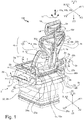
- the design with the upholstery elements is for example in the Figures 1 and 2 clearly visible.
- the holding structure 6 has two holding legs 6a, 6b extending along the height axis Z. These retaining legs 6a, 6b are arranged on the seat part 5 at an outer edge 5a, 5b of the seat part 5 along the width axis Y.
- the holding structure 6 has a cross brace 6c which extends along the width axis Y and connects the holding legs 6a, 6b along the horizontal width axis Y.
- This cross brace 6c can be formed in one piece or in one piece with the holding legs 6a, 6b.
- the retaining legs 6a, 6b can also be connected to the cross brace 6c by means of a screw connection, a rivet connection, a welded connection or some other type of connection.
- the holding structure 6 is thus U-shaped.
- the seat part 5 has a receiving element 23 for the cushion element 22 or the seat surface.
- This receiving element 23 can be manufactured in such a way that it has a corresponding stability which is sufficient for a corresponding introduction of forces through the holding legs 6a, 6b.
- the cross brace 6c could thus be a section of the receiving element 23 which extends along the width direction Y.
- the cross brace 6c could be a single component which is arranged in or on the receiving element 23.
- This cross brace 6c could also be connected to the substructure 32 of the vehicle seat 100 in order to transmit a corresponding force input to it.
- the backrest element 4 comprises a lower part 4a, which is arranged along the height axis Z ′ below the first pivot axis 3, and an upper part 4b, which is arranged along the height axis Z ′ above the first pivot axis 3.
- the upper part 4b is pivoted backwards.
- the lower part 4a is pivoted forward. In this way, lordosis / kyphosis support can be brought about.
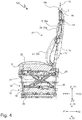
- the base structure 2 is dimensionally stable and extends along the width axis Y '. How out Figure 6 As can be seen, the base structure can have an arch-like structure which extends to the rear, that is to say in the depth direction X'2.
- the basic structure 2 has a central section 25. This middle section 25 is parallel to the first pivot axis 3 and at a distance from the pivot axis along the depth direction X'2.
- the middle section 25 of the base structure 2 can be designed to be reinforced in order to allow a corresponding introduction of force to ensure sufficient stability.
- a lateral section 26a, 26 extends linearly from the middle section 25 towards the pivot axis 3.
- These lateral sections 26a and 26b open at the respective outer edge 2a, 2b of the basic structure into a preferably circular receiving section 27a, 27b.
- a bearing shaft element 17a, 17b is arranged on each of the receiving sections 27a, 27b.
- the pivot axis 3 runs centrally through the bearing shaft elements 17a, 17b.
- the bearing shaft elements 17a, 17b are rotatably mounted in a pivot bearing 7a, 7b of the holding legs 6a, 6b. It would be advantageous if the bearing shaft elements 17a, 17b extend through the retaining legs 6a, 6b along the width axis Y and open into a securing element 28a, 28b. Such a securing element 28a, 28b could, for example, be integrated in an armrest 29a, 29b, for example in Figure 3 indicated. In such an embodiment, the bearing shaft elements 17a, 17b could also serve as a rotary bearing for the armrests 29a, 29b.
- the vehicle seat 100 can also comprise a locking mechanism by means of which the pivoting of the backrest element 4 about the first pivot axis 3 can be locked. Furthermore, the vehicle seat 100 can comprise a reset mechanism by means of which a pivoting of the backrest element 4 about the first pivot axis 3 can be reset to a starting position.
- the backrest element 4 comprises a stability element 8 in the form of a first plate-like element 12.
- the first plate-like element 12 extends along the width direction Y 'and the height direction Z'. It can have a shell shape in which the lower back of the user can be received. For this purpose, the outer edges of the plate-like element would extend forward in the depth direction X'1.
- the first plate-like element 12 is arranged along the height axis Z ′ in a lower region 1c of the central structure 1.
- the first plate-like element 12 extends along the height axis Z 'of the backrest element 4 beyond the pivot axis 3 in the direction of the seat part 5.
- the lower part 4a of the backrest element 4 thus corresponds to the lower section 12a of the first plate-like element 12 protruding beyond the pivot axis 3.
- the upper section 12b of the first plate-like element 12 would accordingly pivot backwards and the lower section Swivel 12a forwards. As already mentioned, this leads to lordosis / kyphosis support.
- the first plate-like element 12 can be arranged pivotably on the central structure and / or be designed to be flexible at least in sections. Thus, a pivoting and / or a deformation of the first plate-like element 12 in the radial direction along the arrow direction 11 about a second pivot axis 10a can be made possible.
- the second pivot axis 10a extends essentially along the height axis Z '. A rotational movement of the user can thus be followed to a certain extent by pivoting or twisting the first plate-like element. Since the lower back is thus further supported, increased seating comfort is made possible.
- a cushion element 20a is also arranged on the first plate-like element 12.
- the first plate-like element 12, or the cushion element. can preferably be designed in such a way that the lower section 12a, or the lower section of the upholstery element 20a arranged thereon, contact the seat part 5 or the upholstery element 22.
- a small free space is provided between the cushion element 22 and the lower section 12a, or the lower section of the cushion element 20a arranged thereon.
- Such a distance is preferably in a range between 0 cm and 7.5 cm, more preferably in a range between 0 cm and 5 cm, more preferably in a range between 0 cm and 2.5 cm.
- the central structure 1, 1a, 1b has at least one support element 1a, 1 which extends along the height axis Z ′ and is connected to the base structure 2 on the underside.
- the Figures 1 to 3 it can be seen that the central structure 1, 1a, 1b has two support elements 1a, 1b which extend along the height axis Z ′ and are connected to the base structure 2 on the underside.
- the support elements 1a, 1b are spaced apart along the width axis Y '.
- the support elements 1a, 1b open into the middle section 25 of the basic structure 2.
- the width of the middle section 25 is predetermined by the spaced-apart support elements 1a, 1b.
- the backrest element 4 has two stability elements 8, which are designed in the form of rib elements 18a, 18b.
- the rib elements 18a, 18b are arranged along the height axis Z 'above the first plate-like element 12 and each extend along the width axis Y'.
- a first rib member 18a extends along it the width direction Y'2 and thus opposite to the second rib element 18b, which extends along the width direction Y'1.
- the rib elements 18a, 18b are P-shaped and also extend slightly forward, that is, in the direction X'1. These rib elements 18a, 18b serve to support the shoulder area of the user.
- the rib elements 18a, 18b can be arranged on the central structure 1, 1a, 1b, which is formed integrally therewith.
- one rib element 18a, 18b is arranged on a support element 1a, 1b or one rib element 18a, 18b is formed integrally with a support element 1a, 1b.
- Conceivable connections between the rib elements 18a, 18b and the support elements 1a, 1b are screw connections, welded connections, riveted connections, etc.
- a rib element 18a, 18b can be formed integrally with a support element 1a, 1b, so the two elements could be formed by a Casting process or similar process are produced.
- a cushion element 20b is also arranged on the rib elements 18a, 18b.
- a headrest part 9 is arranged on the central structure 1.
- the headrest part 9 is arranged along the height axis Z ′ above the rib elements 18a, 18b by means of a first arm element 13.
- the first arm element 13 is arranged between the support elements 1a, 1b along the height axis Z '.
- This can be a fixed arrangement.
- this arrangement can be provided in such a way that the headrest part 9 can be displaced along the arrow 15, that is to say along the height axis Z ′.
- the headrest part 9 is arranged on the central structure 1 by means of a first arm element 13 or an arm.
- the arm element 13 is arranged between the support elements 1a, 1b such that it can be displaced along the height axis Z '.
- a rail device could be provided on the side surfaces 30a, 30b of the support elements 1a, 1b pointing towards the first arm element 13, by means of which the first arm element 13 can be guided.
- a locking mechanism is provided by means of which a certain height of the headrest can be set.
- a reset mechanism is provided by means of which a reset to an initial height is carried out.
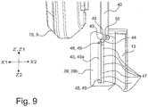
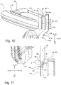
- a guide device 39 is provided on the first arm element 13, in which a second arm element 40 is guided along the height axis Z '.
- a predetermined height position of the second arm element 40 can be fixed by a locking device 41.
- the displacement of the first arm element 13 can take place cumulatively or as an alternative to the displacement of the second arm element 40 relative to the second arm element. It would also be possible for the first arm element 13 to be firmly fixed to the central structure.
- the guide device 39 is U-shaped and has a guide groove 47 or a guide rail in or on each of which a guide pin 42 is guided on the two U-legs 39a, 39b extending along the depth direction X '.
- This embodiment is in the Figures 7 to 12 shown.
- the U-shaped guide device 39 is arranged on an upper section 13c of the first arm element 13. This upper section 13c of the first arm element 13 is arranged offset to the rear (depth direction X'2) along the depth axis X 'with respect to a lower section 13a of the first arm element 13.
- the second arm element 40 essentially assumes the same position along the depth axis X ′ as the lower section 13 a of the first arm element 13.
- the lower section 13a of the first arm element 13 is connected to the upper section 13c via a transition section 13b.
- This transition section 13b and the lower section 13a enclose an angle ⁇ .
- the angle ⁇ is preferably in a range between 10 ° and 80 °, more preferably between 25 ° and 65 °, more preferably between 35 ° and 55 °, more preferably between 40 ° and 50 °, more preferably 45 °.
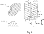
- the locking device 39 also has a predetermined number of projections 43.
- the projections 43 are arranged inwardly in the guide groove 47. Furthermore, the projections 43 are designed to be complementary to a recess 44 of the guide pins 42.
- the locking device 41 furthermore comprises a spring device 45 which has a rail 45a which is pressed in the direction of the projections by means of at least one, preferably several, spring elements 45b.
- the rail 45a extends essentially over the entire length of the guide groove 47.
- the rail 45a is also arranged on the U-leg via two pins 48 which are each guided in a guide 49.
- the maximum displacement path of the rail 45a in the direction of the projections 43 is predetermined by the length of the guide.
- the guide pin 42 is in the lowermost position of the guide groove 47. This corresponds to the lowermost position of the headrest part 9.
- the guide pin 42 is in a locking position in which spring device 45 presses a projection 43 into the recess 44 of the guide pin 42.
- the second arm element 40 and thus also the second plate-like element 19 are held at this specific height position.
- the user can apply a corresponding force along the height axis Z ′ around the height position, as a result of which the press connection between the recess 44 of the guide pin 42 and the projection 43 is released.
- the guide pin 42 can then be displaced to a further projection 43 which lies below or above the original projection 43.
- the respective projection 43 can be received in the recess 44 of the guide pin 42, with the spring device 45 again providing a corresponding press connection between the recess 44 and the now selected projection 43.
- a simple adjustment of the height position of the headrest part 9 is achieved by this configuration.
- a lowermost position of the headrest part can be seen.
- Figure 9 10 and 11 an uppermost position of the headrest part can be seen.
- the guide device 39 has an end receptacle 46 for the one guide pin 42, in which a rotation of the guide pin 42 and the second arm element 40 about a pivot axis S is made possible.
- the end receptacle is arranged along the height axis Z 'at the upper end of the guide groove 47 and is essentially circular.
- the guide pin 42 is located in the end receptacle 46 of the guide groove 47.
- the headrest part 9 is pulled out maximally upwards. Accordingly, the pivot axis S extends along the width axis Y '.
- a locking device 50 which comprises a sheet-like element 51, is also located on the guide device.
- this leaf-like element 51 presses into the exception 44 of the guide pin 42, as a result of which this is locked in the position that is still pivoted forward.
- the sheet-like element 51 can be displaced against the spring force and the guide pin 42 can be displaced into the guide groove 47 again.
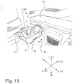
- the vehicle seat 100 can thus be brought into a stowed position in which, on the one hand, the backrest element 4 has been displaced essentially parallel to the seat part 5 or parallel to the depth axis X of the vehicle seat 100.
- This is for example in the Figures 13 , 19th , 20th , 25th and 26th recognizable.
- the headrest part 9 can be pivoted in such a way that it extends essentially parallel to the depth axis X '. In the reference system of the entire vehicle seat 100 that would be Headrest part 9 then extend essentially along the height axis Z '.
- the vehicle seat 100 can be folded up in a very space-saving manner and, if necessary, stowed.
- the vehicle seat 100 can then be moved under a shelf or bed 64 (along arrow 53), for example by means of a guide system 52, and stowed there.
- the advantageously folded vehicle seat takes up extremely little storage space there.
- the headrest part 9 has a second plate-like element 19 on which a cushion element 31 is arranged.
- the second plate-like element 19 is arranged on the first 13 or second arm element 40 by means of a joint element 14.
- This joint element 14 enables the headrest part 9 to pivot about a fourth pivot axis 10c, which runs essentially along the height axis Z ′, and to pivot about a fifth pivot axis 10d, which runs essentially along the width axis Y ′.
- a pivoting about the fourth pivot axis 10c is shown by the double arrow 16b and a pivoting about the fifth pivot axis 10d is shown by the double arrow 16a.
- the joint 14 connects the first 13 or the second arm element 40 with a rib structure 9a, which is V-shaped and on which the second plate-like element 19 is arranged.
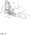
- a locking device 54 for adjusting the inclination of the backrest element 4 relative to the seat part 5 can take place.
- This locking mechanism 54 can be integrated into the holding structure 6 or the holding legs 6a, 6b.
- the locking device 54 comprises a base element 55 which is arranged or fastened to the holding structure 6 or the holding legs 6a, 6b.
- An actuating element 56 is rotatably attached to this base element 55.
- a tooth element 57 is rotatably arranged on the base element 55.
- This tooth element 57 is firmly connected to the central structure 1.
- the tooth element 57 is connected to the basic structure 2.
- the tooth element 57 is mechanically firmly connected to a receiving section 27a, 27b. This can be done, for example, by welding.
- the tooth element 57 has a tooth section 57a in the form of a segment of a circle. Furthermore, a locking element 58 is arranged on the base element 55. This Locking element 58 likewise has a tooth section 58a which can engage in tooth section 57a of tooth element 57. In a locking position, the tooth section 58a engages in the tooth section 57a, whereby the tooth element 57 is fixed. A rotation of the tooth element 57 about an axis of rotation 60 is thus prevented, whereby the inclination of the backrest element 4 relative to the seat part 5 is also fixed.
- the tooth element 57 can then be rotated with the back element, whereby the inclination of the backrest element 4 can be adjusted relative to the seat part.
- the actuating element is displaced against the direction of arrow 61. This can also be done automatically by applying a spring force.
- the locking element 58 can reversibly return to its original position, whereby the tooth section 58a again engages in the tooth section 57a of the tooth element 57, possibly in a different area of the tooth section 57a.
- pivoting and deformation can take place during a rotary movement in three planes, thereby providing optimal support for the user can be done. This can prevent incorrect posture and ensure a high level of seating comfort.
- the pivoting about the first pivot axis 3 provides lordosis / kyphosis support.
- the distance 37 between the first pivot axis 3 can accordingly be selected in such a way that such lordosis / kyphosis support can be generated.
- the first distance between the pivot axis and the seat part is advantageously in a range between 2 cm and 30 cm, more preferably the first distance is in a range between 5 cm and 25 cm. Even more preferably, the first distance is in a range between 5 cm and 15 cm.
- pivot bearing 7a, 7b of the holding legs 6a, 6b were adjustable along the height axis Z. This would allow the distance 37 between the first pivot axis 3 and the seat part 5 to be adjusted, as a result of which the lordosis / kyphosis support could be adapted to the user. This could be done, for example, with a locking device, the bearing shaft elements 17a, 17b being held in locking devices which are arranged at different heights.
- the upholstery element 20a which is arranged on the first plate-like element 12, occupies a certain distance 38 from the first pivot axis 3 through the backrest 21, in conventional seats the backrest cannot be pivoted forward so far that the backrests and the seat part are essentially parallel. Due to the distance 37 according to the invention between the pivot axis 3 and the seat part, or the seat part surface which comes into contact with the user, the backrest 21 or the backrest element 4 can be pivoted so far forward that the central structure or the backrest element essentially are parallel. This allows the seat to take up much smaller storage space.
- the distance 37 should therefore at least correspond to the distance 38.
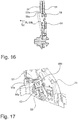
- the seat substructure 32 is shown, which connects the seat part 5 to the vehicle body 33.
- This seat substructure 32 comprises a scissors frame 34 with a suspension device 35, for example an air spring and a damper device 36. Furthermore, horizontal suspension can also be provided.
- the seat substructure 32 can also comprise a cover device 24 which covers the components mentioned
- the vehicle seat 100 is designed as an advantageous passenger seat which is arranged in a utility vehicle cabin 65.
- a utility vehicle cabin can be provided in a truck, for example.
- the vehicle seat 100 is arranged in a front region of the utility vehicle.
- the vehicle seat 100 is in a folded state.
- the backrest element 4 is essentially parallel to the seat part 5. This is made possible by the spacing according to the invention of the first pivot axis 3 along a height axis Z of the vehicle seat 100 being spaced apart from the seat part 5.
- the headrest part 9 can advantageously be folded downwards along the height direction Z2. After the vehicle seat 100 has been folded up, the headrest part 9 would protrude beyond the seat part 5 and would be viewed as a nuisance due to the limited interior space. Due to the advantageous folding down of the headrest part 9, the seat length is considerably reduced in the folded state.
- a bed or shelf 64 is provided behind the vehicle seats 100.
- the advantageous collapsible vehicle seat 100 can according to the embodiments according to FIGS Figures 13 and 19 to 27 can be stowed under the bed or the shelf 64.
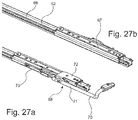
- a guide system 52 or a rail system is provided.
- the vehicle seat 100 is connected to the body floor or the floor of the commercial vehicle cabin by means of this guide system 52.
- at least one, preferably two, lower rail element (s) 66 is / are provided which is / are embedded in the body floor or cabin floor or fastened to it.
- At least one, preferably two, upper rail element (s) 67, which is / are connected to the vehicle seat 100, is / are provided on this lower rail element 66.
- the two lower rail elements 66 advantageously run parallel.
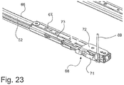
- a locking device 68 is also provided on the upper rail element 67, by means of which the vehicle seat 100 can be locked in a corresponding position.
- a Bowden cable 69 can be provided for operating the locking device 68. This is in the Figures 19 to 23 shown.
- a lever element 70 can be provided ( Figures 24 to 27 ).
- a maximum front position of the upper rail elements 67 is shown, in which the vehicle seat would be in a corresponding maximum front position.
- a maximum rear position of the upper rail elements 67 is shown, in which the vehicle seat in a corresponding maximum rear position. This would be folded up under the bed or under the shelf 64.
- the vehicle seat can only be displaced during the actuation of the locking device 68. As soon as the actuation is released, the locking device 68 engages and locks the vehicle seat 100 in the corresponding position. The shift can be done by muscle strength of the user.
- an actuator could also be provided, which moves the vehicle seat to the desired position. Such an actuator can be driven electrically or hydraulically, for example.
- the locking device 68 is shown.
- This includes a lever element 71 which is rotatable about an axis of rotation.
- the lever element is attached to the upper rail element 67 by means of a fastening element 72.
- Latching elements are provided on the lever element 71, which engage in a toothed strip which is provided on the lower rail element 68.
- a reset element 73 in the form of a spring element is provided, by means of which the rotation of the lever element can be reset. By means of this restoring element 73, after the locking device 68 has been actuated, it is returned to the locked state.
- Folding in the vehicle seat 100 enables a larger area to become free in the front area of the commercial vehicle cabin, either on the passenger side or on the driver's side or in both areas, in order to arrange a table or other desired additional building modules or components here, for example, which are then time-limited Enable use of the commercial vehicle cabin. Another sleeping place can then be arranged in this area, for example.
- the vehicle seat 100 according to the invention with the novel backrest structure 4 is characterized in that struts / strut elements or lateral stability elements 4, which can also be arranged pivotably, to the left and right of a central, force-absorbing longitudinal structure 1 that runs from top to bottom stretch away.
- This centrally arranged rear longitudinal structure 1 is supported on the underside on a pivot axis 3, which is preferably aligned horizontally or based on the horizontal, and is firmly connected to it.
- this rear central structure / longitudinal structure 1 and the pivot axis 3 are suitable for pivoting the backrest 21 forwards and backwards, whereby it is crucial that this pivot axis 3 is raised in relation to the seat part 5 in a U-shaped profile 6, which extends from the seat part 5 in its rear upwards, is arranged.
- said pivot axis 3 is fixed on the left and right in upward-standing U-legs 6a, 6b, a pivoting movement, for example in the area of the lumbar vertebrae or even above or below, can be carried out.
- This tilting movement of the backrest 21 brought about by this causes the backrest part 4a lying below the pivot axis 3 to pivot forwards when pivoted and thereby induce lordosis / kyphosis support.
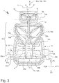
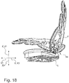
- a vehicle seat 100 is shown in a perspective rear view. It can be seen from this illustration that the vehicle seat 100 is a completely new type of back structure.
- This back structure 4 is composed of a central longitudinal support structure 1a, 1b and, from top to bottom, of individual components 8 or a single component 8.
- the structural elements 1a and 1b which extend from top to bottom and are designed here as preferably vertically extending support elements, are force-absorbing support elements 1a, 1b that are connected to a pivot axis 3 on the underside.
- the entire back structure 4b extending above pivot axis 3 is pivoted forwards or backwards. This applies in the opposite direction to the lower part 4a, which extends towards the seat part 5.
- An upper part 4b and a head part 9 of this backrest 21 are accordingly pivotable with respect to the lower part 4a in the opposite direction with respect to the pivot point 3.
- This pivoting movement is achieved in that the pivot axis 3 is arranged in an elevated position, i.e. higher than the seat part 5.
- This is achieved in that a U-shaped receiving frame 6a, 6b, 6c is arranged in the rear region of the seat part 5 in order to Legs 6a and 6b to achieve an arrangement of the pivot axis 3 in a higher state.
- the backrest structure 4 also has lateral elements 18a and 18b as well as a head part 9, which could also be pivoted about a vertically running pivot axis / force axis 10a, 10b, 10c along the arrow direction 11, but need not.
- the plate-like element 12 is not designed to be inflexible. Rather, this plate-like element 12 has the function that it is flexibly arranged with respect to the pivot axis 3 and possibly the longitudinal support structure 1a, 1b for support purposes of the back and can also twist backwards and forwards in a lateral direction. As a result, the separate part according to the sections 18a and 18b in the upper shoulder area is movable or just not movable according to the plate-like element 12 independently of the area below it.
- the headrest part 9 is arranged on a central arm 13 extending upwards along the force axis 10a, 10b, 10c, which of course also moves forwards or backwards in a joint 14 (not shown here) to the front or to the rear -Tilting of a head can be arranged pivotably.
- This head part 9 can also be arranged so that it can be pivoted laterally to the left and right about a vertical axis.
- pivot axis 3 can be pivoted about the pivot direction 3a, 3b so that the entire backrest structure 4 including the innovatively designed, obliquely upwardly extending and also slightly forwardly extending lateral rib elements 18a, 18b pivot leaves.
- These rib elements 18a, 18b are also formed in a similar shape in the head part 9 as a rib structure 9a.
- the head part can pivot to the left and right according to the double arrow 16b, if this is desired. This is done in Figure 5 shown, which reproduces a plan view of a section of the seat.
- pivot axis 3 is shown with its pivot bracket opposite the U-shaped bearing part, not shown here, extending from bottom to top.
- this area 27a, 27b a pivot or pivot bearing is arranged.
- Both the pivot axis 3 and the rest of the back structure according to the invention preferably have an aluminum alloy for reasons of stability and weight.
- FIG. 1 the seat with the back structure 4 according to the invention and the innovative U-shaped mounting by means of two upwardly extending U-shaped arms 6a, 6b is shown.
- the driver's seat 100 has been developed as a passenger vehicle seat, which can also be designed as a driver's seat, which can be stowed in the folded-down state in the rear area of the commercial vehicle cabin 65 to save space, in order to increase the space requirement in the front area of the commercial vehicle cabin 65, for example for setting up a table to make available to take a meal.
- Such a passenger or driver seat 100 can be changed in such a way that the entire backrest area 4 is to be folded down to the seat part 5, so that a rear side of the backrest area 4 is arranged almost horizontally.
- This vehicle seat 100 can then be displaced backwards in the folded-in state by being displaced backwards on rails or rails 52 placed on the body floor.
- the seat 100 has rail elements 66, 67 or roller elements or sliding blocks or the like of complementary design on its underside in order to enable the vehicle seat 100 to be displaced in the fore and aft direction.
- such a vehicle seat 100 can be locked in the unfolded state, i.e. when it is arranged in the front region of the commercial vehicle cabin 65 in its regular driving state, by means of additional elements not shown here in order to ensure driving safety for the person.
- this vehicle seat 100 can in the folded-in state when it moves backwards into the rear region of the utility vehicle cabin 65 below a bed 64 or the like is arranged, are also locked. This can be made possible, for example, by means of levers and appropriately designed latching elements.
- the pivot axis 3, about which the backrest part 4 is folded down onto the seat part 5, is arranged in an elevated position.
- This means that the pivot axis 3 in the present case is held with bearing legs 6a, 6b extending upward on the left and right side, so that the pivot axis 3 is at a distance from the seat part 5 in the vertical direction Z.
- the cushion elements 20 of the backrest part 4 and cushion elements 22 of the seat part 5 find sufficient space when the backrest part 4 is folded down. This enables the backrest part 4 to really be in the horizontal direction and the upholstery elements 20, 22 not obstructing each other when the backrest part 4 is folded down or when the backrest part is pivoted down.
- the pivot axis 3 is arranged running in the horizontal direction behind the backrest part 4 and at the same time holds the entire backrest part 4.
- the backrest part 4 is arranged separately from the seat part. This is also clearly shown in the figures, which also show a central structure 4, which is characterized by the fact that it extends upwards from the pivot axis 3 in the lower area and is therefore easy to handle due to a centrally arranged central structure with structural elements extending laterally therefrom and space-saving backrest structure.
- the shoulder area and the backrest area underneath are formed separately with shell elements.
- the backrest element 4 is preferably made of aluminum or an aluminum alloy in order to obtain a correspondingly low weight.
- the already mentioned upwardly extending laterally arranged legs 6a, 6b have bearing elements on their upper side, for example in the form of ball bearings, in order to be able to mount the pivot axis 3 or the base structure 2 at the ends therein.
- the upwardly extending legs 6a, 6b are optionally provided with armrests 13. These can also be pivoted.
- the upwardly extending leg elements 6a, 6b can also be connected in a U-shape as a one-piece element together with parts of the seat part 5 or a seat plate.
- Fig. 28 the vehicle seat 100 is shown from above.
- the backrest 4 which has the structural elements in the rear region of the backrest 4, can be clearly seen.
- the pivot axis 3, which is mounted in the upwardly extending leg elements 6a, 6b, is also shown.
- the seat part 5 can also be seen.
Landscapes
- Engineering & Computer Science (AREA)
- Aviation & Aerospace Engineering (AREA)
- Transportation (AREA)
- Mechanical Engineering (AREA)
- Seats For Vehicles (AREA)
Claims (14)
- Siège de véhicule (100) ayant une étendue le long d'un axe dans le sens de la hauteur Z et d'un axe dans le sens de la largeur Y, comportant une partie assise (5) et un élément dossier (4), lequel s'étend le long d'un axe dans le sens de la hauteur Z' et d'un axe dans le sens de la largeur Y', dans lequel l'élément dossier (4) présente une structure centrale (1, 1a, 1b) s'étendant le long de l'axe dans le sens de la hauteur Z', laquelle est disposée de façon centrale le long de l'axe dans le sens de la largeur Y' et débouche dans une structure de base (2) s'étendant sensiblement le long de l'axe dans le sens de la largeur Y', dans lequel l'élément dossier (4) présente au moins un élément de stabilité (8), lequel s'étend à partir de la structure centrale (1, 1a, 1b) le long de l'axe dans le sens de la largeur Y', dans lequel la structure de base (2) est disposée apte à pivoter dans une structure de maintien (6) du siège de véhicule (100), de telle sorte que l'élément dossier (4) est apte à pivoter autour d'un premier axe de pivotement (3),
caractérisé par le fait que
le premier axe de pivotement (3) est espacé de la partie assise (5) le long d'un axe dans le sens de la hauteur Z du siège du véhicule, l'élément dossier (4) comportant une partie inférieure (4a), laquelle est disposée au-dessous du premier axe de pivotement (3) le long de l'axe dans le sens de la hauteur Z', et une partie supérieure (4b), laquelle est disposée au-dessus du premier axe de pivotement (3) le long de l'axe dans le sens de la hauteur Z'. - Siège de véhicule (100) selon la revendication 1,
caractérisé par le fait que
la structure de maintien (6) présente deux branches de maintien (6a, 6b) s'étendant le long de l'axe dans le sens de la hauteur Z, les branches de maintien (6a, 6b) étant disposés sur la partie assise (5) sur respectivement un bord externe (5a, 5b) de la partie assise (5) le long de l'axe dans le sens de la largeur Y, la structure de maintien (6) étant réalisée en forme de U, la structure de maintien (6) présentant une traverse (6c) s'étendant le long de l'axe dans le sens de la largeur Y, laquelle relie les branches de maintien (6a, 6b). - Siège de véhicule (100) selon l'une des revendications précédentes,
caractérisé par le fait que
la structure de base (2) est réalisée dimensionnellement stable, la structure de base (2) présentant, sur ses bords externes (2a, 2b) le long de l'axe dans le sens de la largeur Y', un élément arbre de palier (17a, 17b), lequel est disposé dans un palier pivotant (7a, 7b) d'une branche de maintien (6a, 6b). - Siège de véhicule (100) selon l'une des revendications précédentes,
caractérisé par le fait que
le siège de véhicule (100) comporte un mécanisme de verrouillage au moyen duquel le pivotement de l'élément dossier (4) autour du premier axe de pivotement (3) est verrouillable. - Siège de véhicule (100) selon l'une des revendications précédentes,
caractérisé par le fait que
le siège de véhicule (100) comporte un mécanisme de rappel au moyen duquel un pivotement de l'élément dossier (4) autour du premier axe de pivotement (3) est apte à être rappelé à une position initiale. - Siège de véhicule (100) selon l'une des revendications précédentes,
caractérisé par le fait que
l'élément dossier (4) comporte un élément de stabilité (8) sous forme d'un premier élément en forme de plaque (12), le premier élément en forme de plaque (12) étant disposé dans une région inférieure (1c) de la structure centrale (1) le long de l'axe dans le sens de la hauteur Z', le premier élément en forme de plaque (12) s'étendant au-delà de l'axe de pivotement (3) en direction de la partie assise (5) le long de l'axe dans le sens de la hauteur Z' de l'élément dossier (4), la partie inférieure (4) de l'élément dossier (4) étant la section inférieure (12a) du premier élément en forme de plaque (12) en saillie au-delà de l'axe de pivotement (3). - Siège de véhicule (100) la revendication 6,
caractérisé par le fait que
le premier élément en forme de plaque (12) est disposé apte à pivoter sur la structure centrale et/ou est réalisé flexible au moins par sections, un pivotement et/ou une déformation du premier élément en forme de plaque (12) étant possible autour d'un second axe de pivotement (10a) dans la direction radiale, le second axe de pivotement (10a) s'étendant sensiblement le long de l'axe dans le sens de la hauteur Z'. - Siège de véhicule (100) selon l'une des revendications précédentes,
caractérisé par le fait que
la structure centrale (1, 1a, 1b) présente au moins un élément d'appui (1, 1a, 1b) s'étendant le long de l'axe dans le sens de la hauteur Z', qui est relié côté inférieur avec la structure de base (2), la structure centrale (1, 1a, 1b) présentant deux éléments d'appui (1a, 1b) s'étendant le long de l'axe dans le sens de la hauteur Z', qui sont reliés côté inférieur avec la structure de base (2), les éléments d'appui (1a, 1b) étant espacés le long de l'axe dans le sens de la largeur Y'. - Siège de véhicule (100) selon l'une des revendications précédentes,
caractérisé par le fait que
l'élément dossier (4) présente deux éléments de stabilité (8), qui sont réalisés sous forme d'éléments ailettes (18a, 18b), les éléments ailettes (18a, 18b) étant disposés au-dessus du premier élément en forme de plaque (12) le long de l'axe dans le sens de la hauteur Z, les éléments ailettes (1, 1a, 1b) présentant chacun une étendue le long de l'axe dans le sens de la largeur Y', un premier élément ailette (18a) s'étendant en direction opposée par rapport au second élément ailette (18b), les éléments ailettes (18a, 18b) étant disposés sur la structure centrale (1, 1a, 1b) ou étant formés d'un seul tenant avec celle-ci, chaque élément ailette (18a, 18b) étant disposé sur un élément d'appui (1a, 1b) ou chaque élément ailette (18b) étant formé d'un seul tenant avec un élément d'appui (1a, 1b). - Siège de véhicule (100) selon l'une des revendications précédentes,
caractérisé par le fait qu'
une partie appui-tête (9) est disposée sur la structure centrale (1), la partie appui-tête (9) étant disposée au-dessus des éléments ailettes (18a, 18b) le long de l'axe dans le sens de la hauteur Z', la partie appui-tête (9) étant déplacable le long de l'axe dans le sens de la hauteur Z', la partie appui-tête (9) étant disposée sur la structure centrale (1) au moyen d'un premier élément bras (13), l'élément bras (13) étant disposé déplaçable le long de l'axe dans le sens de la hauteur Z' entre les éléments d'appui (1a, 1b). - Siège de véhicule (100) selon la revendication 10,
caractérisé par le fait que
la partie appui-tête (9) est déplaçable le long de l'axe dans le sens de la hauteur Z', un dispositif de guidage (39) étant prévu sur le premier élément bras (13), dispositif dans lequel un second élément bras (40) est guidé le long de l'axe dans le sens de la hauteur Z', une position en hauteur prédéfinie du second élément bras (40) étant apte à être fixée par un dispositif de blocage (41), un second élément en forme de plaque (19) étant disposé sur le second élément bras (40). - Siège de véhicule (100) selon l'une des revendications 10 ou 11,
caractérisé par le fait qu'
au moins une broche de guidage (42) est prévue sur le second élément bras (40), la broche de guidage (42) étant guidée dans le dispositif de guidage (41), le dispositif de blocage (41) présentant un nombre prédéfini de saillies (43), lesquelles sont réalisées de façon complémentaire à un renfoncement (44) prévu sur la broche de guidage (42), où, dans une position de blocage, un dispositif à ressort (45) presse une saillie (43) dans le renfoncement (44) de la broche de guidage (42), le dispositif de guidage (39) comportant un logement d'extrémité (46) pour ladite au moins une broche de guidage (42), dans lequel une rotation de la broche de guidage (42) et du second élément bras (40) autour d'un axe de pivotement S est rendue possible, l'axe de pivotement S s'étendant le long de l'axe dans le sens de la largeur Y', le second élément en forme de plaque (19) étant apte à pivoter vers l'avant le long de l'axe dans le sens de la profondeur X' par le pivotement du second élément bras (40). - Siège de véhicule (100) selon l'une des revendications 10 à 12,
caractérisé par le fait que
la partie appui-tête (9) présente un second élément en forme de plaque (19), le second élément en forme de plaque (19) étant disposé sur le premier (13) ou le second (40) élément bras au moyen d'un élément d'articulation (14), le second élément en forme de plaque (19) étant apte à pivoter autour d'un quatrième axe de pivotement (10c), lequel s'étend sensiblement le long de l'axe dans le sens de la hauteur Z', le second élément en forme de plaque (19) étant apte à pivoter autour d'un cinquième axe de pivotement (10d), lequel s'étend sensiblement le long de l'axe dans le sens de la largeur Y'. - Cabine de véhicule utilitaire (65) comportant un siège de véhicule (100) selon l'une des revendications préédentes 1 à 14, le siège de véhicule (100) étant disposé dans la cabine de véhicule utilitaire (65) déplaçable au moyen d'un système de guidage (52).
Applications Claiming Priority (2)
| Application Number | Priority Date | Filing Date | Title |
|---|---|---|---|
| DE102018122959 | 2018-09-19 | ||
| DE102019122542.6A DE102019122542B4 (de) | 2018-09-19 | 2019-08-21 | Fahrzeugsitz und Nutzfahrzeugkabine mit Fahrzeugsitz |
Publications (2)
| Publication Number | Publication Date |
|---|---|
| EP3626523A1 EP3626523A1 (fr) | 2020-03-25 |
| EP3626523B1 true EP3626523B1 (fr) | 2021-01-06 |
Family
ID=67956537
Family Applications (1)
| Application Number | Title | Priority Date | Filing Date |
|---|---|---|---|
| EP19197240.5A Active EP3626523B1 (fr) | 2018-09-19 | 2019-09-13 | Siège de véhicule pour cabines des véhicules utilitaires |
Country Status (2)
| Country | Link |
|---|---|
| EP (1) | EP3626523B1 (fr) |
| CN (1) | CN110920475B (fr) |
Cited By (1)
| Publication number | Priority date | Publication date | Assignee | Title |
|---|---|---|---|---|
| FR3140029A1 (fr) | 2022-09-23 | 2024-03-29 | Psa Automobiles Sa | Siège avec airbag pour véhicule automobile |
Families Citing this family (4)
| Publication number | Priority date | Publication date | Assignee | Title |
|---|---|---|---|---|
| CA3124181C (fr) | 2020-07-08 | 2023-09-19 | Oshkosh Corporation | Assemblage de serrure de porte pour vehicule de livraison |
| DE102020134186B3 (de) * | 2020-12-18 | 2022-03-24 | Grammer Aktiengesellschaft | Fahrzeugsitz mit einer Rückenlehne |
| DE102020134209B3 (de) * | 2020-12-18 | 2022-02-10 | Grammer Aktiengesellschaft | Fahrzeugsitz mit einer Rückenlehne |
| DE102022206084B4 (de) * | 2022-06-16 | 2025-03-06 | Adient Us Llc | Rückenlehne eines Fahrzeugsitzes sowie ein Verfahren zur Montage |
Family Cites Families (11)
| Publication number | Priority date | Publication date | Assignee | Title |
|---|---|---|---|---|
| FR2791616B1 (fr) * | 1999-04-02 | 2001-06-29 | Matra Automobile | Siege escamotable par repli pour passager de vehicule |
| CN100473563C (zh) * | 2005-06-29 | 2009-04-01 | 格拉默股份公司 | 汽车座椅 |
| DE102009019348B4 (de) * | 2009-05-01 | 2026-02-12 | Brose Fahrzeugteile SE & Co. Kommanditgesellschaft, Coburg | Vordersitz eines Kraftfahrzeugs |
| DE102009033883A1 (de) * | 2009-07-20 | 2011-01-27 | Bayerische Motoren Werke Aktiengesellschaft | Fahrzeugsitz mit einer Rückenlehne, die eine stützende Strebenstruktur aufweist |
| DE102011113789B4 (de) * | 2011-08-29 | 2014-04-24 | Keiper Gmbh & Co. Kg | Fahrzeugsitz, insbesondere Kraftfahrzeugsitz |
| DE102012018351A1 (de) * | 2012-09-17 | 2014-03-20 | Isringhausen Gmbh & Co. Kg | Fahrzeugsitz sowie Verfahren zum Verbringen eines Fahrzeugsitzes |
| JP5598557B2 (ja) * | 2013-01-10 | 2014-10-01 | トヨタ自動車株式会社 | 車両用シート装置 |
| US9480340B1 (en) * | 2013-09-17 | 2016-11-01 | Corecentric LLC | Systems and methods for providing ergonomic exercise chairs |
| JP6192221B2 (ja) * | 2013-11-18 | 2017-09-06 | 株式会社タチエス | シート |
| CN204821206U (zh) * | 2015-05-27 | 2015-12-02 | 江苏公爵新能源汽车有限公司 | 一种新型汽车座椅 |
| CN107125990A (zh) * | 2017-04-26 | 2017-09-05 | 广东顺德奥格斯格家具有限公司 | 一种办公椅 |
-
2019
- 2019-09-13 EP EP19197240.5A patent/EP3626523B1/fr active Active
- 2019-09-19 CN CN201910884572.3A patent/CN110920475B/zh active Active
Non-Patent Citations (1)
| Title |
|---|
| None * |
Cited By (1)
| Publication number | Priority date | Publication date | Assignee | Title |
|---|---|---|---|---|
| FR3140029A1 (fr) | 2022-09-23 | 2024-03-29 | Psa Automobiles Sa | Siège avec airbag pour véhicule automobile |
Also Published As
| Publication number | Publication date |
|---|---|
| CN110920475B (zh) | 2022-04-12 |
| EP3626523A1 (fr) | 2020-03-25 |
| CN110920475A (zh) | 2020-03-27 |
Similar Documents
| Publication | Publication Date | Title |
|---|---|---|
| EP3626523B1 (fr) | Siège de véhicule pour cabines des véhicules utilitaires | |
| DE102019122542B4 (de) | Fahrzeugsitz und Nutzfahrzeugkabine mit Fahrzeugsitz | |
| EP1817198B1 (fr) | Siege de vehicule, notamment siege de vehicule automobile | |
| EP1911371B1 (fr) | Meuble d'assise, en particulier chaise de bureau | |
| DE112016000476B4 (de) | Fahrzeugsitz | |
| EP1488950B1 (fr) | Siège de véhicule, en particulier siège d'automobile | |
| EP1743612B1 (fr) | Fauteuil roulant pour handicapés | |
| EP2403761B1 (fr) | Siège de passager d'avion | |
| DE68916739T2 (de) | Sitzaufbau für ein Fahrzeug. | |
| EP1848609B1 (fr) | Siege de vehicule a moteur | |
| DE19830418B4 (de) | Stuhlanordnung | |
| DE19620872A1 (de) | Fahrzeugsitz mit in Höhe und Länge verstellbarer Sitzfläche | |
| DE10012590B4 (de) | Vor einem Laderaum eines Kraftfahrzeuges angeordnete Sitzanordnung | |
| WO2012152553A1 (fr) | Siège de véhicule, en particulier siège de véhicule automobile | |
| EP1836070B1 (fr) | Siege de vehicule | |
| DE102005032382B4 (de) | Fahrzeugsitz, insbesondere Kraftfahrzeugsitz | |
| EP0943483A2 (fr) | Agencement d'au moins deux sièges adjacents | |
| EP1974633A2 (fr) | Meubles destinés à s'asseoir | |
| EP4323235B1 (fr) | Support de jambes pour un siège de véhicule, siège de véhicule d'un véhicule automobile et véhicule automobile | |
| DE2019742A1 (de) | Sitz fuer Kraftfahrzeuge | |
| EP1627768B1 (fr) | Siège pliable en particulier pour véhicules automobiles | |
| WO2008034606A1 (fr) | Accoudoir pour un siège de véhicule ainsi que siège de véhicule comportant un accoudoir | |
| EP3626522B1 (fr) | Construction de dossier pour un siège de véhicule | |
| DE102005031252B4 (de) | Rückenlehneneinheit eines Kraftfahrzeugsitzes | |
| EP2708406B1 (fr) | Siège doté d'un dispositif de blocage |
Legal Events
| Date | Code | Title | Description |
|---|---|---|---|
| PUAI | Public reference made under article 153(3) epc to a published international application that has entered the european phase |
Free format text: ORIGINAL CODE: 0009012 |
|
| STAA | Information on the status of an ep patent application or granted ep patent |
Free format text: STATUS: THE APPLICATION HAS BEEN PUBLISHED |
|
| AK | Designated contracting states |
Kind code of ref document: A1 Designated state(s): AL AT BE BG CH CY CZ DE DK EE ES FI FR GB GR HR HU IE IS IT LI LT LU LV MC MK MT NL NO PL PT RO RS SE SI SK SM TR |
|
| AX | Request for extension of the european patent |
Extension state: BA ME |
|
| STAA | Information on the status of an ep patent application or granted ep patent |
Free format text: STATUS: REQUEST FOR EXAMINATION WAS MADE |
|
| 17P | Request for examination filed |
Effective date: 20200724 |
|
| RBV | Designated contracting states (corrected) |
Designated state(s): AL AT BE BG CH CY CZ DE DK EE ES FI FR GB GR HR HU IE IS IT LI LT LU LV MC MK MT NL NO PL PT RO RS SE SI SK SM TR |
|
| GRAP | Despatch of communication of intention to grant a patent |
Free format text: ORIGINAL CODE: EPIDOSNIGR1 |
|
| STAA | Information on the status of an ep patent application or granted ep patent |
Free format text: STATUS: GRANT OF PATENT IS INTENDED |
|
| RAP1 | Party data changed (applicant data changed or rights of an application transferred) |
Owner name: GRAMMER AG |
|
| RIC1 | Information provided on ipc code assigned before grant |
Ipc: B60N 2/856 20180101ALI20200911BHEP Ipc: B60N 2/64 20060101AFI20200911BHEP Ipc: B60N 2/821 20180101ALI20200911BHEP Ipc: B60N 2/68 20060101ALI20200911BHEP Ipc: B60N 2/20 20060101ALI20200911BHEP Ipc: B60N 2/06 20060101ALI20200911BHEP Ipc: B60N 2/30 20060101ALI20200911BHEP Ipc: B60N 2/02 20060101ALI20200911BHEP Ipc: B60N 2/832 20180101ALI20200911BHEP |
|
| INTG | Intention to grant announced |
Effective date: 20201013 |
|
| RIN1 | Information on inventor provided before grant (corrected) |
Inventor name: OTT, RICHARD Inventor name: FISCHER, JOHANN Inventor name: HEGEN, MARTIN |
|
| GRAS | Grant fee paid |
Free format text: ORIGINAL CODE: EPIDOSNIGR3 |
|
| GRAA | (expected) grant |
Free format text: ORIGINAL CODE: 0009210 |
|
| STAA | Information on the status of an ep patent application or granted ep patent |
Free format text: STATUS: THE PATENT HAS BEEN GRANTED |
|
| AK | Designated contracting states |
Kind code of ref document: B1 Designated state(s): AL AT BE BG CH CY CZ DE DK EE ES FI FR GB GR HR HU IE IS IT LI LT LU LV MC MK MT NL NO PL PT RO RS SE SI SK SM TR |
|
| REG | Reference to a national code |
Ref country code: GB Ref legal event code: FG4D Free format text: NOT ENGLISH |
|
| REG | Reference to a national code |
Ref country code: AT Ref legal event code: REF Ref document number: 1351998 Country of ref document: AT Kind code of ref document: T Effective date: 20210115 Ref country code: CH Ref legal event code: EP |
|
| REG | Reference to a national code |
Ref country code: DE Ref legal event code: R096 Ref document number: 502019000647 Country of ref document: DE |
|
| REG | Reference to a national code |
Ref country code: IE Ref legal event code: FG4D Free format text: LANGUAGE OF EP DOCUMENT: GERMAN |
|
| REG | Reference to a national code |
Ref country code: SE Ref legal event code: TRGR |
|
| REG | Reference to a national code |
Ref country code: NL Ref legal event code: MP Effective date: 20210106 |
|
| REG | Reference to a national code |
Ref country code: LT Ref legal event code: MG9D |
|
| PG25 | Lapsed in a contracting state [announced via postgrant information from national office to epo] |
Ref country code: BG Free format text: LAPSE BECAUSE OF FAILURE TO SUBMIT A TRANSLATION OF THE DESCRIPTION OR TO PAY THE FEE WITHIN THE PRESCRIBED TIME-LIMIT Effective date: 20210406 Ref country code: HR Free format text: LAPSE BECAUSE OF FAILURE TO SUBMIT A TRANSLATION OF THE DESCRIPTION OR TO PAY THE FEE WITHIN THE PRESCRIBED TIME-LIMIT Effective date: 20210106 Ref country code: FI Free format text: LAPSE BECAUSE OF FAILURE TO SUBMIT A TRANSLATION OF THE DESCRIPTION OR TO PAY THE FEE WITHIN THE PRESCRIBED TIME-LIMIT Effective date: 20210106 Ref country code: GR Free format text: LAPSE BECAUSE OF FAILURE TO SUBMIT A TRANSLATION OF THE DESCRIPTION OR TO PAY THE FEE WITHIN THE PRESCRIBED TIME-LIMIT Effective date: 20210407 Ref country code: PT Free format text: LAPSE BECAUSE OF FAILURE TO SUBMIT A TRANSLATION OF THE DESCRIPTION OR TO PAY THE FEE WITHIN THE PRESCRIBED TIME-LIMIT Effective date: 20210506 Ref country code: NO Free format text: LAPSE BECAUSE OF FAILURE TO SUBMIT A TRANSLATION OF THE DESCRIPTION OR TO PAY THE FEE WITHIN THE PRESCRIBED TIME-LIMIT Effective date: 20210406 Ref country code: LT Free format text: LAPSE BECAUSE OF FAILURE TO SUBMIT A TRANSLATION OF THE DESCRIPTION OR TO PAY THE FEE WITHIN THE PRESCRIBED TIME-LIMIT Effective date: 20210106 |
|
| PG25 | Lapsed in a contracting state [announced via postgrant information from national office to epo] |
Ref country code: LV Free format text: LAPSE BECAUSE OF FAILURE TO SUBMIT A TRANSLATION OF THE DESCRIPTION OR TO PAY THE FEE WITHIN THE PRESCRIBED TIME-LIMIT Effective date: 20210106 Ref country code: PL Free format text: LAPSE BECAUSE OF FAILURE TO SUBMIT A TRANSLATION OF THE DESCRIPTION OR TO PAY THE FEE WITHIN THE PRESCRIBED TIME-LIMIT Effective date: 20210106 Ref country code: RS Free format text: LAPSE BECAUSE OF FAILURE TO SUBMIT A TRANSLATION OF THE DESCRIPTION OR TO PAY THE FEE WITHIN THE PRESCRIBED TIME-LIMIT Effective date: 20210106 |
|
| PG25 | Lapsed in a contracting state [announced via postgrant information from national office to epo] |
Ref country code: IS Free format text: LAPSE BECAUSE OF FAILURE TO SUBMIT A TRANSLATION OF THE DESCRIPTION OR TO PAY THE FEE WITHIN THE PRESCRIBED TIME-LIMIT Effective date: 20210506 |
|
| REG | Reference to a national code |
Ref country code: DE Ref legal event code: R097 Ref document number: 502019000647 Country of ref document: DE |
|
| PG25 | Lapsed in a contracting state [announced via postgrant information from national office to epo] |
Ref country code: SM Free format text: LAPSE BECAUSE OF FAILURE TO SUBMIT A TRANSLATION OF THE DESCRIPTION OR TO PAY THE FEE WITHIN THE PRESCRIBED TIME-LIMIT Effective date: 20210106 Ref country code: CZ Free format text: LAPSE BECAUSE OF FAILURE TO SUBMIT A TRANSLATION OF THE DESCRIPTION OR TO PAY THE FEE WITHIN THE PRESCRIBED TIME-LIMIT Effective date: 20210106 Ref country code: EE Free format text: LAPSE BECAUSE OF FAILURE TO SUBMIT A TRANSLATION OF THE DESCRIPTION OR TO PAY THE FEE WITHIN THE PRESCRIBED TIME-LIMIT Effective date: 20210106 |
|
| PLBE | No opposition filed within time limit |
Free format text: ORIGINAL CODE: 0009261 |
|
| STAA | Information on the status of an ep patent application or granted ep patent |
Free format text: STATUS: NO OPPOSITION FILED WITHIN TIME LIMIT |
|
| PG25 | Lapsed in a contracting state [announced via postgrant information from national office to epo] |
Ref country code: DK Free format text: LAPSE BECAUSE OF FAILURE TO SUBMIT A TRANSLATION OF THE DESCRIPTION OR TO PAY THE FEE WITHIN THE PRESCRIBED TIME-LIMIT Effective date: 20210106 Ref country code: SK Free format text: LAPSE BECAUSE OF FAILURE TO SUBMIT A TRANSLATION OF THE DESCRIPTION OR TO PAY THE FEE WITHIN THE PRESCRIBED TIME-LIMIT Effective date: 20210106 Ref country code: RO Free format text: LAPSE BECAUSE OF FAILURE TO SUBMIT A TRANSLATION OF THE DESCRIPTION OR TO PAY THE FEE WITHIN THE PRESCRIBED TIME-LIMIT Effective date: 20210106 |
|
| 26N | No opposition filed |
Effective date: 20211007 |
|
| PG25 | Lapsed in a contracting state [announced via postgrant information from national office to epo] |
Ref country code: ES Free format text: LAPSE BECAUSE OF FAILURE TO SUBMIT A TRANSLATION OF THE DESCRIPTION OR TO PAY THE FEE WITHIN THE PRESCRIBED TIME-LIMIT Effective date: 20210106 Ref country code: AL Free format text: LAPSE BECAUSE OF FAILURE TO SUBMIT A TRANSLATION OF THE DESCRIPTION OR TO PAY THE FEE WITHIN THE PRESCRIBED TIME-LIMIT Effective date: 20210106 |
|
| PG25 | Lapsed in a contracting state [announced via postgrant information from national office to epo] |
Ref country code: SI Free format text: LAPSE BECAUSE OF FAILURE TO SUBMIT A TRANSLATION OF THE DESCRIPTION OR TO PAY THE FEE WITHIN THE PRESCRIBED TIME-LIMIT Effective date: 20210106 |
|
| REG | Reference to a national code |
Ref country code: BE Ref legal event code: MM Effective date: 20210930 |
|
| PG25 | Lapsed in a contracting state [announced via postgrant information from national office to epo] |
Ref country code: IS Free format text: LAPSE BECAUSE OF FAILURE TO SUBMIT A TRANSLATION OF THE DESCRIPTION OR TO PAY THE FEE WITHIN THE PRESCRIBED TIME-LIMIT Effective date: 20210506 Ref country code: MC Free format text: LAPSE BECAUSE OF FAILURE TO SUBMIT A TRANSLATION OF THE DESCRIPTION OR TO PAY THE FEE WITHIN THE PRESCRIBED TIME-LIMIT Effective date: 20210106 |
|
| PG25 | Lapsed in a contracting state [announced via postgrant information from national office to epo] |
Ref country code: LU Free format text: LAPSE BECAUSE OF NON-PAYMENT OF DUE FEES Effective date: 20210913 Ref country code: IE Free format text: LAPSE BECAUSE OF NON-PAYMENT OF DUE FEES Effective date: 20210913 Ref country code: BE Free format text: LAPSE BECAUSE OF NON-PAYMENT OF DUE FEES Effective date: 20210930 |
|
| REG | Reference to a national code |
Ref country code: CH Ref legal event code: PL |
|
| PG25 | Lapsed in a contracting state [announced via postgrant information from national office to epo] |
Ref country code: NL Free format text: LAPSE BECAUSE OF NON-PAYMENT OF DUE FEES Effective date: 20210206 Ref country code: CY Free format text: LAPSE BECAUSE OF FAILURE TO SUBMIT A TRANSLATION OF THE DESCRIPTION OR TO PAY THE FEE WITHIN THE PRESCRIBED TIME-LIMIT Effective date: 20210106 |
|
| PG25 | Lapsed in a contracting state [announced via postgrant information from national office to epo] |
Ref country code: LI Free format text: LAPSE BECAUSE OF NON-PAYMENT OF DUE FEES Effective date: 20220930 Ref country code: HU Free format text: LAPSE BECAUSE OF FAILURE TO SUBMIT A TRANSLATION OF THE DESCRIPTION OR TO PAY THE FEE WITHIN THE PRESCRIBED TIME-LIMIT; INVALID AB INITIO Effective date: 20190913 Ref country code: CH Free format text: LAPSE BECAUSE OF NON-PAYMENT OF DUE FEES Effective date: 20220930 |
|
| PG25 | Lapsed in a contracting state [announced via postgrant information from national office to epo] |
Ref country code: MK Free format text: LAPSE BECAUSE OF FAILURE TO SUBMIT A TRANSLATION OF THE DESCRIPTION OR TO PAY THE FEE WITHIN THE PRESCRIBED TIME-LIMIT Effective date: 20210106 |
|
| PG25 | Lapsed in a contracting state [announced via postgrant information from national office to epo] |
Ref country code: MT Free format text: LAPSE BECAUSE OF FAILURE TO SUBMIT A TRANSLATION OF THE DESCRIPTION OR TO PAY THE FEE WITHIN THE PRESCRIBED TIME-LIMIT Effective date: 20210106 |
|
| PGFP | Annual fee paid to national office [announced via postgrant information from national office to epo] |
Ref country code: DE Payment date: 20250919 Year of fee payment: 7 |
|
| PGFP | Annual fee paid to national office [announced via postgrant information from national office to epo] |
Ref country code: TR Payment date: 20250909 Year of fee payment: 7 |
|
| PGFP | Annual fee paid to national office [announced via postgrant information from national office to epo] |
Ref country code: GB Payment date: 20250923 Year of fee payment: 7 |
|
| PGFP | Annual fee paid to national office [announced via postgrant information from national office to epo] |
Ref country code: FR Payment date: 20250926 Year of fee payment: 7 |
|
| PGFP | Annual fee paid to national office [announced via postgrant information from national office to epo] |
Ref country code: SE Payment date: 20250922 Year of fee payment: 7 |
|
| REG | Reference to a national code |
Ref country code: AT Ref legal event code: MM01 Ref document number: 1351998 Country of ref document: AT Kind code of ref document: T Effective date: 20240913 |
|
| PG25 | Lapsed in a contracting state [announced via postgrant information from national office to epo] |
Ref country code: AT Free format text: LAPSE BECAUSE OF NON-PAYMENT OF DUE FEES Effective date: 20240913 |
|
| PGFP | Annual fee paid to national office [announced via postgrant information from national office to epo] |
Ref country code: IT Payment date: 20250930 Year of fee payment: 7 |
|
| PGFP | Annual fee paid to national office [announced via postgrant information from national office to epo] |
Ref country code: AT Payment date: 20260410 Year of fee payment: 5 |