EP4323235B1 - Support de jambes pour un siège de véhicule, siège de véhicule d'un véhicule automobile et véhicule automobile - Google Patents
Support de jambes pour un siège de véhicule, siège de véhicule d'un véhicule automobile et véhicule automobile Download PDFInfo
- Publication number
- EP4323235B1 EP4323235B1 EP22716364.9A EP22716364A EP4323235B1 EP 4323235 B1 EP4323235 B1 EP 4323235B1 EP 22716364 A EP22716364 A EP 22716364A EP 4323235 B1 EP4323235 B1 EP 4323235B1
- Authority
- EP
- European Patent Office
- Prior art keywords
- support
- lower leg
- use position
- vehicle seat
- vehicle
- Prior art date
- Legal status (The legal status is an assumption and is not a legal conclusion. Google has not performed a legal analysis and makes no representation as to the accuracy of the status listed.)
- Active
Links
Images



Classifications
-
- B—PERFORMING OPERATIONS; TRANSPORTING
- B60—VEHICLES IN GENERAL
- B60N—SEATS SPECIALLY ADAPTED FOR VEHICLES; VEHICLE PASSENGER ACCOMMODATION NOT OTHERWISE PROVIDED FOR
- B60N2/00—Seats specially adapted for vehicles; Arrangement or mounting of seats in vehicles
- B60N2/90—Details or parts not otherwise provided for
- B60N2/995—Lower-leg-rests, e.g. calf-rests
-
- B—PERFORMING OPERATIONS; TRANSPORTING
- B60—VEHICLES IN GENERAL
- B60N—SEATS SPECIALLY ADAPTED FOR VEHICLES; VEHICLE PASSENGER ACCOMMODATION NOT OTHERWISE PROVIDED FOR
- B60N3/00—Arrangements or adaptations of other passenger fittings, not otherwise provided for
- B60N3/001—Arrangements or adaptations of other passenger fittings, not otherwise provided for of tables or trays
-
- B—PERFORMING OPERATIONS; TRANSPORTING
- B60—VEHICLES IN GENERAL
- B60N—SEATS SPECIALLY ADAPTED FOR VEHICLES; VEHICLE PASSENGER ACCOMMODATION NOT OTHERWISE PROVIDED FOR
- B60N3/00—Arrangements or adaptations of other passenger fittings, not otherwise provided for
- B60N3/001—Arrangements or adaptations of other passenger fittings, not otherwise provided for of tables or trays
- B60N3/002—Arrangements or adaptations of other passenger fittings, not otherwise provided for of tables or trays of trays
-
- B—PERFORMING OPERATIONS; TRANSPORTING
- B60—VEHICLES IN GENERAL
- B60N—SEATS SPECIALLY ADAPTED FOR VEHICLES; VEHICLE PASSENGER ACCOMMODATION NOT OTHERWISE PROVIDED FOR
- B60N2205/00—General mechanical or structural details
- B60N2205/30—Seat or seat parts characterised by comprising plural parts or pieces
Definitions
- the invention relates to a lower leg support for a vehicle seat according to patent claim 1.
- the invention also relates to a vehicle seat having a lower leg support according to patent claim 8 and to a motor vehicle with a lower leg support and/or vehicle seat according to patent claim 9.
- Motor vehicles such as passenger cars, have a vehicle interior. People's mobility continues to increase. The vehicle interior is therefore increasingly developing into a living space, which means that a vehicle user often spends more time in the vehicle interior and thus performs more and more tasks in the vehicle interior. Therefore, the vehicle interior should, if possible, offer particularly high levels of comfort and/or particularly high levels of flexibility for a wide variety of uses.
- An extendable calf support or lower leg support is very helpful for improving the comfort of a vehicle seat in a motor vehicle.
- This lower leg support has a support part for supporting the lower leg of a vehicle occupant, a carrier element and a first thrust element which is arranged on the carrier element so as to be displaceable along a first displacement direction and is pivotably coupled to the support part.
- the DE 102019126180 shows a seat in which one element can be moved into the position as a calf support or as a table support.
- a disadvantage of the above-mentioned state of the art is, for example, a lack of flexibility of the lower leg support, or a limited functionality.
- a first aspect of the invention relates to a lower leg support for a vehicle seat.
- the lower leg support according to the invention comprises a first fixing element and a second fixing element, which are designed to fix the lower leg support to opposite side areas of the vehicle seat.
- the lower leg support has a first displacement element which is rotatably connected to the first fixing element.
- a second displacement element is also provided which is firmly connected to the second fixing element.
- a first support element is provided which is rotatably held thereon and which can be locked to one another by means of a locking device with a second support element which is rotatably arranged at an end of the second displacement element facing away from the second fixing element in the position of use.
- the two support elements can be displaced from the position of use into a non-use position by means of the two displacement elements, in particular together, that is to say in particular when the locking device is closed or locked. Furthermore, the first support element, unlocked from the second support element, can be moved or displaced into a table position in the use position by rotating the first displacement element relative to the first fixing element.
- the first fixing element and the second fixing element can each be designed in particular as a support bearing.
- the respective support bearing or fixing element serves to attach or fasten and thus to hold the lower leg support on the vehicle seat by being fixed to the side areas.
- the respective displacement element can be extended or displaced in particular in its length or along a direction, in particular the displacement direction.
- the displacement element preferably has a part fixed to the fixing element, for example a guide element, and a second part that can be moved or relocated relative to this, for example a support arm.
- the rotatable connection between the first fixing element and the first displacement element can be implemented, for example, via a swivel joint.
- the two support elements serve, particularly when they are locked to one another or against one another by the locking device, together as a storage or support for at least one lower leg or for the calves of a vehicle occupant sitting on the vehicle seat.
- the support elements are arranged relative to, for example, a seat surface of the vehicle seat in an assembly position - in a state mounted on the vehicle seat - for example directly on or below the seat surface.
- the support elements are located in the use position, for example, just a leg length or lower leg length away from the seat cushion of the vehicle seat, in order to thus advantageously serve as a lower leg support. If the locking device is opened, i.e. the first support element is unlocked relative to the second support element, the first support element can be pivoted out of the position of use by rotation or displacement, for example via the swivel joint, so that it can serve as a table or as a shelf for the vehicle occupant in the table position.
- the first support element is preferably located at or below a height level of a seat surface of the vehicle seat and can be moved to a height level above the seat surface by rotating it into the table position.
- the use position from which it can be rotated into the table position, is preferably the position in which the displacement elements are extended or moved to an end position relative to the non-use position.
- the use position advantageously describes one of several use positions that serve to support the lower legs.
- the respective rotatable mounting of the respective support element at the respective end means that the respective support element, which for example has a storage option on one side, in particular in the form of a cushion, can be oriented towards a lower leg of the vehicle occupant in such a way that the cushion and the lower leg can be comfortably guided towards each other.
- the respective support element which for example has a storage option on one side, in particular in the form of a cushion, can be oriented towards a lower leg of the vehicle occupant in such a way that the cushion and the lower leg can be comfortably guided towards each other.
- the lower leg support for a vehicle seat comprises a first support bearing and a second support bearing, which are designed for attachment to the respective side areas of the vehicle seat.
- a first guide element is rotatably connected to the first support bearing and a second guide element is fixedly connected to the second support bearing.
- the respective guide element is part of a displacement element and the respective displacement element can be moved between a non-use position and a use position.
- a respective support element is rotatably arranged at a respective end of the displacement element facing away from the vehicle seat in the use position.
- the support elements can be locked together via a lock and in an unlocked state, the support element rotatably arranged on the support bearing via the first displacement element can be moved by pivoting from the use position into a table position in which the support element can be used as a table by a vehicle occupant.
- a calf support in the form of a lower leg support for a vehicle seat is shown, whereby the lower leg support can be arranged or fixed in particular on length adjustment rails of a length adjustment device of a vehicle seat, since such a length adjustment rail is formed, for example, on the respective side area of the vehicle seat.
- the calf support is attached so that it can be pulled out and pivoted.
- the support has two support elements that can be locked and unlocked to one another, whereby the first of the support elements can be folded up and used as a table.
- the side areas of the vehicle seat are advantageously located on a left side and a right side of the vehicle seat, starting from a vehicle occupant in the correct sitting position on the vehicle seat.
- the vehicle seat for which the lower leg support is intended is advantageously the vehicle seat of a motor vehicle.
- the lower leg support according to the invention has several advantages.
- the lower leg support according to the invention provides a particularly simple solution for making a lower leg support particularly flexible and also particularly functional, since in addition to the support function for the calves, a table function is also provided for a vehicle occupant.
- Another advantage arises from this dual function, since, for example, a table carried in addition to the lower leg support can be dispensed with, which means that the vehicle seat and thus the motor vehicle can be made particularly light, for example.
- other components can be dispensed with, which can result in a particularly high level of reliability due to fewer components, for example, and a particularly low price for the lower leg support, the vehicle seat and/or the motor vehicle.
- the fixing elements enable a direct flow of force into a vehicle body, for example by connecting to the length adjustment rails of the vehicle seat, which can be moved in particular. This makes adaptation particularly easy and also requires a particularly small amount of installation space.
- the first support element has a table surface extension element, in particular a foldable one.
- a table extension element is provided for extending or enlarging an area of the first support element rotatably mounted at the first end that can be used as a table surface. This can, for example, be extended from a part of the support element to enlarge the table surface.
- the table extension element is foldable, in particular by means of a folding mechanism, for example a hinge.
- the table surface extension element can be arranged on a part of the support element, in particular on the part that serves as a rest for the lower leg, via the folding mechanism.
- the first support element In the table position, the first support element can be pivoted or rotated by the rotatable bearing at the end in such a way that a side of the support element that serves as a table surface faces upwards in order to be used as a table top.
- the table surface extension element can be arranged on this side by means of the folding mechanism. By folding, in particular by 180 degrees, the table top extension element can be moved to extend the table top.
- the table surface extension element or the part used as the table surface of the remaining support element can, for example, have recesses for holding drinks cups and/or cutlery and/or dishes and/or electronic devices and/or other items. In this way, additional functions can be provided in the table position.
- the respective displacement element is formed from a guide element connected to the respective fixing element and a support arm that can be moved relative to the guide element, which in each case has the respective end at which the respective support element is arranged.
- the first guide element is thus rotatably connected to the first fixing element and the second guide element is firmly connected to the second fixing element.
- the respective guide element serves to guide, in particular when displacing the respective support arm, for moving between the non-use position and the use position or between the non-use position and the use position.
- the respective guide element is thus stationary relative to the vehicle seat, or at least one component of the vehicle seat, such as a seat element.
- the respective support arm is thus moved on the guide element relative to the vehicle seat.
- a first drive is provided, by means of which the first support element can be moved from the use position to the table position.
- a second drive is provided, by means of which the two interlocked support elements can be moved between the use position and the non-use position.
- the respective drive can, for example, have an electric motor, which is supplied with power in particular via on-board electronics. Because the second drive is so is designed, for example by arranging it on the second displacement element, so that both support elements can be moved when locked by the locking device, a third drive can be dispensed with, for example.
- the second drive serves in particular to move or move the two support elements - or the second support element when unlocked - into one of the use positions.
- Using at least one of the drives has the advantage that the lower leg support can be operated particularly advantageously, since the movement from the use position to the non-use position or from the use position to the table position is carried out more or less independently for a vehicle occupant, since the occupant does not have to move to the respective position using his own strength and/or movement. The vehicle occupant thus experiences a special level of comfort.
- the second support arm has a toothing and/or a rack and/or a spindle, via which the displacement between the use position and the non-use position can be carried out by means of the second drive.
- the movement of the support elements is carried out because the toothing and/or the rack and/or the spindle are driven or moved by the second drive.
- the first support element has a first connecting surface which is oriented congruently with a second connecting surface of the second support element while the two support elements are locked together.
- the connecting surfaces advantageously lie directly against one another or on top of one another in the locked state.
- the two connecting surfaces have an overlapping area through which the connecting surfaces touch when the first support element is moved from the table position to the use position, whereby the support elements can be moved towards one another for locking or for locking by means of the locking device.
- the first and second connecting surfaces are positioned relative to one another or overlap in such a way that when the first support element is moved or laid from the table position to the use position, the two support elements can be moved towards one another for locking by touching the connecting surfaces.
- the two connecting surfaces can be at an angle.
- angled means neither vertical nor horizontal, in a direction that is determined by the rotation or rotary movement of the first support element between the table position and the position of use.
- the two support elements find each other in a practically movement-controlled manner from a certain swivel angle setting, which creates a state between the table position and the position of use (and/or between the position of use and the non-use position), whereupon the locking mechanism or locking device can be closed particularly easily.
- the connecting surfaces have the advantage that locking requires very little effort, since the two support elements move towards each other into a locking position by touching each other and the connecting surfaces nestling together in the rotary movement occurs almost automatically.
- the lower leg support can also be designed to be particularly compact.
- the second support element is wider than the first support element.
- the second support element can be twice as wide, so that for the entire width of the support elements, the first support element makes up one third and the second support element two thirds of the width of the part of the lower leg support used to rest the lower legs (the two support elements).
- the division or different width of the support elements results in the advantage that the second support element, which continues to serve as a support for the lower legs while the first support element is in the table position, still has a width to comfortably support not just one lower leg of the vehicle occupant, but both lower legs of the vehicle occupant.
- such a width is not required for the first support element, for example due to the table extension element, since the table surface can be enlarged by the table extension element. This results in the advantage that the lower leg support can be used particularly comfortably.
- a second aspect of the invention relates to a vehicle seat which has the lower leg support according to the invention or one of the described embodiments of the lower leg support.
- the vehicle seat can be designed as fixed vehicle seat, so that the two fixing elements are fixed, in particular directly, to a floor connection of the vehicle seat.
- the vehicle seat can be adjustable in length or along the vehicle's longitudinal direction and have a corresponding length adjustment device.
- the first fixing element is fixed to a first length adjustment rail of the length adjustment device and the second fixing element is fixed to a second length adjustment rail of the length adjustment device.
- the vehicle seat according to the invention has the advantage that a particularly comfortable lower leg support of the vehicle seat can be realized both on fixed vehicle seats and on length-adjustable vehicle seats.
- a third aspect of the invention relates to a motor vehicle, in particular a motor vehicle designed as a passenger car, which has an inventive and/or advantageous embodiment of the lower leg support and additionally or alternatively a vehicle seat according to the invention.
- the first fixing element and thus the components arranged on the first fixing element, such as the first displacement element and the first support element, are arranged on one side of the vehicle seat or on the side facing away from a vehicle door.
- the first support element which can form the table function or the table position, is arranged on the tunnel side of the motor vehicle.
- the arrangement on the side of the vehicle seat facing away from the vehicle door results in the advantage that the vehicle seat can be easily entered and exited even when the first support element is in the table position.
- Advantages and advantageous embodiments of the first aspect of the invention are to be regarded as advantages and advantageous embodiments of the second and/or third aspect of the invention and vice versa.
- advantages and advantageous embodiments of the third aspect of the invention are to be regarded as advantages and advantageous embodiments of the second aspect and/or first aspect of the invention.
- advantages and advantageous embodiments of the second aspect of the invention are to be regarded as advantages and advantageous embodiments of the first and third aspects of the invention.
- the interior of a motor vehicle for example a passenger car, is therefore used more frequently and therefore in more diverse ways.
- the interior of the vehicle should therefore offer the vehicle occupants as much comfort as possible.
- it is desirable that the increased comfort does not come with increased weight.
- the following figures therefore show a lower leg support 10 for a vehicle seat 12, as well as the vehicle seat 12, which is used, for example, in Fig. 3 is shown.
- the Fig. 3 at least schematically a motor vehicle 14, which comprises the vehicle seat 12 and thus the lower leg support 10.
- the lower leg support 10 shown which serves to support at least one lower leg or at least one calf of the vehicle occupant and can also be referred to as a calf support, has a dual function for particularly high comfort and particularly low weight.
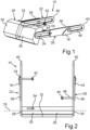
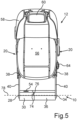
- the lower leg support 10 comprises a first fixing element 16 and a second fixing element 18.
- the first fixing element 16 and the second fixing element 18 serve to fix, i.e. to hold, the lower leg support 10 at opposite, in the Fig. 3 shown side areas 20 of the vehicle seat 12 and thus for holding the lower leg support 10 on or opposite the vehicle seat 12.
- a first displacement element 22 is rotatably connected to the first fixing element 16, in particular via a rotary joint 24.
- a second displacement element 26 is fixedly connected to the second fixing element 18.
- fixed means essentially non-rotatable for the second displacement element 26.
- a first rotatably held support element 30 is provided at an end 28 of the first displacement element 22 which is opposite the first fixing element 16 in a position of use.
- the first support element 30 can be locked to a second support element 36 which is rotatably arranged at an end 34 of the second displacement element 26 which is facing away from the second fixing element 18 in the position of use.
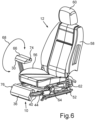
- the first support element which is unlocked by the second support element 36, can be moved in the use position by rotating the first displacement element 22 relative to the first fixing element 16 into a table position, which Fig. 6 to 8 shown, can be laid.
- the respective displacement element 22 and 26 is formed from a guide element 38 connected to the respective fixing element 16 and 18 and a support arm 40 which can be moved relative to the guide element 38 and which has the respective end 28 and 34 on which the respective support element 30 or 36 is arranged.
- drives 42 and 44 are provided.
- the first drive 42 serves to move the first support element 30 from the use position to the table position and back.
- the second drive 44 serves to move the two interlocked support elements 30 and 36 between the use position and the non-use position, in which, as in Fig. 3 shown, the support elements 30 and 36 rest on or below a seat element 56 of the vehicle seat 12.
- the second support arm 40 of the second displacement element 26 has a toothing 46, additionally or alternatively a rack and additionally or alternatively a spindle 48, via which the displacement between the use position and the non-use position by means of the second drive 44 can be carried out or mediated.
- a further toothing and/or a further rack and/or a further spindle can be provided in order to be able to carry out or mediate the displacement between the use position and the table position by means of the first drive 42.
- the locking device 32 advantageously has an operating element 54 for locking or unlocking, i.e. for opening and closing the locking device 32 and thus for connecting and/or separating the two support elements 30 and 36 to one another or to each other.
- the two support elements 30 and 36 can be rotated about a rotation axis 78.
- the rotation axis 78 can be split when the locking device 32 is open and the separation of the two support elements 30 and 36 is thereby possible.
- Fig. 3 shows in a schematic perspective view the lower leg support 10 arranged on the vehicle seat 12.
- the Fig. 3 furthermore a schematic arrangement of the vehicle seat 12 in the schematically illustrated motor vehicle 14.
- the vehicle seat 12 shown has a length adjustment device 50 which has length adjustment rails 52. So that the lower leg support 10 can be held or fixed particularly advantageously on the vehicle seat 12, the first fixing element 16 is fixed to a first of the length adjustment rails 52 on a first of the side regions 20. The second fixing element 18, on the other hand, is fixed to a second of the length adjustment rails 52 on the second side region 20.
- the first fixing element 16 of the motor vehicle 14, which has the vehicle seat 12 is arranged on a side of the vehicle seat 12 facing away from a vehicle door and thus, in contrast to a door side, on the tunnel side.
- the vehicle seat 12 can further comprise, in addition to the seat element 56, a backrest 58 and a headrest 60. Furthermore, the seat element 56 can have a frame element 62, which is arranged on the length adjustment device 50 via the length adjustment rails 52. Furthermore, the Vehicle seat 12 may have partially shown trim elements and/or an adjustment element 64 for the length adjustment device.
- a first step the two connected, locked, support elements 30 and 36 are moved by means of the drive 44 into the Fig. 4
- the position shown in the illustration is fully extended.
- the Fig. 3 the lower leg support or its support elements 30 and 36 in the non-use position.
- the displacement or movement between the use position and the non-use position advantageously takes place along a displacement direction 72.
- the Fig. 5 shows how, in a second step of the method, the locking device 32 is actuated via the operating element 54, which is located in the Fig. 1 to 4 is in a locked or closed position, is unlocked.
- the first support element 30 is moved from the use position to the table position, in particular by the first drive 42.
- the table position is in the Fig. 6 as well as in the Fig 7 and 8 shown.
- Fig. 6 further shows how, in a fourth step, by rotating the first support element 30 along the direction of rotation 68 indicated by an arrow, the support element 30 is rotated from a lower leg support position, in which, for example, a padded side of the support element 30 faces a vehicle roof liner, into a table top position. In the table top position, one, in particular table top-like, side of the support element 30 faces the vehicle roof liner. This is shown in Fig. 7 shown.
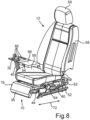
- a table extension element 66 can be unfolded along a folding direction 70 indicated by an arrow in order to, as in Fig. 8 to create a particularly wide usable table surface.
- the invention can also be implemented in such a way that the Fig. 6 shown turning in the direction of rotation 68 is omitted.
- a length adjustment can be carried out.
- the result of the length adjustment shows Fig. 8 .
- a distance between the seat element 56 and the second support element 36 is set by moving the displacement element 26 along the displacement direction 72, whereby a use position can be assumed which deviates from the use position.
- the use position can be the use position or a position of the support element 36 or the support elements 30 and 36 that is different from the non-use position.
- the displacement direction 72 is the direction along which the support elements 30 and 36 are displaced between the non-use position and the use position. In this case, even when the two support elements 30 and 36 are locked, a use position of the support elements 30 and 36 can be adjusted between the use position and the non-use position for supporting the lower legs, in particular depending on a leg length of the vehicle occupant.
- the first support element 30 has a first connecting surface 74, which is aligned congruently or in alignment with a second connecting surface 76 of the second support element 36, while the two support elements 30 and 36 are locked together, this shows Fig. 5
- the two connecting surfaces 74 and 76 serve to form an overlapping area so that the two connecting surfaces 74 and 76 touch each other when the first support element 30 is moved from the table position to the use position and the support elements 30 and 36 can thus be moved towards each other for a particularly simple locking of the locking device 32. This is achieved by the orientation of the connecting surfaces 74 and 76 to each other in the Fig. 6 and 7 clarified.
- the second support element 36 is wider than the first support element 30, in particular the second support element 36 is twice as wide as the first support element 30.
- the entire width of the lower leg support 10 is formed by one third of the first support element 30 and two thirds of the second support element 32. Due to the width of the wider, second support element 36, when the first support element 30 is used in the table position, there is enough space to rest the two lower legs of the vehicle occupant.
- the first support element 30 has a foldable table extension element 66.
- storage recesses 80 can also be provided for storing objects, in particular, for example, beverage cups.
- the figures show a lower leg support 10, a vehicle seat 12 and a motor vehicle 14.
- a support bearing in the form of the support elements 30 and 36 is arranged on the right and left of the vehicle seat 12 on moving length adjustment rails 52.
- a guide element 38 is connected to each of these support bearings, with the guide element 38 on the door side being firmly connected to the support bearing and/or being designed as a single piece.
- the guide element 38 is connected to the support bearing via the swivel joint 24.
- the guide element 38 on the tunnel side is connected, in particular firmly, to the drive 42, which pivots it up for the table function.
- the support arms 40 of the calf support or the lower leg support 10 are moved with these guide elements 38.
- the calf support is thus moved from the non-use position, in which the support elements 30 and 36 are located in particular directly on the seat cushion or the seat element 56, into the position desired by the vehicle occupant, up to the maximum position of use.
- the actual calf support is rotatably mounted, in particular about the respective axis of rotation 78.
- the lower leg support or its calf support formed from the support elements 30 and 36 can thus automatically align itself to a particularly advantageous angle for the vehicle occupant due to the rotatability.
- the support arm 40 for a forward and backward movement between the position of use and the non-use position, is preferably equipped with the gearing 46, which serves to carry out the displacement via the drive 44.
- the support arm 40 can be equipped with a rack or additionally or alternatively with the spindle 48 for the drive.
- the actual calf support advantageously comprises a two-thirds-one-third division of the support elements 30 and 36, whereby the two-thirds support element 36 serves exclusively as a calf support, while the one-third support element 30 can be used both as a calf support and as a table.
- the calf support must first be brought into the frontmost position, i.e. the position of use. Then a locking mechanism, the locking device 32, must be opened to divide the calf support formed by the support elements 30 and 36.
- the vehicle occupant should move his legs slightly towards the door-side part of the lower leg support 10.
- the table which is essentially formed by the support element 30, can then be swiveled up into the table position using the drive 42.
- this part of the calf support is rotated in particular by 180 degrees and can be folded out again to enlarge the table surface.
- the design can be implemented in such a way that the 180° rotation is dispensed with and the 1/3 calf support serves directly as a table surface, or the table surface is created by folding it up. Since the support arm 40 for the table function is advantageously arranged on the tunnel side, it is also easy to get in and out of the vehicle seat 12 while the table function is being used.
- the support element 30 While the support element 30 is in the table position, the door-side part of the calf support, the support element 36, can be moved forwards and backwards as required to achieve an advantageous position of use.
- the support element 30 In order to restore the original calf support function, the support element 30 is pivoted down by rotation and the support element 36, if it is in a position of use that differs from the position of use, is brought into the position of use and thus into the frontmost position, which for example is in the Fig. 4 to 7 In contrast, the Fig. 8 a use position that is different from the use position.
- the two support elements 30 and 36 can be positioned particularly easily relative to one another due to the inclined connecting surfaces 74 and 76, so that in the frontmost position - in the use position - of the two support elements 30 and 36, they find each other practically in a movement-controlled manner from a certain swivel angle setting. Now the locking device 32 can be closed again and the The calf support of the lower leg support 10 formed by support elements 30 and 36 can be used like a conventional calf support.
- a lower leg support 10 for a vehicle seat 12 is shown, with a first fixing element 16 and with a second fixing element 18, which are designed to fix the lower leg support 10 to the vehicle seat 12, a first displacement element 22 is rotatably connected to the first fixing element 16 and a second displacement element 26 is firmly connected to the second fixing element 18, at a first end 28 of the first displacement element 22 there is a first support element 30 which is rotatably held thereon and which can be locked by means of a locking device 32 to a second support element 36 which is rotatably arranged at a second end 34 of the second displacement element 26, wherein the two support elements 30, 36 can be displaced from a use position into a non-use position by means of the displacement elements 22, 26 and the first support element 30 can additionally be displaced from the use position into a table position. can be laid.
- the lower leg support 10 shown can also be used in the same way on a vehicle seat without a length adjustment device 50 which, in contrast to the embodiment of the vehicle seat 12, is fixed; in this case, the fixing elements 16 and 18 and, for example, in particular also the drives 42 and 44 are connected directly to a floor connection of the vehicle seat.
- the lower leg support 10 shown, the vehicle seat 12 and the motor vehicle 14 offer a particularly high level of comfort and a particular range of functions while at the same time being particularly compact in terms of installation space and weight.
Landscapes
- Engineering & Computer Science (AREA)
- Transportation (AREA)
- Mechanical Engineering (AREA)
- Aviation & Aerospace Engineering (AREA)
- Seats For Vehicles (AREA)
- Passenger Equipment (AREA)
Claims (10)
- Repose-jambes (10) pour un siège de véhicule (12), comportant un premier élément de fixation (16) et comportant un second élément de fixation (18), qui sont conçus pour la fixation du repose-jambes (10) sur des zones latérales opposées (20) du siège de véhicule (12), dans lequel un premier élément de déplacement (22) est relié de manière rotative au premier élément de fixation (16) et un second élément de déplacement (26) est relié de manière fixe au second élément de fixation (18),
dans lequel
au niveau d'une extrémité (28) du premier élément de déplacement (22) opposée au premier élément de fixation (16) dans une position d'utilisation, il est prévu un premier élément d'appui (30) maintenu sur celui-ci de manière rotative, lequel est verrouillable mutuellement à l'aide d'un dispositif de verrouillage (32) avec un second élément d'appui (36) disposé de manière rotative au niveau d'une extrémité (34) du second élément de déplacement (26) opposée au second élément de fixation (18) dans la position d'utilisation, dans lequel les deux éléments d'appui (30, 36) sont déplaçables de la position d'utilisation dans une position de non-utilisation à l'aide des éléments de déplacement (22, 26) et le premier élément d'appui (30), déverrouillé par le second élément d'appui (36), est transférable dans une position de table dans la position d'utilisation par rotation du premier élément de déplacement (22) par rapport au premier élément de fixation (16). - Repose-jambes (10) selon la revendication 1,
caractérisé en ce que
le premier élément d'appui (30) présente un élément d'extension de surface de table (66), en particulier rabattable. - Repose-jambes (10) selon la revendication 1 ou 2,
caractérisé en ce que
l'élément de déplacement (22, 26) respectif est conçu d'un élément de guidage (38) relié à l'élément de fixation (16, 18) respectif et d'un bras d'appui (40) déplaçable par rapport à l'élément de guidage (38), lequel présente respectivement l'extrémité (28, 34) respective sur laquelle est disposé l'élément d'appui (30, 36) respectif. - Repose-jambes (10) selon l'une des revendications précédentes,
caractérisé en ce
qu'un premier entraînement (42) est prévu, à l'aide duquel le premier élément d'appui (30) est déplaçable de la position d'utilisation à la position de table et/ou un second entraînement (44) est prévu, à l'aide duquel les deux éléments d'appui (30, 36) verrouillés ensemble sont déplaçables entre la position d'utilisation et la position de non-utilisation. - Repose-jambes (10) selon la revendication 3 et la revendication 4,
caractérisé en ce que
le second bras d'appui (40) présente une denture (46) et/ou une crémaillère et/ou une broche (48), par l'intermédiaire desquelles le déplacement entre la position d'utilisation et la position de non-utilisation est réalisable à l'aide du second entraînement (44). - Repose-jambes (10) selon l'une des revendications précédentes,
caractérisé en ce que
le premier élément d'appui (30) présente une première surface de liaison (74) laquelle est orientée de manière à coïncider avec une seconde surface de liaison (76) du second élément d'appui (36) pendant que les deux éléments d'appui (30, 36) sont verrouillés l'un à l'autre et/ou les deux surfaces de liaison (74, 76) présentent une zone de chevauchement par laquelle les surfaces de liaison (74, 76) se touchent lors du déplacement du premier élément d'appui (30), de la position de table à la position d'utilisation, et les éléments d'appui (30, 36) sont ainsi mobiles l'un vers l'autre pour le verrouillage du dispositif de verrouillage (32). - Repose-jambes (10) selon l'une des revendications précédentes,
caractérisé en ce que
le second élément d'appui (36) est plus large que le premier élément d'appui (30) et présente en particulier une largeur double. - Siège de véhicule (12) comprenant un repose-jambes (10) selon l'une des revendications précédentes, dans lequel les éléments de fixation (16, 18) sont fixés à une liaison au sol du siège de véhicule (12) ou le siège de véhicule (12) présente un dispositif de réglage de la longueur (50) comportant des rails de réglage de la longueur (52) et le premier élément de fixation (16) est fixé à un premier des rails de réglage de la longueur (52) et le second élément de fixation (18) est fixé à un second des rails de réglage de la longueur (52).
- Véhicule automobile (14) comprenant un repose-jambes (10) selon l'une des revendications 1 à 7 et/ou un siège de véhicule (12) selon la revendication 8.
- Véhicule automobile (14) selon la revendication 9 ;
caractérisé en ce que
le premier élément de fixation (16) est disposé sur un côté du siège de véhicule (12) opposé à une porte de véhicule.
Applications Claiming Priority (2)
| Application Number | Priority Date | Filing Date | Title |
|---|---|---|---|
| DE102021001908.3A DE102021001908B4 (de) | 2021-04-13 | 2021-04-13 | Unterschenkelstütze für einen Fahrzeugsitz, Fahrzeugsitz eines Kraftfahrzeugs sowie Kraftfahrzeug |
| PCT/EP2022/057000 WO2022218637A1 (fr) | 2021-04-13 | 2022-03-17 | Support de jambes pour un siège de véhicule, siège de véhicule d'un véhicule automobile et véhicule automobile |
Publications (3)
| Publication Number | Publication Date |
|---|---|
| EP4323235A1 EP4323235A1 (fr) | 2024-02-21 |
| EP4323235B1 true EP4323235B1 (fr) | 2024-10-09 |
| EP4323235C0 EP4323235C0 (fr) | 2024-10-09 |
Family
ID=81308137
Family Applications (1)
| Application Number | Title | Priority Date | Filing Date |
|---|---|---|---|
| EP22716364.9A Active EP4323235B1 (fr) | 2021-04-13 | 2022-03-17 | Support de jambes pour un siège de véhicule, siège de véhicule d'un véhicule automobile et véhicule automobile |
Country Status (5)
| Country | Link |
|---|---|
| US (1) | US12508968B2 (fr) |
| EP (1) | EP4323235B1 (fr) |
| CN (1) | CN117177880A (fr) |
| DE (1) | DE102021001908B4 (fr) |
| WO (1) | WO2022218637A1 (fr) |
Families Citing this family (2)
| Publication number | Priority date | Publication date | Assignee | Title |
|---|---|---|---|---|
| DE102023120222A1 (de) | 2023-03-28 | 2024-10-02 | Kokinetics Gmbh | Wadenstütze für einen Fahrzeugsitz und ein Fahrzeugsitz umfassend eine Wadenstütze |
| US20250263000A1 (en) * | 2024-02-19 | 2025-08-21 | Ford Global Technologies, Llc | Seating assembly having lower leg support |
Family Cites Families (18)
| Publication number | Priority date | Publication date | Assignee | Title |
|---|---|---|---|---|
| US2403263A (en) | 1944-11-13 | 1946-07-02 | Collins Calhoun | Combined leg rest and table |
| US3794381A (en) * | 1971-10-26 | 1974-02-26 | D Caldemeyer | Footrest for reclining chair |
| US5507562A (en) * | 1994-07-28 | 1996-04-16 | Wieland Designs Inc. | Extensible foot rest |
| JPH09169233A (ja) | 1995-12-20 | 1997-06-30 | Showa Aircraft Ind Co Ltd | 座席足下の昇降体構造 |
| JP3563205B2 (ja) | 1996-06-10 | 2004-09-08 | 関東自動車工業株式会社 | 自動車用室内テーブル |
| DE20001130U1 (de) | 2000-01-24 | 2000-05-18 | Gebr. Heymann GmbH, 56357 Geisig | Schwenkbare kombinierte Tisch-Beinauflage für Omnibusse |
| DE10056412B4 (de) | 2000-11-14 | 2007-08-23 | Daimlerchrysler Ag | Fußabstellvorrichtung |
| JP4350418B2 (ja) | 2003-05-14 | 2009-10-21 | 株式会社三誠 | 検診台 |
| JP2006143108A (ja) | 2004-11-24 | 2006-06-08 | Mazda Motor Corp | 車両のシート装置 |
| JP2006271497A (ja) | 2005-03-28 | 2006-10-12 | Coleman Co Inc:The | フットレスト付き折畳みチェア |
| DE102010030553B4 (de) | 2010-06-25 | 2017-03-09 | Brose Fahrzeugteile Gmbh & Co. Kommanditgesellschaft, Coburg | Unterschenkelstütze für einen Fahrzeugsitz |
| CN204095593U (zh) * | 2014-07-29 | 2015-01-14 | 比亚迪股份有限公司 | 一种汽车座椅及汽车 |
| JP6477215B2 (ja) | 2015-05-07 | 2019-03-06 | トヨタ紡織株式会社 | 乗物用シート |
| US10479225B2 (en) * | 2016-10-18 | 2019-11-19 | Ford Global Technologies, Llc | Method of configuring a vehicle seating assembly |
| US10479250B2 (en) * | 2018-04-19 | 2019-11-19 | Dae Won San Up Co., Ltd. | Structure of leg-rest |
| DE102019206121B4 (de) * | 2019-04-29 | 2024-07-11 | Volkswagen Aktiengesellschaft | Multifunktionaler Relax-Sitz |
| DE102019126180A1 (de) | 2019-09-27 | 2021-04-01 | Bayerische Motoren Werke Aktiengesellschaft | Kraftfahrzeugsitz |
| DE102019133470A1 (de) | 2019-12-09 | 2021-06-10 | Audi Ag | Ablageanordnung für einen Fahrzeugsitz |
-
2021
- 2021-04-13 DE DE102021001908.3A patent/DE102021001908B4/de active Active
-
2022
- 2022-03-17 WO PCT/EP2022/057000 patent/WO2022218637A1/fr not_active Ceased
- 2022-03-17 CN CN202280028096.5A patent/CN117177880A/zh active Pending
- 2022-03-17 US US18/555,127 patent/US12508968B2/en active Active
- 2022-03-17 EP EP22716364.9A patent/EP4323235B1/fr active Active
Also Published As
| Publication number | Publication date |
|---|---|
| DE102021001908A1 (de) | 2022-10-13 |
| CN117177880A (zh) | 2023-12-05 |
| EP4323235C0 (fr) | 2024-10-09 |
| US12508968B2 (en) | 2025-12-30 |
| EP4323235A1 (fr) | 2024-02-21 |
| US20240217421A1 (en) | 2024-07-04 |
| WO2022218637A1 (fr) | 2022-10-20 |
| DE102021001908B4 (de) | 2022-12-22 |
Similar Documents
| Publication | Publication Date | Title |
|---|---|---|
| DE10355819B4 (de) | Fahrzeugsitz, insbesondere Kraftfahrzeugsitz | |
| EP2066527B1 (fr) | Siege de vehicule a dossier rotatif et essentiellement decalable | |
| DE102018112926A1 (de) | Fahrzeugsitz | |
| EP3509902A1 (fr) | Siège de véhicule | |
| DE102019122542B4 (de) | Fahrzeugsitz und Nutzfahrzeugkabine mit Fahrzeugsitz | |
| EP3626523B1 (fr) | Siège de véhicule pour cabines des véhicules utilitaires | |
| DE102017215929A1 (de) | Vorschwenkbarer Fahrzeugsitz | |
| EP2707250B1 (fr) | Siège de véhicule, en particulier siège de véhicule automobile | |
| EP1817198A1 (fr) | Siege de vehicule, notamment siege de vehicule automobile | |
| EP2183127A1 (fr) | Siège de véhicule pour véhicule automobile | |
| EP2801293A1 (fr) | Elément de siège et sa garniture | |
| DE102012109382A1 (de) | Klapptisch | |
| EP4323235B1 (fr) | Support de jambes pour un siège de véhicule, siège de véhicule d'un véhicule automobile et véhicule automobile | |
| DE19758237A1 (de) | Kraftfahrzeugsitz | |
| DE102018203170A1 (de) | Tischanordnung für den Innenraum eines Fahrzeugs | |
| EP1718494A1 (fr) | Siege de vehicule, notamment pour une automobile, comprenant un dossier rabattable et une base d'assise rabattable et procede correspondant | |
| DE102005029235B4 (de) | Armlehne für einen Fahrzeugsitz und Fahrzeugsitz | |
| DE112023004123T5 (de) | Zero-Gravity-Fahrzeugsitz und dessen Sitzskelett | |
| EP3945942A1 (fr) | Châssis de meuble d'assise | |
| DE102007005209A1 (de) | Easy-Entry-Stellung eines Kraftfahrzeugsitzes | |
| WO2016184745A1 (fr) | Siège de poste de conduite, poste de conduite et installation | |
| DE10318718A1 (de) | Verstellbarer Kraftfahrzeugsitz, insbesondere für die zweite und dritte Sitzreihe | |
| EP3626522B1 (fr) | Construction de dossier pour un siège de véhicule | |
| DE102020117825B4 (de) | Fahrzeugsitz mit einer klappbaren Rückenlehne und einem mit derselben gekoppelten und absenkbaren Armlehnenkörper | |
| DE102004039246B4 (de) | Fahrzeugsitz, insbesondere Kraftfahrzeugsitz |
Legal Events
| Date | Code | Title | Description |
|---|---|---|---|
| STAA | Information on the status of an ep patent application or granted ep patent |
Free format text: STATUS: UNKNOWN |
|
| STAA | Information on the status of an ep patent application or granted ep patent |
Free format text: STATUS: THE INTERNATIONAL PUBLICATION HAS BEEN MADE |
|
| PUAI | Public reference made under article 153(3) epc to a published international application that has entered the european phase |
Free format text: ORIGINAL CODE: 0009012 |
|
| STAA | Information on the status of an ep patent application or granted ep patent |
Free format text: STATUS: REQUEST FOR EXAMINATION WAS MADE |
|
| 17P | Request for examination filed |
Effective date: 20230918 |
|
| AK | Designated contracting states |
Kind code of ref document: A1 Designated state(s): AL AT BE BG CH CY CZ DE DK EE ES FI FR GB GR HR HU IE IS IT LI LT LU LV MC MK MT NL NO PL PT RO RS SE SI SK SM TR |
|
| GRAP | Despatch of communication of intention to grant a patent |
Free format text: ORIGINAL CODE: EPIDOSNIGR1 |
|
| STAA | Information on the status of an ep patent application or granted ep patent |
Free format text: STATUS: GRANT OF PATENT IS INTENDED |
|
| DAV | Request for validation of the european patent (deleted) | ||
| DAX | Request for extension of the european patent (deleted) | ||
| INTG | Intention to grant announced |
Effective date: 20240415 |
|
| GRAS | Grant fee paid |
Free format text: ORIGINAL CODE: EPIDOSNIGR3 |
|
| GRAA | (expected) grant |
Free format text: ORIGINAL CODE: 0009210 |
|
| STAA | Information on the status of an ep patent application or granted ep patent |
Free format text: STATUS: THE PATENT HAS BEEN GRANTED |
|
| AK | Designated contracting states |
Kind code of ref document: B1 Designated state(s): AL AT BE BG CH CY CZ DE DK EE ES FI FR GB GR HR HU IE IS IT LI LT LU LV MC MK MT NL NO PL PT RO RS SE SI SK SM TR |
|
| REG | Reference to a national code |
Ref country code: CH Ref legal event code: EP |
|
| REG | Reference to a national code |
Ref country code: DE Ref legal event code: R096 Ref document number: 502022001864 Country of ref document: DE |
|
| REG | Reference to a national code |
Ref country code: IE Ref legal event code: FG4D Free format text: LANGUAGE OF EP DOCUMENT: GERMAN |
|
| U01 | Request for unitary effect filed |
Effective date: 20241031 |
|
| U07 | Unitary effect registered |
Designated state(s): AT BE BG DE DK EE FI FR IT LT LU LV MT NL PT RO SE SI Effective date: 20241112 |
|
| PG25 | Lapsed in a contracting state [announced via postgrant information from national office to epo] |
Ref country code: IS Free format text: LAPSE BECAUSE OF FAILURE TO SUBMIT A TRANSLATION OF THE DESCRIPTION OR TO PAY THE FEE WITHIN THE PRESCRIBED TIME-LIMIT Effective date: 20250209 Ref country code: HR Free format text: LAPSE BECAUSE OF FAILURE TO SUBMIT A TRANSLATION OF THE DESCRIPTION OR TO PAY THE FEE WITHIN THE PRESCRIBED TIME-LIMIT Effective date: 20241009 |
|
| PG25 | Lapsed in a contracting state [announced via postgrant information from national office to epo] |
Ref country code: ES Free format text: LAPSE BECAUSE OF FAILURE TO SUBMIT A TRANSLATION OF THE DESCRIPTION OR TO PAY THE FEE WITHIN THE PRESCRIBED TIME-LIMIT Effective date: 20241009 |
|
| PG25 | Lapsed in a contracting state [announced via postgrant information from national office to epo] |
Ref country code: NO Free format text: LAPSE BECAUSE OF FAILURE TO SUBMIT A TRANSLATION OF THE DESCRIPTION OR TO PAY THE FEE WITHIN THE PRESCRIBED TIME-LIMIT Effective date: 20250109 |
|
| PG25 | Lapsed in a contracting state [announced via postgrant information from national office to epo] |
Ref country code: GR Free format text: LAPSE BECAUSE OF FAILURE TO SUBMIT A TRANSLATION OF THE DESCRIPTION OR TO PAY THE FEE WITHIN THE PRESCRIBED TIME-LIMIT Effective date: 20250110 |
|
| PG25 | Lapsed in a contracting state [announced via postgrant information from national office to epo] |
Ref country code: PL Free format text: LAPSE BECAUSE OF FAILURE TO SUBMIT A TRANSLATION OF THE DESCRIPTION OR TO PAY THE FEE WITHIN THE PRESCRIBED TIME-LIMIT Effective date: 20241009 |
|
| PG25 | Lapsed in a contracting state [announced via postgrant information from national office to epo] |
Ref country code: RS Free format text: LAPSE BECAUSE OF FAILURE TO SUBMIT A TRANSLATION OF THE DESCRIPTION OR TO PAY THE FEE WITHIN THE PRESCRIBED TIME-LIMIT Effective date: 20250109 |
|
| U20 | Renewal fee for the european patent with unitary effect paid |
Year of fee payment: 4 Effective date: 20250325 |
|
| PG25 | Lapsed in a contracting state [announced via postgrant information from national office to epo] |
Ref country code: SM Free format text: LAPSE BECAUSE OF FAILURE TO SUBMIT A TRANSLATION OF THE DESCRIPTION OR TO PAY THE FEE WITHIN THE PRESCRIBED TIME-LIMIT Effective date: 20241009 |
|
| PG25 | Lapsed in a contracting state [announced via postgrant information from national office to epo] |
Ref country code: SK Free format text: LAPSE BECAUSE OF FAILURE TO SUBMIT A TRANSLATION OF THE DESCRIPTION OR TO PAY THE FEE WITHIN THE PRESCRIBED TIME-LIMIT Effective date: 20241009 |
|
| PG25 | Lapsed in a contracting state [announced via postgrant information from national office to epo] |
Ref country code: CZ Free format text: LAPSE BECAUSE OF FAILURE TO SUBMIT A TRANSLATION OF THE DESCRIPTION OR TO PAY THE FEE WITHIN THE PRESCRIBED TIME-LIMIT Effective date: 20241009 |
|
| PLBE | No opposition filed within time limit |
Free format text: ORIGINAL CODE: 0009261 |
|
| STAA | Information on the status of an ep patent application or granted ep patent |
Free format text: STATUS: NO OPPOSITION FILED WITHIN TIME LIMIT |
|
| 26N | No opposition filed |
Effective date: 20250710 |
|
| PG25 | Lapsed in a contracting state [announced via postgrant information from national office to epo] |
Ref country code: MC Free format text: LAPSE BECAUSE OF FAILURE TO SUBMIT A TRANSLATION OF THE DESCRIPTION OR TO PAY THE FEE WITHIN THE PRESCRIBED TIME-LIMIT Effective date: 20241009 |
|
| REG | Reference to a national code |
Ref country code: CH Ref legal event code: H13 Free format text: ST27 STATUS EVENT CODE: U-0-0-H10-H13 (AS PROVIDED BY THE NATIONAL OFFICE) Effective date: 20251023 |
|
| PG25 | Lapsed in a contracting state [announced via postgrant information from national office to epo] |
Ref country code: CH Free format text: LAPSE BECAUSE OF NON-PAYMENT OF DUE FEES Effective date: 20250331 |
|
| PG25 | Lapsed in a contracting state [announced via postgrant information from national office to epo] |
Ref country code: IE Free format text: LAPSE BECAUSE OF NON-PAYMENT OF DUE FEES Effective date: 20250317 |
|
| U20 | Renewal fee for the european patent with unitary effect paid |
Year of fee payment: 5 Effective date: 20260323 |