EP3626845A1 - Poudre d'alliage d'hydrure métallique pour batteries nimh ayant des propriétés améliorées, son procédé de préparation et batterie nimh ayant des propriétés améliorées comprenant de la poudre d'alliage d'hydrure métallique - Google Patents
Poudre d'alliage d'hydrure métallique pour batteries nimh ayant des propriétés améliorées, son procédé de préparation et batterie nimh ayant des propriétés améliorées comprenant de la poudre d'alliage d'hydrure métallique Download PDFInfo
- Publication number
- EP3626845A1 EP3626845A1 EP18196021.2A EP18196021A EP3626845A1 EP 3626845 A1 EP3626845 A1 EP 3626845A1 EP 18196021 A EP18196021 A EP 18196021A EP 3626845 A1 EP3626845 A1 EP 3626845A1
- Authority
- EP
- European Patent Office
- Prior art keywords
- hydrogen storage
- alloy powder
- storage alloy
- nimh
- hydrogen
- Prior art date
- Legal status (The legal status is an assumption and is not a legal conclusion. Google has not performed a legal analysis and makes no representation as to the accuracy of the status listed.)
- Withdrawn
Links
Images
Classifications
-
- C—CHEMISTRY; METALLURGY
- C22—METALLURGY; FERROUS OR NON-FERROUS ALLOYS; TREATMENT OF ALLOYS OR NON-FERROUS METALS
- C22C—ALLOYS
- C22C1/00—Making non-ferrous alloys
- C22C1/10—Alloys containing non-metals
- C22C1/1026—Alloys containing non-metals starting from a solution or a suspension of (a) compound(s) of at least one of the alloy constituents
-
- H—ELECTRICITY
- H01—ELECTRIC ELEMENTS
- H01M—PROCESSES OR MEANS, e.g. BATTERIES, FOR THE DIRECT CONVERSION OF CHEMICAL ENERGY INTO ELECTRICAL ENERGY
- H01M10/00—Secondary cells; Manufacture thereof
- H01M10/34—Gastight accumulators
- H01M10/345—Gastight metal hydride accumulators
-
- H—ELECTRICITY
- H01—ELECTRIC ELEMENTS
- H01M—PROCESSES OR MEANS, e.g. BATTERIES, FOR THE DIRECT CONVERSION OF CHEMICAL ENERGY INTO ELECTRICAL ENERGY
- H01M4/00—Electrodes
- H01M4/02—Electrodes composed of, or comprising, active material
-
- H—ELECTRICITY
- H01—ELECTRIC ELEMENTS
- H01M—PROCESSES OR MEANS, e.g. BATTERIES, FOR THE DIRECT CONVERSION OF CHEMICAL ENERGY INTO ELECTRICAL ENERGY
- H01M4/00—Electrodes
- H01M4/02—Electrodes composed of, or comprising, active material
- H01M4/24—Electrodes for alkaline accumulators
- H01M4/242—Hydrogen storage electrodes
-
- H—ELECTRICITY
- H01—ELECTRIC ELEMENTS
- H01M—PROCESSES OR MEANS, e.g. BATTERIES, FOR THE DIRECT CONVERSION OF CHEMICAL ENERGY INTO ELECTRICAL ENERGY
- H01M4/00—Electrodes
- H01M4/02—Electrodes composed of, or comprising, active material
- H01M4/24—Electrodes for alkaline accumulators
- H01M4/26—Processes of manufacture
-
- H—ELECTRICITY
- H01—ELECTRIC ELEMENTS
- H01M—PROCESSES OR MEANS, e.g. BATTERIES, FOR THE DIRECT CONVERSION OF CHEMICAL ENERGY INTO ELECTRICAL ENERGY
- H01M4/00—Electrodes
- H01M4/02—Electrodes composed of, or comprising, active material
- H01M4/36—Selection of substances as active materials, active masses, active liquids
- H01M4/38—Selection of substances as active materials, active masses, active liquids of elements or alloys
- H01M4/383—Hydrogen absorbing alloys
-
- H—ELECTRICITY
- H01—ELECTRIC ELEMENTS
- H01M—PROCESSES OR MEANS, e.g. BATTERIES, FOR THE DIRECT CONVERSION OF CHEMICAL ENERGY INTO ELECTRICAL ENERGY
- H01M4/00—Electrodes
- H01M4/02—Electrodes composed of, or comprising, active material
- H01M4/36—Selection of substances as active materials, active masses, active liquids
- H01M4/38—Selection of substances as active materials, active masses, active liquids of elements or alloys
- H01M4/383—Hydrogen absorbing alloys
- H01M4/385—Hydrogen absorbing alloys of the type LaNi5
-
- Y—GENERAL TAGGING OF NEW TECHNOLOGICAL DEVELOPMENTS; GENERAL TAGGING OF CROSS-SECTIONAL TECHNOLOGIES SPANNING OVER SEVERAL SECTIONS OF THE IPC; TECHNICAL SUBJECTS COVERED BY FORMER USPC CROSS-REFERENCE ART COLLECTIONS [XRACs] AND DIGESTS
- Y02—TECHNOLOGIES OR APPLICATIONS FOR MITIGATION OR ADAPTATION AGAINST CLIMATE CHANGE
- Y02E—REDUCTION OF GREENHOUSE GAS [GHG] EMISSIONS, RELATED TO ENERGY GENERATION, TRANSMISSION OR DISTRIBUTION
- Y02E60/00—Enabling technologies; Technologies with a potential or indirect contribution to GHG emissions mitigation
- Y02E60/10—Energy storage using batteries
Definitions
- the invention concerns a method for improving the properties of metal hydride (MH) alloys for hydride batteries, in particular nickel-metal hydride (NiMH) batteries. It also concerns a MH alloy having improved properties that may be obtained from the method, as well as a NiMH battery having improved properties. The invention furthermore concerns the use of hydrogen peroxide for improving the properties of a MH alloy.
- MH metal hydride
- NiMH nickel-metal hydride
- Nickel-metal hydride (NiMH) batteries are important power sources in electronic devices as well as hybrid electrical vehicles or fully electric (EV) vehicles.
- NiMH batteries One drawback of NiMH batteries is their degradation and capacity loss over time, as well as poor low-temperature properties.
- the cathode of a NiMH battery is formed of Nickel (II) hydroxide (Ni(OH) 2 ) and Nickel (III) oxide hydroxide (NiOOH), while the anode of a NiMH battery during discharge is commonly based on A x B y alloys of different types that are able to store hydrogen in hydride form.
- a x B y alloys of different types that are able to store hydrogen in hydride form.
- a x B y alloys of different types that are able to store hydrogen in hydride form.
- A x B y alloy
- A is selected from electropositive rare earth elements (e.g. La to Nd).
- B is predominantly Ni, but may partly be substituted by Co, Fe, Mn, Si, Mg and/or Al to improve hydrogen storage performance and corrosion stability.
- a x B y alloy is [La 0.8 Nd 0.2 ][Ni 2.5 Co 2.4 Si 0.1 ].
- Other types of A x B y alloys include A 2 B 7 , wherein A and B are as defined above. Further known are alloys of type AB 2 .
- the present invention is concerned with the improvement of such hydrogen storage alloys, e.g. of type AB 5 , A 2 B 7 and AB 2 , alloys, which are also referred to as MH alloys in the following.
- a NiMH battery includes at least one anode, at least one cathode, and typically an aqueous alkaline electrolyte and a separator. Note that the anode upon discharge will become a cathode during charge, however, herein we will refer to the electrodes as they will function during discharge operation.
- the anode alloy surface is corroded by the alkaline electrolyte used in the batteries during cycling. This reduces the capacity and consumes water in electrolyte. The corrosion also leads to evolution of hydrogen, which can be absorbed in the anode, however, this unbalances the electrodes capacities and results in an internal pressure increase when charging the battery.
- the activation process and the overcharge of the battery also contribute to the internal pressure increase.
- the high internal pressure makes the battery to vent through the safety valve accelerating its dry-out. This causes capacity decay and short cycle life.
- Mm denotes a Misch metal, or a mixture of rare earth elements such as La, Ce, Nd, Pr, etc.
- the Ni-electrode balance is shifted to higher hydrogen pressures. Increased contamination of hydrogen reduces the oxygen recombination kinetics. The reduction in overcharge capacity increases internal pressure, which leads to gas venting from the safety valve. Corrosion and venting consume the electrolyte, resulting in an inner resistance increase and the reduction in capacity of a sealed NiMH battery. Further, as derivable from the above formula, water is consumed, leading to dry-out of the electrolyte. These effects lead to aging of the battery and a reduction in cycle life.
- WO01/89009 A1 describes a treatment with hot KOH solution on a hydride/dehydrided (HDH) and oxidized (HDK) MH alloy powder, referred to as HAK method in this document and also in the following.
- the HAK method leads to magnetic properties of the AB 5 alloy and improves the discharge properties of an electrode prepared from the HAK-treated alloy powder in a half-cell test (discharge capacity vs. discharge current), showing higher discharge currents at identical remaining discharge capacities in comparison to only HDH- or HDK-treated materials (see Fig. 1 of WO 01/89009 A1 ).
- An earlier attempt to improve MH alloy powders is described in US 4,716,088 .
- Hydrogen peroxide is a widely used inexpensive and environmentally friendly oxidizing agent.
- hydrogen peroxide is described as component of the alkaline aqueous electrolyte, as described in K. Young et al., Int. J. Hydrogen Energy, Volume 37, Issue 12, 2012, Pages 9882-9891 .
- metal hydride contents will be oxidized, and hydrogen peroxide might also oxidize the cathode material or the separator.
- the present invention aims at providing a method for improving the properties of a MH alloy powder, as well as an improved MH alloy powder, addressing one or more of the problems and drawbacks of the prior art.
- the present inventors have found that at least one of the above problems, and preferably some or all of the above problems, can be solved by treating a MH alloy powder suitable for use as an anode of a NiMH battery with aqueous hydrogen peroxide solution.
- the present invention thus provides the following
- H 2 O 2 hydrogen peroxide
- aqueous H 2 O 2 typically aqueous H 2 O 2 .
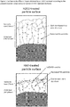
- the H 2 O 2 treatment leads to the formation of a relatively thick oxide layer, containing catalytic active nano-particles of e.g. nickel and/or cobalt, on the surface of the storage alloy powder particles, which however is sufficiently porous in order to not impair the accessibility or the electrochemical properties.
- the method for treating a hydrogen storage alloy powder for a negative electrode of a rechargeable NiMH battery of the present invention comprises the following step C, and optionally the steps A and/or B:
- the starting material for the method of the present invention is a hydrogen storage alloy of known type, and is preferably an alloy that contains Co and/or Ni.
- the alloy may be of the type AB 5 and AB 2 , preferably AB 5 . Included are also alloys having an alternate layers of AB 2 and AB 5 as described by D. G. Westlake with reference to Dunlap et al. in J. of the Less Common Metals, 91 (1983) 1-20 , such as in AB 3 , A 2 B 7 , A 2 B 9 , A 2 B 17 etc., most preferred is the alloy A 2 B 7 .
- the alloy type AB 5 includes those having a deviating stoichiometry ABy, where y is from 4.5 to 5.4, as described for instance by Wang et al. in Chem. Eng. J. 352 (2016) 325-332 and J. Power Sources 398 (2016) 42-48 . Similar deviation from ideal stoichiometry may occur also for the AB 2 and A 2 B 7 alloys, so that in one embodiment the AB 2 alloys may have a stoichiometry in the range of AB 1.8-2.2 , and in the A 2 B 7 alloys, the stoichiometry may be A 2 B 6.6-7.4 .
- the total amount of Co and Ni is preferably 50 mol% or more, such as 75 mol% or more, 85 mol% or more, or even 90 mol% or more, of the elements forming B in the above alloys, e.g. AB 5 and A 2 B 7 .
- These alloys combine a hydride forming metal A, usually selected from the group consisting of rare earth metals, preferably selected from the group of lanthanides consisting of La, Ce, Nd, Pr, etc, but also selected from Y, Zr or Ti, or their mixture with a non-hydride forming element B, which is typically nickel.
- the latter can be doped with or partially replaced by other metals, such as Co, Mn, Fe, V, Cr, Si, Ca, Sc, Mg or Al, e.g. to a degree of up to 30%, to improve materials stability or to adjust equilibrium hydrogen pressure and temperature required for its charging discharging with hydrogen, as well known in the art.
- A is preferably selected from La, Nd, Ce, Pr, and Y, and mixtures thereof, such as a mixture of La and/or Ce with Y.
- A is a mixture of at least one of La and Ce with at least one of Nd, Y and Zr, and herein the at least one of La and Ce forms 50 mol% or more of the elements forming A.
- the at least one of La and Ce may consist of La or Ce only, but also encompasses the possibility that both are present. In the latter case, the amount of La preferably exceeds that of Ce, and the molar ratio of La to Ce (La/Ce) may be 1 or higher, such as 1.5 to 5.
- B may be formed by Ni only, but the Ni may partly be substituted by Co, Fe, Mn, Si, and/or Al to improve e.g. hydrogen storage performance and corrosion stability.
- Ni typically forms 50 mol% or more of B, such as 60 mol% or more, 70 mol% or more or 80 mol% or more, the remainder being selected from Co, Fe, Mn, Si, Al, Mg and mixtures thereof.
- An AB 5 alloy is [La 0.8 Nd 0.2 ][Ni 2.5 Co 2.4 Si 0.1 ].
- embodiments of A include Zr, V and Ti, but may also include La, Nd, Ce, Pr, and Y and mixtures thereof, and embodiments of B include besides Ni also Cr, Co, Fe, Mn, Si, Al, Mg, Ca and Sc.
- a preferred alloy for use in the present invention is of A 2 B 7 or AB 5 type, preferably AB 5 type (including AB y ) wherein A includes La and B includes Ni and optionally yet preferably Co.
- Specific Examples include La 2 Co 1 Ni 9 , LaNi 5 , (Ce, La, Nd, Pr) Ni 5 , YNi 5 , (La, Ce, Pr, Nd) (Al, Mn, Co, Ni) 5 , with (La, Ce, Pr, Nd) (Al, Mn, Co, Ni) 5 being a preferred example.
- a preferred A 2 B 7 alloy can be (La, Ce, Nd, Pr) 2 (Ni, Mg, Al) 7 obtainable from e.g. Japan Metals and Chemicals, Co.,Ltd. Further information on suitable alloys can be found in Battery Technology Handbook, 2nd Ed., Ed.: H.A.Kiehne, Expert Verlag GmbH, Renningen-Malsheim, Germany, 2003 .
- the step C is a step in which any hydrogen storage alloy powder, e.g. as commercially available, a hydrided hydrogen storage alloy powder obtained after step A, or a partially oxidized hydrided hydrogen storage powder obtained after step B (and A, as the starting material for step B is the material resulting from step A), is treated with hydrogen peroxide, typically an aqueous solution of hydrogen peroxide.
- the starting material for step C is preferably a material that has been subjected to the steps A and B, in this order, yet depending on the type of material, one or both of these steps A and B may also be omitted. In either case, it is preferable that the starting material for step C is a hydrogen storage alloy that has been properly conditioned, in particular hydrided, e.g. by performing step A or steps A and B.
- the treatment with H 2 O 2 of step C leads to the formation of an oxide layer on the hydrogen storage alloy, as will be described later.
- the formation of the oxide layer is influenced by both the concentration of H 2 O 2 and the duration of the H 2 O 2 treatment, and a lower concentration of H 2 O 2 can at least be partly compensated by longer duration.
- the concentration of H 2 O 2 and the duration of the H 2 O 2 treatment can be determined by a skilled person by performing few orienting tests.
- the treatment can be performed at any suitable temperature, but in order to avoid a too vigorous reaction, the treatment is preferably performed 25 °C or less. In practice, performing the treatment preferably at from 15 to 25°C, more preferably from 20 - 25°C has been found suitable to achieve a proper balance between reaction speed and avoiding a too vigorous reaction.
- the concentration of H 2 O 2 in an aqueous solution is typically 35 wt.-% by weight or less, preferably 25 wt.-% or less, more preferably 20 wt.-% or less, but 1 wt.-% or more, preferably 2 wt.-% or more, more preferably 3 wt.-% or more.
- the duration of the H 2 O 2 treatment of step C is typically 5 seconds or longer, preferably 10 seconds or longer, more preferably 20 seconds or longer, such as 30 seconds. These times are in particular sufficient if a more concentrated H 2 O 2 solution is used, such as one having a concentration of 10 wt.-% or more.
- the maximum duration of the H 2 O 2 treatment of step C is not particularly limited, but is typically 5 minutes or less, preferably 2 minutes or less, such as 1 minute or less.
- the optimum duration for a given H 2 O 2 concentration can be determined by routine tests, such as described in Example 1 of the present invention.
- a combination that has been shown to lead to good results in practice is a treatment with 10 - 20 wt.-% H 2 O 2 solution for 20 to 40 seconds, in particular for AB 5 and A 2 B 7 alloys.
- AB2 alloys may require slightly higher concentrations of H 2 O 2 solution and/or longer treatment times.
- a typical procedure for performing the H 2 O 2 treatment is as follows: The H 2 O 2 -solution is poured into the alloy powder until the powder bed is completely covered with the solution. Thereafter a mechanical stirring is immediately started until the desired time had elapsed. Thereafter the solution is diluted with excess (>10 times compared with the H 2 O 2 -solution) of deionized water in order to quickly terminate the reaction. Termination may also be effected by filtration, followed by washing with deionized water. Lastly, the wet powder is dried under vacuum over night at about 100°C.
- Steps A and B are optional steps, yet are typically conducted in order to pre-condition the material for the subsequent H 2 O 2 treatment step C.
- the steps are as such known and for instance described in WO 01/89009 .
- step A the alloy is hydrided and dehydrided by contacting the hydrogen storage alloy powder with hydrogen under pressure and typically elevated temperature in order to facilitate decrepitation, a process where coarse alloy particles break up into smaller fractions.
- the hydriding/dehydriding may be performed in a closed container in the presence of hydrogen gas, which may or may not contain other inert gases.
- the hydrogen storage alloy powder is put under a hydrogen atmosphere of 10-100 bar hydrogen (partial pressure of hydrogen in case other gases are present), such as 20 to 80 bar, preferably in an environment having a temperature of 80°C or higher.
- the temperature of the environment may also be 90 °C or higher, such as 100°C or higher or 110 °C or higher, but should generally not exceed 200 °C.
- the material is kept in this state until the pressure and temperature stabilize, and then the pressure is released, typically to ambient pressure, to partially dehydride the material.
- the resulting material is a "hydrided hydrogen storage alloy" in the terms of the present invention.
- This hydriding/dehydriding cycle i.e. increasing hydrogen pressure to 10 - 100 bar and releasing pressure at elevated temperature
- the amount of Co in the alloy treated in the present invention is typically 10% by weight or less (relative to the total weight of the alloy), such as 8% by weight or less or 6% by weight or less.
- the lower limit can be 0% (i.e. Co is absent), but can also be 1% by weight or more, such as 2% by weight or more.
- a pre-conditioned powder for step C may be achieved by milling an alloy powder, preferably in hydrided state, into the particle size range that is obtained after step A, as will be described below.
- milling prior to step A is believed to accelerate the hydrogen adsorption kinetics.
- the formation of a corrosion layer is completed during step C and, thus avoided during the subsequent electrochemical cycling inside the cell.
- the material as obtained after the hydriding/dehydriding could be used as a starting material for step C.
- the hydrided/dehydrided material also referred to as HDR
- the material is highly reactive, flammable and corrosive, and that its reaction with H 2 O 2 may be very vigorous. It is therefore preferred to slightly oxidize the HDR-treated material in step B, in which the material is brought into contact with an oxygen-containing gas, preferably air.
- an oxygen-containing gas preferably air.
- This can elegantly be performed by slowly introducing the gas, e.g. air, into the container in which the HDR treatment was previously performed, after the material has been cooled to a temperature where the reaction is not too vigorous, e.g. room temperature (20 °C).
- a diluted gas (containing e.g. 2% oxygen, remainder inert gas such as nitrogen) may be used to flush the container in which the HDR-treated material is present, followed by evacuation, and again flushing with diluted gas. This can be continued until no pressure drop of the flushed container is observed, indicating that the reaction with oxygen is complete.
- the HDR-treated powder of step A may be quickly cooled (using e.g. liquid nitrogen) and then placed outside the reactor in contact with ambient air, where it is slowly heated up, and thus subject to a slow oxidation process.
- the oxidized material obtained from step B can then be handled under air, which facilitates the manufacturing process.
- the material after hydriding-dehydriding (HDR) and oxidation as described above is referred to as HDR-OX.
- step C which is one embodiment of the hydrogen storage alloy of the present invention
- the material resulting from the process including step C is superior to untreated material and HAK treated material, as will be explained further below.
- the process of the present invention is superior over the conventional HAK treatment, as the procedure with H 2 O 2 can be performed at room temperature, whereas the HAK treatment requires hot alkaline solutions.
- the procedure with H 2 O 2 is also fast and requires less hazardous chemicals and handling operation, so that it is also favorable from an industrial point of view.
- the method of the present invention may further include a milling step for reducing the particle size of the alloy, which increases the surface area and may thus provide improved properties of the hydrogen storage alloy, including facilitating the ease of hydriding/dehydriding or the performance properties of a battery containing the hydrogen storage alloy.
- the milling may be conducted under suitable conditions, e.g. under inert gas and room temperature, and conventional equipment such as a ball mill or a jet mill may be used.
- the milling step is conducted prior to step C. If step A is conducted, the milling may be performed between steps A and C, but is preferably performed prior to step A. If steps A and B are performed, the milling step may be performed prior to step A, between steps A and B, or between steps B and C.
- the method may also include only the milling step and the subsequent step C.
- the milling step is preferably conducted, and is then preferably performed to achieve an average particle diameter of 20 ⁇ m or less. At least for AB5-type alloys the preferred average particle size is 15 ⁇ m or less, or more preferably 10 ⁇ m or less, however, the average particle size should be kept larger than 0.5 ⁇ m. preferably larger than 1 ⁇ m, more preferably larger than 2 ⁇ m.
- the average particle size should be controlled to the size range where normally the alloy powder reaches after substantial electrochemical cycling in a battery, or to the average particle range attainable after performing the treatment of step A, which is for example between 1 and 20 ⁇ m, preferably between 2 and 15 ⁇ m, or more preferably between 2 and 10 ⁇ m.
- the preferred average particle size range is highly dependent on the alloy composition.
- Performing the essential step C leads to the formation of a relatively thick oxide diffusion layer as compared to the oxide diffusion layer formed by a conventional HAK treatment, as derivable from an elemental depth profiling performed using a combination of XPS and Ar-ion sputtering.
- Table 1 The results are summarized in the following Table 1 and graphically illustrated in Figure 1 (Note: the material investigated is the "Alloy1" as described in the following Examples) : Table 1.
- compositional depth profiling and coating thickness determination were carried out using XPS on the surface modified powders.
- the powder was mounted on a double-sided adhesive conductive carbon tape. Measurements were performed using a PHI 5500 XPS (PERKIN ELMER, Eden Prairie, Minnesota, USA) having a monochromatic Al K ⁇ (1486.6 eV) X-ray source.
- the analyzed area under X-ray irradiation was approximately 800 ⁇ m in diameter, gathering information from more than 100 particles, thus yielding an acceptable statistical result for each measurement.
- the operating pressure in the ultra-high vacuum measuring chamber was about 1 ⁇ 10 -12 bar.
- the photoelectron emission angle measured with respect to the normal of the surface was 45°, while the pass energy was set at 93.9 eV with a 0.4 eV/step for the survey spectra (in the range of 0-1100 eV) and 23.5 eV with a 0.1 eV/step for high resolution scans (i.e. selected narrow binding energy regions from the survey scan that correspond to the elements of interest).
- Deconvolution of the emitted signals was carried out through curve fitting of characteristic elemental peaks using the PHI MULTIPACK software (PERKIN ELMER, Eden Prairie, Minnesota, USA). Because of the nonconductive nature of the powder coating, charging effects were observed in the XPS measurements. Those effects were confronted by both adding slow electrons to the vacuum space with a neutralizer and by using software correction.
- the C1s line ( ⁇ 284.6 eV) was used as a reference value for the charge compensation during the analysis.
- step A and B For a material that has only been hydrided-dehydrided and slightly oxidized (steps A and B only, HDR-OX), an oxide layer (as represented by the depth in which the signal changes from La 2 O 3 to La) is about 20 - 50 nm thick.
- a conventional HAK (i.e. HDR-OX-KOH) treatment forms an oxide layer that is about 50 - 100 nm thick
- the H 2 O 2 treatment according to the present invention (step C) on an HDR-OX material leads to the formation of an oxide layer that is about 100 - 150 nm thick.
- the hydrogen storage alloy of the present invention has in one embodiment an oxide layer of 100 nm or greater, preferably 100 to 150 nm, as determined by elemental depth profiling performed using a combination of XPS and Ar-ion sputtering and expressed by the depth in which a transition from La 2 O 3 to La (or other A-oxide in the hydrogen storage alloy represented by AB 5 , AB2, or A 2 B 7 ) is observed.
- This difference in structure is also apparent from the thickness of the hydroxide layer, as represented by the change of the signal from Ni(OH) 2 to Ni.
- the hydrogen storage alloy of the present invention thus, has in one embodiment a nickel hydroxide layer of 10 nm or greater, preferably 15 nm or greater, such as 20 nm or greater, as determined by elemental depth profiling performed using a combination of XPS and Ar-ion sputtering and expressed by the depth in which a transition of Ni(OH) 3 to Ni is observed.
- the specific surface area (as determined by the BET-method) of the improved hydrogen storage alloy of the invention and that obtained by the conventional HAK treatment is similar. It is thus assumed that the oxide layer, as created by the H 2 O 2 treatment, leads to fine and well distributed pores, while he HAK treatment causes a thin but dense layer including relatively coarse and open pores.
- the hydrogen storage alloy of the present invention excels the electrochemical performance of the HAK treated material. It is believed that this is due to the well-ordered nanosized porous structure including Ni-nanoparticles (see Figure 1 ), which allows proper and fast diffusion and reaction of the electrolyte. This in turn avoids the formation of H 2 or O 2 from H 2 O, as H 2 O is split into H + and OH - on the catalytic Ni surface instead. This hence prevents dry-out of the battery, thereby also improving cycle life.
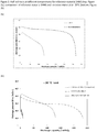
- the treated/improved hydrogen storage alloy of the present invention has significantly improved electrochemical properties, in particular capacity, at low temperatures, such as -20 °C.
- cells fabricated with unmodified powder show no activity at all at this operating temperature.
- the capacity at -20°C is superior to that of HAK treated material, as derivable from Figure 2 . While the reason for this is not fully clear, and without wishing to be bound by theory, it is believed this is maybe a consequence of the increased presence of magnetic Ni-nanoparticles/clusters adjacent to the non-oxidized alloy. Nanoparticles may require lower activation energy to initiate catalytic reactions, which could explain an enhanced activity at lower temperatures.
- a conventional material (here: HAK-treated Alloy 1, as referred to in Example 1) shows good behavior at room temperature.
- the potential shows a plateau up to a discharge capacity of almost 300 mAh/g at a current of 300 mA/g, i.e. until the material is almost fully discharged.
- This shows that a battery including a conventional HAK material will not be able to operate stably (i.e. with a plateau of the discharge potential over a substantial part of the discharge) at low temperatures, and the capacity will only be around 40 - 50 % of the capacity at room temperature.
- the hydrogen storage alloy of the present invention shows more of a plateau at low temperature of -20°C, and also keeps this plateau up to a discharge capacity of about 180 - 200 mAh/g at a current of 300 mA/g.
- the potential drops to low values only at a discharge capacity of more than 200 mAh/g, where the conventional HAK alloy only achieves around 130 mAh/g.
- the hydrogen storage alloy of the present invention thus can exhibit a capacity of 150 mAh/g (and up to 230 mAh/g) at a temperature of -20°C and a current of 300 mA/g, which is unheard of for existing hydrogen storage alloys. Notably, a non-treated hydrogen storage alloy shows almost no capacity at such low temperatures.
- a NiMH battery including an anode made from the hydrogen storage alloy of the present invention thus, has a far greater capacity at low temperatures as compared to a battery having a non-modified or HAK-treated hydrogen storage alloy anode, and exhibits much better operation properties in view of the relatively stable potential over the course of discharge.
- the discharge capacity at -20°C is about 230 mAh/g at a current of 300 mA/g in Figure 2b , which corresponds to about 70% of the capacity at room temperature.
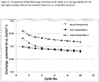
- the hydrogen storage alloy of the present invention furthermore shows a high capacity for more cycles and a longer time, which increases the lifetime of the battery.
- This is illustrated in Figure 3 , where a comparison of the discharge potentials between an untreated hydrogen storage alloy (Alloy 2 as defined below in Example 2), the respective HAK-treated material and an hydrogen peroxide treated hydrogen storage alloy according to the present invention are shown.
- the H 2 O 2 treated alloy according to the present invention shows improved cycle stability and thus has a longer lifetime.
- the surface modification by H 2 O 2 provides a more stable oxide layer that prevents further (or excessive) corrosion during cycling.
- the favorable oxide layer may inhibit an increase of the internal resistance.
- High resistance may cause polarization, which increases the parasitic reactions and energy loss in the cell, which in turn limits the battery performance.
- the parasitic reactions include electrode material corrosion and water splitting (consumes water and depletes electrolyte), which are detrimental for the lifetime of the cell and battery.
- a higher discharge potential is an indication of lower polarization losses that in turn can improve the overall lifetime performance.
- the hydrogen storage alloy of the present invention shows a higher initial discharge capacity as compared to the untreated hydrogen storage alloy, thereby also allowing a quicker and more cost-effective manufacture of a battery.
- An additional advantage is that the hydrogen storage alloy of the present invention can also be discharged (and charged) quicker than conventional materials, and is thus very suitable for application having a high demand of power, such as electric vehicles, power tools, etc.
- An additional advantage of the hydrogen storage alloy of the present invention is that it is stable in air and can be handled without the risk of pyrophoric burns. Without wishing to be bound by theory, it is believed that this effect is caused by the thicker oxide/hydroxide layer. This represents an advantage over HAK treated alloys, which are associated with the risk of pyrophoric burns and are thus more difficult to handle.
- the hydrogen storage alloy of the present invention is preferably obtained by the method for treating a hydrogen storage alloy powder for a negative electrode of a rechargeable NiMH battery of the present invention. Yet, the hydrogen storage alloy of the present invention is not limited to that obtained by the process, as long as it has a discharge capacity of 150 mAh/g or more at -20°C and a current of 300 mA/g, e.g. under the conditions employed in the Examples.
- the present invention further relates to a NiMH battery cell having an electrode made from a composition comprising a hydrogen storage alloy of the present invention, which is typically obtainable by performing the method of the present invention.
- the hydrogen storage alloy of the present invention allows realizing very high discharge capacities at high discharge currents. Due to these unique properties of the hydrogen storage alloy of the present invention, the battery cell of the present invention can exhibit a discharge capacity of 290 mAh/g of alloy or higher at a discharge current of 600 mA/g. This distinguishes the battery cell from those of the prior art, as obtained e.g. by employing a battery cell having an electrode made from a material that was subjected to the HAK treatment.
- the n/p ratio (wherein n denotes the capacity of the negative electrode and p denotes the capacity of the positive electrode) of the battery cell is preferably 1.05 - 2.2, further preferably 1.4 - 2.2, and more preferably 1.8 - 2.2, as such a ratio is considered to be beneficial for high discharge currents.
- the present invention further relates to a battery comprising one or more battery cells of the present invention, as described above.
- An AB 5 type alloy La 18 Ce 10 Pr 1 Nd 3 Al 2 Mn 5 Co 10 Ni 51 was supplied by Santuko (herein referred to as "Alloy 1").
- the indices refer to weight percent.
- the alloy powder placed in a Zirconia (YSZ) tube contained in a stainless steel autoclave was flushed by hydrogen under room temperature a few times to remove air.
- the alloy powder was then heated under 50 bar hydrogen pressure to 180 °C and kept at this temperature for 20 minutes, thereafter the hydrogen pressure was released to ambient pressure. Then the hydrogen pressure was increased to 50 bars again to hydride the alloy powder for 20 minutes. This procedure was repeated 10 times to achieve a fully decrepitated and hydrided alloy powder (step A).
- step C Parts of the alloy powder was then washed (step C) by 30% hydrogen peroxide for 30 seconds (A1), 15% hydrogen peroxide for 30 seconds (A2) and 7.5% hydrogen peroxide for 30 seconds (A3), respectively. Thereafter each powder was washed with deionized water and dried in vacuum.
- the electrochemical properties of treated alloy were measured in a half-cell test with a Lanhe CT2001A (Land) battery testing instrument.
- the working electrodes were made by mixing 0.25 g of the respective H 2 O 2 -treated alloys A1, A2 and A3, respectively, as prepared in Example 1, and 0.75 g nickel powder.
- the comparative working electrode was made by mixing 0.25g of Alloy 1 without any treatment.
- the mixture was compacted in a pressing tool with 1 cm diameter to a pellet at a pressure of 280 MPa.
- the pellet was then wrapped in a nickel net (100 mesh) and pressed again at 70 MPa. Thereafter a nickel wire was spot welded to the net for electrical connection.
- the counter electrode for the half-cell was a 20-mesh nickel net, which was also spot welded to a nickel wire for electrical connection.
- a 6 M potassium hydroxide solution was used electrolyte.
- a 3 mm zinc rod was used as reference electrode.
- a 60 mA/g charging current was applied.
- the method of the present invention allows significantly increasing the discharge capacity, in particular at discharge currents of 600 mA/g or more, such as 1200 mA/g or 2400 mA/g.
- discharge currents 600 mA/g or more, such as 1200 mA/g or 2400 mA/g.
- the method of the present invention respectively the hydrogen storage alloy powder of the present invention, is particular useful for applications in which large discharge currents occur, such as in electric vehicles, hybrid vehicles or in stationary storage for e.g. renewable energies (e.g. wind or solar power).
- the alloy powder was treated in the same manner as described in Example 1. Again, different parts of the alloy powder were then washed with 30% hydrogen peroxide for 30 seconds (A4), 15% hydrogen peroxide for 30 seconds (A5) and 7.5% hydrogen peroxide for 30 seconds (A6), respectively. After that the powder was washed with deionized water and dried in vacuum.
Landscapes
- Chemical & Material Sciences (AREA)
- Chemical Kinetics & Catalysis (AREA)
- Electrochemistry (AREA)
- General Chemical & Material Sciences (AREA)
- Engineering & Computer Science (AREA)
- Manufacturing & Machinery (AREA)
- Materials Engineering (AREA)
- Mechanical Engineering (AREA)
- Metallurgy (AREA)
- Organic Chemistry (AREA)
- Battery Electrode And Active Subsutance (AREA)
- Powder Metallurgy (AREA)
Priority Applications (2)
| Application Number | Priority Date | Filing Date | Title |
|---|---|---|---|
| EP18196021.2A EP3626845A1 (fr) | 2018-09-21 | 2018-09-21 | Poudre d'alliage d'hydrure métallique pour batteries nimh ayant des propriétés améliorées, son procédé de préparation et batterie nimh ayant des propriétés améliorées comprenant de la poudre d'alliage d'hydrure métallique |
| PCT/EP2019/075208 WO2020058423A1 (fr) | 2018-09-21 | 2019-09-19 | Poudre d'alliage d'hydrure métallique pour batteries nimh ayant des propriétés améliorées, son procédé de préparation et batterie nimh à propriétés améliorées comprenant la poudre d'alliage d'hydrure métallique |
Applications Claiming Priority (1)
| Application Number | Priority Date | Filing Date | Title |
|---|---|---|---|
| EP18196021.2A EP3626845A1 (fr) | 2018-09-21 | 2018-09-21 | Poudre d'alliage d'hydrure métallique pour batteries nimh ayant des propriétés améliorées, son procédé de préparation et batterie nimh ayant des propriétés améliorées comprenant de la poudre d'alliage d'hydrure métallique |
Publications (1)
| Publication Number | Publication Date |
|---|---|
| EP3626845A1 true EP3626845A1 (fr) | 2020-03-25 |
Family
ID=63798781
Family Applications (1)
| Application Number | Title | Priority Date | Filing Date |
|---|---|---|---|
| EP18196021.2A Withdrawn EP3626845A1 (fr) | 2018-09-21 | 2018-09-21 | Poudre d'alliage d'hydrure métallique pour batteries nimh ayant des propriétés améliorées, son procédé de préparation et batterie nimh ayant des propriétés améliorées comprenant de la poudre d'alliage d'hydrure métallique |
Country Status (2)
| Country | Link |
|---|---|
| EP (1) | EP3626845A1 (fr) |
| WO (1) | WO2020058423A1 (fr) |
Citations (6)
| Publication number | Priority date | Publication date | Assignee | Title |
|---|---|---|---|---|
| US4716088A (en) | 1986-12-29 | 1987-12-29 | Energy Conversion Devices, Inc. | Activated rechargeable hydrogen storage electrode and method |
| WO2001089009A1 (fr) | 2000-05-17 | 2001-11-22 | Höganäs Ab | Procede visant a ameliorer les proprietes de poudres d'alliage pour accumulateurs nimh |
| US20010054458A1 (en) * | 1998-02-19 | 2001-12-27 | Susumu Kikuyama | Hydrogen-absorbing alloy for battery, method for producing the same, and alkaline storage battery using the same |
| EP1219368A2 (fr) * | 2000-12-27 | 2002-07-03 | Matsushita Electric Industrial Co., Ltd. | Poudre alliée pour électrode et son procédé de production |
| US20060166099A1 (en) * | 2003-01-20 | 2006-07-27 | Kazuya Okabe | Closed nickel-hydrogen storage battery and its production method |
| US20130042466A1 (en) * | 2010-01-06 | 2013-02-21 | Shida Battery Technology Co., LTD. | Method for improving the properties of NiMH batteries |
-
2018
- 2018-09-21 EP EP18196021.2A patent/EP3626845A1/fr not_active Withdrawn
-
2019
- 2019-09-19 WO PCT/EP2019/075208 patent/WO2020058423A1/fr not_active Ceased
Patent Citations (6)
| Publication number | Priority date | Publication date | Assignee | Title |
|---|---|---|---|---|
| US4716088A (en) | 1986-12-29 | 1987-12-29 | Energy Conversion Devices, Inc. | Activated rechargeable hydrogen storage electrode and method |
| US20010054458A1 (en) * | 1998-02-19 | 2001-12-27 | Susumu Kikuyama | Hydrogen-absorbing alloy for battery, method for producing the same, and alkaline storage battery using the same |
| WO2001089009A1 (fr) | 2000-05-17 | 2001-11-22 | Höganäs Ab | Procede visant a ameliorer les proprietes de poudres d'alliage pour accumulateurs nimh |
| EP1219368A2 (fr) * | 2000-12-27 | 2002-07-03 | Matsushita Electric Industrial Co., Ltd. | Poudre alliée pour électrode et son procédé de production |
| US20060166099A1 (en) * | 2003-01-20 | 2006-07-27 | Kazuya Okabe | Closed nickel-hydrogen storage battery and its production method |
| US20130042466A1 (en) * | 2010-01-06 | 2013-02-21 | Shida Battery Technology Co., LTD. | Method for improving the properties of NiMH batteries |
Non-Patent Citations (7)
| Title |
|---|
| "Battery Technology Handbook", 2003, EXPERT VERLAG GMBH |
| D.R. BAER; M.H. ENGELHARD; A.S. LEA; P. NACHIMUTHU; T.C. DROUBAY; J. KIM; B. LEE; C. MATHEWS; R.L. OPILA; L.V. SARAF, J. VAC.SCI. TECHNOL. A, vol. 28, 2010, pages 1060 - 1072 |
| DUNLAP ET AL., J. OF THE LESS COMMON METALS, vol. 91, 1983, pages 1 - 20 |
| J. POWER SOURCES, vol. 398, 2018, pages 42 - 48 |
| K. YOUNG ET AL., INT. J. HYDROGEN ENERGY, vol. 37, no. 12, 2012, pages 9882 - 9891 |
| WANG ET AL., CHEM. ENG. J., vol. 352, 2018, pages 325 - 332 |
| YOUNG K ET AL: "Effects of HOaddition to the cell balance and self-discharge of Ni/MH batteries with ABand ABalloys", INTERNATIONAL JOURNAL OF HYDROGEN ENERGY, ELSEVIER SCIENCE PUBLISHERS B.V., BARKING, GB, vol. 37, no. 12, 22 March 2012 (2012-03-22), pages 9882 - 9891, XP028487477, ISSN: 0360-3199, [retrieved on 20120328], DOI: 10.1016/J.IJHYDENE.2012.03.117 * |
Also Published As
| Publication number | Publication date |
|---|---|
| WO2020058423A1 (fr) | 2020-03-26 |
Similar Documents
| Publication | Publication Date | Title |
|---|---|---|
| JP2799389B2 (ja) | 充電維持強化電気化学的水素吸蔵合金及び充電維持強化電気化学的セル | |
| US4923770A (en) | Amorphous metal alloy compositions for reversible hydrogen storage and electrodes made therefrom | |
| EP1164650B1 (fr) | Batterie rechargeable au nickel et procédé pour sa production | |
| KR960013373B1 (ko) | 활성화된 재충전가능 수소축전전극 및 그 제조방법 | |
| EP2128914A1 (fr) | Matériau d'électrode négative pour une batterie nickel-hydrogène, procédé de traitement de celui-ci, et batterie nickel-hydrogène | |
| US5034289A (en) | Alkaline storage battery and method of producing negative electrode thereof | |
| EP0696823A1 (fr) | Electrode absorbant l'hydrogene et son procede de production | |
| JP2012188728A (ja) | 複合水素吸蔵合金及びニッケル水素蓄電池 | |
| Cui et al. | Synthesis and electrode characteristics of the new composite alloys Mg2Ni-xwt.% Ti2Ni | |
| Choi et al. | Effects of Surface Treatment with Boiling Alkaline Solution on Electrochemical and Physicochemical Properties of the Zr0. 9Ti0. 1Ni1. 1Co0. 1Mn0. 6 V 0.2 Alloy Electrode | |
| JP2010007177A (ja) | 水素吸蔵合金粉末とその表面処理方法、アルカリ蓄電池用負極、およびアルカリ蓄電池 | |
| Fiorino et al. | Electrochemical and X‐Ray Photoelectron Spectroscopy Characterization of Surface Films on MmNi3. 5Al0. 8Co0. 7 | |
| RU2671942C1 (ru) | Анодный материал и батарея | |
| EP2487270B1 (fr) | Matière active pour électrode négative d'accumulateur alcalin de type nickel hydrure métallique | |
| JP5148553B2 (ja) | 電極用複合材料およびその製造法、ならびにそれを用いるアルカリ蓄電池 | |
| EP3626845A1 (fr) | Poudre d'alliage d'hydrure métallique pour batteries nimh ayant des propriétés améliorées, son procédé de préparation et batterie nimh ayant des propriétés améliorées comprenant de la poudre d'alliage d'hydrure métallique | |
| KR940007634B1 (ko) | 알카리 분위기에서 사용하기 위한 비결정성 금속 합금 전극과 에너지 저장 장치 | |
| Gao et al. | Electrochemical and surface properties of the Zr (V0. 2Mn0. 2Ni0. 6) 2.4 alloy electrode | |
| JPH0963581A (ja) | 水素吸蔵合金粉末の表面処理方法とそれを適用して得られたアルカリ二次電池 | |
| JPH09180715A (ja) | 水素吸蔵合金の水蒸気による表面処理方法と得られた合金 | |
| JP2003077468A (ja) | ニッケル電極材料の製造方法 | |
| Lee et al. | Study on the electrode characteristics of hypostoichiometric Zr‐Ti‐V‐Mn‐Ni hydrogen storage alloys | |
| JPH1150263A (ja) | 安定化水素吸蔵合金の製造方法 | |
| JPH0810596B2 (ja) | 金属酸化物・水素電池 | |
| JP2001266860A (ja) | ニッケル−水素蓄電池 |
Legal Events
| Date | Code | Title | Description |
|---|---|---|---|
| PUAI | Public reference made under article 153(3) epc to a published international application that has entered the european phase |
Free format text: ORIGINAL CODE: 0009012 |
|
| STAA | Information on the status of an ep patent application or granted ep patent |
Free format text: STATUS: THE APPLICATION HAS BEEN WITHDRAWN |
|
| AK | Designated contracting states |
Kind code of ref document: A1 Designated state(s): AL AT BE BG CH CY CZ DE DK EE ES FI FR GB GR HR HU IE IS IT LI LT LU LV MC MK MT NL NO PL PT RO RS SE SI SK SM TR |
|
| AX | Request for extension of the european patent |
Extension state: BA ME |
|
| 18W | Application withdrawn |
Effective date: 20200227 |