EP3627087A1 - Échangeur de chaleur de type à plaques - Google Patents
Échangeur de chaleur de type à plaques Download PDFInfo
- Publication number
- EP3627087A1 EP3627087A1 EP17911106.7A EP17911106A EP3627087A1 EP 3627087 A1 EP3627087 A1 EP 3627087A1 EP 17911106 A EP17911106 A EP 17911106A EP 3627087 A1 EP3627087 A1 EP 3627087A1
- Authority
- EP
- European Patent Office
- Prior art keywords
- heat transfer
- ridges
- adjacent
- valleys
- transfer plates
- Prior art date
- Legal status (The legal status is an assumption and is not a legal conclusion. Google has not performed a legal analysis and makes no representation as to the accuracy of the status listed.)
- Granted
Links
Images













Classifications
-
- F—MECHANICAL ENGINEERING; LIGHTING; HEATING; WEAPONS; BLASTING
- F28—HEAT EXCHANGE IN GENERAL
- F28D—HEAT-EXCHANGE APPARATUS, NOT PROVIDED FOR IN ANOTHER SUBCLASS, IN WHICH THE HEAT-EXCHANGE MEDIA DO NOT COME INTO DIRECT CONTACT
- F28D9/00—Heat-exchange apparatus having stationary plate-like or laminated conduit assemblies for both heat-exchange media, the media being in contact with different sides of a conduit wall
- F28D9/0031—Heat-exchange apparatus having stationary plate-like or laminated conduit assemblies for both heat-exchange media, the media being in contact with different sides of a conduit wall the conduits for one heat-exchange medium being formed by paired plates touching each other
- F28D9/0043—Heat-exchange apparatus having stationary plate-like or laminated conduit assemblies for both heat-exchange media, the media being in contact with different sides of a conduit wall the conduits for one heat-exchange medium being formed by paired plates touching each other the plates having openings therein for circulation of at least one heat-exchange medium from one conduit to another
- F28D9/005—Heat-exchange apparatus having stationary plate-like or laminated conduit assemblies for both heat-exchange media, the media being in contact with different sides of a conduit wall the conduits for one heat-exchange medium being formed by paired plates touching each other the plates having openings therein for circulation of at least one heat-exchange medium from one conduit to another the plates having openings therein for both heat-exchange media
-
- F—MECHANICAL ENGINEERING; LIGHTING; HEATING; WEAPONS; BLASTING
- F28—HEAT EXCHANGE IN GENERAL
- F28D—HEAT-EXCHANGE APPARATUS, NOT PROVIDED FOR IN ANOTHER SUBCLASS, IN WHICH THE HEAT-EXCHANGE MEDIA DO NOT COME INTO DIRECT CONTACT
- F28D9/00—Heat-exchange apparatus having stationary plate-like or laminated conduit assemblies for both heat-exchange media, the media being in contact with different sides of a conduit wall
- F28D9/02—Heat-exchange apparatus having stationary plate-like or laminated conduit assemblies for both heat-exchange media, the media being in contact with different sides of a conduit wall the heat-exchange media travelling at an angle to one another
-
- F—MECHANICAL ENGINEERING; LIGHTING; HEATING; WEAPONS; BLASTING
- F28—HEAT EXCHANGE IN GENERAL
- F28F—DETAILS OF HEAT-EXCHANGE AND HEAT-TRANSFER APPARATUS, OF GENERAL APPLICATION
- F28F3/00—Plate-like or laminated elements; Assemblies of plate-like or laminated elements
- F28F3/02—Elements or assemblies thereof with means for increasing heat-transfer area, e.g. with fins, with recesses, with corrugations
- F28F3/04—Elements or assemblies thereof with means for increasing heat-transfer area, e.g. with fins, with recesses, with corrugations the means being integral with the element
-
- F—MECHANICAL ENGINEERING; LIGHTING; HEATING; WEAPONS; BLASTING
- F28—HEAT EXCHANGE IN GENERAL
- F28F—DETAILS OF HEAT-EXCHANGE AND HEAT-TRANSFER APPARATUS, OF GENERAL APPLICATION
- F28F3/00—Plate-like or laminated elements; Assemblies of plate-like or laminated elements
- F28F3/02—Elements or assemblies thereof with means for increasing heat-transfer area, e.g. with fins, with recesses, with corrugations
- F28F3/04—Elements or assemblies thereof with means for increasing heat-transfer area, e.g. with fins, with recesses, with corrugations the means being integral with the element
- F28F3/042—Elements or assemblies thereof with means for increasing heat-transfer area, e.g. with fins, with recesses, with corrugations the means being integral with the element in the form of local deformations of the element
- F28F3/046—Elements or assemblies thereof with means for increasing heat-transfer area, e.g. with fins, with recesses, with corrugations the means being integral with the element in the form of local deformations of the element the deformations being linear, e.g. corrugations
Definitions
- the present invention relates to a plate heat exchanger used as a condenser and an evaporator.
- the plate heat exchanger includes a plurality of heat transfer plates.
- Each of the plurality of heat transfer plates includes a heat transfer portion.
- the heat transfer portion has a first surface and a second surface in a first direction.
- the heat transfer portion has the first surface on which ridges and valleys are formed, and the second surface that faces an opposite side to the first surface and on which valleys each serving as the back of each corresponding one of the ridges on the first surface and ridges located on the back of the respective valleys on the first surface are formed.
- the ridges intersect with a centerline (hereinafter referred to as vertical centerline) of the heat transfer portion extending in a second direction orthogonal to the first direction.
- the ridges are formed over the entire length of the heat transfer portion in a third direction orthogonal to both the first direction and the second direction.
- the plurality of heat transfer plates are stacked on each other in the first direction. That is, each of the plurality of heat transfer plates has the first surface of its heat transfer portion opposed to the first surface of the heat transfer portion of each adjacent heat transfer plate aligned on one side of the first direction. Each of the plurality of heat transfer plates has the second surface of its heat transfer portion opposed to the second surface of the heat transfer portion of the adjacent heat transfer plate aligned on the other side of the first direction.
- a first flow channel for circulating a first fluid medium in the second direction is formed between the first surfaces of the heat transfer portions of each two adjacent heat transfer plates.
- a second flow channel for circulating a second fluid medium in the second direction is formed between the second surfaces of the heat transfer portions of each two adjacent heat transfer plates.
- the plate heat exchanger of this type is used as a condenser that is configured to condense the second fluid medium within the second flow channels through the heat exchange between the first fluid medium within the first flow channels and the second fluid medium within the second flow channels.
- the plate heat exchanger of this type is used as an evaporator that is configured to evaporate the second fluid medium within the second flow channels through the heat exchange between the first fluid medium within the first flow channels and the second fluid medium within the second flow channels.
- the conventional plate heat exchanger when used as the condenser or the evaporator, has a limit in improving heat exchange performance due to the characteristics of the second fluid medium, which is subjected to condensation or evaporation.
- the ridges on each of the heat transfer portions are formed crossing the vertical centerline of the heat transfer portion and extending over the entire length of the heat transfer portion in the third direction. This configuration causes the ridges of the heat transfer portion to increase circulating resistance of both the first flow channels and the second flow channels.
- a fluid medium that does not cause phase change (a fluid medium having single-phase flow) is employed as the first fluid medium. Therefore, increase in the circulating resistance in the first flow channels causes the heat transfer portions to be more likely to be subjected to thermal influences. The increase in the circulating resistance in the first flow channels consequently becomes a factor for improved heat exchange performance.
- a fluid medium that causes phase change (a fluid medium having two-phase flow that contains liquid and gas), such as fluorocarbons, is employed as the second fluid medium.
- a fluid medium having two-phase flow that contains liquid and gas such as fluorocarbons
- the ridges on each of the heat transfer portions are formed crossing the vertical centerline of the heat transfer portion and extending over the entire length in the third direction of the heat transfer portion, the ridges on the heat transfer portions block flow of the second fluid medium within the second flow channels. That is, the ridges on the second surfaces of the heat transfer portions are formed to cross (intersect with) the flow of the second fluid medium within the second flow channels, and thereby increase the circulating resistance of the second fluid medium within the second flow channels.
- the conventional plate heat exchanger has a limit in increasing the velocity of the second fluid medium within the second flow channels, and thus cannot sufficiently disturb the flow of the liquid film of the second fluid medium formed on the second surfaces of the heat transfer portions.
- the conventional plate heat exchanger has a limit in improving the performance for transferring, to the heat transfer portion, heat of the second fluid medium that is circulated through the second flow channels.
- Patent Literature 1 JP 2001-99588 A
- a plate heat exchanger of the present invention includes a plurality of heat transfer plates each including a heat transfer portion having a first surface on which ridges and valleys are formed, and a second surface that is opposed to the first surface and on which valleys being in a front-back relationship with the ridges of the first surface and ridges being in a front-back relationship with the valleys of the first surface are formed, the plurality of heat transfer plates respectively having the heat transfer portions stacked on each other in a first direction, wherein the first surface of the heat transfer portion of each of the plurality of heat transfer plates is arranged opposed to the first surface of the heat transfer portion of one of the plurality of heat transfer plates adjacent to the each heat transfer plate on one side in the first direction, and the second surface of the heat transfer portion of each of the plurality of heat transfer plates is arranged opposed to the second surface of the heat transfer portion of one of the plurality of heat transfer plates adjacent to the each heat transfer plate on an other side in the first direction, wherein a first flow channel through which a first fluid medium is circul
- the at least one of each adjacent two of the plurality of heat transfer plates include, as the ridges formed on the first surface, a plurality of barrier ridges arranged at intervals from each other in the second direction.
- each of the heat transfer portions of each adjacent two of the plurality of heat transfer plates includes, as the ridges formed on the second surface, a plurality of second ridges being in a front-back relationship with the plurality of first valleys, and that the plurality of second ridges of one of each adjacent two of the plurality of heat transfer plates are overlapped with the plurality of second ridges of the opposed heat transfer plate and are in contact with top ends of the plurality of second ridges of the opposed heat transfer plate.
- the configuration may be such that the at least one barrier ridge includes at least one bent ridge portion, and that the at least one bent ridge portion includes a pair of inclined ridge portions each having a proximal end and a distal end on an opposite side of the proximal end, the pair of inclined ridge portions being inclined in directions opposite to each other relative to a centerline extending in the second direction or a virtual line parallel to the centerline, and having the distal ends thereof connected to each other.
- each of the heat transfer portions of each adjacent two of the plurality of heat transfer plates include the at least one barrier ridge including the at least one bent ridge portion, and that the at least one bent ridge portion of the at least one barrier ridge of one of each adjacent two of the plurality of heat transfer plates be bent in a direction completely opposite to that of the at least one bent ridge portion of the opposed heat transfer plate.
- a plate heat exchanger 1 according to the first embodiment includes three or more heat transfer plates 2, 3.
- the three or more heat transfer plates 2, 3 are stacked on each other in a first direction.
- the three or more heat transfer plates 2, 3 are composed of two kinds of heat transfer plates.
- the two kinds of heat transfer plates 2, 3 are arranged alternately in the first direction.
- first flow channels Ra through which a first fluid medium A is circulated and second flow channels Rb through which a second fluid medium B is circulated are alternately formed in the first direction with the heat transfer plates 2, 3 respectively interposed therebetween, as shown in Fig. 2 .
- the two kinds of heat transfer plates 2, 3 will be specifically described.
- the two kinds of heat transfer plates 2, 3 have common features and different features. First, the common features of the two kinds of heat transfer plates 2, 3 will be described.
- the heat transfer plates 2, 3 respectively include heat transfer portions 20, 30 that respectively have first surfaces Sa1, Sb1 and second surfaces Sa2, Sb2 facing opposite to the first surfaces Sa1, Sb1, and annular fitting portions 21, 31 that respectively extend from the entire outer peripheral edges of the heat transfer portions 20, 30 while having surfaces extending in a direction intersecting with the surfaces of the heat transfer portions 20, 30.
- the heat transfer portions 20, 30 have a thickness in the first direction. Accordingly, the first surfaces Sa1, Sb1 and the second surfaces Sa2, Sb2 of the heat transfer portions 20, 30 are aligned in the first direction.
- the heat transfer portions 20, 30 have an external form (contour) defined by a pair of long sides extending in a second direction orthogonal to the first direction, and a pair of short sides arranged with a distance from each other in the second direction while extending in a third direction orthogonal to the first direction and the second direction to connect the pair of long sides. That is, the heat transfer portions 20, 30 have an external form having a rectangular shape with the long sides extending in the second direction, when seen from the first direction.
- Each of the heat transfer portions 20, 30 has one end and the other end on the opposite side to the one end in the second direction.
- the heat transfer portions 20, 30 respectively have at least two openings 200, 201, 202, 203, 300, 301, 302, 303 in each of the one ends and the other ends in the second direction.
- the heat transfer portions 20, 30 respectively have two openings 200, 203, 300, 303 in the one ends in the second direction, and two openings 201, 202, 301, 302 in the other ends in the second direction.
- the two openings 200, 203, 300, 303 in the one ends in the second direction of the heat transfer portions 20, 30 are aligned in the third direction.
- the two openings 201, 202, 301, 302 in the other ends in the second direction of the heat transfer portions 20, 30 are aligned in the third direction.
- An area surrounding each of the one openings 200, 300 in the one ends and an area surrounding each of the one openings 201, 301 in the other ends in the second direction of the heat transfer portions 20, 30 are recessed on the first surfaces Sa1, Sb1 side. Accordingly, an area surrounding each of the one openings 200, 300 in the one ends and an area surrounding each of the one openings 201, 301 in the other ends in the second direction of the heat transfer portions 20, 30 are projected on the second surfaces Sa2, Sb2 side.
- the projected amounts on the second surfaces Sa2, Sb2 sides of the area surrounding each of the one openings 200, 300 and the area surrounding each of the one openings 201, 301 in the other ends in the one ends in the second direction of the heat transfer portions 20, 30 are set so that these areas can respectively contact the corresponding areas respectively surrounding the openings 200, 201, 300, 301 (i.e., the one openings 200, 300 in the one ends and the one openings 201, 301 in the other ends) of the heat transfer portions 20, 30 of each two adjacent heat transfer plates 2, 3 aligned with each other in the first direction.
- an area surrounding each of the other openings 203, 303 in the one ends and an area surrounding each of the other openings 202, 302 in the other ends in the second direction of the heat transfer portions 20, 30 are recessed on the second surfaces Sa2, Sb2 side. Accordingly, an area surrounding each of the other openings 203, 303 in the one ends and an area surrounding each of the other openings 202, 302 in the other ends in the second direction of the heat transfer portions 20, 30 are projected on the first surfaces Sa1, Sb1 side.
- the projected amounts on the first surfaces Sa1, Sb1 sides of the area surrounding each of the other openings 203, 303 in the one ends and the area surrounding each of the other openings 202, 302 in the other ends in the second direction of the heat transfer portions 20, 30 are set so that these areas can respectively contact the corresponding areas respectively surrounding the openings 202, 203, 302, 303 (i.e., the other openings 202, 302 in the one ends and the other openings 203, 303 in the other ends) of the heat transfer portions 20, 30 of each two adjacent heat transfer plates 2, 3 aligned with each other in the first direction.
- recessed areas out of the areas each surrounding the openings 200, 201, 202, 203, 300, 301, 302, 303, and bottom parts of valleys 22, 32, which will be described later, are shown in stippling to allow the relationship between the projected portions and the recessed portions of the first surfaces Sa1, Sb1 and the second surfaces Sa2, Sb2 to be distinguishable.
- the one openings 200, 300 in the one ends and the one openings 201, 301 in the other ends in the second direction of the heat transfer portions 20, 30 are located diagonal to each other, due to the configuration in which the heat transfer plates 2, 3 are stacked on each other.
- the other openings 203, 303 in the one ends and the other openings 202, 302 in the other ends in the second direction of the heat transfer portions 20, 30 are also located diagonal to each other.
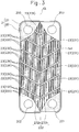
- the valleys 22, 32 and ridges 23, 33 are respectively formed on each of the first surfaces Sa1, Sb1 and the second surfaces Sa2, Sb2 of the heat transfer portions 20, 30.
- Each of the first surfaces Sa1, Sb1 and the second surfaces Sa2, Sb2 of the heat transfer portions 20, 30 has a plurality (a large number) of valleys 22, 32 and a plurality (a large number) of ridges 23, 33.
- each of the heat transfer plates 2, 3 is formed by press molding of a metal plate. Accordingly, the valleys 22, 32 formed on the first surfaces Sa1, Sb1 of the heat transfer portions 20, 30 are in a front-back relationship with the ridges 23, 33 formed on the second surfaces Sa2, Sb2 of the heat transfer portions 20, 30. The ridges 23, 33 formed on the first surfaces Sa1, Sb1 of the heat transfer portions 20, 30 are in a front-back relationship with the valleys 22, 32 formed on the second surfaces Sa2, Sb2 of the heat transfer portions 20, 30.
- the deformation of the metal plate by press molding allows the valleys 22, 32 formed on the first surfaces Sa1, Sb1 of the heat transfer portions 20, 30 to be formed at positions corresponding to the positions of the ridges 23, 33 formed on the second surfaces Sa2, Sb2 of the heat transfer portions 20, 30. Also, the deformation of the metal plate by press molding allows the ridges 23, 33 formed on the first surfaces Sa1, Sb1 of the heat transfer portions 20, 30 to be formed at positions corresponding to the positions of the valleys 22, 32 formed on the second surfaces Sa2, Sb2 of the heat transfer portions 20, 30.
- the heat transfer portion 20, 30 includes, as the valleys 22, 32 formed on the first surface Sa1, Sb1, a plurality of first valleys 220, 320 extending in the second direction and arranged at intervals from each other in the third direction.
- the heat transfer portion 20, 30 includes, as the ridges 23, 33 formed on the first surface Sa1, Sb1, a plurality of first ridges 230, 330 each extending in the second direction between each two first valleys 220, 230 adjacent to each other in the third direction. That is, in the first surface Sa1, Sb1 of the heat transfer portion 20, 30, the first valleys 220, 320 and the first ridges 230, 330 are alternately arranged in the third direction.
- the heat transfer portion 20, 30 includes, as the ridges 23, 33 formed on the first surface Sa1, Sb1, at least one barrier ridge 231, 331 that is lower than the first ridges 230, 330 formed on the first surface Sa1, Sb1, the at least one barrier ridge 231, 331 extending in a direction intersecting with the plurality of first ridges 230, 330.
- Each of the plurality of first valleys 220, 320 has the same or substantially the same width in the third direction as each of the plurality of first ridges 230, 330.
- the internal surfaces defining the first valleys 220, 320 are continuous with the external surfaces defining the first ridges 230, 330.
- the first surface Sa1, Sb1 of the heat transfer portion 20, 30 has a corrugated shape with projections and recesses aligned in the first direction.
- the boundary between a specific first valley 220, 320 out of the plurality of first valleys 220, 320 and a specific first ridge 230, 330 out of the plurality of first ridges 230, 330 that is adjacent to the specific first valley 220, 320 is located on the vertical centerline CL of the first surface Sa1, Sb1 of the heat transfer portion 20, 30.
- the specific first valley 220, 320 or the specific first ridge 230, 330 is arranged while being displaced in the third direction from the vertical centerline CL by one-fourth of the distance between adjacent first ridges 230, 330 with one first valley 220, 320 interposed therebetween, or the distance between each two adjacent first valleys 220, 320 with one first ridge 230, 330 interposed therebetween.
- the first surface Sa1,Sb1 of the heat transfer portion 20, 30 has a plurality of barrier ridges 231, 331.
- the plurality of barrier ridges 231, 331 are arranged at intervals from each other in the second direction.
- Each of the plurality of barrier ridges 231, 331 is lower than the first ridges 230, 330 as aforementioned.
- the projected amount of the barrier ridges 231, 331 from a virtual plane (the virtual plane extending in the second direction and the third direction) passing through top ends of a plurality of second ridges 233, 333, which will be described later, formed on the second surface Sa2, Sb2 is smaller than that of the first ridges 230, 330.
- the top ends of the barrier ridges 231, 331 are located closer in the first direction to the second surface Sa2, Sb2 than the top ends of the first ridges 230, 330. That is, the top ends of the barrier ridges 231, 331 are located between the top ends of the first ridges 230, 330 and bottom ends of the first valleys 220, 320.
- each of the first ridges 230, 330 on one heat transfer plate 2, 3 of each adjacent heat transfer plates 2, 3 is located between each two adjacent first ridges 230, 330 (i.e., located to face a corresponding one of the first valleys 220, 320) of the other heat transfer plate 2, 3 of the each two adjacent heat transfer plates 2, 3.
- the distance in the first direction between the top ends of the first ridges 230, 330 and the top ends of the barrier ridges 231, 331 is set so that the clearance between the first ridges 230, 330 of one heat transfer plate 2, 3 out of each two adjacent heat transfer plates 2, 3 and the first valleys 220, 320 of the other heat transfer plate 2, 3 can secure circulation of the first fluid medium A.
- the plurality of first valleys 220, 320 are set to have the same width and the plurality of first ridges 230, 330 are set to have the same width.
- the first valleys 220, 320 and the first ridges 230, 330 are set to have substantially the same width.
- the distance in the first direction between the top ends of the first ridges 230, 330 and the top ends of the barrier ridges 231, 331 is set so that the clearances between the both sides in the width direction of each of the first ridges 230, 330 and the both sides in the width direction of each of the first valleys 220, 320 have a distance to secure circulation of the first fluid medium A.
- the barrier ridges 231, 331 intersect with the plurality of first ridges 230, 330 and the plurality of first valleys 220, 320.
- the barrier ridges 231, 331 are formed over the entire length in the third direction of the heat transfer portion 20, 30.
- the barrier ridges 231, 331 include at least one bent ridge portion 232, 332.
- the bent ridge portion 232, 332 includes a pair of inclined ridge portions 232a, 232b, 332a, 332b each portion having a proximal end and a distal end on the opposite side of the proximal end, the pair of inclined ridge portions 232a, 232b, 332a, 332b being inclined in a direction opposite to each other with respect to the vertical centerline CL and having the distal ends thereof connected to each other.
- the barrier ridges 231, 331 have one bent ridge portion 232, 332.
- the proximal ends of the pair of inclined ridge portions 232a, 232b, 332a, 332b that constitute the bent ridge portion 232, 332 are located on an end edge in the third direction of the heat transfer portion 20, 30.
- the distal ends of the pair of inclined ridge portions 232a, 232b, 332a, 332b are located at the center (on the vertical centerline CL) in the third direction of the heat transfer portion 20, 30.
- the distal ends of the pair of inclined ridge portions 232a, 232b, 332a, 332b are connected in face-to-face relationship.
- the pair of inclined ridge portions 232a, 232b, 332a, 332b are symmetrically arranged with reference to a virtual line that extends in the second direction. That is, the pair of inclined ridge portions 232a, 232b, 332a, 332b are inclined in a direction completely opposite to each other. However, the pair of inclined ridge portions 232a, 232b, 332a, 332b have the same inclination angle with respect to the vertical centerline CL extending in the second direction.
- the barrier ridges 231 and 331 are provided over the entire width in the third direction of the heat transfer portion 20, 30.
- the first valleys 220, 320 and the first ridges 230, 330 on the first surface Sa1,Sb1 of the heat transfer portion 20, 30 are divided at a plurality of places in the second direction. Accordingly, at least one end of each of the divided first valleys 220, 320 and at least one end of each of the divided first ridges 230, 330 are joined to a corresponding one of the barrier ridges 231, 331.
- the divided first valleys 220, 320 are aligned with each other in the second direction. Accordingly, the divided first ridges 230, 330 are also aligned with each other in the second direction.
- the heat transfer portion 20, 30 includes, as the valleys 22, 32 formed on the second surface Sa2, Sb2, a plurality of second valleys 221, 321 extending in the second direction and arranged at intervals from each other in the third direction.
- the heat transfer portion 20, 30 includes, as the ridges 23, 33 formed on the second surface Sa2, Sb2, a plurality of second ridges 233, 333 each extending in the second direction between each two second valleys 221, 231 adjacent to each other in the third direction. That is, in the second surface Sa2, Sb2 of the heat transfer portion 20, 30, the second valleys 221, 321 and the second ridges 233, 333 are alternately arranged in the third direction.
- the heat transfer portion 20, 30 includes, as the valleys 22, 32 formed on the second surface Sa2, Sb2, valleys (hereinafter referred to as back side valleys) 222, 322 formed respectively on the back sides of the barrier ridges 231, 331 on the first surface Sa1, Sb1.
- the second valleys 221, 321 are the valleys 22, 32 formed on the back sides of the first ridges 230, 330 on the first surface Sa1, Sb1. Thus, the second valleys 221, 321 extend in the second direction.
- the second ridges 233, 333 are the ridges 23, 33 formed on the back sides of the first valleys 220 and 320 on the first surface Sa1, Sb1. Thus, the second ridges 233, 333 extend in the second direction.
- the internal surfaces defining the second valleys 221, 321 are continuous with the external surfaces defining the second ridges 233, 333.
- the second surface Sa2, Sb2 of the heat transfer portion 20, 30 has a corrugated shape with projections and recesses in the first direction.
- the back side valleys 222, 322 are formed in the same pattern as the barrier ridges 231, 331 except that they have a reversed concavo-convex relationship.
- a bent valley portion 223, 323 that includes a pair of inclined valley portions 223a, 223b, 323a, 323b is formed, which is the valley 22, 32 formed on the back side of each pair of inclined ridge portions 232a, 232b, 332a, 332b.
- the bent ridge portion 232, 332 (the pair of inclined ridge portions 232a, 232b, 332a, 332b) constitutes the barrier ridge 231, 331.
- the bent valley portion 223, 323 constitutes each of the entire back side valleys 222, 322 formed on the back side of each of the barrier ridges 231, 331.
- each of the divided second ridges 233, 333 is connected to a corresponding one of the back side valleys 222, 322. That is, the divided second valleys 221, 321 are open to the inside of the back side valleys 222, 322.
- first heat transfer plate first heat transfer plate
- second heat transfer plate second heat transfer plate
- the first valleys 220, 320 and the first ridges 230, 330 are respectively arranged so that the first ridges 230 of the first heat transfer plate 2 are opposed to the first valleys 320 of the second heat transfer plate 3 and that the first ridges 330 of the second heat transfer plate 3 are opposed to the first valleys 220 of the first heat transfer plate 2.
- the barrier ridges 231 of the first heat transfer plate 2 and the barrier ridges 331 of the second heat transfer plate 3 are provided in a mutually inverted form with reference to a virtual line extending in the third direction. That is, the inclined ridge portions 232a, 232b of the barrier ridge 231 of the first heat transfer plate 2 are inclined in a direction completely opposite to that of the inclined ridge portions 332a, 332b of the barrier ridge 331 of the second heat transfer plate 3.
- each of the first heat transfer plates 2 includes the fitting portion 21 projecting on the first surface Sa1 side of the heat transfer portion 20.
- each of the second heat transfer plates 3 includes the fitting portion 31 projecting on the second surface Sb2 side of the heat transfer portion 30.
- each of the plurality of heat transfer plates 2, 3 has been described as above.
- the plurality of heat transfer plates 2, 3 (the first heat transfer plates 2 and the second heat transfer plates 3) are stacked on each other in the first direction, as shown in Fig. 2 .
- the first heat transfer plates 2 and the second heat transfer plates 3 are alternately stacked on each other in the first direction.
- each of the plurality of heat transfer plates 2, 3 has the first surface Sa1, Sb1 of its heat transfer portion 20, 30 opposed to the first surface Sa1, Sb1 of the heat transfer portion 20, 30 of the adjacent heat transfer plate 2, 3 on one side in the first direction.
- each of the plurality of heat transfer plates 2, 3 has the second surface Sa2, Sb2 of its heat transfer portion 20, 30 opposed to the second surface Sa2, Sb2 of the heat transfer portion 20, 30 of the adjacent heat transfer plate 2, 3 on the other side in the first direction.
- each of the first flow channels Ra through which the first fluid medium A is circulated in the second direction and the second flow channels Rb through which the second fluid medium B is circulated in the second direction are alternately formed with the heat transfer portions 20, 30 of the heat transfer plates 2, 3 respectively interposed therebetween. That is, each of the first flow channels Ra through which the first fluid medium A is circulated is formed between the first surfaces Sa1, Sb1 of the heat transfer portions 20, 30 of each two adjacent heat transfer plates 2, 3, and each of the second flow channels Ra through which the second fluid medium B is circulated is formed between the second surfaces Sa2, Sb2 of the heat transfer portions 20, 30 of each two adjacent heat transfer plates 2, 3.
- the openings 200, 201, 202, 203, 300, 301, 302, 303 located in the corresponding positions of the heat transfer portions 20, 30 are lined up in the first direction, as shown in Fig. 2 .
- the areas respectively surrounding the openings 200, 201, 202, 203, 300, 301, 302, 303 that are opposed to and projected toward each other contact each other.
- This configuration forms a first inflow channel Pa1 for supplying the first fluid medium A into the first flow channels Ra, a first outflow channel Pa2 for causing the first fluid medium A to flow out of the first flow channels Ra, a second inflow channel Pb 1 for supplying the second fluid medium B into the second flow channels Rb, and a second outflow channel Pb2 for causing the second fluid medium B to flow out of the second flow channels Rb.
- each of the first heat transfer plates 2 and each of the second heat transfer plates 3 are stacked on each other to form a pair with their back side valleys 222, 322 opposed to each other.
- every other pair is turned 180 degrees upside down about a virtual line extending in the first direction.
- the barrier ridges 231 are lower than the first ridges 230, and on the second heat transfer plate 3, the barrier ridges 331 are lower than the first ridges 330; thus, the barrier ridges 231 of the first heat transfer plate 2 cross and abut against the first ridges 330 of the second heat transfer plate 3, and the barrier ridges 331 of the second heat transfer plate 3 cross and abut against the first ridges 230 of the first heat transfer plate 2.
- the barrier ridges 231 of the first heat transfer plate 2 and the barrier ridges 331 of the second heat transfer plate 3 are provided in a mutually inverted form with reference to the virtual line extending in the third direction; thus, in the state of being arranged as aforementioned, the barrier ridges 231 of the first heat transfer plate 2 and the barrier ridges 331 of the second heat transfer plate 3 are arranged to intersect with each other as seen from the first direction, as shown in Fig. 11 .
- the boundary between a specific first valley 220, 320 out of the plurality of first valleys 220, 320 and a specific first ridge 230, 330 out of the plurality of first ridges 230, 330 that is adjacent to the specific first valley 220, 320 is located on the vertical centerline CL.
- turning the first heat transfer plates 2 and the second heat transfer plates 3 180° upside down as aforementioned causes the second ridges 233, 333 of each two adjacent heat transfer plates 2, 3 to be opposed to each other and causes their top ends to be in contact with each other.
- the back side valleys 222, 322 of each two adjacent heat transfer plates 2, 3 are opposed to each other (i.e., located corresponding to each other) as seen from the first direction (see Fig. 12 ).
- the first flow channel Ra through which the first fluid medium A is circulated in the second direction orthogonal to the first direction is formed between the first surfaces Sa1, Sb1 of the heat transfer portions 20, 30 of each two adjacent heat transfer plates 2, 3.
- the second flow channel Rb through which the second fluid medium B is circulated in the second direction is formed between the second surfaces Sa2, Sb2 of the heat transfer portions 20, 30 of each two adjacent heat transfer plates 2, 3.
- the plurality of heat transfer plates 2, 3 are stacked on each other in the first direction so that the openings 200, 201, 202, 203, 300, 301, 302, 303 located in the corresponding positions of the heat transfer portions 20, 30 are lined up in the first direction.
- the areas respectively surrounding the openings 200, 201, 202, 203, 300, 301, 302, 303 that are opposed to and projected toward each other contact each other.
- This configuration forms the first inflow channel Pa1 for supplying the first fluid medium A into the first flow channels Ra, the first outflow channel Pa2 for causing the first fluid medium A to flow out of the first flow channels Ra, the second inflow channel Pb 1 for supplying the second fluid medium B into the second flow channels Rb, and the second outflow channel Pb2 for causing the second fluid medium B to flow out of the second flow channels Rb.
- the contacted portions between each two adjacent heat transfer plates 2, 3 are brazed together.
- This configuration allows the plurality of heat transfer plates 2, 3 to be integrally (mechanically) connected to each other, and an interface between the opposed surfaces (contacted portions) of the adjacent heat transfer plates 2, 3 to be sealed.
- the heat exchanger 1 has been described as above.
- the first fluid medium A flows from the first inflow channel Pa1 into the plurality of first flow channels Ra.
- the first fluid medium A is circulated through each of the first flow channels Ra in the second direction, and flows out to the first outflow channel Pa2.
- the second fluid medium B flows from the second inflow channel Pb 1 into the plurality of second flow channels Rb.
- the second fluid medium B is circulated through each of the plurality of second flow channels Rb in the second direction, and flows out to the second outflow channel Pb2.
- the first fluid medium A is circulated through each of the first flow channels Ra with a diagonal line connecting opposing corners of the heat transfer portion 20, 30 as a center of flow.
- the second fluid medium B is circulated through each of the second flow channels Rb with another diagonal line connecting opposing corners of the heat transfer portion 20, 30 as a center of flow, which is different from the diagonal line being the center of the flow of the first fluid medium A.
- the first fluid medium A that is circulated through the first flow channels Ra and the second fluid medium B that is circulated through the second flow channels Rb exchange heat via the heat transfer plates 2, 3 (the heat transfer portions 20, 30) that separate the first flow channels Ra and the second flow channels Rb.
- the second fluid medium B is condensed or evaporated in the course of being circulated through the second flow channels Rb in the second direction.
- a plate heat exchanger 1 includes a plurality of heat transfer plates 2, 3 each including a heat transfer portion 20, 30 having a first surface Sa1, Sb1 on which ridges 23, 33 and valleys 22, 32 are formed, and a second surface Sa2, Sb2 that is opposed to the first surface Sa1, Sb1 and on which valleys 22, 32 being in a front-back relationship with the ridges 23, 33 of the first surface Sa1, Sb1 and ridges 23, 33 being in a front-back relationship with the valleys 22, 32 of the first surface Sa1, Sb1 are formed, the plurality of heat transfer plates 2, 3 respectively having the heat transfer portions 20, 30 stacked on each other in a first direction, wherein the first surface Sa1, Sb1 of the heat transfer portion 20, 30 of each of the plurality of heat transfer plates 2, 3 is arranged opposed to the first surface Sa1, Sb1 of the heat transfer portion 20, 30 of one of the plurality of heat transfer plates 2, 3 adjacent to the each heat transfer plate 2, 3 on one side in the first direction, and the second surface
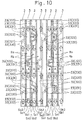
- each of the at least one barrier ridge 231, 331 is projected toward the opposed heat transfer portion 20, 30 at an intermediate position of the first flow channel Ra formed between the first surfaces Sa1, Sb1 of each two adjacent heat transfer portions 20, 30, as shown in Fig. 9 and Fig. 10 .
- This configuration allows each of the at least one barrier ridge 231, 331 to block circulation of the first fluid medium A through the first flow channel Ra to thereby increase the circulating resistance of the first fluid medium A through the first flow channel Ra.
- each of the first ridges 230, 330 of each two adjacent heat transfer plates 2, 3 is located between each two adjacent first ridges 230, 330 of the opposed heat transfer plate 2,3, and each of the at least one barrier ridge 231, 331 (each of the at least one barrier ridge 231, 331 lower than the first ridges 230, 330) of the heat transfer plate 2, 3 crosses and abuts against the first ridges 230, 330 of the opposed heat transfer plate 2, 3.
- This configuration makes small a clearance between the first surfaces Sa1, Sb1 of each two adjacent heat transfer plates 2, 3. That is, the projected amount of each of the at least one barrier ridge 231, 331 is smaller than the projected amount of the first ridges 230, 330, and consequently the heat transfer plates 2, 3 defining each of the first flow channels Ra are arranged close to each other.
- This configuration narrows the width of the first flow channel Ra to thereby increase the circulating resistance of the first fluid medium A through the first flow channel Ra.
- the circulating resistance of the first fluid medium A is increased by each of the at least one barrier ridge 231, 331 and the narrowed width of the first flow channel Ra; consequently, the first fluid medium A becomes more likely to cause the heat transfer portions 20, 30 to be subjected to thermal influences, thereby improving the performance of transferring heat to the second fluid medium B.
- liquid film of the second fluid medium B formed on the surfaces of the heat transfer portions 20, 30 is disturbed by the increased velocity of the second fluid medium B, even if a fluid medium that causes phase change (a fluid medium having two-phase flow that contains liquid and gas) is employed as the second fluid medium B.
- a fluid medium that causes phase change a fluid medium having two-phase flow that contains liquid and gas
- the heat exchanger 1 configured as above enhances heat transfer performance of the second fluid medium B circulated through the second flow channels Rb to the heat transfer portions 20, 30 (the first fluid medium A side).
- the at least one of each adjacent two of the plurality of heat transfer plates 2, 3 includes, as the ridges 23, 33 formed on the first surface Sa1, Sb1, a plurality of barrier ridges 231, 331 arranged at intervals from each other in the second direction; thus, the circulating resistance of the first fluid medium A through the first flow channels Ra can be increased according to the number of the plurality of barrier ridges 231, 331.
- each of the heat transfer portions 20, 30 of each adjacent two of the plurality of heat transfer plates 2, 3 includes, as the ridges 23, 33 formed on the second surface Sa2, Sb2, a plurality of second ridges 233, 333 being in a front-back relationship with the plurality of first valleys 220, 320, and the plurality of second ridges 233, 333 of one of each adjacent two of the plurality of heat transfer plates 2, 3 are overlapped with the plurality of second ridges 233, 333 of the opposed heat transfer plate 2, 3 and are in contact with top ends of the plurality of second ridges 233, 333 of the opposed heat transfer plate 2, 3.
- This configuration prevents the heat transfer portions 20, 30 from being expanded even if the fluid pressure of the first fluid medium A circulated through the first flow channel Ra acts on the heat transfer portions 20, 30. Therefore, the space constituting the second flow channel Rb is secured to ensure smooth circulation of the second fluid medium B.
- the at least one barrier ridge 231, 331 includes at least one bent ridge portion 232, 332, and that the at least one bent ridge portion 232, 332 includes a pair of inclined ridge portions 232a, 232b each having a proximal end and a distal end on an opposite side of the proximal end, the pair of inclined ridge portions 232a, 232b being inclined in directions opposite to each other relative to a centerline extending in the second direction or a virtual line parallel to the centerline, and having the distal ends thereof connected to each other.
- the bent ridge portion 232, 332 (the pair of inclined ridge portions 232a, 232b, 332a, 332b) of the barrier ridge 231, 331 diffuses the first fluid medium A within the first flow channel Ra. This increases the areas contributing to heat transfer in the heat transfer portions 20, 30, and consequently enhances heat transfer performance of the first fluid medium A within the first flow channel Ra.
- each of the heat transfer portions 20, 30 of each adjacent two of the plurality of heat transfer plates 2, 3 includes the at least one barrier ridge 231, 331 including the at least one bent ridge portion 232, 332, and the at least one bent ridge portion 232, 332 of the at least one barrier ridge 231, 331 of one of each adjacent two of the plurality of heat transfer plates 2, 3 is bent in a direction completely opposite to that of the at least one bent ridge portion 232, 332 of the opposed heat transfer plate 2, 3.
- the inclined ridge portions 232a, 232b, 332a, 332b of the bent ridge portions 232, 332 opposed to each other are formed to intersect with each other (see Fig. 11 ). Accordingly, the circulating resistance of the first fluid medium A within the first flow channel Ra is increased and the diffusion effect of the first fluid medium A is also increased. As a result, heat transfer performance of the first fluid medium A within the first flow channel Ra is improved.
- a plate heat exchanger 1 according to the second embodiment (hereinafter simply referred to as heat exchanger in this embodiment) includes three or more heat transfer plates 2, 3.
- the three or more heat transfer plates 2, 3 are stacked on each other in a first direction.
- the three or more heat transfer plates 2, 3 are composed of two kinds of heat transfer plates.
- the two kinds of heat transfer plates 2, 3 are arranged alternately in the first direction.
- first flow channels Ra through which a first fluid medium A is circulated and second flow channels Rb through which a second fluid medium B is circulated are alternately formed in the first direction with the heat transfer plates 2, 3 respectively interposed therebetween.
- the two kinds of heat transfer plates 2, 3 will be specifically described.
- the two kinds of heat transfer plates 2, 3 have common features and different features. First, the common features of the two kinds of heat transfer plates 2, 3 will be described.
- the heat transfer plates 2, 3 respectively include heat transfer portions 20, 30 that respectively have first surfaces Sa1, Sb1 and second surfaces Sa2, Sb2 facing opposite to the first surfaces Sa1, Sb1, and annular fitting portions 21, 31 that respectively extend from the entire outer peripheral edges of the heat transfer portions 20, 30 while having surfaces extending in a direction intersecting with the surfaces of the heat transfer portions 20, 30.
- the heat transfer portions 20, 30 have a thickness in the first direction. Accordingly, the first surfaces Sa1, Sb1 and the second surfaces Sa2, Sb2 of the heat transfer portions 20, 30 are aligned in the first direction.
- the heat transfer portions 20, 30 have an external form (contour) defined by a pair of long sides extending in a second direction orthogonal to the first direction, and a pair of short sides arranged with a distance from each other in the second direction while extending in a third direction orthogonal to the first direction and the second direction to connect the pair of long sides. That is, the heat transfer portions 20, 30 have an external form having a rectangular shape with the long sides extending in the second direction, when seen from the first direction.
- Each of the heat transfer portions 20, 30 has one end and the other end on the opposite side to the one end in the second direction.
- the heat transfer portions 20, 30 respectively have at least two openings 200, 201, 202, 203, 300, 301, 302, 303 in each of the one ends and the other ends in the second direction.
- the heat transfer portions 20, 30 respectively have two openings 200, 203, 300, 303 in the one ends in the second direction, and two openings 201, 202, 301, 302 in the other ends in the second direction.
- the two openings 200, 203, 300, 303 in the one ends in the second direction of the heat transfer portions 20, 30 are aligned in the third direction.
- the two openings 201, 202, 301, 302 in the other ends in the second direction of the heat transfer portions 20, 30 are aligned in the third direction.
- An area surrounding each of the one openings 200, 300 in the one ends and an area surrounding each of the one openings 201, 301 in the other ends in the second direction of the heat transfer portions 20, 30 are recessed on the first surfaces Sa1, Sb1 side. Accordingly, an area surrounding each of the one openings 200, 300 in the one ends and an area surrounding each of the one openings 201, 301 in the other ends in the second direction of the heat transfer portions 20, 30 are projected on the second surfaces Sa2, Sb2 side.
- the projected amounts on the second surfaces Sa2, Sb2 sides of the area surrounding each of the one openings 200, 300 and the area surrounding each of the one openings 201, 301 in the other ends in the one ends in the second direction of the heat transfer portions 20, 30 are set so that these areas can respectively contact the corresponding areas respectively surrounding the openings 200, 201, 300, 301 (i.e., the one openings 200, 300 in the one ends and the one openings 201, 301 in the other ends) of the heat transfer portions 20, 30 of each two adjacent heat transfer plates 2, 3 aligned with each other in the first direction.
- an area surrounding each of the other openings 203, 303 in the one ends and an area surrounding each of the other openings 202, 302 in the other ends in the second direction of the heat transfer portions 20, 30 are recessed on the second surfaces Sa2, Sb2 side. Accordingly, an area surrounding each of the other openings 203, 303 in the one ends and an area surrounding each of the other openings 202, 302 in the other ends in the second direction of the heat transfer portions 20, 30 are projected on the first surfaces Sa1, Sb1 side.
- the projected amounts on the first surfaces Sa1, Sb1 sides of the area surrounding each of the other openings 203, 303 in the one ends and the area surrounding each of the other openings 202, 302 in the other ends in the second direction of the heat transfer portions 20, 30 are set so that these areas can respectively contact the corresponding areas respectively surrounding the openings 202, 203, 302, 303 (i.e., the other openings 202, 302 in the one ends and the other openings 203, 303 in the other ends) of the heat transfer portions 20, 30 of each two adjacent heat transfer plates 2, 3 aligned with each other in the first direction.
- recessed areas out of the areas each surrounding the openings 200, 201, 202, 203, 300, 301, 302, 303, and bottom parts of valleys 22, 32, which will be described later, are shown in stippling to allow the relationship between the projected portions and the recessed portions of the first surfaces Sa1, Sb1 and the second surfaces Sa2, Sb2 to be distinguishable.
- the one openings 200, 300 in the one ends and the one openings 201, 301 in the other ends in the second direction of the heat transfer portions 20, 30 are located diagonal to each other, due to the configuration in which the heat transfer plates 2, 3 are stacked on each other.
- the other openings 203, 303 in the one ends and the other openings 202, 302 in the other ends in the second direction of the heat transfer portions 20, 30 are also located diagonal to each other.
- the valleys 22, 32 and ridges 23, 33 are respectively formed on each of the first surfaces Sa1, Sb1 and the second surfaces Sa2, Sb2 of the heat transfer portions 20, 30.
- Each of the first surfaces Sa1, Sb1 and the second surfaces Sa2, Sb2 of the heat transfer portions 20, 30 has a plurality (a large number) of valleys 22, 32 and a plurality (a large number) of ridges 23, 33.
- each of the heat transfer plates 2, 3 is formed by press molding of a metal plate. Accordingly, the valleys 22, 32 formed on the first surfaces Sa1, Sb1 of the heat transfer portions 20, 30 are in a front-back relationship with the ridges 23, 33 formed on the second surfaces Sa2, Sb2 of the heat transfer portions 20, 30. The ridges 23, 33 formed on the first surfaces Sa1, Sb1 of the heat transfer portions 20, 30 are in a front-back relationship with the valleys 22, 32 formed on the second surfaces Sa2, Sb2 of the heat transfer portions 20, 30.
- the deformation of the metal plate by press molding allows the valleys 22, 32 formed on the first surfaces Sa1, Sb1 of the heat transfer portions 20, 30 to be formed at positions corresponding to the positions of the ridges 23, 33 formed on the second surfaces Sa2, Sb2 of the heat transfer portions 20, 30. Also, the deformation of the metal plate by press molding allows the ridges 23, 33 formed on the first surfaces Sa1, Sb1 of the heat transfer portions 20, 30 to be formed at positions corresponding to the positions of the valleys 22, 32 formed on the second surfaces Sa2, Sb2 of the heat transfer portions 20, 30.
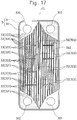
- the heat transfer portion 20, 30 includes, as the valleys 22, 32 formed on the first surface Sa1, Sb1, a plurality of first valleys 220, 320 extending in the second direction and arranged at intervals from each other in the third direction.
- the heat transfer portion 20, 30 includes, as the ridges 23, 33 formed on the first surface Sa1, Sb1, a plurality of first ridges 230, 330 each extending in the second direction between each two first valleys 220, 230 adjacent to each other in the third direction. That is, in the first surface Sa1, Sb1 of the heat transfer portion 20, 30, the first valleys 220, 320 and the first ridges 230, 330 are alternately arranged in the third direction.
- the heat transfer portion 20, 30 includes, as the ridges 23, 33 formed on the first surface Sa1, Sb1, at least one barrier ridge 231, 331 that is lower than the first ridges 230, 330 formed on the first surface Sa1, Sb1, the at least one barrier ridge 231, 331 extending in a direction intersecting with the plurality of first ridges 230, 330.
- Each of the plurality of first valleys 220, 320 has the same or substantially the same width in the third direction as each of the plurality of first ridges 230, 330.
- the internal surfaces defining the first valleys 220, 320 are continuous with the external surfaces defining the first ridges 230, 330.
- the first surface Sa1, Sb1 of the heat transfer portion 20, 30 has a corrugated shape with projections and recesses aligned in the first direction.
- the boundary between a specific first valley 220, 320 out of the plurality of first valleys 220, 320 and a specific first ridge 230, 330 out of the plurality of first ridges 230, 330 that is adjacent to the specific first valley 220, 320 is located on the vertical centerline CL of the first surface Sa1, Sb1 of the heat transfer portion 20, 30.
- the specific first valley 220, 320 or the specific first ridge 230, 330 is arranged while being displaced in the third direction from the vertical centerline CL by one-fourth of the distance between adjacent first ridges 230, 330 with one first valley 220, 320 interposed therebetween, or the distance between each two adjacent first valleys 220, 320 with one first ridge 230, 330 interposed therebetween.
- the first surface Sa1,Sb1 of the heat transfer portion 20, 30 has a plurality of barrier ridges 231, 331.
- the plurality of barrier ridges 231, 331 are arranged at intervals from each other in the second direction.
- Each of the plurality of barrier ridges 231, 331 is lower than the first ridges 230, 330 as aforementioned.
- the projected amount of the barrier ridges 231, 331 from a virtual plane (the virtual plane extending in the second direction and the third direction) passing through top ends of a plurality of second ridges 233, 333, which will be described later, formed on the second surface Sa2, Sb2 is smaller than that of the first ridges 230, 330.
- the top ends of the barrier ridges 231, 331 are located closer in the first direction to the second surface Sa2, Sb2 than the top ends of the first ridges 230, 330. That is, the top ends of the barrier ridges 231, 331 are located between the top ends of the first ridges 230, 330 and the bottom ends of the first valleys 220, 320.
- each of the first ridges 230, 330 of one heat transfer plate 2, 3 of each two adjacent heat transfer plates 2, 3 is located between each two adjacent first ridges 230, 330 (i.e., located at positions corresponding to the first valleys 220, 320) of the other heat transfer plate 2, 3 of the each two adjacent heat transfer plates 2, 3.
- the distance in the first direction between the top ends of the first ridges 230, 330 and the top ends of the barrier ridges 231, 331 is set so that the clearance between the first ridges 230, 330 of one heat transfer plate 2, 3 out of each two adjacent heat transfer plates 2, 3 and the first valleys 220, 320 of the other heat transfer plate 2, 3 can secure circulation of the first fluid medium A.
- the plurality of first valleys 220, 320 are set to have the same width and the plurality of first ridges 230, 330 are set to have the same width.
- the first valleys 220, 320 and the first ridges 230, 330 are set to have substantially the same width.
- the distance in the first direction between the top ends of the first ridges 230, 330 and the top ends of the barrier ridges 231, 331 is set so that the clearances between the both sides in the width direction of each of the first ridges 230, 330 and the both sides in the width direction of each of the first valleys 220, 320 have a distance to secure circulation of the first fluid medium A.
- the barrier ridges 231, 331 intersect with the plurality of first ridges 230, 330 and the plurality of first valleys 220, 320.
- the barrier ridges 231, 331 extend in the third direction.
- the barrier ridges 231, 331 are set to have a length shorter than the entire length in the third direction of the heat transfer portion 20, 30.
- the length is set so that each of the barrier ridges 231, 331 intersects with the first ridges 230, 330 and the first valleys 220, 320, the number of which is smaller than the total number of the plurality of first ridges 230, 330 and the plurality of first valleys 220, 320 aligned with each other over the entire length in the third direction of the heat transfer portion 20, 30.
- the length in the extending direction (longitudinal direction) of the barrier ridge 231, 331 is set to 1/2 or less of the entire length in the third direction of the heat transfer portion 20, 30.
- the length in the extending direction (longitudinal direction) of the barrier ridge 231, 331 is set to 1/3 or less of the entire length in the third direction of the heat transfer portion 20, 30.
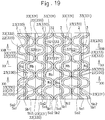
- each of the barrier ridges 231, 331 Since the length in the extending direction (longitudinal direction) of each of the barrier ridges 231, 331 is set to 1/3 or less of the entire length in the third direction of the heat transfer portion 20, 30, as described above, a plurality of rows each constituted by the plurality of barrier ridges 231, 331 aligned at intervals from each other in the second direction are provided at intervals from each other in the third direction on the first surface Sa1, Sb1 of the heat transfer portion 20, 30. That is, the plurality of barrier ridges 231, 331 are arranged in a matrix form on the first surface Sa1, Sb1 of the heat transfer portion 20, 30.
- the number and positions of the barrier ridges 231, 331 in each of the rows correspond to each other. Thus, those barrier ridges 231, 331 corresponding to each other between the different rows are aligned with each other in the third direction.
- the distance between each two adjacent rows of the barrier ridges 231, 331 is set to be equal to or less than the length in the extending direction (longitudinal direction) of each of the barrier ridges 231, 331.
- the distance between each two adjacent rows of the barrier ridges 231, 331 is set to be shorter than the length in the extending direction (longitudinal direction) of each of the barrier ridges 231, 331.
- each of the barrier ridges 231, 331 is set to 1/3 or less (1/2 or less in this embodiment) of the entire length in the third direction of the heat transfer portion 20, 30, as described above, some of the first valleys 220, 320 and the first ridges 230, 330 on the first surface Sa1, Sa2 of the heat transfer portion 20, 30 are continuous in the second direction while the remaining ones are divided at a plurality of places in the second direction by the barrier ridges 231, 331. At least one end of each of the divided first valleys 220, 320 and at least one end of each of the divided first ridges 230, 330 are joined to a corresponding one of the barrier ridges 231, 331.
- the divided first valleys 220, 320 are aligned with each other in the second direction. Accordingly, the divided first ridges 230, 330 are also aligned with each other in the second direction.
- the heat transfer portion 20, 30 includes, as the valleys 22, 32 formed on the second surface Sa2, Sb2, a plurality of second valleys 221, 321 extending in the second direction and arranged at intervals from each other in the third direction.
- the heat transfer portion 20, 30 includes, as the ridges 23, 33 formed on the second surface Sa2, Sb2, a plurality of second ridges 233, 333 each extending in the second direction between each two second valleys 221, 231 adjacent to each other in the third direction. That is, in the second surface Sa2, Sb2 of the heat transfer portion 20, 30, the second valleys 221, 321 and the second ridges 233, 333 are alternately arranged in the third direction.
- the heat transfer portion 20, 30 includes, as the valleys 22, 32 formed on the second surface Sa2, Sb2, valleys (hereinafter referred to as back side valleys) 222, 322 formed respectively on the back sides of the barrier ridges 231, 331 on the first surface Sa1, Sb1.
- the second valleys 221, 321 are the valleys 22, 32 formed on the back sides of the first ridges 230, 330 on the first surface Sa1, Sb1. Thus, the second valleys 221, 321 extend in the second direction.
- the second ridges 233, 333 are the ridges 23, 33 formed on the back sides of the first valleys 220 and 320 on the first surface Sa1, Sb1. Thus, the second ridges 233, 333 extend in the second direction.
- the internal surfaces defining the second valleys 221, 321 are continuous with the external surfaces defining the second ridges 233, 333.
- the second surface Sa2, Sb2 of the heat transfer portion 20, 30 has a corrugated shape with projections and recesses in the third direction.
- the back side valleys 222, 322 are formed in the same pattern as the barrier ridges 231, 331 except that they have a reversed concavo-convex relationship.
- the back side valleys 222, 322 intersect with the plurality of second ridges 233, 333 and the plurality of second valleys 221, 321.
- the back side valleys 222, 322 are set to have a length shorter than the entire length in the third direction of the heat transfer portion 20, 30. That is, the length is set so that each of the back side valleys 222, 322 intersects with the second ridges 233, 333 and the second valleys 221, 321, the number of which is smaller than the total number of the plurality of second ridges 233, 333 and the plurality of second valleys 221, 321 aligned with each other over the entire length in the third direction of the heat transfer portion 20, 30.
- the length in the extending direction (longitudinal direction) of the back side valley 222, 322 is set to 1/2 or less of the entire length in the third direction of the heat transfer portion 20, 30.
- the length in the extending direction (longitudinal direction) of the back side valley 222, 322 is set to 1/3 or less of the entire length in the third direction of the heat transfer portion 20, 30.
- each of the back side valleys 222, 322 Since the length in the extending direction (longitudinal direction) of each of the back side valleys 222, 322 is set to 1/3 or less of the entire length in the third direction of the heat transfer portion 20, 30, as described above, a plurality of rows each constituted by the plurality of back side valleys 222, 322 aligned at intervals from each other in the second direction are provided at intervals from each other in the third direction on the second surface Sa2, Sb2 of the heat transfer portion 20, 30. That is, the plurality of back side valleys 222, 322 are arranged in a matrix form on the second surface Sa2, Sb2 of the heat transfer portion 20, 30.
- the number and positions of the back side valleys 222, 322 in each of the rows correspond to each other. Thus, those back side valleys 222, 322 corresponding to each other between the different rows are aligned with each other in the third direction.
- the distance between each two adjacent rows of the back side valleys 222, 322 is set to be equal to or less than the length in the extending direction (longitudinal direction) of each of the back side valleys 222, 322.
- the distance between each two adjacent rows of the back side valleys 222, 322 is set to be shorter than the length in the extending direction (longitudinal direction) of each of the back side valleys 222, 322.
- each of the back side valleys 222, 322 is set to 1/3 or less (1/2 or less in this embodiment) of the entire length in the third direction of the heat transfer portion 20, 30, as described above, some of the second valleys 221, 321 and the second ridges 233, 333 on the second surface Sa2, Sa2 of the heat transfer portion 20, 30 are continuous in the second direction while the remaining ones are divided at a plurality of places in the second direction by the back side valleys 222, 322. At least one end of each of the divided second valleys 221, 321 and at least one end of each of the divided second ridges 233, 333 are joined to a corresponding one of the back side valleys 222, 322. That is, the divided second valleys 221, 321 are open to the inside of the back side valleys 222, 322.
- the divided second valleys 221, 321 are aligned with each other in the second direction. Accordingly, the divided second ridges 233, 333 are also aligned with each other in the second direction.
- first heat transfer plate first heat transfer plate
- second heat transfer plate second heat transfer plate
- the first valleys 220, 320 and the first ridges 230, 330 are respectively arranged so that the first ridges 230 of the first heat transfer plate 2 are opposed to the first valleys 320 of the second heat transfer plate 3 and that the first ridges 330 of the second heat transfer plate 3 are opposed to the first valleys 220 of the first heat transfer plate 2.
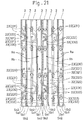
- the first heat transfer plate 2 and the second heat transfer plate 3 are different from each other in the number and arrangement pattern of the barrier ridges 231, 331 on the first surfaces Sa1, Sb1. That is, the first heat transfer plate 2 and the second heat transfer plate 3 are different from each other in the number of rows of the barrier ridges 231, 331 on the first surfaces Sa1, Sb1 and the arrangement pattern of the barrier ridges 231, 331 in each of the rows.
- the number of rows of the barrier ridges 331 arranged at intervals from each other in the third direction on the first surface Sb 1 of the heat transfer plate 3 is smaller by one than the number of rows of the barrier ridges 231 arranged at intervals from each other in the third direction on the first surface Sa1 of the heat transfer plate 2. Further, the number of barrier ridges 231 in each of the rows on the first surface Sb1 of the second heat transfer plate 3 is smaller by one than the number of barrier ridges 231 in each of the rows on the first surface Sa1 of the first heat transfer plate 2.
- the position of each of the rows of the barrier ridges 231 on the first surface Sa1 of the first heat transfer plate 2 corresponds to the position between each two adjacent rows of the barrier ridges 331 on the first surface Sb1 of the second heat transfer plate 3
- the position of each of the barrier ridges 331 on the first surface Sb1 of the second heat transfer plate 3 corresponds to the position between each two adjacent rows of the barrier ridges 231 on the first surface Sa1 of the first heat transfer plate 2.
- each of the barrier ridges 231 in each of the rows on the first surface Sa1 of the first heat transfer plate 2 corresponds to the position between each two adjacent barrier ridges 331 in each of the rows on the first surface Sb1 of the second heat transfer plate 3 (i.e., the intermediate position between each two adjacent barrier ridges 331 in the second direction), and the position of each of the barrier ridges 331 in each of the rows on the first surface Sb1 of the second heat transfer plate 3 corresponds to the position between each two adjacent barrier ridges 231 in each of the rows on the first surface Sa1 of the first heat transfer plate 2 (i.e., the intermediate position between each two adjacent barrier ridges 231 in the second direction).
- each of the first heat transfer plates 2 includes the fitting portion 21 projecting on the first surface Sa1 side of the heat transfer portion 20.
- each of the second heat transfer plates 3 includes the fitting portion 31 projecting on the second surface Sb2 side of the heat transfer portion 30.
- each of the plurality of heat transfer plates 2, 3 has been described as above.
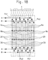
- the plurality of heat transfer plates 2, 3 (the first heat transfer plates 2 and the second heat transfer plates 3) are stacked on each other in the first direction, as shown in Fig. 13 .
- the first heat transfer plates 2 and the second heat transfer plates 3 are alternately stacked on each other in the first direction.
- each of the plurality of heat transfer plates 2, 3 has the first surface Sa1, Sb1 of its heat transfer portion 20, 30 opposed to the first surface Sa1, Sb1 of the heat transfer portion 20, 30 of the adjacent heat transfer plate 2, 3 on one side in the first direction.
- each of the plurality of heat transfer plates 2, 3 has the second surface Sa2, Sb2 of its heat transfer portion 20, 30 opposed to the second surface Sa2, Sb2 of the heat transfer portion 20, 30 of the adjacent heat transfer plate 2, 3 on the other side in the first direction.
- each of the first flow channels Ra through which the first fluid medium A is circulated in the second direction and the second flow channels Rb through which the second fluid medium B is circulated in the second direction are alternately formed with the heat transfer portions 20, 30 of the heat transfer plates 2, 3 respectively interposed therebetween. That is, each of the first flow channels Ra through which the first fluid medium A is circulated is formed between the first surfaces Sa1, Sb1 of the heat transfer portions 20, 30 of each two adjacent heat transfer plates 2, 3, and each of the second flow channels Ra through which the second fluid medium B is circulated is formed between the second surfaces Sa2, Sb2 of the heat transfer portions 20, 30 of each two adjacent heat transfer plates 2, 3.
- the openings 200, 201, 202, 203, 300, 301, 302, 303 located in the corresponding positions of the heat transfer portions 20, 30 are lined up in the first direction, as shown in Fig. 13 .
- the areas respectively surrounding the openings 200, 201, 202, 203, 300, 301, 302, 303 that are opposed to and projected toward each other contact each other.
- This configuration forms the first inflow channel Pa1 for supplying the first fluid medium A into the first flow channels Ra, the first outflow channel Pa2 for causing the first fluid medium A to flow out of the first flow channels Ra, the second inflow channel Pb 1 for supplying the second fluid medium B into the second flow channels Rb, and the second outflow channel Pb2 for causing the second fluid medium B to flow out of the second flow channels Rb.
- each of the first heat transfer plates 2 and each of the second heat transfer plates 3 are stacked on each other to form a pair.
- every other pair is turned 180 degrees upside down about a virtual line extending in the first direction.
- the fitting portion 21, 31 of one heat transfer plate 2, 3 (the first heat transfer plate 2 or the second heat transfer plate 3) out of the heat transfer plates 2, 3 adjacent to each other in the first direction is fitted over the fitting portion 21, 31 of the other heat transfer plate 2, 3 (the first heat transfer plate 2 or the second heat transfer plate 3) out of the heat transfer plates 2, 3 adjacent to each other in the first direction.
- the barrier ridges 231 are lower than the first ridges 230, and on the second heat transfer plate 3, the barrier ridges 331 are lower than the first ridges 330; thus, the barrier ridges 231 of the first heat transfer plate 2 cross and abut against the first ridges 330 of the second heat transfer plate 3, and the barrier ridges 331 of the second heat transfer plate 3 cross and abut against the first ridges 230 of the first heat transfer plate 2.
- the boundary between a specific first valley 220, 320 out of the plurality of first valleys 220, 320 and a specific first ridge 230, 330 out of the plurality of first ridges 230, 330 that is adjacent to the specific first valley 220, 320 is located on the vertical centerline CL.
- turning the first heat transfer plates 2 and the second heat transfer plates 3 180° upside down as aforementioned causes the second ridges 233, 333 of each two adjacent heat transfer plates 2, 3 to be opposed to each other and causes their top ends to be in contact with each other.
- the first flow channel Ra through which the first fluid medium A is circulated in the second direction orthogonal to the first direction is formed between the first surfaces Sa1, Sb1 of the heat transfer portions 20, 30 of each two adjacent heat transfer plates 2, 3.
- the second flow channel Rb through which the second fluid medium B is circulated in the second direction is formed between the second surfaces Sa2, Sb2 of the heat transfer portions 20, 30 of each two adjacent heat transfer plates 2, 3.
- the plurality of heat transfer plates 2, 3 are stacked on each other in the first direction so that the openings 200, 201, 202, 203, 300, 301, 302, 303 located in the corresponding positions of the heat transfer portions 20, 30 are lined up in the first direction.
- the areas respectively surrounding the openings 200, 201, 202, 203, 300, 301, 302, 303 that are opposed to and projected toward each other contact each other.
- This configuration forms the first inflow channel Pa1 for supplying the first fluid medium A into the first flow channels Ra, the first outflow channel Pa2 for causing the first fluid medium A to flow out of the first flow channels Ra, the second inflow channel Pb 1 for supplying the second fluid medium B into the second flow channels Rb, and the second outflow channel Pb2 for causing the second fluid medium B to flow out of the second flow channels Rb.
- the contacted portions between each two adjacent heat transfer plates 2, 3 are brazed together.
- This configuration allows the plurality of heat transfer plates 2, 3 to be integrally (mechanically) connected to each other, and an interface between the opposed surfaces (contacted portions) of the adjacent heat transfer plates 2, 3 to be sealed.
- the heat exchanger 1 has been described as above.
- the first fluid medium A flows from the first inflow channel Pa1 into the plurality of first flow channels Ra.
- the first fluid medium A is circulated through each of the first flow channels Ra in the second direction, and flows out to the first outflow channel Pa2.
- the second fluid medium B flows from the second inflow channel Pb 1 into the plurality of second flow channels Rb.
- the second fluid medium B is circulated through each of the plurality of second flow channels Rb in the second direction, and flows out to the second outflow channel Pb2.
- the first fluid medium A is circulated through each of the first flow channels Ra with a diagonal line connecting opposing corners of the heat transfer portion 20, 30 as a center of flow.
- the second fluid medium B is circulated through each of the second flow channels Rb with another diagonal line connecting opposing corners of the heat transfer portion 20, 30 as a center of flow, which is different from the diagonal line being the center of the flow of the first fluid medium A.
- the first fluid medium A that is circulated through the first flow channels Ra and the second fluid medium B that is circulated through the second flow channels Rb exchange heat via the heat transfer plates 2, 3 (the heat transfer portions 20, 30) that separate the first flow channels Ra and the second flow channels Rb.
- the second fluid medium B is condensed or evaporated in the course of being circulated through the second flow channels Rb in the second direction.
- a plate heat exchanger 1 includes a plurality of heat transfer plates 2, 3 each including a heat transfer portion 20, 30 having a first surface Sa1, Sb1 on which ridges 23, 33 and valleys 22, 32 are formed, and a second surface Sa2, Sb2 that is opposed to the first surface Sa1, Sb1 and on which valleys 22, 32 being in a front-back relationship with the ridges 23, 33 of the first surface Sa1, Sb1 and ridges 23, 33 being in a front-back relationship with the valleys 22, 32 of the first surface Sa1, Sb1 are formed, the plurality of heat transfer plates 2, 3 respectively having the heat transfer portions 20, 30 stacked on each other in a first direction, wherein the first surface Sa1, Sb1 of the heat transfer portion 20, 30 of each of the plurality of heat transfer plates 2, 3 is arranged opposed to the first surface Sa1, Sb1 of the heat transfer portion 20, 30 of one of the plurality of heat transfer plates 2, 3 adjacent to the each heat transfer plate 2, 3 on one side in the first direction, and the second surface
- each of the at least one barrier ridge 231, 331 is projected toward the opposed heat transfer portion 20, 30 at an intermediate position of the first flow channel Ra formed between the first surfaces Sa1, Sb1 of each two adjacent heat transfer portions 20, 30, as shown in Fig. 20 to Fig. 22 .
- This configuration allows each of the at least one barrier ridge 231, 331 to block circulation of the first fluid medium A through the first flow channel Ra to thereby increase the circulating resistance of the first fluid medium A through the first flow channel Ra.
- each of the first ridges 230, 330 of each two adjacent heat transfer plates 2, 3 is located between each two adjacent first ridges 230, 330 of the opposed heat transfer plate 2,3, and each of the at least one barrier ridge 231, 331 (each of the at least one barrier ridge 231, 331 lower than the first ridges 230, 330) of the heat transfer plate 2, 3 crosses and abuts against the first ridges 230, 330 of the opposed heat transfer plate 2, 3.
- This configuration makes small a clearance between the first surfaces Sa1, Sb1 of each two adjacent heat transfer plates 2, 3. That is, the projected amount of each of the at least one barrier ridge 231, 331 is smaller than the projected amount of the first ridges 230, 330, and consequently the heat transfer plates 2, 3 defining each of the first flow channels Ra are arranged close to each other.
- This configuration narrows the width of the first flow channel Ra to thereby increase the circulating resistance of the first fluid medium A through the first flow channel Ra.
- the circulating resistance of the first fluid medium A is increased by each of the at least one barrier ridge 231, 331 and the narrowed width of the first flow channel Ra; consequently, the first fluid medium A becomes more likely to cause the heat transfer portions 20, 30 to be subjected to thermal influences, thereby improving the performance of transferring heat to the second fluid medium B.
- liquid film of the second fluid medium B formed on the surfaces of the heat transfer portions 20, 30 is disturbed by the increased velocity of the second fluid medium B, even if a fluid medium that causes phase change (a fluid medium having two-phase flow that contains liquid and gas) is employed as the second fluid medium B.
- a fluid medium that causes phase change a fluid medium having two-phase flow that contains liquid and gas
- the heat exchanger 1 configured as above enhances heat transfer performance of the second fluid medium B circulated through the second flow channels Rb to the heat transfer portions 20, 30 (the first fluid medium A side).
- the at least one of each adjacent two of the plurality of heat transfer plates 2, 3 includes, as the ridges 23, 33 formed on the first surface Sa1, Sb1, a plurality of barrier ridges 231, 331 arranged at intervals from each other in the second direction; thus, the circulating resistance of the first fluid medium A through the first flow channels Ra can be increased according to the number of the plurality of barrier ridges 231, 331.
- each of the heat transfer portions 20, 30 of each adjacent two of the plurality of heat transfer plates 2, 3 includes, as the ridges 23, 33 formed on the second surface Sa2, Sb2, a plurality of second ridges 233, 333 being in a front-back relationship with the plurality of first valleys 220, 320, and the plurality of second ridges 233, 333 of one of each adjacent two of the plurality of heat transfer plates 2, 3 are overlapped with the plurality of second ridges 233, 333 of the opposed heat transfer plate 2, 3 and are in contact with top ends of the plurality of second ridges 233, 333 of the opposed heat transfer plate 2, 3.
- This configuration prevents the heat transfer portions 20, 30 from being expanded even if the fluid pressure of the first fluid medium A circulated through the first flow channel Ra acts on the heat transfer portions 20, 30. Therefore, the space constituting the second flow channel Rb is secured to ensure smooth circulation of the second fluid medium B.
- the plurality of barrier ridges 231, 331 extending in the third direction are arranged at intervals from each other in the second direction, and the plurality of barrier ridges 231, 331 each have a length shorter than the entire length in the third direction of the heat transfer portion 20, 30; thus, the first fluid medium A circulates through the first flow channel Ra while avoiding the plurality of barrier ridges 231, 331 therein that cause resistance. As a result, the first fluid medium A is diffused within the first flow channel Ra. This increases the areas contributing to heat transfer in the heat transfer portions 20, 30, and consequently enhances heat transfer performance of the first fluid medium A within the first flow channel Ra.
- the barrier ridges 231, 331 are respectively provided on the first surfaces Sa1, Sb1 of each two adjacent heat transfer plates 2, 3 and the barrier ridges 231, 331 of the each two adjacent heat transfer plates 2, 3 are arranged while being displaced from each other in the second direction, the first flow channel Ra is not closed by the barrier ridges 231, 331, thereby increasing diffusibility within the first flow channel Ra.
- the first flow channel Ra is not closed by the barrier ridges 231, 331, thereby further increasing diffusibility within the first flow channel Ra.
- each of the aforementioned embodiments was described by taking, for example, the case where each of two adjacent heat transfer plates 2, 3 (the first heat transfer plate 2 and the heat transfer plate 3) includes the barrier ridges 231, 331 as the ridges on the first surfaces Sa1, Sb1, without limitation thereto.
- each two adjacent heat transfer plates 2, 3 may include the barrier ridges 231, 331 as the ridges on the first surfaces Sa1, Sb1.
- each of the aforementioned embodiments was described by taking, for example, the case where the top ends of the second ridges 233, 333 of each two adjacent heat transfer plates 2, 3 (the first heat transfer plate 2 and the second heat transfer plate 3) are in contact with or connected to each other, without limitation thereto.
- the top ends of the second ridges 233, 333 of the each two adjacent heat transfer plates 2, 3 (the first heat transfer plate 2 and the second heat transfer plate 3) may be away from each other in the first direction or in the second direction.
- the top ends of the second ridges 233, 333 of each two adjacent heat transfer plates 2, 3 (the first heat transfer plate 2 and the second heat transfer plate 3) be in contact with or connected to each other, as in the cases of the aforementioned embodiments.
- the second valleys 221, 321 may extend in a synthetic direction that has a component in the second direction (i.e., in a direction inclined relative to a virtual line extending in the second direction), with the prerequisite that they are continuous with the back side valleys 222, 322.
- the back side valleys 222, 322 are required to be inclined, satisfying the condition that the inclination component (angle) relative to the virtual line extending in the second direction is smaller than the inclination component (angle) relative to the virtual line extending in the third direction.
- Each of the aforementioned embodiments was described by taking, for example, the case where two or more barrier ridges 231, 331 are provided at intervals from each other in the second direction, without limitation thereto.
- one barrier ridge 231, 331 may be provided on one heat transfer portion 20, 30.
- the aforementioned second embodiment was described by taking, for example, the case where two or more rows each constituted by the plurality of barrier ridges 231, 331 arranged at intervals from each other in the second direction are provided at intervals from each other in the third direction, without limitation thereto.
- the plurality of barrier ridges 231, 331 arranged at intervals from each other in the second direction to be aligned in one row may be provided on each of the first surfaces Sa1, Sb1 of the heat transfer portions 20, 30.
- the aforementioned second embodiment was described by taking, for example, the case where the plurality of barrier ridges 231, 331 arranged at intervals from each other in the second direction are lined up in the second direction on each of the first surfaces Sa1, Sb1 of the heat transfer portions 20, 30, without limitation thereto.
- the plurality of barrier ridges 231, 331 arranged at intervals from each other in the second direction may be arranged while being displaced from each other in the third direction.
- each of the aforementioned embodiments was described by taking, for example, the case where the plurality of barrier ridges 231, 331 formed on the first surfaces Sa1, Sb1 of the heat transfer portions 20, 30 are formed into the same shape, without limitation thereto.
- the plurality of barrier ridges 231, 331 in different shapes may be formed on the first surfaces Sa1, Sb1 of the heat transfer portions 20, 30.
- first valleys 220, 320 and the first ridges 230, 330 are set to have the same width dimension (i.e., the dimension in the direction orthogonal to the longitudinal direction), without limitation thereto.
- the width dimension of the first valleys 220, 320 may be set to be larger than the width dimension of the first ridges 230, 330.
- Fig. 25 to Fig. 27 the width dimension of the first valleys 220, 320 may be set to be larger than the width dimension of the first ridges 230, 330.
- the radius of curvature of the first valleys 220, 320 may be set to be larger than the radius of curvature of the first ridges 230, 330, with the prerequisite that the first valleys 220, 320 and the first ridges 230, 330 have an arc-shaped cross section.
- the first valleys 220, 320 may be formed to have a flat bottom and have a width dimension larger than the width dimension of the first ridges 230, 330.
- the first ridges 230, 330 may have an arc-shaped cross section as shown in Fig. 26 , or may have a flat top end as shown in Fig. 27 .
- This configuration allows the barrier ridges 231, 331 lower than the first ridges 230, 330 to cross and abut against the first ridges 230, 330 of the opposed heat transfer plate 2, 3.
- the first ridges 230, 330 are arranged to be close to or fit into the first valleys 220, 320, no extremely narrow clearance is formed between the first valleys 220, 320 and the first ridges 230, 330, thereby securing circulation of the fist fluid medium A.
- At least two second flow channels Rb may be communicated with each other by a connection flow channel PJ that extends in the first direction at a position different from the second inflow channel Pb1 and the second outflow channel Pb2 so that the second flow channel Rb located most upstream of the circulation route including the connection flow channel PJ of the second fluid medium B is connected to the second inflow channel Pb 1 and the second flow channel Rb located most downstream of the circulation route including the connection flow channel PJ of the second fluid medium B is connected to the second outflow channel Pb2.
- a branch reference space Ds1 is formed between two adjacent heat transfer plates 2, 3 at an intermediate position in a direction in which the heat transfer plates 2, 3 are stacked on each other (i.e., in the first direction).
- the configuration may be such that one of the second flow channels Rb located on one side in the first direction of the branch reference space Ds1 is connected to the branch reference space Ds1 via the connection flow channel PJ, and that one of the second flow channels Rb located on the other side in the first direction of the branch reference space Ds1 is connected to the branch reference space Ds1 via the connection flow channel PJ.
- This configuration allows the circulation route of the second fluid medium B to be branched into at least one first system S1 that is continuous on the one side in the first direction of the branch reference space Ds1 and at least one second system S2 that is continuous on the other side in the first direction of the branch reference space Ds1.
- each of the first system S1 and the second system S2 may have a branch reference space (branch reference space on the downstream side) Ds2 formed between two adjacent heat transfer plates 2, 3 that define at least one second flow channel Rb located at an intermediate position in the first direction and directly or indirectly connected to the branch reference space Ds1 upstream thereof via the connection flow channel PJ.
- branch reference space branch reference space on the downstream side
- the second flow channel Rb located on one side in the first direction of the branch reference space Ds2 is connected to the branch reference space Ds2 on the downstream side via the connection flow channel PJ
- the second flow channel Rb located on the other side in the first direction of the branch reference space Ds2 is connected to the branch reference space Ds2 on the downstream side via the connection flow channel PJ.
- This configuration allows the circulation route of the second fluid medium B in each of the first system S1 and the second system S2 to be further branched into at least two systems S1a, S1b, S2a, S2b, and the second flow channel Rb located most downstream of each of the systems S1a, S1b, S2a, S2b to be connected to the second outflow channel Pb2.
- the barrier ridges 231, 331 including the bent ridge portion 232, 332 are formed over the entire length in the third direction of the heat transfer portion 20, 30, without limitation thereto.
- the barrier ridges 231, 331 may include a plurality of (two or more) bent ridge portions 232, 332.
- the barrier ridges 231, 331 may be formed into a curved shape when seen from the first direction.
- the barrier ridges 231, 331 may be formed into a corrugated shape with a plurality of curved portions joined to each other when seen from the first direction.
- the barrier ridges 231, 331 having a linear shape over the entire length may be formed over the entire length in the third direction of the heat transfer portion 20, 30.
- the barrier ridges 231, 331 are provided on both of each two adjacent heat transfer plates 2, 3, the barrier ridges 231, 331 of one of the each two adjacent heat transfer plates 2, 3 are arranged while being displaced in the second direction relative to the barrier ridges 231, 331 of the other one of the each two adjacent heat transfer plates 2, 3.
- This configuration prevents the first flow channel Ra from being closed by the barrier ridges 231, 331 that are contact with each other over their entire length, and can achieve the same operations and effects as those of the aforementioned embodiments.
- the aforementioned second embodiment was described by taking, for example, the case where the plurality of barrier ridges 231, 331 extend straight in the third direction, without limitation thereto.
- the plurality of barrier ridges 231, 331 may include the bent ridge portion 232, 332, similar to the first embodiment.
- the barrier ridges 231, 331 of each two adjacent heat transfer plates 2, 3 may intersect with each other when seen from the first direction.
- the aforementioned second embodiment was described by taking, for example, the case where the barrier ridges 231, 331 are provided while intersecting with the plurality of first ridges 230, 330, without limitation thereto.
- the barrier ridges 231, 331 may extend in a direction intersecting with the first ridges 230, 330.
- each of the barrier ridges 231, 331 may be so short that it intersects only with a single first ridge 230, 330, or lies between each two adjacent first ridges 230, 330 (i.e., within a single first valley 220, 320), with the prerequisite that the barrier ridges 231, 331 extend in a direction intersecting with the first ridges 230, 330 (i.e., the top ends (ridge lines) of the barrier ridges 231, 331 extend in a direction intersecting with the first ridges 230, 330).
Landscapes
- Engineering & Computer Science (AREA)
- Physics & Mathematics (AREA)
- Thermal Sciences (AREA)
- Mechanical Engineering (AREA)
- General Engineering & Computer Science (AREA)
- Heat-Exchange Devices With Radiators And Conduit Assemblies (AREA)
Applications Claiming Priority (1)
| Application Number | Priority Date | Filing Date | Title |
|---|---|---|---|
| PCT/JP2017/019550 WO2018216166A1 (fr) | 2017-05-25 | 2017-05-25 | Échangeur de chaleur de type à plaques |
Publications (4)
| Publication Number | Publication Date |
|---|---|
| EP3627087A1 true EP3627087A1 (fr) | 2020-03-25 |
| EP3627087A4 EP3627087A4 (fr) | 2021-01-20 |
| EP3627087B1 EP3627087B1 (fr) | 2023-08-23 |
| EP3627087C0 EP3627087C0 (fr) | 2023-08-23 |
Family
ID=64396295
Family Applications (1)
| Application Number | Title | Priority Date | Filing Date |
|---|---|---|---|
| EP17911106.7A Active EP3627087B1 (fr) | 2017-05-25 | 2017-05-25 | Échangeur de chaleur de type à plaques |
Country Status (4)
| Country | Link |
|---|---|
| EP (1) | EP3627087B1 (fr) |
| JP (1) | JP6799681B2 (fr) |
| CN (1) | CN110662937B (fr) |
| WO (1) | WO2018216166A1 (fr) |
Cited By (1)
| Publication number | Priority date | Publication date | Assignee | Title |
|---|---|---|---|---|
| US11874076B2 (en) | 2020-02-27 | 2024-01-16 | Mitsubishi Heavy Industries, Ltd. | Heat exchanger core and heat exchanger |
Families Citing this family (1)
| Publication number | Priority date | Publication date | Assignee | Title |
|---|---|---|---|---|
| JP7294126B2 (ja) * | 2019-12-26 | 2023-06-20 | トヨタ自動車株式会社 | 冷却器 |
Family Cites Families (14)
| Publication number | Priority date | Publication date | Assignee | Title |
|---|---|---|---|---|
| GB580368A (en) * | 1944-01-01 | 1946-09-05 | Separator Ab | Improvements in or relating to plate heat exchangers |
| JPS5710353B2 (fr) * | 1972-12-21 | 1982-02-25 | ||
| US4182411A (en) * | 1975-12-19 | 1980-01-08 | Hisaka Works Ltd. | Plate type condenser |
| JPS55107898A (en) * | 1979-02-12 | 1980-08-19 | Union Carbide Corp | Heat exchanger wall member and heat exchanger using same |
| JPS5664292A (en) * | 1979-10-30 | 1981-06-01 | Hisaka Works Ltd | Plate type heat exchanger |
| JPS5699293U (fr) * | 1979-12-22 | 1981-08-05 | ||
| JPS625097A (ja) * | 1985-06-28 | 1987-01-12 | Nippon Denso Co Ltd | 積層型熱交換器 |
| JP3212350B2 (ja) * | 1992-03-30 | 2001-09-25 | 株式会社日阪製作所 | プレート式熱交換器 |
| CN1109232C (zh) * | 1993-12-28 | 2003-05-21 | 昭和电工株式会社 | 板式热交换器 |
| US5899261A (en) * | 1997-09-15 | 1999-05-04 | Abb Air Preheater, Inc. | Air preheater heat transfer surface |
| JP3976418B2 (ja) * | 1998-10-13 | 2007-09-19 | 本田技研工業株式会社 | 多板式熱交換器 |
| JP2001099588A (ja) | 1999-09-29 | 2001-04-13 | Hisaka Works Ltd | プレート式熱交換器 |
| CN2529188Y (zh) * | 2002-03-08 | 2003-01-01 | 崔凤翎 | 板式换热器 |
| DK2508831T3 (en) * | 2011-04-07 | 2016-03-07 | Alfa Laval Corp Ab | PLATE HEAT EXCHANGE |
-
2017
- 2017-05-25 JP JP2019519902A patent/JP6799681B2/ja active Active
- 2017-05-25 EP EP17911106.7A patent/EP3627087B1/fr active Active
- 2017-05-25 WO PCT/JP2017/019550 patent/WO2018216166A1/fr not_active Ceased
- 2017-05-25 CN CN201780091159.0A patent/CN110662937B/zh active Active
Cited By (1)
| Publication number | Priority date | Publication date | Assignee | Title |
|---|---|---|---|---|
| US11874076B2 (en) | 2020-02-27 | 2024-01-16 | Mitsubishi Heavy Industries, Ltd. | Heat exchanger core and heat exchanger |
Also Published As
| Publication number | Publication date |
|---|---|
| EP3627087A4 (fr) | 2021-01-20 |
| JPWO2018216166A1 (ja) | 2020-04-23 |
| CN110662937A (zh) | 2020-01-07 |
| JP6799681B2 (ja) | 2020-12-16 |
| EP3627087B1 (fr) | 2023-08-23 |
| WO2018216166A1 (fr) | 2018-11-29 |
| CN110662937B (zh) | 2021-05-14 |
| EP3627087C0 (fr) | 2023-08-23 |
Similar Documents
| Publication | Publication Date | Title |
|---|---|---|
| EP3404350B1 (fr) | Échangeur de chaleur à plaques | |
| US6823934B2 (en) | Heat transfer plate and plate pack for use in a plate heat exchanger | |
| CN102859312B (zh) | 板式换热器板和板式换热器 | |
| CN112313466B (zh) | 传热板和垫圈 | |
| EP3647710B1 (fr) | Échangeur de chaleur de type à plaques | |
| US10767933B2 (en) | Heat exchanger plate for a plate heat exchanger, and a plate heat exchanger | |
| KR20060089162A (ko) | 열 교환용 플레이트 | |
| EP3627087A1 (fr) | Échangeur de chaleur de type à plaques | |
| JP2004184075A (ja) | 伝熱プレート及びプレート式熱交換器 | |
| JP5085723B2 (ja) | プレート式熱交換器 | |
| JP7100074B2 (ja) | プレート式熱交換器 | |
| CN116265854A (zh) | 双板式热交换器 | |
| CN115523776B (zh) | 热交换器 | |
| JP6235645B2 (ja) | プレート式熱交換器 | |
| JP5244162B2 (ja) | プレート式熱交換器 | |
| JP7194764B2 (ja) | プレート式熱交換器 |
Legal Events
| Date | Code | Title | Description |
|---|---|---|---|
| STAA | Information on the status of an ep patent application or granted ep patent |
Free format text: STATUS: THE INTERNATIONAL PUBLICATION HAS BEEN MADE |
|
| PUAI | Public reference made under article 153(3) epc to a published international application that has entered the european phase |
Free format text: ORIGINAL CODE: 0009012 |
|
| STAA | Information on the status of an ep patent application or granted ep patent |
Free format text: STATUS: REQUEST FOR EXAMINATION WAS MADE |
|
| 17P | Request for examination filed |
Effective date: 20191220 |
|
| AK | Designated contracting states |
Kind code of ref document: A1 Designated state(s): AL AT BE BG CH CY CZ DE DK EE ES FI FR GB GR HR HU IE IS IT LI LT LU LV MC MK MT NL NO PL PT RO RS SE SI SK SM TR |
|
| AX | Request for extension of the european patent |
Extension state: BA ME |
|
| DAV | Request for validation of the european patent (deleted) | ||
| DAX | Request for extension of the european patent (deleted) | ||
| A4 | Supplementary search report drawn up and despatched |
Effective date: 20201221 |
|
| RIC1 | Information provided on ipc code assigned before grant |
Ipc: F28F 3/04 20060101AFI20201215BHEP Ipc: F28D 9/02 20060101ALI20201215BHEP |
|
| GRAP | Despatch of communication of intention to grant a patent |
Free format text: ORIGINAL CODE: EPIDOSNIGR1 |
|
| STAA | Information on the status of an ep patent application or granted ep patent |
Free format text: STATUS: GRANT OF PATENT IS INTENDED |
|
| INTG | Intention to grant announced |
Effective date: 20230313 |
|
| GRAS | Grant fee paid |
Free format text: ORIGINAL CODE: EPIDOSNIGR3 |
|
| GRAA | (expected) grant |
Free format text: ORIGINAL CODE: 0009210 |
|
| STAA | Information on the status of an ep patent application or granted ep patent |
Free format text: STATUS: THE PATENT HAS BEEN GRANTED |
|
| AK | Designated contracting states |
Kind code of ref document: B1 Designated state(s): AL AT BE BG CH CY CZ DE DK EE ES FI FR GB GR HR HU IE IS IT LI LT LU LV MC MK MT NL NO PL PT RO RS SE SI SK SM TR |
|
| REG | Reference to a national code |
Ref country code: GB Ref legal event code: FG4D |
|
| REG | Reference to a national code |
Ref country code: CH Ref legal event code: EP |
|
| REG | Reference to a national code |
Ref country code: IE Ref legal event code: FG4D |
|
| REG | Reference to a national code |
Ref country code: DE Ref legal event code: R096 Ref document number: 602017073274 Country of ref document: DE |
|
| U01 | Request for unitary effect filed |
Effective date: 20230913 |
|
| U07 | Unitary effect registered |
Designated state(s): AT BE BG DE DK EE FI FR IT LT LU LV MT NL PT SE SI Effective date: 20230921 |
|
| PG25 | Lapsed in a contracting state [announced via postgrant information from national office to epo] |
Ref country code: GR Free format text: LAPSE BECAUSE OF FAILURE TO SUBMIT A TRANSLATION OF THE DESCRIPTION OR TO PAY THE FEE WITHIN THE PRESCRIBED TIME-LIMIT Effective date: 20231124 |
|
| PG25 | Lapsed in a contracting state [announced via postgrant information from national office to epo] |
Ref country code: IS Free format text: LAPSE BECAUSE OF FAILURE TO SUBMIT A TRANSLATION OF THE DESCRIPTION OR TO PAY THE FEE WITHIN THE PRESCRIBED TIME-LIMIT Effective date: 20231223 |
|
| PG25 | Lapsed in a contracting state [announced via postgrant information from national office to epo] |
Ref country code: RS Free format text: LAPSE BECAUSE OF FAILURE TO SUBMIT A TRANSLATION OF THE DESCRIPTION OR TO PAY THE FEE WITHIN THE PRESCRIBED TIME-LIMIT Effective date: 20230823 Ref country code: NO Free format text: LAPSE BECAUSE OF FAILURE TO SUBMIT A TRANSLATION OF THE DESCRIPTION OR TO PAY THE FEE WITHIN THE PRESCRIBED TIME-LIMIT Effective date: 20231123 Ref country code: IS Free format text: LAPSE BECAUSE OF FAILURE TO SUBMIT A TRANSLATION OF THE DESCRIPTION OR TO PAY THE FEE WITHIN THE PRESCRIBED TIME-LIMIT Effective date: 20231223 Ref country code: HR Free format text: LAPSE BECAUSE OF FAILURE TO SUBMIT A TRANSLATION OF THE DESCRIPTION OR TO PAY THE FEE WITHIN THE PRESCRIBED TIME-LIMIT Effective date: 20230823 Ref country code: GR Free format text: LAPSE BECAUSE OF FAILURE TO SUBMIT A TRANSLATION OF THE DESCRIPTION OR TO PAY THE FEE WITHIN THE PRESCRIBED TIME-LIMIT Effective date: 20231124 |
|
| PG25 | Lapsed in a contracting state [announced via postgrant information from national office to epo] |
Ref country code: PL Free format text: LAPSE BECAUSE OF FAILURE TO SUBMIT A TRANSLATION OF THE DESCRIPTION OR TO PAY THE FEE WITHIN THE PRESCRIBED TIME-LIMIT Effective date: 20230823 |
|
| PG25 | Lapsed in a contracting state [announced via postgrant information from national office to epo] |
Ref country code: ES Free format text: LAPSE BECAUSE OF FAILURE TO SUBMIT A TRANSLATION OF THE DESCRIPTION OR TO PAY THE FEE WITHIN THE PRESCRIBED TIME-LIMIT Effective date: 20230823 |
|
| PG25 | Lapsed in a contracting state [announced via postgrant information from national office to epo] |
Ref country code: SM Free format text: LAPSE BECAUSE OF FAILURE TO SUBMIT A TRANSLATION OF THE DESCRIPTION OR TO PAY THE FEE WITHIN THE PRESCRIBED TIME-LIMIT Effective date: 20230823 Ref country code: RO Free format text: LAPSE BECAUSE OF FAILURE TO SUBMIT A TRANSLATION OF THE DESCRIPTION OR TO PAY THE FEE WITHIN THE PRESCRIBED TIME-LIMIT Effective date: 20230823 Ref country code: ES Free format text: LAPSE BECAUSE OF FAILURE TO SUBMIT A TRANSLATION OF THE DESCRIPTION OR TO PAY THE FEE WITHIN THE PRESCRIBED TIME-LIMIT Effective date: 20230823 Ref country code: CZ Free format text: LAPSE BECAUSE OF FAILURE TO SUBMIT A TRANSLATION OF THE DESCRIPTION OR TO PAY THE FEE WITHIN THE PRESCRIBED TIME-LIMIT Effective date: 20230823 Ref country code: SK Free format text: LAPSE BECAUSE OF FAILURE TO SUBMIT A TRANSLATION OF THE DESCRIPTION OR TO PAY THE FEE WITHIN THE PRESCRIBED TIME-LIMIT Effective date: 20230823 |
|
| REG | Reference to a national code |
Ref country code: DE Ref legal event code: R097 Ref document number: 602017073274 Country of ref document: DE |
|
| U20 | Renewal fee for the european patent with unitary effect paid |
Year of fee payment: 8 Effective date: 20240419 |
|
| PLBE | No opposition filed within time limit |
Free format text: ORIGINAL CODE: 0009261 |
|
| STAA | Information on the status of an ep patent application or granted ep patent |
Free format text: STATUS: NO OPPOSITION FILED WITHIN TIME LIMIT |
|
| 26N | No opposition filed |
Effective date: 20240524 |
|
| REG | Reference to a national code |
Ref country code: CH Ref legal event code: PL |
|
| PG25 | Lapsed in a contracting state [announced via postgrant information from national office to epo] |
Ref country code: MC Free format text: LAPSE BECAUSE OF FAILURE TO SUBMIT A TRANSLATION OF THE DESCRIPTION OR TO PAY THE FEE WITHIN THE PRESCRIBED TIME-LIMIT Effective date: 20230823 |
|
| GBPC | Gb: european patent ceased through non-payment of renewal fee |
Effective date: 20240525 |
|
| PG25 | Lapsed in a contracting state [announced via postgrant information from national office to epo] |
Ref country code: MC Free format text: LAPSE BECAUSE OF FAILURE TO SUBMIT A TRANSLATION OF THE DESCRIPTION OR TO PAY THE FEE WITHIN THE PRESCRIBED TIME-LIMIT Effective date: 20230823 Ref country code: CH Free format text: LAPSE BECAUSE OF NON-PAYMENT OF DUE FEES Effective date: 20240531 |
|
| PG25 | Lapsed in a contracting state [announced via postgrant information from national office to epo] |
Ref country code: IE Free format text: LAPSE BECAUSE OF NON-PAYMENT OF DUE FEES Effective date: 20240525 |
|
| PG25 | Lapsed in a contracting state [announced via postgrant information from national office to epo] |
Ref country code: GB Free format text: LAPSE BECAUSE OF NON-PAYMENT OF DUE FEES Effective date: 20240525 |
|
| U20 | Renewal fee for the european patent with unitary effect paid |
Year of fee payment: 9 Effective date: 20250407 |
|
| PG25 | Lapsed in a contracting state [announced via postgrant information from national office to epo] |
Ref country code: HU Free format text: LAPSE BECAUSE OF FAILURE TO SUBMIT A TRANSLATION OF THE DESCRIPTION OR TO PAY THE FEE WITHIN THE PRESCRIBED TIME-LIMIT; INVALID AB INITIO Effective date: 20170525 |
|
| PG25 | Lapsed in a contracting state [announced via postgrant information from national office to epo] |
Ref country code: CY Free format text: LAPSE BECAUSE OF FAILURE TO SUBMIT A TRANSLATION OF THE DESCRIPTION OR TO PAY THE FEE WITHIN THE PRESCRIBED TIME-LIMIT; INVALID AB INITIO Effective date: 20170525 |