EP3627202A1 - Boîtier de raccordement en fibre de verre - Google Patents
Boîtier de raccordement en fibre de verre Download PDFInfo
- Publication number
- EP3627202A1 EP3627202A1 EP19198093.7A EP19198093A EP3627202A1 EP 3627202 A1 EP3627202 A1 EP 3627202A1 EP 19198093 A EP19198093 A EP 19198093A EP 3627202 A1 EP3627202 A1 EP 3627202A1
- Authority
- EP
- European Patent Office
- Prior art keywords
- glass fiber
- fastening means
- junction box
- wall mounting
- cover
- Prior art date
- Legal status (The legal status is an assumption and is not a legal conclusion. Google has not performed a legal analysis and makes no representation as to the accuracy of the status listed.)
- Withdrawn
Links
- 239000013307 optical fiber Substances 0.000 title 1
- 239000003365 glass fiber Substances 0.000 claims abstract description 67
- 238000002372 labelling Methods 0.000 claims description 10
- 238000009434 installation Methods 0.000 description 15
- 239000000835 fiber Substances 0.000 description 9
- 238000011109 contamination Methods 0.000 description 2
- 230000009977 dual effect Effects 0.000 description 1
- 238000009420 retrofitting Methods 0.000 description 1
- 238000000926 separation method Methods 0.000 description 1
Images


Classifications
-
- G—PHYSICS
- G02—OPTICS
- G02B—OPTICAL ELEMENTS, SYSTEMS OR APPARATUS
- G02B6/00—Light guides; Structural details of arrangements comprising light guides and other optical elements, e.g. couplings
- G02B6/46—Processes or apparatus adapted for installing or repairing optical fibres or optical cables
- G02B6/47—Installation in buildings
- G02B6/475—Mechanical aspects of installing cables in ducts or the like for buildings
-
- G—PHYSICS
- G02—OPTICS
- G02B—OPTICAL ELEMENTS, SYSTEMS OR APPARATUS
- G02B6/00—Light guides; Structural details of arrangements comprising light guides and other optical elements, e.g. couplings
- G02B6/44—Mechanical structures for providing tensile strength and external protection for fibres, e.g. optical transmission cables
- G02B6/4439—Auxiliary devices
- G02B6/444—Systems or boxes with surplus lengths
- G02B6/4441—Boxes
-
- H—ELECTRICITY
- H02—GENERATION; CONVERSION OR DISTRIBUTION OF ELECTRIC POWER
- H02G—INSTALLATION OF ELECTRIC CABLES OR LINES, OR OF COMBINED OPTICAL AND ELECTRIC CABLES OR LINES
- H02G3/00—Installations of electric cables or lines or protective tubing therefor in or on buildings, equivalent structures or vehicles
- H02G3/02—Details
- H02G3/08—Distribution boxes; Connection or junction boxes
- H02G3/086—Assembled boxes
-
- H—ELECTRICITY
- H02—GENERATION; CONVERSION OR DISTRIBUTION OF ELECTRIC POWER
- H02G—INSTALLATION OF ELECTRIC CABLES OR LINES, OR OF COMBINED OPTICAL AND ELECTRIC CABLES OR LINES
- H02G3/00—Installations of electric cables or lines or protective tubing therefor in or on buildings, equivalent structures or vehicles
- H02G3/02—Details
- H02G3/08—Distribution boxes; Connection or junction boxes
- H02G3/10—Distribution boxes; Connection or junction boxes for surface mounting on a wall
-
- H—ELECTRICITY
- H02—GENERATION; CONVERSION OR DISTRIBUTION OF ELECTRIC POWER
- H02G—INSTALLATION OF ELECTRIC CABLES OR LINES, OR OF COMBINED OPTICAL AND ELECTRIC CABLES OR LINES
- H02G3/00—Installations of electric cables or lines or protective tubing therefor in or on buildings, equivalent structures or vehicles
- H02G3/02—Details
- H02G3/08—Distribution boxes; Connection or junction boxes
- H02G3/14—Fastening of cover or lid to box
Definitions
- the present invention falls within the technical field of household connection technology; it relates to a glass fiber junction box for wall mounting at a wall mounting location in a building according to the preamble of claim 1.
- Glass-fiber junction boxes for wall mounting at a wall-mounting location of a building are known to comprise a housing part and a housing cover, such glass-fiber junction boxes by means of a screw from the outside - that is, from the side of the glass fiber connection box facing away from the wall mounting location - through the housing cover and through the housing part the wall mounting station are arranged.
- the screws are screwed directly to the wall-mounting station with a dowel;
- a mounting frame is first arranged at the wall mounting location - usually also by means of a screw-dowel connection - and then the glass fiber connection box is screwed to the thread of the mounting frame with a screw through the housing cover and the housing part.
- a glass fiber junction box is known, for example, from US Pat EP 2 230 738 A2 .
- a common feature of these conventional glass fiber junction boxes is that they are simultaneously closed with a screw and fixed to the wall mounting location, which means that this screw has a dual function.
- this installation can be problematic if, for example, the wall mounting site is not free and easy to access during a first installation and therefore there is no sufficiently large work space available for a craftsman.
- the contents of the glass fiber junction box that are regularly exposed during installation could be damaged, for example by kinking or even breaking the glass fiber cables inside.
- a later, temporary disassembly of the fiber optic junction box may be required during its installation period, namely if the wall mounting space supporting it requires manual processing.
- the screw that closes and fixes at the wall-mounting location is then loosened, which opens the fiber-optic connection box on the one hand and can also be distanced from the wall-mounting location within the radius of a fiber-optic cable reserve. It is then easy for a craftsman - for example a plasterer or a painter - to work on the wall mounting area, but the fiber optic junction box is attached to the fiber optic cable reserve and is also open without protection. It is assumed to be known that each content of a glass fiber socket is far more sensitive to contamination and damage than, for example, the content of a purely electrical house connection socket in the form of a mains socket or a light switch. With every first installation and every subsequent, later reinstallation of the fiber optic junction box, there is always the danger of contamination or damage to its contents.
- the essence of the present invention for a glass fiber junction box for wall mounting at a wall mounting location in a building can be seen in that it comprises a housing part facing the wall mounting location and a housing cover, first fastening means being provided with which the housing part can be closed with the housing cover, and wherein the closed glass fiber junction box is arranged at this wall mounting station through the housing part and through the housing cover with a second fastening means from the side of the glass fiber junction box facing away from the wall mounting location.
- a major advantage of the glass fiber junction box according to the invention can be seen in the fact that it can be completely closed before being fixed to the wall mounting location and the contents of the glass fiber junction box are thus completely protected from dirt and damage during the fixing to the wall mounting location.
- Another advantage results from covering the first fastening means with a labeling device.
- the first fastening means are hidden from possible intervention by third parties, such as craftsmen, so that, if necessary, only the freely visible, second fastening means for dismantling the closed glass fiber junction box from the wall mounting station is spontaneously tackled.
- such an inscription unit comprising a window element, which connects an inscription element to the glass fiber connection socket, does not have to be separated from this glass fiber socket even when it is removed from a wall mounting location, and the inscription element that identifies it thus remains captively connected during the entire installation time.
- the housing cover of the glass fiber junction box according to the invention is advantageously designed either as a cover plate and a cover frame or as an inner cover and an outer cover, whereby new installations can be equipped with brand-new installation devices, preferably by means of a cover plate and cover frame, and existing installations can be additionally closed with an inner cover and only a new outer cover is used, which completely covers the previous installation. Consequently, the present invention is valuable both for new installations and for retrofitting existing installations.
- the first fastening means for the cover plate with cover frame is designed as a screw.
- the first fastening means for the inner cover can either be designed as a screw or as a locking element.
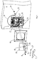
- Fig. 1 shows the glass fiber junction box 1 according to the invention in an exploded view at a wall mounting location 2.
- This glass fiber junction box 1 comprises a housing part 3 facing the wall mounting location 2 and it is closed by means of a housing cover 4a, 4b in the form of a cover plate 4a and a cover frame 4b.
- the wall mounting station has a wall opening 16, from which a glass fiber reserve 13 protrudes, which is connected to the glass fiber connection box 1 and thus provides the glass fiber connection for a building via a first and a second plug 14 on the housing part 3.
- the wall mounting station 2 has a dowel 10 which — as will be described below — fixes the glass fiber junction box 1 according to the invention to the wall mounting station.
- first fastening means 5 in the form of a screw 5
- this cover plate 4a and the associated cover frame 4b on the housing part 3, which has a thread 18 are screwed to it through a first through hole 20 in the cover plate 4a, and specifically before the glass fiber connection box 1 at the wall mounting station 2 is attached.
- second fastening means 6, also in the form of a screw 6 the closed glass fiber junction box 1 is screwed to the dowel 10 at the wall mounting location, namely through a second through hole 21 in the cover plate 4a, then through the cover frame 4b and through a through hole 17 in the housing part 3 to the dowel 10.
- the first fastening means 5 is covered by a labeling device 7, comprising a labeling window 8 and a labeling element 9, with which this first fastening means 5 is then hidden on the glass fiber junction box 1 according to the invention and only the second fastening means 6 on the outside Glass fiber junction box 1 is visible and can therefore be operated.
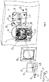
- Fig. 2 discloses an embodiment of the invention Fig. 1 with the difference that the glass fiber junction box 1 is not arranged directly at the wall mounting location 2, but is fixed indirectly to the wall mounting location 2 via an intermediate mounting plate 12.
- the fastening plate 12 is fastened by means of a screw 19 to a dowel 15 of the wall mounting location 2, the fastening plate 12 having a thread 11 which interacts with the second fastening means 6.
- the first fastening means 5 connects the closed glass fiber junction box 1 from the outside through the second through hole 21 on the cover plate 4a, through the cover frame 4b and the through hole 17 in the housing part 3 the glass fiber junction box 1 with the thread 11 of the fastening plate 12, which is arranged at the wall mounting place 2.
- FIG. 3 A further embodiment of the invention is shown, the glass fiber junction box 1 being different from the illustration in FIG Fig. 1 by the housing cover 4c, 4d in the form of an outer cover 4c and an inner cover 4d.
- the inner cover 4d is screwed by means of the first fastening means 5 through a through hole 22 of the inner cover 4d and through the through hole 17 of the housing part 3 with dowels 10, whereby the glass fiber junction box 1 is completely closed and protection against dirt and damage is effected .
- this first fastening means 5 in the form of the screw 5
- this first fastening means 5 in the form of a snap-in connection between the housing part 3 and the inner cover 4d.
- the outer cover 4c has a through hole 24 through which the closed glass fiber junction box 1 is screwed with a thread by means of the second fastening means 6 to a receiving bore 23 on the inner cover 4d. Furthermore, the outer cover 4c has the inscription device 7 with an inscription window 8 and a inscription element 9, the first fastening means 5 arranged on the inside of the inner cover 4d being covered by the inscription device 7 and only the second fastening means 6 being visible and operable from the outside .
- the embodiment of the glass fiber junction box 1 in Fig. 4 differs from the embodiment in Fig. 3 only in that the Glass fiber junction box 1 is not directly connected to the wall mounting place 2, but indirectly via the mounting plate 12, as already in connection with the Fig. 2 was discussed.
- the fastening plate 12 is screwed to the dowel 15 of the wall mounting location 2 with the screw 19.
- the inner cover 4d is screwed through the through hole 22 to the fastening plate 12 and the closed glass fiber junction box 1 is covered by the outer cover 4c
- the outer cover 4c by means of the second fastening means 6 through the through hole 24 in this outer cover 4c is screwed to a receiving bore 23 with a thread on the inner cover 4d.
- the glass fiber junction box 1 according to the invention can be temporarily removed from the wall mounting station 2 in one piece and closed, so that the contents of the glass fiber junction box 1 are completely protected against dirt and damage in the state separated from the wall mounting station 2 .
- Only the separation of the two functions, namely the closing of the fiber optic junction box 1 with the first fastening means 5, or the assembly of the closed fiber optic junction box 1 at the wall mounting location 2 with the second fastening means 6, enables the contents of the fiber optic junction box 1 to be fully protected, and this both with an initial installation as well as with a subsequent disassembly and reinstallation.
Landscapes
- Physics & Mathematics (AREA)
- Engineering & Computer Science (AREA)
- Civil Engineering (AREA)
- Structural Engineering (AREA)
- General Physics & Mathematics (AREA)
- Optics & Photonics (AREA)
- Architecture (AREA)
- Connection Or Junction Boxes (AREA)
- Light Guides In General And Applications Therefor (AREA)
Applications Claiming Priority (1)
| Application Number | Priority Date | Filing Date | Title |
|---|---|---|---|
| CH001147/2018A CH715372B1 (de) | 2018-09-21 | 2018-09-21 | Glasfaseranschlussdose für eine Wandmontage an einem Wandmontageplatz in einem Gebäude. |
Publications (1)
| Publication Number | Publication Date |
|---|---|
| EP3627202A1 true EP3627202A1 (fr) | 2020-03-25 |
Family
ID=68062809
Family Applications (1)
| Application Number | Title | Priority Date | Filing Date |
|---|---|---|---|
| EP19198093.7A Withdrawn EP3627202A1 (fr) | 2018-09-21 | 2019-09-18 | Boîtier de raccordement en fibre de verre |
Country Status (2)
| Country | Link |
|---|---|
| EP (1) | EP3627202A1 (fr) |
| CH (1) | CH715372B1 (fr) |
Citations (3)
| Publication number | Priority date | Publication date | Assignee | Title |
|---|---|---|---|---|
| JP2004157263A (ja) * | 2002-11-05 | 2004-06-03 | Sumitomo Electric Ind Ltd | アウトレット |
| EP2230738A2 (fr) | 2009-03-19 | 2010-09-22 | Zidatech AG | Boîte saillie |
| US20100310222A1 (en) * | 2007-09-28 | 2010-12-09 | Junsheng Zhou | Splice holder for communication socket |
-
2018
- 2018-09-21 CH CH001147/2018A patent/CH715372B1/de unknown
-
2019
- 2019-09-18 EP EP19198093.7A patent/EP3627202A1/fr not_active Withdrawn
Patent Citations (3)
| Publication number | Priority date | Publication date | Assignee | Title |
|---|---|---|---|---|
| JP2004157263A (ja) * | 2002-11-05 | 2004-06-03 | Sumitomo Electric Ind Ltd | アウトレット |
| US20100310222A1 (en) * | 2007-09-28 | 2010-12-09 | Junsheng Zhou | Splice holder for communication socket |
| EP2230738A2 (fr) | 2009-03-19 | 2010-09-22 | Zidatech AG | Boîte saillie |
Also Published As
| Publication number | Publication date |
|---|---|
| CH715372B1 (de) | 2023-08-31 |
| CH715372A2 (de) | 2020-03-31 |
Similar Documents
| Publication | Publication Date | Title |
|---|---|---|
| EP3042423B1 (fr) | Boîtier de connecteur enfichable | |
| DE202013102583U1 (de) | Tür-Anordnung | |
| DE102012203394A1 (de) | Anschlussblock für Sanitärarmaturen | |
| DE102005043922A1 (de) | Tragbarer Behälter, insbesondere für professionelles Gerät und Instrumente | |
| EP3472415B1 (fr) | Système de charnière | |
| EP3627202A1 (fr) | Boîtier de raccordement en fibre de verre | |
| DE69208814T2 (de) | Haltevorrichtung für den Schlüssel eines Schlosses | |
| DE102016116518A1 (de) | Halteadapter für die Fixierung von Befehls- und Meldegeräten sowie Anordnung | |
| DE19600260C1 (de) | Innenscharnier zur Unterbringung im Verschraubungskanal von Gehäusen | |
| DE10230622B4 (de) | Tülle zum Durchführen und Halten länglicher Objekte | |
| DE102019128325B3 (de) | Scharnier | |
| DE102018221627A1 (de) | Kabeldurchführung für einen Durchbruch in einer Platte | |
| DE20000777U1 (de) | Geräteeinbaudose für Leitungsführungskanäle | |
| CH713572A2 (de) | Installationsdose für elektrische Anschlüsse. | |
| DE19842512C1 (de) | Anordnung zur Installation einer Einbaukomponente in eine Wandung oder einen Hohlkörper | |
| DE10327267A1 (de) | Notentriegelungsvorrichtung | |
| DE102005032361B4 (de) | Betätigungsvorrichtung für ein Türblatt einer Duschkabine | |
| DE10153709A1 (de) | Kabelkanalübergang zwischen einem Türflügel und einer Türzarge | |
| DE102021004837B4 (de) | Aufnahme- und Festlegevorrichtung, System, Schaltschrank und Anschlusssystem | |
| EP3716427B1 (fr) | Plaque de bride pour le montage dans une percée d'une paroi de boîtier | |
| DE19830139B4 (de) | Schlüsselschaltervorrichtung | |
| EP3211160B1 (fr) | Rosette | |
| DE202023104058U1 (de) | Werkzeuglos austauschbare Haltevorrichtung | |
| DE29904377U1 (de) | Türbeschlag | |
| DE102020134152A1 (de) | Schaltschrankanordnung |
Legal Events
| Date | Code | Title | Description |
|---|---|---|---|
| PUAI | Public reference made under article 153(3) epc to a published international application that has entered the european phase |
Free format text: ORIGINAL CODE: 0009012 |
|
| STAA | Information on the status of an ep patent application or granted ep patent |
Free format text: STATUS: THE APPLICATION HAS BEEN PUBLISHED |
|
| AK | Designated contracting states |
Kind code of ref document: A1 Designated state(s): AL AT BE BG CH CY CZ DE DK EE ES FI FR GB GR HR HU IE IS IT LI LT LU LV MC MK MT NL NO PL PT RO RS SE SI SK SM TR |
|
| AX | Request for extension of the european patent |
Extension state: BA ME |
|
| STAA | Information on the status of an ep patent application or granted ep patent |
Free format text: STATUS: THE APPLICATION IS DEEMED TO BE WITHDRAWN |
|
| 18D | Application deemed to be withdrawn |
Effective date: 20200926 |