EP2230738A2 - Boîte saillie - Google Patents
Boîte saillie Download PDFInfo
- Publication number
- EP2230738A2 EP2230738A2 EP10405046A EP10405046A EP2230738A2 EP 2230738 A2 EP2230738 A2 EP 2230738A2 EP 10405046 A EP10405046 A EP 10405046A EP 10405046 A EP10405046 A EP 10405046A EP 2230738 A2 EP2230738 A2 EP 2230738A2
- Authority
- EP
- European Patent Office
- Prior art keywords
- housing
- box according
- mounted box
- cover
- opening
- Prior art date
- Legal status (The legal status is an assumption and is not a legal conclusion. Google has not performed a legal analysis and makes no representation as to the accuracy of the status listed.)
- Withdrawn
Links
- 230000008878 coupling Effects 0.000 claims abstract description 15
- 238000010168 coupling process Methods 0.000 claims abstract description 15
- 238000005859 coupling reaction Methods 0.000 claims abstract description 15
- 230000037431 insertion Effects 0.000 claims description 13
- 238000003780 insertion Methods 0.000 claims description 13
- 230000001681 protective effect Effects 0.000 claims description 13
- 238000006073 displacement reaction Methods 0.000 claims description 4
- 239000000835 fiber Substances 0.000 claims description 4
- 238000005192 partition Methods 0.000 description 3
- 229910052751 metal Inorganic materials 0.000 description 2
- 239000002184 metal Substances 0.000 description 2
- 210000003462 vein Anatomy 0.000 description 2
- 240000006829 Ficus sundaica Species 0.000 description 1
- 229910052782 aluminium Inorganic materials 0.000 description 1
- XAGFODPZIPBFFR-UHFFFAOYSA-N aluminium Chemical compound [Al] XAGFODPZIPBFFR-UHFFFAOYSA-N 0.000 description 1
- 230000015572 biosynthetic process Effects 0.000 description 1
- 150000001875 compounds Chemical class 0.000 description 1
- 230000005489 elastic deformation Effects 0.000 description 1
- 239000003365 glass fiber Substances 0.000 description 1
- 238000001746 injection moulding Methods 0.000 description 1
- 230000003287 optical effect Effects 0.000 description 1
- 230000001012 protector Effects 0.000 description 1
- 238000004804 winding Methods 0.000 description 1
Images
Classifications
-
- G—PHYSICS
- G02—OPTICS
- G02B—OPTICAL ELEMENTS, SYSTEMS OR APPARATUS
- G02B6/00—Light guides; Structural details of arrangements comprising light guides and other optical elements, e.g. couplings
- G02B6/46—Processes or apparatus adapted for installing or repairing optical fibres or optical cables
- G02B6/47—Installation in buildings
- G02B6/475—Mechanical aspects of installing cables in ducts or the like for buildings
-
- G—PHYSICS
- G02—OPTICS
- G02B—OPTICAL ELEMENTS, SYSTEMS OR APPARATUS
- G02B6/00—Light guides; Structural details of arrangements comprising light guides and other optical elements, e.g. couplings
- G02B6/44—Mechanical structures for providing tensile strength and external protection for fibres, e.g. optical transmission cables
- G02B6/4439—Auxiliary devices
- G02B6/444—Systems or boxes with surplus lengths
- G02B6/44528—Patch-cords; Connector arrangements in the system or in the box
-
- G—PHYSICS
- G02—OPTICS
- G02B—OPTICAL ELEMENTS, SYSTEMS OR APPARATUS
- G02B6/00—Light guides; Structural details of arrangements comprising light guides and other optical elements, e.g. couplings
- G02B6/46—Processes or apparatus adapted for installing or repairing optical fibres or optical cables
- G02B6/47—Installation in buildings
- G02B6/477—Wall sockets
-
- H—ELECTRICITY
- H02—GENERATION; CONVERSION OR DISTRIBUTION OF ELECTRIC POWER
- H02G—INSTALLATION OF ELECTRIC CABLES OR LINES, OR OF COMBINED OPTICAL AND ELECTRIC CABLES OR LINES
- H02G3/00—Installations of electric cables or lines or protective tubing therefor in or on buildings, equivalent structures or vehicles
- H02G3/02—Details
- H02G3/08—Distribution boxes; Connection or junction boxes
- H02G3/10—Distribution boxes; Connection or junction boxes for surface mounting on a wall
-
- H—ELECTRICITY
- H02—GENERATION; CONVERSION OR DISTRIBUTION OF ELECTRIC POWER
- H02G—INSTALLATION OF ELECTRIC CABLES OR LINES, OR OF COMBINED OPTICAL AND ELECTRIC CABLES OR LINES
- H02G3/00—Installations of electric cables or lines or protective tubing therefor in or on buildings, equivalent structures or vehicles
- H02G3/02—Details
- H02G3/08—Distribution boxes; Connection or junction boxes
- H02G3/14—Fastening of cover or lid to box
-
- H—ELECTRICITY
- H02—GENERATION; CONVERSION OR DISTRIBUTION OF ELECTRIC POWER
- H02G—INSTALLATION OF ELECTRIC CABLES OR LINES, OR OF COMBINED OPTICAL AND ELECTRIC CABLES OR LINES
- H02G11/00—Arrangements of electric cables or lines between relatively-movable parts
-
- H—ELECTRICITY
- H02—GENERATION; CONVERSION OR DISTRIBUTION OF ELECTRIC POWER
- H02G—INSTALLATION OF ELECTRIC CABLES OR LINES, OR OF COMBINED OPTICAL AND ELECTRIC CABLES OR LINES
- H02G3/00—Installations of electric cables or lines or protective tubing therefor in or on buildings, equivalent structures or vehicles
- H02G3/02—Details
- H02G3/08—Distribution boxes; Connection or junction boxes
- H02G3/086—Assembled boxes
Definitions
- the invention relates to a surface-mounted box, as they are used, especially in private households, as junction boxes for fiber optic connections.
- the invention is based on the object to form a generic surface-mounted box such that a component containing all the essential elements thereof is easily removable from the wall and re-attachable.
- This object is solved by the features in the characterizing part of claim 1.
- a housing of the inventive surface-mounted box can be removed after removing a cover and releasing a locking connection and placed again after making the desired changes, locked and closed. In this way, the said changes are quick and easy to carry out and the risk of errors is lower.
- the surface-mounted box according to the invention once removed, is also freely accessible from the rear, which is e.g. can be used to provide space for a cable reserve here.
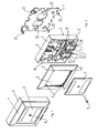
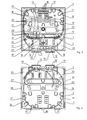
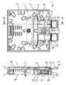
- the approximately square surface box or flat surface box comprises ( Fig. 1, 2 ) a mounting plate 1, a perforated stamped and bent part made of metal, usually aluminum, which can be screwed to a vertical wall and a connected to it housing 2 with a circumferential side wall 3.
- the housing 2 is open at a back and a front side, but the former rests against the mounting plate 1 while the latter is closed by a separate, removable cover.
- This comprises a cover frame 4, which leaves open a residual opening 5 and a cover plate 6, which closes them.
- the housing 2 has a parallel to the mounting plate 1, both spaced from the same and from the cover, multi-perforated partition 7.
- the surface-mounted box is held together by a bolt 8, the head in a sinking at the facing forward outside of the cover plate 6 and is screwed through the intermediate wall 7 through with the mounting plate 1.
- the cover 4 has at the corners of the remaining opening recessed stops 9, at which corner regions of the back of the cover plate 6 abut, so that the cover 4 is fixed.
- receptacles 10 are provided for couplings 11, which are accessible through connection openings 12 in the side wall 3.
- connection openings 12 In front of the connection openings 12, separate protective flaps 13 are mounted on the outside of the side wall 3 so as to be pivotable outwards, by means of which the receptacles 10 can be closed.
- the housing 2 and the cover and the protective flaps 13 are each made of plastic and are produced by injection molding.
- a duplex coupling shown each with two connector receptacles on the inside and at the connection opening 12 facing the outside, into which each plug 14 can be inserted.
- At the plug 14 on the inside in each case includes a wire 15, a jacketed glass fiber, which runs in one turn or several turns along the outside of a front reserve space 16 and thus forms a fiber reserve.
- a guide which is formed from formed on the intermediate wall 7 wall pieces and from the front edges thereof and the side wall 3 inwardly into the front reserve space 16 projecting retaining projections 17, held.
- brackets 18 for receiving a respective shrink sleeve splice protector 19 and four other brackets 18 'are formed for receiving a respective press splice protection. They are each as two in-line grooves or a continuous one Groove formed, which are each formed between two parallel, projecting from the front of the intermediate wall webs, which are thickened somewhat at their front edges.
- each of the wires 15 is connected to a wire 20.
- the wires 20 belong to a cable 21, the envelope of which is removed at an end portion. They also form a fiber reserve comprising at least one turn in the front reserve space 16.
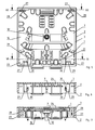
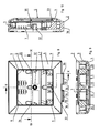
- the cable 21 is secured by means of a cable tie 22 to the intermediate wall 7 and comes through one of a plurality of openings 23, 23 'in the same from a rear reserve space 24 (FIG. Fig. 4 ), which lies between the intermediate wall 7 and the mounting plate 1.
- the cable 21 comes from a lying behind the mounting plate 1 opening in the wall from which it passes through one of two passages 25 (FIG. Fig. 2 ) in the mounting plate 1 in the rear reserve space 24, where it, by holding projections 17 ', which, spaced from the partition 7, projecting into the rear reserve space 24, held, forms a cable reserve, which consists of at least one on the inside of the side wall 2 continuous winding or more outwardly consecutive such turns before it reaches one of the openings 23.
- the cable may also be guided through an opening in the side wall 3 broken open at one of a plurality of predetermined breaking points 26 into the rear reserve space 24, in which case it runs in one turn or several turns inwards as far as one of the openings 23 'through which it is guided in the front reserve space 16.
- the second receptacle 10 may, as in Fig. 2 shown, also record a duplex coupling to which two more wires of another cable can be connected by means of plugs. Instead of a duplex coupling, however, in each case a simple coupling can be used, to which in each case only one core can be connected.
- the mounting plate 1 in each case an approximately rectangular projecting retaining tab 27, which is in each case in a closely surrounding recess 28 in the housing 2.
- approximately rectangular protruding locking tabs 29 are provided which project through two of the openings 23 in the intermediate wall 7 in the front reserve space 16 and carry at their ends against each other hook-like projections 30, each one of the side wall 2 into the interior of the front reserve space 16 projecting locking ridge 31 overlap.
- the same is suspended on the retaining tabs 27 by the recesses 28 are pushed over the same. Then, the lower end of the housing 2 is also pressed against the mounting plate 1, wherein the locking webs 31 are pressed by the locking tabs 29 against each other and then elastically return to their original position in which they are overlapped by the projections 30.
- the housing 2 is thus locked to the mounting plate 1.
- the cover can then be fixed by means of guided through a central passage 32 in the intermediate wall 7 bolt 8, the compound.
- the locking can be achieved by the locking webs 31 are bent against each other through the open front of the housing. The lower end of the housing 2 can then slightly swung away from the mounting plate 1 and finally the housing 2 are withdrawn from the retaining tabs 27.
- the cover frame 4 is located ( Fig. 8-10 ) only flat and outside flush on the front edge of the side wall 3. However, it is secured against rotation by projecting from the front of the intermediate wall 7, a central stop projection 33 and two lateral stop projections 34, 35 at right angles, abutting the tips of the inner edge of the remaining opening 5 on the cover 4 and thus form stops which form a rotation of the the latter and a displacement of the same upwards relative to the housing 2 prevent.
- one of the receptacles 10 contains a duplex coupling and the other a simple coupling.
- the simple coupling 11 has a sleeve 37 with an inner insertion opening 38 for receiving a plug 14 (FIG. Fig. 3 ), in which a cable 15 coming from the cable 21 terminates and an outer insertion opening 39 for receiving a plug (not shown) for establishing an optical connection of the wire 15 with a modem or another device.
- an inlet opening 40 of a coupler is arranged and at the bottom of the insertion opening 39, an outlet opening 41 of the same.
- an elastic protective plate 42 for example made of sheet metal, attached to the sleeve 37, in the edge region of the insertion opening 39 projecting obliquely against the outlet opening 41 and this concealing. If a plug is pushed into the insertion opening 39, it exerts a force directed against the outlet opening 41 on the protective plate 42, which then deflects under elastic deformation. If the plug is pulled out again, then the protective plate 42 returns to its original position and covers the outlet opening 41. Thus, a danger is prevented especially by children who may be tempted to open the protective flap 13 and from close proximity into the insertion opening 39 watch.
- a duplex coupling which has two couplers arranged next to one another in the sleeve, it is preferable to provide two protective plates, one for each of the two adjacent insertion openings. Also, instead of a protective flap two adjacent independently pivotable protective flaps can be provided.
- the surface-mount box can be modified in many ways without departing from the scope of the invention. Thus, it may have a different shape, e.g. be round or have other or additional connections, such as coaxial cable or twisted pair cable. It is also possible to form a generic box according to one of claims 7 to 9, 10 to 13 or claim 15, without making use of the characterizing features of claim 1.
Landscapes
- Physics & Mathematics (AREA)
- Engineering & Computer Science (AREA)
- Civil Engineering (AREA)
- Structural Engineering (AREA)
- General Physics & Mathematics (AREA)
- Optics & Photonics (AREA)
- Architecture (AREA)
- Light Guides In General And Applications Therefor (AREA)
- Details Of Connecting Devices For Male And Female Coupling (AREA)
- Connector Housings Or Holding Contact Members (AREA)
- Connection Or Junction Boxes (AREA)
Applications Claiming Priority (1)
| Application Number | Priority Date | Filing Date | Title |
|---|---|---|---|
| CH00416/09A CH700667B1 (de) | 2009-03-19 | 2009-03-19 | Aufputzdose. |
Publications (2)
| Publication Number | Publication Date |
|---|---|
| EP2230738A2 true EP2230738A2 (fr) | 2010-09-22 |
| EP2230738A3 EP2230738A3 (fr) | 2014-08-20 |
Family
ID=42358658
Family Applications (1)
| Application Number | Title | Priority Date | Filing Date |
|---|---|---|---|
| EP10405046.3A Withdrawn EP2230738A3 (fr) | 2009-03-19 | 2010-03-10 | Boîte saillie |
Country Status (2)
| Country | Link |
|---|---|
| EP (1) | EP2230738A3 (fr) |
| CH (1) | CH700667B1 (fr) |
Cited By (4)
| Publication number | Priority date | Publication date | Assignee | Title |
|---|---|---|---|---|
| US10261280B1 (en) * | 2018-05-23 | 2019-04-16 | Amphenol Fiber Optic Technology (Shenzhen) Co., Ltd. | Optical fiber distribution box |
| EP3627202A1 (fr) | 2018-09-21 | 2020-03-25 | Zidatech AG | Boîtier de raccordement en fibre de verre |
| WO2020247674A1 (fr) * | 2019-06-04 | 2020-12-10 | Ppc Broadband Fiber Ltd. | Boîtier d'enceinte pour câble à fibres optiques |
| EP4296740A1 (fr) * | 2022-06-23 | 2023-12-27 | Corning Research & Development Corporation | Sortie à fibre optique modulaire |
Families Citing this family (1)
| Publication number | Priority date | Publication date | Assignee | Title |
|---|---|---|---|---|
| USD816035S1 (en) | 2015-11-13 | 2018-04-24 | Panduit Corp. | Surface mount box |
Family Cites Families (2)
| Publication number | Priority date | Publication date | Assignee | Title |
|---|---|---|---|---|
| ES2252114T3 (es) * | 1995-02-02 | 2006-05-16 | The Wiremold Company | Caja de conexion electrica. |
| EP2006966A1 (fr) * | 2007-06-22 | 2008-12-24 | C & C Marshall Limited | Système de distribution électrique et de service |
-
2009
- 2009-03-19 CH CH00416/09A patent/CH700667B1/de unknown
-
2010
- 2010-03-10 EP EP10405046.3A patent/EP2230738A3/fr not_active Withdrawn
Non-Patent Citations (1)
| Title |
|---|
| None |
Cited By (6)
| Publication number | Priority date | Publication date | Assignee | Title |
|---|---|---|---|---|
| US10261280B1 (en) * | 2018-05-23 | 2019-04-16 | Amphenol Fiber Optic Technology (Shenzhen) Co., Ltd. | Optical fiber distribution box |
| EP3627202A1 (fr) | 2018-09-21 | 2020-03-25 | Zidatech AG | Boîtier de raccordement en fibre de verre |
| WO2020247674A1 (fr) * | 2019-06-04 | 2020-12-10 | Ppc Broadband Fiber Ltd. | Boîtier d'enceinte pour câble à fibres optiques |
| US11397300B2 (en) | 2019-06-04 | 2022-07-26 | Ppc Broadband Fiber Ltd. | Enclosure box for fiber optic cable |
| US12259589B2 (en) | 2019-06-04 | 2025-03-25 | Ppc Broadband Fiber Ltd. | Enclosure box for fiber optic cable |
| EP4296740A1 (fr) * | 2022-06-23 | 2023-12-27 | Corning Research & Development Corporation | Sortie à fibre optique modulaire |
Also Published As
| Publication number | Publication date |
|---|---|
| EP2230738A3 (fr) | 2014-08-20 |
| CH700667B1 (de) | 2017-10-13 |
| CH700667A2 (de) | 2010-09-30 |
Similar Documents
| Publication | Publication Date | Title |
|---|---|---|
| DE19860812B4 (de) | Kabelkanalsystem zum Verlegen von Lichtwellenleiterkabeln | |
| EP2450729B1 (fr) | Système modulaire pour un dispositif de fixation | |
| DE60133336T2 (de) | Kabelkanal mit geteilter Abdeckung | |
| DE102009005370B4 (de) | Elektrisches Verteilergehäuse für Kraftfahrzeuge | |
| EP2230738A2 (fr) | Boîte saillie | |
| EP2241917A2 (fr) | Boîte de branchement | |
| EP1039632B1 (fr) | Absorbeur électrique de bruit et procédé de montage à un cable | |
| DE202009005462U1 (de) | Aufputzdose | |
| DE3842205C2 (de) | Gehäuse für den Anschluß von Kommunikationssystemen | |
| DE10003922C2 (de) | Einbaudose zur Verwendung in einem Kabelkanal, wie Brüstungskanal | |
| DE29922165U1 (de) | Anschlußdosenanordnung für Lichtwellenleiterkabel | |
| DE102004013010B3 (de) | Vorrichtung zur Aufnahme von länglichen Gegenständen | |
| DE4290308C2 (de) | Kasten für automatische Sicherungen | |
| DE3500655A1 (de) | Gehaeuse fuer verteiler, insbesondere fuer fernsprechanlagen | |
| EP0062135A2 (fr) | Armoire étanche aux projections d'eau pour appareils électriques tels que des automates, des fusibles, des bornes, des compteurs électriques et analogues | |
| DE29904357U1 (de) | Installationsdose für Lichtwellenleiter | |
| DE9308110U1 (de) | Kabelanschlußkasten | |
| DE8409752U1 (de) | Sockelleisten-Installationskanal | |
| DE102018102168A1 (de) | Elektrizitätszähler mit einer optischen Kommunikationsschnittstelle | |
| DE3717776C2 (de) | Einbaudose, insbesondere Unterputzdose | |
| DE9211603U1 (de) | Anschlußkasten | |
| EP0520314A1 (fr) | Tube de connexion pour boîtiers pour murs à cavité | |
| DE464739C (de) | Befestigungsvorrichtung an Kondensatorgehaeusen, insbesondere an Gehaeusen aus Pappe, Pressspan, Papiermache u. dgl. | |
| DE20102260U1 (de) | Modulares Verteilersystem für optische Kabel | |
| DE8712359U1 (de) | Spulenkörper |
Legal Events
| Date | Code | Title | Description |
|---|---|---|---|
| PUAI | Public reference made under article 153(3) epc to a published international application that has entered the european phase |
Free format text: ORIGINAL CODE: 0009012 |
|
| AK | Designated contracting states |
Kind code of ref document: A2 Designated state(s): AT BE BG CH CY CZ DE DK EE ES FI FR GB GR HR HU IE IS IT LI LT LU LV MC MK MT NL NO PL PT RO SE SI SK SM TR |
|
| AX | Request for extension of the european patent |
Extension state: AL BA ME RS |
|
| RIC1 | Information provided on ipc code assigned before grant |
Ipc: H02G 11/00 20060101ALN20140217BHEP Ipc: H02G 3/10 20060101AFI20140217BHEP Ipc: H02G 3/08 20060101ALN20140217BHEP Ipc: H02G 3/14 20060101ALN20140217BHEP Ipc: G02B 6/44 20060101ALI20140217BHEP |
|
| PUAL | Search report despatched |
Free format text: ORIGINAL CODE: 0009013 |
|
| AK | Designated contracting states |
Kind code of ref document: A3 Designated state(s): AT BE BG CH CY CZ DE DK EE ES FI FR GB GR HR HU IE IS IT LI LT LU LV MC MK MT NL NO PL PT RO SE SI SK SM TR |
|
| AX | Request for extension of the european patent |
Extension state: AL BA ME RS |
|
| RIC1 | Information provided on ipc code assigned before grant |
Ipc: H02G 3/10 20060101AFI20140717BHEP Ipc: H02G 3/08 20060101ALN20140717BHEP Ipc: H02G 3/14 20060101ALN20140717BHEP Ipc: G02B 6/44 20060101ALI20140717BHEP Ipc: H02G 11/00 20060101ALN20140717BHEP |
|
| STAA | Information on the status of an ep patent application or granted ep patent |
Free format text: STATUS: THE APPLICATION IS DEEMED TO BE WITHDRAWN |
|
| 18D | Application deemed to be withdrawn |
Effective date: 20141001 |