EP3627645B1 - Convertisseur - Google Patents
Convertisseur Download PDFInfo
- Publication number
- EP3627645B1 EP3627645B1 EP19192472.9A EP19192472A EP3627645B1 EP 3627645 B1 EP3627645 B1 EP 3627645B1 EP 19192472 A EP19192472 A EP 19192472A EP 3627645 B1 EP3627645 B1 EP 3627645B1
- Authority
- EP
- European Patent Office
- Prior art keywords
- converter
- series
- link capacitor
- midpoint
- switches
- Prior art date
- Legal status (The legal status is an assumption and is not a legal conclusion. Google has not performed a legal analysis and makes no representation as to the accuracy of the status listed.)
- Active
Links
Images

Classifications
-
- H—ELECTRICITY
- H02—GENERATION; CONVERSION OR DISTRIBUTION OF ELECTRIC POWER
- H02H—EMERGENCY PROTECTIVE CIRCUIT ARRANGEMENTS
- H02H7/00—Emergency protective circuit arrangements specially adapted for specific types of electric machines or apparatus or for sectionalised protection of cable or line systems, and effecting automatic switching in the event of an undesired change from normal working conditions
- H02H7/06—Emergency protective circuit arrangements specially adapted for specific types of electric machines or apparatus or for sectionalised protection of cable or line systems, and effecting automatic switching in the event of an undesired change from normal working conditions for dynamo-electric generators; for synchronous capacitors
-
- H—ELECTRICITY
- H02—GENERATION; CONVERSION OR DISTRIBUTION OF ELECTRIC POWER
- H02M—APPARATUS FOR CONVERSION BETWEEN AC AND AC, BETWEEN AC AND DC, OR BETWEEN DC AND DC, AND FOR USE WITH MAINS OR SIMILAR POWER SUPPLY SYSTEMS; CONVERSION OF DC OR AC INPUT POWER INTO SURGE OUTPUT POWER; CONTROL OR REGULATION THEREOF
- H02M7/00—Conversion of AC power input into DC power output; Conversion of DC power input into AC power output
- H02M7/02—Conversion of AC power input into DC power output without possibility of reversal
- H02M7/04—Conversion of AC power input into DC power output without possibility of reversal by static converters
- H02M7/12—Conversion of AC power input into DC power output without possibility of reversal by static converters using discharge tubes with control electrode or semiconductor devices with control electrode
- H02M7/21—Conversion of AC power input into DC power output without possibility of reversal by static converters using discharge tubes with control electrode or semiconductor devices with control electrode using devices of a triode or transistor type requiring continuous application of a control signal
- H02M7/217—Conversion of AC power input into DC power output without possibility of reversal by static converters using discharge tubes with control electrode or semiconductor devices with control electrode using devices of a triode or transistor type requiring continuous application of a control signal using semiconductor devices only
- H02M7/2173—Conversion of AC power input into DC power output without possibility of reversal by static converters using discharge tubes with control electrode or semiconductor devices with control electrode using devices of a triode or transistor type requiring continuous application of a control signal using semiconductor devices only in a biphase or polyphase circuit arrangement
-
- H—ELECTRICITY
- H02—GENERATION; CONVERSION OR DISTRIBUTION OF ELECTRIC POWER
- H02H—EMERGENCY PROTECTIVE CIRCUIT ARRANGEMENTS
- H02H7/00—Emergency protective circuit arrangements specially adapted for specific types of electric machines or apparatus or for sectionalised protection of cable or line systems, and effecting automatic switching in the event of an undesired change from normal working conditions
- H02H7/10—Emergency protective circuit arrangements specially adapted for specific types of electric machines or apparatus or for sectionalised protection of cable or line systems, and effecting automatic switching in the event of an undesired change from normal working conditions for converters; for rectifiers
- H02H7/12—Emergency protective circuit arrangements specially adapted for specific types of electric machines or apparatus or for sectionalised protection of cable or line systems, and effecting automatic switching in the event of an undesired change from normal working conditions for converters; for rectifiers for static converters or rectifiers
- H02H7/125—Emergency protective circuit arrangements specially adapted for specific types of electric machines or apparatus or for sectionalised protection of cable or line systems, and effecting automatic switching in the event of an undesired change from normal working conditions for converters; for rectifiers for static converters or rectifiers for rectifiers
-
- H—ELECTRICITY
- H02—GENERATION; CONVERSION OR DISTRIBUTION OF ELECTRIC POWER
- H02M—APPARATUS FOR CONVERSION BETWEEN AC AND AC, BETWEEN AC AND DC, OR BETWEEN DC AND DC, AND FOR USE WITH MAINS OR SIMILAR POWER SUPPLY SYSTEMS; CONVERSION OF DC OR AC INPUT POWER INTO SURGE OUTPUT POWER; CONTROL OR REGULATION THEREOF
- H02M7/00—Conversion of AC power input into DC power output; Conversion of DC power input into AC power output
- H02M7/02—Conversion of AC power input into DC power output without possibility of reversal
- H02M7/04—Conversion of AC power input into DC power output without possibility of reversal by static converters
- H02M7/12—Conversion of AC power input into DC power output without possibility of reversal by static converters using discharge tubes with control electrode or semiconductor devices with control electrode
- H02M7/21—Conversion of AC power input into DC power output without possibility of reversal by static converters using discharge tubes with control electrode or semiconductor devices with control electrode using devices of a triode or transistor type requiring continuous application of a control signal
- H02M7/217—Conversion of AC power input into DC power output without possibility of reversal by static converters using discharge tubes with control electrode or semiconductor devices with control electrode using devices of a triode or transistor type requiring continuous application of a control signal using semiconductor devices only
- H02M7/23—Conversion of AC power input into DC power output without possibility of reversal by static converters using discharge tubes with control electrode or semiconductor devices with control electrode using devices of a triode or transistor type requiring continuous application of a control signal using semiconductor devices only arranged for operation in parallel
-
- H—ELECTRICITY
- H02—GENERATION; CONVERSION OR DISTRIBUTION OF ELECTRIC POWER
- H02M—APPARATUS FOR CONVERSION BETWEEN AC AND AC, BETWEEN AC AND DC, OR BETWEEN DC AND DC, AND FOR USE WITH MAINS OR SIMILAR POWER SUPPLY SYSTEMS; CONVERSION OF DC OR AC INPUT POWER INTO SURGE OUTPUT POWER; CONTROL OR REGULATION THEREOF
- H02M7/00—Conversion of AC power input into DC power output; Conversion of DC power input into AC power output
- H02M7/02—Conversion of AC power input into DC power output without possibility of reversal
- H02M7/04—Conversion of AC power input into DC power output without possibility of reversal by static converters
- H02M7/12—Conversion of AC power input into DC power output without possibility of reversal by static converters using discharge tubes with control electrode or semiconductor devices with control electrode
- H02M7/21—Conversion of AC power input into DC power output without possibility of reversal by static converters using discharge tubes with control electrode or semiconductor devices with control electrode using devices of a triode or transistor type requiring continuous application of a control signal
- H02M7/217—Conversion of AC power input into DC power output without possibility of reversal by static converters using discharge tubes with control electrode or semiconductor devices with control electrode using devices of a triode or transistor type requiring continuous application of a control signal using semiconductor devices only
- H02M7/25—Conversion of AC power input into DC power output without possibility of reversal by static converters using discharge tubes with control electrode or semiconductor devices with control electrode using devices of a triode or transistor type requiring continuous application of a control signal using semiconductor devices only arranged for operation in series, e.g. for multiplication of voltage
-
- H—ELECTRICITY
- H02—GENERATION; CONVERSION OR DISTRIBUTION OF ELECTRIC POWER
- H02M—APPARATUS FOR CONVERSION BETWEEN AC AND AC, BETWEEN AC AND DC, OR BETWEEN DC AND DC, AND FOR USE WITH MAINS OR SIMILAR POWER SUPPLY SYSTEMS; CONVERSION OF DC OR AC INPUT POWER INTO SURGE OUTPUT POWER; CONTROL OR REGULATION THEREOF
- H02M7/00—Conversion of AC power input into DC power output; Conversion of DC power input into AC power output
- H02M7/42—Conversion of DC power input into AC power output without possibility of reversal
- H02M7/44—Conversion of DC power input into AC power output without possibility of reversal by static converters
- H02M7/48—Conversion of DC power input into AC power output without possibility of reversal by static converters using discharge tubes with control electrode or semiconductor devices with control electrode
- H02M7/483—Converters with outputs that each can have more than two voltages levels
- H02M7/487—Neutral point clamped inverters
-
- H—ELECTRICITY
- H02—GENERATION; CONVERSION OR DISTRIBUTION OF ELECTRIC POWER
- H02M—APPARATUS FOR CONVERSION BETWEEN AC AND AC, BETWEEN AC AND DC, OR BETWEEN DC AND DC, AND FOR USE WITH MAINS OR SIMILAR POWER SUPPLY SYSTEMS; CONVERSION OF DC OR AC INPUT POWER INTO SURGE OUTPUT POWER; CONTROL OR REGULATION THEREOF
- H02M1/00—Details of apparatus for conversion
- H02M1/32—Means for protecting converters other than automatic disconnection
Definitions
- This disclosure concerns electrical converters, which will be understood as embracing rectifiers and inverters.
- Permanent magnet electrical generators are used for their high efficiency and high power density. Their output is often supplied to a rectifier to produce a direct current output.
- the invention is directed towards an electrical converter and methods of operation therefor.
- an electrical converter having an active diode-clamped multilevel topology in which each clamping diode is connected in antiparallel with a switch.
- the converter comprises polyphase supply phases each of which are connected via a respective phase leg to dc rails and a dc-link capacitor.
- the dc-link capacitor including a plurality of series-connected capacitors.
- a method of controlling such a converter comprising, for each phase leg, activates a combination of switches therein to form a pair of parallel conduction paths to a midpoint between two capacitors in the dc-link capacitor, thereby connecting each phase to the same node.
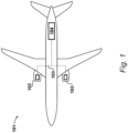
- FIG. 1 An example application of an embodiment is illustrated in Figure 1 .
- An aircraft 101 is shown in which a series-hybrid propulsion system is employed.
- a pair of electric propulsion units 102 are installed below the wings of the aircraft 101.
- the electric propulsion units 102 are connected via a power distribution bus 103 to a source of electrical power located in the fuselage of the aircraft 101.
- the source of electrical power is an internal combustion engine configured to drive an electric machine.
- the source of electrical power is turboelectric generator 104, in which the internal combustion engine is a gas turbine engine.
- the internal combustion engine may be a piston engine or similar.
- the source of electrical power could alternatively by a fuel cell, battery, etc.
- Each electric propulsion unit 102 includes an electric machine configured to drive a propulsive fan.
- the electric propulsion units 102 are ducted fans, although it will be appreciated that in alternative embodiments the electric propulsion units 102 may be configured as open propellers (a type of propulsive fan), or any other configuration able to produce thrust by causing a pressure rise in the incident airflow.
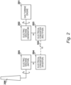
- Figure 2 is a block diagram of the propulsion system of the aircraft of Figure 1 .
- a gas turbine engine 201 drives a first machine 202 operating as a generator via an interconnecting shaft, thus providing a source of electrical power in the form of alternating current.
- the alternating current is converted to direct current for distribution on the bus by way of a first electrical converter 203 operating as a rectifier.
- Power is drawn from the bus 103 by a second electrical converter 204 operating as an inverter for supplying a second electric machine 205, which operates as a motor. This in turn drives a propulsive fan 206 via an interconnecting shaft, thereby providing propulsion.
- a second electrical converter 204 operating as an inverter for supplying a second electric machine 205, which operates as a motor.
- This in turn drives a propulsive fan 206 via an interconnecting shaft, thereby providing propulsion.
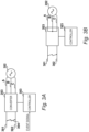
- FIGs 3A and 3B illustrate the approach adopted by the present embodiment of the electrical converter 203.
- the electric machine 202 is connected to the converter 203 via a polyphase supply.
- three phases A, B, C are connected with the converter. Being a polyphase supply, each phase is 120 degrees out-of-phase with the other two.
- the converter 203 is an active diode-clamped multilevel converter. Such a converter topology is substantially the same as a diode-clamped multilevel converter, except that the clamping diodes are connected in antiparallel with a switch to facilitate load sharing and thus prevent elevated temperatures.
- the topology of converter 203 will be described in further detail with reference to Figure 4 , and indeed such arrangements will be familiar to those skilled in the art.
- the converter 203 produces a dc output between a pair of dc rails 301 and 302.
- the converter 203 operates under the control of a controller 303, which in the present example is coupled with the switches in the converter 203 to generate a dc output from the polyphase supply.
- a controller 303 which in the present example is coupled with the switches in the converter 203 to generate a dc output from the polyphase supply.
- the controller 303 is a field-programmable gate array (FPGA) having been configured with appropriate control logic (e.g. a hardware description) to operate the converter 203.
- control logic e.g. a hardware description
- the controller 303 may instead be an application-specific integrated circuit or a microcontroller, etc.
- an event signal may be received by the controller 303.
- the generation of such event signals will be within the competence of those skilled in the art.
- the controller 303 is configured to, after receiving the event signal, enter the converter 203 into a crowbar mode of operation so as to isolate the electric machine 202 from the dc network.
- the crowbar mode of operation will be described further with reference to Figure 4 .
- the controller 303 may return the converter 203 to the normal mode of operation.
- FIG. 4 A circuit diagram of a specific embodiment of the converter 203 is shown in Figure 4 .
- the converter 203 has what is termed active diode-clamped multilevel topology.
- each clamping diode is connected in antiparallel with a switch.
- each switch in the converter 203 is provided by an insulated gate bipolar transistor (IGBT). This is due to the high levels of power produced by the electrical machine 202, which in the present embodiment is rated at 2.5 megawatts continuous for propulsion of the aircraft 101. It will be appreciated, however, that other transistors such as BJTs or MOSFETs, or indeed other types of switching devices may be used instead depending upon the intended application of the converter.
- the polyphase supply comprising phases A, B, and C are connected via a respective phase leg 401, 402, and 403 to the dc rails 301 and 302. It will be appreciated that other numbers of phases and phase legs may be implemented depending upon the configuration of the electric machine 202.
- converter 203 is a three-level converter, and so includes a dc-link capacitor comprising two series-connected capacitors 404 and 405.
- the midpoint 406 between the capacitors 404 and 405 is therefore a neutral point.
- the phase legs each include a plurality of switches composed of an IGBT-antiparallel diode pair, and which are labelled Snp, where n is the number of the switch and p is the attendant phase of the phase leg in which it is located, e.g. S1A is the upper outer IGBT-antiparallel diode pair in phase leg 401.
- Each leg includes four series-connected IGBT-antiparallel diode pairs ⁇ S1p ... S4p ⁇ , and two clamping IGBT-antiparallel diode pairs S5p and S6p.
- the controller 303 activates the required combination of switches ⁇ S1A ... S6C ⁇ to generate a dc output from the polyphase input.
- each leg has four possible combinations ⁇ 01 ... 04 ⁇ for connection of the phase to the neutral midpoint node 406.
- the well-established switch logic for this type of converter topology is set out in Table 1: Table 1 State S1p S2p S3p S4p S5p S6p + 1 1 0 0 0 1 01 0 1 0 0 1 0 02 0 1 0 1 1 0 03 1 0 1 0 0 0 1 04 0 0 1 0 0 1 - 0 0 1 1 1 0
- the electric machine 202 is optimised such that it exhibits an inductive impedance of 0.6 per-unit. Given a generated ac voltage of 1 per-unit, this would result in, unchecked, a fault current of 1.67 per-unit which would quickly cause thermal damage in the converter 203.
- the controller 303 activates a combination of switches in each phase leg 401, 402, and 403 that forms a pair of parallel conduction paths to the midpoint 406, as set out in Table 2:
- each phase A, B, C is connected to the same node and is thereby isolated from the dc network.
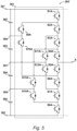
- FIG. 5 An alternative embodiment of the converter 203 is illustrated in Figure 5 , and is identified by reference numeral 203'. For simplicity, only one phase A and associated phase leg 501 is shown.
- the converter 203' has a five-level active diode-clamped topology and thus has a dc-link capacitor between the dc rails 301 and 302 that comprises four series-connected capacitors 502, 503, 504, 505. Three midpoints 506, 507, and 508 are therefore defined at the nodes between any adjacent two of the capacitors 502 to 505.
- phase leg 501 corresponding to phase A comprises a plurality of series-connected IGBT-antiparallel diode pairs ⁇ S1A ... S8A ⁇ which are connected between the dc rails 301 and 302.
- the connection with phase A is at a node between IGBT-antiparallel diode pairs S4A and S5A.
- Upper clamping IGBT-antiparallel diode pair S9A and S10A clamp to midpoint 506, neutral clamping IGBT-antiparallel diode pair S11A and S12A clamp to midpoint 507, and lower clamping IGBT-antiparallel diode pair S13A and S14A clamp to midpoint 508.
- This topology and its normal mode of operation will be understood by those skilled in the art and therefore will not be described further.
- the switching states C1, C2, and C3 are set out in Table 3: Table 3 State S1p S2p S3p S4p S5p S6p S7p S8p S9p S10p S11p S12p S13p S14p C1 0 1 1 1 1 0 0 0 1 1 0 0 0 0 C2 0 0 1 1 1 1 0 0 0 0 1 1 0 0 C3 0 0 0 1 1 1 1 0 0 0 0 0 1 1 1 1 1 0 0 0 0 1 1 1 1
- the controller 203 is configured to intermittently switch between the crowbar states C1, C2, and C3. This may be as part of a load balancing strategy. For example, the temperature in some of the activated IGBTs may after a certain time begin to exceed a threshold, for example due to conduction losses therein. In such a case, the present crowbar state, say C1, may be switched for another, say C2 or C3. Such a decision may be taken based upon the temperature of the devices to be activated in the other states (C2 or C3 in this example).
Landscapes
- Engineering & Computer Science (AREA)
- Power Engineering (AREA)
- Inverter Devices (AREA)
Claims (10)
- Convertisseur électrique (203) comportant une topologie multiniveau à diode active bloquée où chaque diode de blocage (S5P, S6P) est raccordée en antiparallèle à un commutateur (S5A, S5B), le convertisseur comprenant :
des phases d'alimentation polyphasées (A, B, C) dont chacune est raccordée par l'intermédiaire d'une branche de phase respective (401, 402, 403) à des rails CC (301, 302) et à un condensateur de liaison CC, le condensateur de liaison CC comprenant une pluralité de condensateurs raccordés en série (404, 405) ; et caractérisé par :
un dispositif de commande (303) configuré pour, en réponse à un signal d'événement indiquant un défaut qui s'est produit sur un côté CC du convertisseur, pour chaque branche de phase, activer une combinaison de commutateurs à l'intérieur de celui-ci pour former une paire de chemins de conduction parallèles vers un point médian (406) entre deux condensateurs dans le condensateur de liaison CC, raccordant ainsi chaque phase au même nœud et isolant une entrée du convertisseur du côté CC du convertisseur. - Convertisseur électrique de la revendication 1, comportant trois phases d'alimentation (A, B, C) et trois branches de phase (401, 402, 403).
- Convertisseur électrique de la revendication 1, où la topologie multiniveau est une topologie à trois niveaux, dans lequel le condensateur de liaison CC comprend deux condensateurs raccordés en série (404, 405) de sorte que le point médian (406) est un nœud entre les deux condensateurs raccordés en série.
- Convertisseur électrique de la revendication 1, où la topologie multiniveau est au moins une topologie à quatre niveaux, dans lequel le condensateur de liaison CC comprend trois condensateurs ou plus raccordés en série (502, 503, 504, 505) de sorte que le point médian (506, 507, 508) est un nœud entre deux condensateurs adjacents parmi les trois condensateurs ou plus raccordés en série.
- Convertisseur électrique de la revendication 4, où le dispositif de commande (303) est configuré pour, pour chaque branche de phase (501), changer par intermittence entre des combinaisons de commutateurs pour former différentes paires de chemins de conduction parallèles vers différents points médians (506, 507, 508).
- Convertisseur électrique de la revendication 5, où le dispositif de commande (303) est configuré pour changer entre des combinaisons de commutateurs en réponse au dépassement, par une température d'au moins un des commutateurs, d'une valeur seuil.
- Procédé de fonctionnement d'un convertisseur électrique (203) du type comportant une topologie multiniveau à diode active bloquée où chaque diode de blocage (S5P, S6P) est raccordée en antiparallèle à un commutateur (S5A, S5B), et des phases d'alimentation polyphasées (A, B, C) dont chacune est raccordée par l'intermédiaire d'une branche de phase respective (401, 402, 403) à des rails CC (301, 302) et à un condensateur de liaison CC, le condensateur de liaison CC comprenant une pluralité de condensateurs raccordés en série (404, 405) ;
le procédé comprenant, en réponse à un signal d'événement indiquant un défaut qui s'est produit sur un côté CC du convertisseur, pour chaque branche de phase (401, 402, 403) dans le convertisseur (203), l'activation d'une combinaison de commutateurs à l'intérieur de celui-ci pour former une paire de chemins de conduction parallèles vers un point médian (406) entre deux condensateurs dans le condensateur de liaison CC, raccordant ainsi chaque phase au même nœud et isolant une entrée du convertisseur du côté CC du convertisseur. - Procédé de la revendication 7, où la topologie multiniveau est une topologie à trois niveaux, dans lequel le condensateur de liaison CC comprend deux condensateurs raccordés en série (404, 405) de sorte que le point médian (406) est un nœud entre les deux condensateurs raccordés en série.
- Procédé de la revendication 7, où la topologie multiniveau est une topologie à quatre niveaux ou plus, dans lequel le condensateur de liaison CC comprend trois condensateurs ou plus raccordés en série (502, 503, 504, 505) de sorte que le point médian (506, 507, 508) est un nœud entre deux condensateurs adjacents parmi les trois condensateurs ou plus raccordés en série.
- Procédé de la revendication 9, comprenant en outre, pour chaque branche de phase (501), le changement intermittent entre des combinaisons de commutateurs pour former différentes paires de chemins de conduction parallèles vers différents points médians, éventuellement en réponse au dépassement, par une température d'au moins un des commutateurs, d'une valeur seuil (506, 507, 508).
Applications Claiming Priority (1)
| Application Number | Priority Date | Filing Date | Title |
|---|---|---|---|
| GBGB1815301.5A GB201815301D0 (en) | 2018-09-20 | 2018-09-20 | Converter |
Publications (2)
| Publication Number | Publication Date |
|---|---|
| EP3627645A1 EP3627645A1 (fr) | 2020-03-25 |
| EP3627645B1 true EP3627645B1 (fr) | 2025-02-19 |
Family
ID=64024353
Family Applications (1)
| Application Number | Title | Priority Date | Filing Date |
|---|---|---|---|
| EP19192472.9A Active EP3627645B1 (fr) | 2018-09-20 | 2019-08-20 | Convertisseur |
Country Status (4)
| Country | Link |
|---|---|
| US (1) | US11063527B2 (fr) |
| EP (1) | EP3627645B1 (fr) |
| CN (1) | CN110932536B (fr) |
| GB (1) | GB201815301D0 (fr) |
Families Citing this family (4)
| Publication number | Priority date | Publication date | Assignee | Title |
|---|---|---|---|---|
| CN112003490B (zh) * | 2020-07-31 | 2021-06-04 | 北京金风科创风电设备有限公司 | 三电平变流器的功率组件及三电平变流器 |
| US11843325B2 (en) | 2020-08-24 | 2023-12-12 | General Electric Company | Crowbar module for an active neutral point clamped power conversion assembly |
| EP4060846B1 (fr) * | 2021-01-19 | 2024-06-19 | Huawei Digital Power Technologies Co., Ltd. | Dispositif de protection contre les pannes et système de production d'énergie photovoltaïque |
| US12244244B2 (en) * | 2022-04-28 | 2025-03-04 | General Electric Renovables Espana, S.L. | Fault tolerant system and method for continuous skip-fire pulse width modulation for an active neutral point clamped converter |
Citations (1)
| Publication number | Priority date | Publication date | Assignee | Title |
|---|---|---|---|---|
| US20180019684A1 (en) * | 2016-07-13 | 2018-01-18 | Omron Corporation | Power converter |
Family Cites Families (17)
| Publication number | Priority date | Publication date | Assignee | Title |
|---|---|---|---|---|
| JP3179951B2 (ja) | 1993-12-27 | 2001-06-25 | 三菱電機株式会社 | 電力変換装置 |
| US6459596B1 (en) * | 2000-08-18 | 2002-10-01 | The United States Of America As Represented By The Secretary Of The Navy | Method and apparatus for a Reduced parts-counts multilevel rectifier |
| SE517427C2 (sv) * | 2000-10-11 | 2002-06-04 | Abb Ab | Förfarande, apparat, datorprogram och datorprogramprodukt för styrning av VSC-omriktare, samt en VSC-omriktare |
| SE521164C2 (sv) | 2002-02-13 | 2003-10-07 | Abb Ab | Strömriktare samt användning därav |
| SE524014C2 (sv) * | 2002-10-09 | 2004-06-15 | Abb Ab | Omriktare samt förfarande för styrning av en omriktare |
| US20070223258A1 (en) * | 2003-11-25 | 2007-09-27 | Jih-Sheng Lai | Multilevel converters for intelligent high-voltage transformers |
| US7495938B2 (en) * | 2005-04-15 | 2009-02-24 | Rockwell Automation Technologies, Inc. | DC voltage balance control for three-level NPC power converters with even-order harmonic elimination scheme |
| US8228695B2 (en) * | 2009-11-16 | 2012-07-24 | General Electric Company | Multilevel converter operation |
| JP6087531B2 (ja) * | 2012-08-06 | 2017-03-01 | 三菱電機株式会社 | 電力変換装置 |
| CN104798297B (zh) * | 2012-11-21 | 2018-04-17 | 奥的斯电梯公司 | 中性点箝位多电平转换器 |
| US9083230B2 (en) * | 2013-06-20 | 2015-07-14 | Rockwell Automation Technologies, Inc. | Multilevel voltage source converters and systems |
| JP6075224B2 (ja) * | 2013-06-25 | 2017-02-08 | 株式会社明電舎 | マルチレベル電力変換装置 |
| CN104953609A (zh) * | 2014-03-27 | 2015-09-30 | 通用电气公司 | 直流电能传输系统和方法 |
| CN104362923B (zh) | 2014-11-05 | 2017-02-01 | 东南大学 | 一种基于解耦svpwm的开绕组pmsm驱动系统容错控制方法 |
| CN104883084B (zh) * | 2015-05-26 | 2017-10-03 | 清华大学 | 一种中点箝位型级联h桥混合多电平变流器 |
| US10181813B2 (en) * | 2016-10-27 | 2019-01-15 | Power Integrations, Inc. | Half-bridge inverter modules with advanced protection through high-side to low-side control block communication |
| US10770987B2 (en) * | 2018-05-11 | 2020-09-08 | Hamilton Sunstrand Corporation | Motor drive architecture for variable frequency alternating current loads |
-
2018
- 2018-09-20 GB GBGB1815301.5A patent/GB201815301D0/en not_active Ceased
-
2019
- 2019-08-20 EP EP19192472.9A patent/EP3627645B1/fr active Active
- 2019-09-13 US US16/570,739 patent/US11063527B2/en active Active
- 2019-09-20 CN CN201910892537.6A patent/CN110932536B/zh active Active
Patent Citations (1)
| Publication number | Priority date | Publication date | Assignee | Title |
|---|---|---|---|---|
| US20180019684A1 (en) * | 2016-07-13 | 2018-01-18 | Omron Corporation | Power converter |
Also Published As
| Publication number | Publication date |
|---|---|
| US20200099312A1 (en) | 2020-03-26 |
| EP3627645A1 (fr) | 2020-03-25 |
| US11063527B2 (en) | 2021-07-13 |
| CN110932536B (zh) | 2024-04-09 |
| CN110932536A (zh) | 2020-03-27 |
| GB201815301D0 (en) | 2018-11-07 |
Similar Documents
| Publication | Publication Date | Title |
|---|---|---|
| EP3627645B1 (fr) | Convertisseur | |
| Kouro et al. | Powering the future of industry: High-power adjustable speed drive topologies | |
| US7026783B2 (en) | Drive system | |
| US9036379B2 (en) | Power converter based on H-bridges | |
| EP2006993A2 (fr) | Convertisseur pont (onduleur) en connexion étoile à 7 niveaux pour alimenter un moteur électrique à haute vitesse | |
| US12015333B2 (en) | Intelligent discharge control for modular multilevel converter | |
| EP1998431A2 (fr) | Topologie de convertisseur pont en forme de H connecté en étoile à double tension pour alimenter un moteur électrique à haute vitesse | |
| Lee et al. | Review on switching device fault, protection, and fault-tolerant topologies of current source inverter | |
| JP5022910B2 (ja) | マトリックス変換器 | |
| Elgenedy et al. | Fault-tolerant control of five-phase current source inverter for medium-voltage drives | |
| Ugur et al. | Design of a GaN based integrated modular motor drive | |
| Grandi et al. | Fault-tolerant control strategies for quad inverter induction motor drives with one failed inverter | |
| Jakka et al. | Voltage balancing of series connected clamping diodes in medium voltage npc converter enabled by gen-3 10 kv sic mosfets for asynchronous micro-grid power conditioning system (ampcs) | |
| CA2835297A1 (fr) | Transmission electrique d'un dispositif et equipement de compression de gaz comportant une telle transmission electrique | |
| Mohamadian et al. | A novel thyristor-based CSI topology with multilevel current waveform for improved drive performance | |
| Tian et al. | Commutation scheme of seven-level hybrid-clamped converters with suppressed deadband-induced voltage spikes | |
| Di Benedetto et al. | Five-level back to back E-Type converter for high speed gen-set applications | |
| Yeh et al. | Induction motor-drive systems with fault tolerant inverter-motor capabilities | |
| EP4266580A1 (fr) | Système et procédé de détection de défaillance d'igbt dans un convertisseur multiniveaux à l'aide d'une détection de tension grille-émetteur | |
| Farnesi et al. | A new fault tolerant NPC converter system for high power induction motor drives | |
| Caseiro et al. | Fault tolerance in back-to-back three-level neutral-point-clamped induction motor drives | |
| Li et al. | Prototype design and experimental verification of modular multilevel converter based back-to-back system | |
| Chen et al. | Fault-tolerant control strategy for T-type three-level inverter with neutral-point voltage balancing | |
| Alosa et al. | Reconfigurable multi-three-phase propulsion system for naval rim-driven propeller | |
| Salehifar et al. | Fault tolerant operation of a five phase converter for PMSM drives |
Legal Events
| Date | Code | Title | Description |
|---|---|---|---|
| PUAI | Public reference made under article 153(3) epc to a published international application that has entered the european phase |
Free format text: ORIGINAL CODE: 0009012 |
|
| STAA | Information on the status of an ep patent application or granted ep patent |
Free format text: STATUS: THE APPLICATION HAS BEEN PUBLISHED |
|
| AK | Designated contracting states |
Kind code of ref document: A1 Designated state(s): AL AT BE BG CH CY CZ DE DK EE ES FI FR GB GR HR HU IE IS IT LI LT LU LV MC MK MT NL NO PL PT RO RS SE SI SK SM TR |
|
| AX | Request for extension of the european patent |
Extension state: BA ME |
|
| STAA | Information on the status of an ep patent application or granted ep patent |
Free format text: STATUS: REQUEST FOR EXAMINATION WAS MADE |
|
| 17P | Request for examination filed |
Effective date: 20200924 |
|
| RBV | Designated contracting states (corrected) |
Designated state(s): AL AT BE BG CH CY CZ DE DK EE ES FI FR GB GR HR HU IE IS IT LI LT LU LV MC MK MT NL NO PL PT RO RS SE SI SK SM TR |
|
| STAA | Information on the status of an ep patent application or granted ep patent |
Free format text: STATUS: EXAMINATION IS IN PROGRESS |
|
| 17Q | First examination report despatched |
Effective date: 20220221 |
|
| GRAP | Despatch of communication of intention to grant a patent |
Free format text: ORIGINAL CODE: EPIDOSNIGR1 |
|
| STAA | Information on the status of an ep patent application or granted ep patent |
Free format text: STATUS: GRANT OF PATENT IS INTENDED |
|
| GRAS | Grant fee paid |
Free format text: ORIGINAL CODE: EPIDOSNIGR3 |
|
| GRAA | (expected) grant |
Free format text: ORIGINAL CODE: 0009210 |
|
| STAA | Information on the status of an ep patent application or granted ep patent |
Free format text: STATUS: THE PATENT HAS BEEN GRANTED |
|
| INTG | Intention to grant announced |
Effective date: 20241219 |
|
| P01 | Opt-out of the competence of the unified patent court (upc) registered |
Free format text: CASE NUMBER: APP_237/2025 Effective date: 20250103 |
|
| AK | Designated contracting states |
Kind code of ref document: B1 Designated state(s): AL AT BE BG CH CY CZ DE DK EE ES FI FR GB GR HR HU IE IS IT LI LT LU LV MC MK MT NL NO PL PT RO RS SE SI SK SM TR |
|
| REG | Reference to a national code |
Ref country code: GB Ref legal event code: FG4D |
|
| REG | Reference to a national code |
Ref country code: CH Ref legal event code: EP |
|
| REG | Reference to a national code |
Ref country code: IE Ref legal event code: FG4D |
|
| REG | Reference to a national code |
Ref country code: DE Ref legal event code: R096 Ref document number: 602019066070 Country of ref document: DE |
|
| REG | Reference to a national code |
Ref country code: NL Ref legal event code: MP Effective date: 20250219 |
|
| PG25 | Lapsed in a contracting state [announced via postgrant information from national office to epo] |
Ref country code: RS Free format text: LAPSE BECAUSE OF FAILURE TO SUBMIT A TRANSLATION OF THE DESCRIPTION OR TO PAY THE FEE WITHIN THE PRESCRIBED TIME-LIMIT Effective date: 20250519 |
|
| PG25 | Lapsed in a contracting state [announced via postgrant information from national office to epo] |
Ref country code: FI Free format text: LAPSE BECAUSE OF FAILURE TO SUBMIT A TRANSLATION OF THE DESCRIPTION OR TO PAY THE FEE WITHIN THE PRESCRIBED TIME-LIMIT Effective date: 20250219 |
|
| PG25 | Lapsed in a contracting state [announced via postgrant information from national office to epo] |
Ref country code: PL Free format text: LAPSE BECAUSE OF FAILURE TO SUBMIT A TRANSLATION OF THE DESCRIPTION OR TO PAY THE FEE WITHIN THE PRESCRIBED TIME-LIMIT Effective date: 20250219 |
|
| PG25 | Lapsed in a contracting state [announced via postgrant information from national office to epo] |
Ref country code: ES Free format text: LAPSE BECAUSE OF FAILURE TO SUBMIT A TRANSLATION OF THE DESCRIPTION OR TO PAY THE FEE WITHIN THE PRESCRIBED TIME-LIMIT Effective date: 20250219 |
|
| REG | Reference to a national code |
Ref country code: LT Ref legal event code: MG9D |
|
| PG25 | Lapsed in a contracting state [announced via postgrant information from national office to epo] |
Ref country code: IS Free format text: LAPSE BECAUSE OF FAILURE TO SUBMIT A TRANSLATION OF THE DESCRIPTION OR TO PAY THE FEE WITHIN THE PRESCRIBED TIME-LIMIT Effective date: 20250619 Ref country code: NO Free format text: LAPSE BECAUSE OF FAILURE TO SUBMIT A TRANSLATION OF THE DESCRIPTION OR TO PAY THE FEE WITHIN THE PRESCRIBED TIME-LIMIT Effective date: 20250519 |
|
| PG25 | Lapsed in a contracting state [announced via postgrant information from national office to epo] |
Ref country code: NL Free format text: LAPSE BECAUSE OF FAILURE TO SUBMIT A TRANSLATION OF THE DESCRIPTION OR TO PAY THE FEE WITHIN THE PRESCRIBED TIME-LIMIT Effective date: 20250219 |
|
| PG25 | Lapsed in a contracting state [announced via postgrant information from national office to epo] |
Ref country code: HR Free format text: LAPSE BECAUSE OF FAILURE TO SUBMIT A TRANSLATION OF THE DESCRIPTION OR TO PAY THE FEE WITHIN THE PRESCRIBED TIME-LIMIT Effective date: 20250219 |
|
| PG25 | Lapsed in a contracting state [announced via postgrant information from national office to epo] |
Ref country code: LV Free format text: LAPSE BECAUSE OF FAILURE TO SUBMIT A TRANSLATION OF THE DESCRIPTION OR TO PAY THE FEE WITHIN THE PRESCRIBED TIME-LIMIT Effective date: 20250219 Ref country code: PT Free format text: LAPSE BECAUSE OF FAILURE TO SUBMIT A TRANSLATION OF THE DESCRIPTION OR TO PAY THE FEE WITHIN THE PRESCRIBED TIME-LIMIT Effective date: 20250620 |
|
| PG25 | Lapsed in a contracting state [announced via postgrant information from national office to epo] |
Ref country code: GR Free format text: LAPSE BECAUSE OF FAILURE TO SUBMIT A TRANSLATION OF THE DESCRIPTION OR TO PAY THE FEE WITHIN THE PRESCRIBED TIME-LIMIT Effective date: 20250520 Ref country code: BG Free format text: LAPSE BECAUSE OF FAILURE TO SUBMIT A TRANSLATION OF THE DESCRIPTION OR TO PAY THE FEE WITHIN THE PRESCRIBED TIME-LIMIT Effective date: 20250219 |
|
| REG | Reference to a national code |
Ref country code: AT Ref legal event code: MK05 Ref document number: 1769275 Country of ref document: AT Kind code of ref document: T Effective date: 20250219 |
|
| PG25 | Lapsed in a contracting state [announced via postgrant information from national office to epo] |
Ref country code: SE Free format text: LAPSE BECAUSE OF FAILURE TO SUBMIT A TRANSLATION OF THE DESCRIPTION OR TO PAY THE FEE WITHIN THE PRESCRIBED TIME-LIMIT Effective date: 20250219 |
|
| PG25 | Lapsed in a contracting state [announced via postgrant information from national office to epo] |
Ref country code: SM Free format text: LAPSE BECAUSE OF FAILURE TO SUBMIT A TRANSLATION OF THE DESCRIPTION OR TO PAY THE FEE WITHIN THE PRESCRIBED TIME-LIMIT Effective date: 20250219 |
|
| PG25 | Lapsed in a contracting state [announced via postgrant information from national office to epo] |
Ref country code: DK Free format text: LAPSE BECAUSE OF FAILURE TO SUBMIT A TRANSLATION OF THE DESCRIPTION OR TO PAY THE FEE WITHIN THE PRESCRIBED TIME-LIMIT Effective date: 20250219 |
|
| PGFP | Annual fee paid to national office [announced via postgrant information from national office to epo] |
Ref country code: DE Payment date: 20250827 Year of fee payment: 7 |
|
| PG25 | Lapsed in a contracting state [announced via postgrant information from national office to epo] |
Ref country code: IT Free format text: LAPSE BECAUSE OF FAILURE TO SUBMIT A TRANSLATION OF THE DESCRIPTION OR TO PAY THE FEE WITHIN THE PRESCRIBED TIME-LIMIT Effective date: 20250219 |
|
| PGFP | Annual fee paid to national office [announced via postgrant information from national office to epo] |
Ref country code: GB Payment date: 20250826 Year of fee payment: 7 |
|
| PG25 | Lapsed in a contracting state [announced via postgrant information from national office to epo] |
Ref country code: AT Free format text: LAPSE BECAUSE OF FAILURE TO SUBMIT A TRANSLATION OF THE DESCRIPTION OR TO PAY THE FEE WITHIN THE PRESCRIBED TIME-LIMIT Effective date: 20250219 |
|
| PGFP | Annual fee paid to national office [announced via postgrant information from national office to epo] |
Ref country code: FR Payment date: 20250825 Year of fee payment: 7 |
|
| PG25 | Lapsed in a contracting state [announced via postgrant information from national office to epo] |
Ref country code: EE Free format text: LAPSE BECAUSE OF FAILURE TO SUBMIT A TRANSLATION OF THE DESCRIPTION OR TO PAY THE FEE WITHIN THE PRESCRIBED TIME-LIMIT Effective date: 20250219 Ref country code: CZ Free format text: LAPSE BECAUSE OF FAILURE TO SUBMIT A TRANSLATION OF THE DESCRIPTION OR TO PAY THE FEE WITHIN THE PRESCRIBED TIME-LIMIT Effective date: 20250219 |
|
| PG25 | Lapsed in a contracting state [announced via postgrant information from national office to epo] |
Ref country code: RO Free format text: LAPSE BECAUSE OF FAILURE TO SUBMIT A TRANSLATION OF THE DESCRIPTION OR TO PAY THE FEE WITHIN THE PRESCRIBED TIME-LIMIT Effective date: 20250219 |
|
| PG25 | Lapsed in a contracting state [announced via postgrant information from national office to epo] |
Ref country code: SK Free format text: LAPSE BECAUSE OF FAILURE TO SUBMIT A TRANSLATION OF THE DESCRIPTION OR TO PAY THE FEE WITHIN THE PRESCRIBED TIME-LIMIT Effective date: 20250219 |
|
| REG | Reference to a national code |
Ref country code: DE Ref legal event code: R097 Ref document number: 602019066070 Country of ref document: DE |
|
| PLBE | No opposition filed within time limit |
Free format text: ORIGINAL CODE: 0009261 |
|
| STAA | Information on the status of an ep patent application or granted ep patent |
Free format text: STATUS: NO OPPOSITION FILED WITHIN TIME LIMIT |
|
| REG | Reference to a national code |
Ref country code: CH Ref legal event code: L10 Free format text: ST27 STATUS EVENT CODE: U-0-0-L10-L00 (AS PROVIDED BY THE NATIONAL OFFICE) Effective date: 20251231 |
|
| 26N | No opposition filed |
Effective date: 20251120 |
|
| REG | Reference to a national code |
Ref country code: CH Ref legal event code: H13 Free format text: ST27 STATUS EVENT CODE: U-0-0-H10-H13 (AS PROVIDED BY THE NATIONAL OFFICE) Effective date: 20260324 |
|
| PG25 | Lapsed in a contracting state [announced via postgrant information from national office to epo] |
Ref country code: MC Free format text: LAPSE BECAUSE OF FAILURE TO SUBMIT A TRANSLATION OF THE DESCRIPTION OR TO PAY THE FEE WITHIN THE PRESCRIBED TIME-LIMIT Effective date: 20250219 |
|
| PG25 | Lapsed in a contracting state [announced via postgrant information from national office to epo] |
Ref country code: LU Free format text: LAPSE BECAUSE OF NON-PAYMENT OF DUE FEES Effective date: 20250820 |
|
| PG25 | Lapsed in a contracting state [announced via postgrant information from national office to epo] |
Ref country code: CH Free format text: LAPSE BECAUSE OF NON-PAYMENT OF DUE FEES Effective date: 20250831 |