EP3627689A1 - System und verfahren zum elektrischen antreiben eines gasturbinenmotors über eine gewickelte feldsynchronmaschine mit pmg-unterstützung - Google Patents
System und verfahren zum elektrischen antreiben eines gasturbinenmotors über eine gewickelte feldsynchronmaschine mit pmg-unterstützung Download PDFInfo
- Publication number
- EP3627689A1 EP3627689A1 EP19198994.6A EP19198994A EP3627689A1 EP 3627689 A1 EP3627689 A1 EP 3627689A1 EP 19198994 A EP19198994 A EP 19198994A EP 3627689 A1 EP3627689 A1 EP 3627689A1
- Authority
- EP
- European Patent Office
- Prior art keywords
- pmg
- rotor shaft
- shaft
- controller
- rotational speed
- Prior art date
- Legal status (The legal status is an assumption and is not a legal conclusion. Google has not performed a legal analysis and makes no representation as to the accuracy of the status listed.)
- Granted
Links
Images
Classifications
-
- H—ELECTRICITY
- H02—GENERATION; CONVERSION OR DISTRIBUTION OF ELECTRIC POWER
- H02P—CONTROL OR REGULATION OF ELECTRIC MOTORS, ELECTRIC GENERATORS OR DYNAMO-ELECTRIC CONVERTERS; CONTROLLING TRANSFORMERS, REACTORS OR CHOKE COILS
- H02P6/00—Arrangements for controlling synchronous motors or other dynamo-electric motors using electronic commutation dependent on the rotor position; Electronic commutators therefor
- H02P6/20—Arrangements for starting
-
- B—PERFORMING OPERATIONS; TRANSPORTING
- B64—AIRCRAFT; AVIATION; COSMONAUTICS
- B64D—EQUIPMENT FOR FITTING IN OR TO AIRCRAFT; FLIGHT SUITS; PARACHUTES; ARRANGEMENT OR MOUNTING OF POWER PLANTS OR PROPULSION TRANSMISSIONS IN AIRCRAFT
- B64D27/00—Arrangement or mounting of power plants in aircraft; Aircraft characterised by the type or position of power plants
- B64D27/02—Aircraft characterised by the type or position of power plants
- B64D27/023—Aircraft characterised by the type or position of power plants of rocket type, e.g. for assisting taking-off or braking
-
- F—MECHANICAL ENGINEERING; LIGHTING; HEATING; WEAPONS; BLASTING
- F01—MACHINES OR ENGINES IN GENERAL; ENGINE PLANTS IN GENERAL; STEAM ENGINES
- F01D—NON-POSITIVE DISPLACEMENT MACHINES OR ENGINES, e.g. STEAM TURBINES
- F01D15/00—Adaptations of machines or engines for special use; Combinations of engines with devices driven thereby
- F01D15/10—Adaptations for driving, or combinations with, electric generators
-
- F—MECHANICAL ENGINEERING; LIGHTING; HEATING; WEAPONS; BLASTING
- F02—COMBUSTION ENGINES; HOT-GAS OR COMBUSTION-PRODUCT ENGINE PLANTS
- F02C—GAS-TURBINE PLANTS; AIR INTAKES FOR JET-PROPULSION PLANTS; CONTROLLING FUEL SUPPLY IN AIR-BREATHING JET-PROPULSION PLANTS
- F02C6/00—Plural gas-turbine plants; Combinations of gas-turbine plants with other apparatus; Adaptations of gas-turbine plants for special use
-
- F—MECHANICAL ENGINEERING; LIGHTING; HEATING; WEAPONS; BLASTING
- F02—COMBUSTION ENGINES; HOT-GAS OR COMBUSTION-PRODUCT ENGINE PLANTS
- F02C—GAS-TURBINE PLANTS; AIR INTAKES FOR JET-PROPULSION PLANTS; CONTROLLING FUEL SUPPLY IN AIR-BREATHING JET-PROPULSION PLANTS
- F02C7/00—Features, components parts, details or accessories, not provided for in, or of interest apart form groups F02C1/00 - F02C6/00; Air intakes for jet-propulsion plants
- F02C7/26—Starting; Ignition
- F02C7/268—Starting drives for the rotor, acting directly on the rotor of the gas turbine to be started
-
- H—ELECTRICITY
- H02—GENERATION; CONVERSION OR DISTRIBUTION OF ELECTRIC POWER
- H02K—DYNAMO-ELECTRIC MACHINES
- H02K7/00—Arrangements for handling mechanical energy structurally associated with dynamo-electric machines, e.g. structural association with mechanical driving motors or auxiliary dynamo-electric machines
- H02K7/20—Structural association with auxiliary dynamo-electric machines, e.g. with electric starter motors or exciters
-
- H—ELECTRICITY
- H02—GENERATION; CONVERSION OR DISTRIBUTION OF ELECTRIC POWER
- H02P—CONTROL OR REGULATION OF ELECTRIC MOTORS, ELECTRIC GENERATORS OR DYNAMO-ELECTRIC CONVERTERS; CONTROLLING TRANSFORMERS, REACTORS OR CHOKE COILS
- H02P1/00—Arrangements for starting electric motors or dynamo-electric converters
- H02P1/16—Arrangements for starting electric motors or dynamo-electric converters for starting dynamo-electric motors or dynamo-electric converters
- H02P1/46—Arrangements for starting electric motors or dynamo-electric converters for starting dynamo-electric motors or dynamo-electric converters for starting an individual synchronous motor
-
- H—ELECTRICITY
- H02—GENERATION; CONVERSION OR DISTRIBUTION OF ELECTRIC POWER
- H02P—CONTROL OR REGULATION OF ELECTRIC MOTORS, ELECTRIC GENERATORS OR DYNAMO-ELECTRIC CONVERTERS; CONTROLLING TRANSFORMERS, REACTORS OR CHOKE COILS
- H02P25/00—Arrangements or methods for the control of AC motors characterised by the kind of AC motor or by structural details
- H02P25/02—Arrangements or methods for the control of AC motors characterised by the kind of AC motor or by structural details characterised by the kind of motor
- H02P25/022—Synchronous motors
- H02P25/03—Synchronous motors with brushless excitation
-
- H—ELECTRICITY
- H02—GENERATION; CONVERSION OR DISTRIBUTION OF ELECTRIC POWER
- H02P—CONTROL OR REGULATION OF ELECTRIC MOTORS, ELECTRIC GENERATORS OR DYNAMO-ELECTRIC CONVERTERS; CONTROLLING TRANSFORMERS, REACTORS OR CHOKE COILS
- H02P9/00—Arrangements for controlling electric generators for the purpose of obtaining a desired output
- H02P9/14—Arrangements for controlling electric generators for the purpose of obtaining a desired output by variation of field
-
- B—PERFORMING OPERATIONS; TRANSPORTING
- B64—AIRCRAFT; AVIATION; COSMONAUTICS
- B64D—EQUIPMENT FOR FITTING IN OR TO AIRCRAFT; FLIGHT SUITS; PARACHUTES; ARRANGEMENT OR MOUNTING OF POWER PLANTS OR PROPULSION TRANSMISSIONS IN AIRCRAFT
- B64D27/00—Arrangement or mounting of power plants in aircraft; Aircraft characterised by the type or position of power plants
- B64D2027/005—Aircraft with an unducted turbofan comprising contra-rotating rotors, e.g. contra-rotating open rotors [CROR]
-
- B—PERFORMING OPERATIONS; TRANSPORTING
- B64—AIRCRAFT; AVIATION; COSMONAUTICS
- B64D—EQUIPMENT FOR FITTING IN OR TO AIRCRAFT; FLIGHT SUITS; PARACHUTES; ARRANGEMENT OR MOUNTING OF POWER PLANTS OR PROPULSION TRANSMISSIONS IN AIRCRAFT
- B64D27/00—Arrangement or mounting of power plants in aircraft; Aircraft characterised by the type or position of power plants
- B64D27/02—Aircraft characterised by the type or position of power plants
- B64D27/026—Aircraft characterised by the type or position of power plants comprising different types of power plants, e.g. combination of a piston engine and a gas-turbine
-
- F—MECHANICAL ENGINEERING; LIGHTING; HEATING; WEAPONS; BLASTING
- F05—INDEXING SCHEMES RELATING TO ENGINES OR PUMPS IN VARIOUS SUBCLASSES OF CLASSES F01-F04
- F05D—INDEXING SCHEME FOR ASPECTS RELATING TO NON-POSITIVE-DISPLACEMENT MACHINES OR ENGINES, GAS-TURBINES OR JET-PROPULSION PLANTS
- F05D2220/00—Application
- F05D2220/70—Application in combination with
- F05D2220/76—Application in combination with an electrical generator
- F05D2220/768—Application in combination with an electrical generator equipped with permanent magnets
-
- F—MECHANICAL ENGINEERING; LIGHTING; HEATING; WEAPONS; BLASTING
- F05—INDEXING SCHEMES RELATING TO ENGINES OR PUMPS IN VARIOUS SUBCLASSES OF CLASSES F01-F04
- F05D—INDEXING SCHEME FOR ASPECTS RELATING TO NON-POSITIVE-DISPLACEMENT MACHINES OR ENGINES, GAS-TURBINES OR JET-PROPULSION PLANTS
- F05D2260/00—Function
- F05D2260/85—Starting
-
- Y—GENERAL TAGGING OF NEW TECHNOLOGICAL DEVELOPMENTS; GENERAL TAGGING OF CROSS-SECTIONAL TECHNOLOGIES SPANNING OVER SEVERAL SECTIONS OF THE IPC; TECHNICAL SUBJECTS COVERED BY FORMER USPC CROSS-REFERENCE ART COLLECTIONS [XRACs] AND DIGESTS
- Y02—TECHNOLOGIES OR APPLICATIONS FOR MITIGATION OR ADAPTATION AGAINST CLIMATE CHANGE
- Y02T—CLIMATE CHANGE MITIGATION TECHNOLOGIES RELATED TO TRANSPORTATION
- Y02T50/00—Aeronautics or air transport
- Y02T50/60—Efficient propulsion technologies, e.g. for aircraft
Definitions
- Exemplary embodiments pertain to the art of engines and more specifically to a system and method for driving an engine via a main machine assisted by a permanent magnet generator.
- a system for a gas turbine engine comprising a primary shaft, the system comprising a rotor shaft; a plurality of components connected to the rotor shaft, including a wound field synchronous machine (hereinafter referred to as a main machine (MM)) and a permanent magnet generator (PMG); and wherein the PMG, alone or with the MM, provides torque to change rotational speed of the rotor shaft, thereby changing rotational speed of the primary shaft during engine start or assisting during speed changes of the engine.
- the system may be utilized to provide electrical power to the aircraft.
- the MM and PMG together provide torque to change rotational speed of the rotor shaft, thereby changing rotational speed of the primary shaft.
- the system includes a plurality of controllers controlling current to the plurality of components, including an MM controller and a PMG controller; and a DC bus operationally connected to the plurality of controllers; and wherein when rotationally driving the MM with the PMG: the DC bus provides power to the plurality of controllers; the MM controller provides current to the MM; and the PMG controller provides current to the PMG, whereby the MM and PMG together provide torque to change rotational speed of the rotor shaft.
- the plurality of components include an exciter and a rotating rectifier, and wherein when rotationally driving the MM and the PMG: the MM controller provides current to the exciter; the exciter provides excited current to the rotating rectifier; and the rotating rectifier provides power to the MM.
- the MM controller and the PMG controller are air-cooled controllers.
- the rotor shaft and a primary shaft are an integral shaft and the primary shaft is a fan shaft.
- MM and PMG together provide torque during engine start-up.
- the MM and the PMG together provide torque to change rotational speed of the gas turbine engine during climb, cruise, loiter and/or landing.
- the PMG provides primary torque to the rotor shaft during engine maintenance.
- the PMG provides primary torque to the rotor shaft prior to initial engine startup and/or at engine shutdown, thereby reducing stress on the rotor shaft.
- a method of operating a system for a gas turbine engine comprising a primary shaft and the system comprising a rotor shaft and a plurality of components including a main machine (MM) and a permanent magnet motor (PMT), the method including utilizing one or more of the above disclosed features to provide torque to the primary shaft.
- MM main machine
- PMT permanent magnet motor
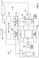
- FIG. 1 disclosed, generally, is an engine system 200 comprising a rotor shaft 210.
- the system 200 may be used to provide torque to change the speed of a primary shaft 215 of a gas turbine engine 217, illustrated schematically.
- the primary shaft 215 may be, for example, a fan shaft.
- the rotor shaft 210 and primary shaft 215 may be an integral shaft.
- the system 200 may include a plurality of components, including a first component 220 and a second component 230.
- the plurality of components may be operationally connected to the rotor shaft 210.
- the first component 220 may be a main machine (MM) as defined above in this document and the second component 230 may be a permanent magnet generator (PMG), sometimes referred to as a PMG assist motor.
- PMG assist motor sometimes referred to as a PMG assist motor.
- torque changing the speed of the primary shaft 215 of the gas turbine engine 217 may be obtained from a combination of the MM 220 providing primary driving torque and the PMG 230 providing supplemental torque.
- the PMG 230 provides such supplemental torque during engine startup.
- the PMG 230 with or without the MM 220, provides such supplemental torque to increase the engine speed during other flight legs, such as climb, cruise, loiter and landing.
- the system 200 may comprise a plurality of controllers including first controller 240 and a second controller 250.
- the plurality of controllers may control current to the plurality of components. That is, the first controller 240 may be an MM controller and the second controller 250 may be a PMG assist motor controller.
- the system 200 may further include a DC bus 260 operationally connected to the plurality of components, where the DC bus 260 is operationally connected to a primary engine controller 265.
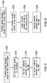
- a process S300 of providing speed changing torque to a gas turbine engine 217 is disclosed.
- the process may include step S320 the DC bus 260 providing power to the plurality of controllers.
- the first controller 240 may provide current to the MM 220 to provide primary torque to the gas turbine engine 217.
- the second controller 250 may provide current to the PMG 230 to provide supplemental torque to the gas turbine engine 217. From this, speed changing torque may be provide to the gas turbine engine 217.
- the plurality of components may include an exciter 270 and a rotating rectifier 280.
- FIG. 3 illustrates that process S300 may also include step S370 of the first controller 240 providing current to the exciter 270.
- the exciter 270 may provide excited current to the rotating rectifier 280.
- the rotating rectifier 280 may provide power to the MM 220 to magnetize the rotating field (i.e. the system forms an electromagnet). It is to be appreciated that in this configuration, where the PMG 230 provides supplemental power to the MM 220, the steps in FIG. 3 occur before the steps in FIG. 2 .
- the shaft 210 may be a fan shaft in a gas turbine engine.
- the PMG 230 may provide supplemental torque during an engine start-up mode, for example, when engine operational speeds are below a self-sustaining mode, when an engine is on-wing of an aircraft but the aircraft is not in flight.
- a start of a gas turbine engine 217 may be achieved without, for example, bleeding energy from a secondary system such as fuselage mounted auxiliary power unit (APU).
- the PMG 230 may be used, with or without the MM 220 depending on torque requirements, to provide torque to the gas turbine engine 217, to increase rotational speed, and thereby obtain additional thrust.
- the PMG 230 may rotationally drive the engine 217 during engine maintenance, that is, without the need for primary torque from the MM 220. In one embodiment the PMG 230 may rotationally drive the engine 217 for a time period at engine startup and/or shutdown to prevent bowing of the engine rotor shaft caused by rapid changes in engine temperatures at those transitional engine phases. It is to be appreciated that the plurality of components of the engine are commonly referred to as a generator 300 when used during normal operational speeds. During such conditions the MM 220 may generate power that may be used to power, for example, aircraft systems.
- the above disclosure provides a system and method of completing the engine start for the aircraft where required start torque may be greater than that provided by the MM alone.
- Such method may utilize a permanent magnet generator (PMG) 230 to provide additional torque during start mode.
- PMG permanent magnet generator
- a main machine controller 240 is illustrated that provides excitation through the exciter 270, which may receive excitation power from the alternating current (AC) aircraft bus 260.
- the exciter 270 may be a three phase induction exciter.
- Air framers may be integrating additional PMGs 230 into the generator 300 to power items such as flight controls and hydraulic pumps. These PMGs 230 may be utilized for start assist as well. Once the system is online, it may move back to a generate mode for operating the generator 300.
- the PMG Assist Motor Controller (250) can be utilized as a rectifier to source DC (direct current) power to the controller and exciter for generate mode.
- the PMG 230 may be operated without the MM 220 allowing for lower power operation without the need of operating the generator excitation system. This may allow for more efficient operation and minimizes thermal stress on the excitation system of an engine main generator.
- the disclosed embodiments may have the following benefits: (1) by splitting up the motor controllers, the motor controllers may be more effectively air cooled; (2) either controller may be used for other relatively smaller loads like fan applications or hydraulics, which may tend to be smaller loads on narrow body aircraft; (3) electric engine start may occur without oversizing a main generator beyond certain desired limits; (4) using the PMG 230 for motoring during low speed motoring for maintenance or bowed rotor shaft conditions may allow for reducing overall power required; (5) the PMG 230, in some embodiments, may be used as a position sensor; (6) the disclosed system may provide for an elimination of the bleed air system and duct work; and (7) the disclosed system may provide for an elimination of an air turbine starter.
- Electric engine start may be a feasible technology for architectures where the engine start power requirements may be lower than power generation requirements.
- the ratio of start power to power generation requirements may be in or near a range of three to five (3:5).
- the disclosed architecture may lend itself towards wide body commercial aircraft and military aircraft because the engine start requirements may be a fraction of required power during power generate mode. This may provide a weight reduction opportunity.
- the wide body market may be able to support the liquid cooled starter/motor controller because of an available space and an ability to multiplex a controller to support an engine start, as well as air management systems and hydraulic pumps.
- the disclosed configuration may allow for a common motor controller, resulting in a relatively smaller package.
- the military market may support liquid cooled systems because the cooling medium may be fuel, which may be heated prior to injection in the engine.
- the engine requirements may be such that the start power may be greater than, for example, engine requirements during the power generating mode.
- An example of this may be where start power of a commercial aircraft is 150 kW and the electrical system power requirements otherwise may be 90 kW. It is to be appreciated by one reading this disclosure that the start power may drive the size of a generator and force liquid cooled motor controllers.
Landscapes
- Engineering & Computer Science (AREA)
- Power Engineering (AREA)
- Chemical & Material Sciences (AREA)
- Combustion & Propulsion (AREA)
- Mechanical Engineering (AREA)
- General Engineering & Computer Science (AREA)
- Aviation & Aerospace Engineering (AREA)
- Control Of Eletrric Generators (AREA)
Applications Claiming Priority (1)
| Application Number | Priority Date | Filing Date | Title |
|---|---|---|---|
| US16/138,608 US10723469B2 (en) | 2018-09-21 | 2018-09-21 | System and method for driving electrically driving a gas turbine engine via a wound field synchronous machine assisted by a PMG |
Publications (2)
| Publication Number | Publication Date |
|---|---|
| EP3627689A1 true EP3627689A1 (de) | 2020-03-25 |
| EP3627689B1 EP3627689B1 (de) | 2022-03-02 |
Family
ID=68051728
Family Applications (1)
| Application Number | Title | Priority Date | Filing Date |
|---|---|---|---|
| EP19198994.6A Active EP3627689B1 (de) | 2018-09-21 | 2019-09-23 | System und verfahren zum elektrischen antreiben eines gasturbinenmotors über eine gewickelte feldsynchronmaschine mit pmg-unterstützung |
Country Status (2)
| Country | Link |
|---|---|
| US (1) | US10723469B2 (de) |
| EP (1) | EP3627689B1 (de) |
Cited By (2)
| Publication number | Priority date | Publication date | Assignee | Title |
|---|---|---|---|---|
| WO2024256769A1 (fr) * | 2023-06-16 | 2024-12-19 | Safran Electrical & Power | Generateur a excitation hybride d'un systeme de propulsion hybride electrique |
| EP4456411A3 (de) * | 2023-04-26 | 2025-01-29 | Hamilton Sundstrand Corporation | Motorstartsystem mit erreger |
Families Citing this family (3)
| Publication number | Priority date | Publication date | Assignee | Title |
|---|---|---|---|---|
| US11428171B2 (en) * | 2019-12-06 | 2022-08-30 | General Electric Company | Electric machine assistance for multi-spool turbomachine operation and control |
| US11936252B2 (en) * | 2021-07-08 | 2024-03-19 | Hamilton Sundstrand Corporation (HSC) | Exciter windings for wide speed operation |
| US12480449B2 (en) | 2022-08-22 | 2025-11-25 | General Electric Company | Propulsion system including an electric machine for starting a gas turbine engine |
Citations (3)
| Publication number | Priority date | Publication date | Assignee | Title |
|---|---|---|---|---|
| EP2001121A2 (de) * | 2007-06-05 | 2008-12-10 | Honeywell International Inc. | Motorstartsystem mit Quadraturwechselstromerregung |
| EP2911291A2 (de) * | 2014-02-24 | 2015-08-26 | The Boeing Company | Verfahren und System zur Steuerung einer synchronen Maschine als Generator/Anlasser |
| WO2016133502A1 (en) * | 2015-02-18 | 2016-08-25 | Ge Aviation Systems Llc | Aircraft starting and generating system |
Family Cites Families (27)
| Publication number | Priority date | Publication date | Assignee | Title |
|---|---|---|---|---|
| US4625160A (en) * | 1984-12-17 | 1986-11-25 | Sundstrand Corporation | Variable speed constant frequency generating system |
| US4772802A (en) * | 1987-08-19 | 1988-09-20 | Sundstrand Corporation | Starting/generating system |
| US4868406A (en) * | 1988-07-05 | 1989-09-19 | Sundstrand Corporation | Electrically compensated constant speed drive with prime mover start capability |
| US5023537A (en) * | 1989-08-23 | 1991-06-11 | Sundstrand Corporation | Low frequency feeder fault protection |
| US5561602A (en) * | 1994-07-01 | 1996-10-01 | General Electric Company | Tunnel operation for self-propelled traction vehicles |
| US5625276A (en) * | 1994-09-14 | 1997-04-29 | Coleman Powermate, Inc. | Controller for permanent magnet generator |
| CN1199680A (zh) | 1997-05-15 | 1998-11-25 | 时作江 | 一种节油汽车 |
| US5929537A (en) | 1997-06-30 | 1999-07-27 | Sundstrand Corporation | PMG main engine starter/generator system |
| US6631080B2 (en) | 2001-06-06 | 2003-10-07 | Hybrid Power Generation Systems Llc | Systems and methods for boosting DC link voltage in turbine generators |
| US6768278B2 (en) | 2002-08-06 | 2004-07-27 | Honeywell International, Inc. | Gas turbine engine starter generator with switchable exciter stator windings |
| US6906479B2 (en) | 2002-08-06 | 2005-06-14 | Honeywell International, Inc. | Gas turbine engine starter generator with multiple windings on each exciter stator pole |
| US20060087293A1 (en) * | 2004-10-26 | 2006-04-27 | Honeywell International, Inc. | AC generator with independently controlled field rotational speed |
| US7301311B2 (en) * | 2006-02-22 | 2007-11-27 | Honeywell International, Inc. | Brushless starter-generator with independently controllable exciter field |
| US7508086B2 (en) * | 2006-03-24 | 2009-03-24 | General Electric Company | Aircraft engine starter/generator and controller |
| US7687928B2 (en) * | 2006-06-14 | 2010-03-30 | Smiths Aerospace, Llc | Dual-structured aircraft engine starter/generator |
| US7863868B2 (en) * | 2007-06-05 | 2011-01-04 | Honeywell International Inc. | Generator with quadrature AC excitation |
| US7808215B2 (en) * | 2007-07-02 | 2010-10-05 | Hamilton Sundstrand Corporation | Active damping for synchronous generator torsional oscillations |
| US8148834B2 (en) | 2009-05-19 | 2012-04-03 | General Electric Company | Aircraft engine starting/generating system and method of control |
| US8362728B2 (en) * | 2010-09-15 | 2013-01-29 | Hamilton Sundstrand Corporation | Rotor position detection at standstill and low speeds using a PMG to operate a wound field synchronous machine |
| US8593095B2 (en) * | 2011-05-24 | 2013-11-26 | Hamilton Sundstrand Corporation | Wound field synchronous machine rotor tracking using a carrier injection sensorless signal and exciter current |
| US20130284529A1 (en) * | 2012-04-30 | 2013-10-31 | John Franklin Kral | Cooling system for mobile machine |
| US9441599B2 (en) | 2012-07-17 | 2016-09-13 | Altigreen Propulsion Labs Private Limited | Induction motor-permanent magnet generator tandem configuration starter-generator for hybrid vehicles |
| US9452814B2 (en) * | 2014-03-10 | 2016-09-27 | The Boeing Company | Autonomous power generation in submersible environments |
| US20150345370A1 (en) * | 2014-06-02 | 2015-12-03 | Progress Rail Services Corporation | Cooling control system for a mobile machine |
| CN107251407A (zh) | 2015-02-18 | 2017-10-13 | 通用电气航空系统有限责任公司 | 飞行器启动和发电系统 |
| US10326394B2 (en) * | 2017-10-24 | 2019-06-18 | Hamilton Sundstrand Corporation | Wound field generator overvoltage prevention |
| US10693405B2 (en) * | 2018-01-05 | 2020-06-23 | Hamilton Sundstrand Corporation | Permanent magnet generator with magnetic rotor band |
-
2018
- 2018-09-21 US US16/138,608 patent/US10723469B2/en active Active
-
2019
- 2019-09-23 EP EP19198994.6A patent/EP3627689B1/de active Active
Patent Citations (3)
| Publication number | Priority date | Publication date | Assignee | Title |
|---|---|---|---|---|
| EP2001121A2 (de) * | 2007-06-05 | 2008-12-10 | Honeywell International Inc. | Motorstartsystem mit Quadraturwechselstromerregung |
| EP2911291A2 (de) * | 2014-02-24 | 2015-08-26 | The Boeing Company | Verfahren und System zur Steuerung einer synchronen Maschine als Generator/Anlasser |
| WO2016133502A1 (en) * | 2015-02-18 | 2016-08-25 | Ge Aviation Systems Llc | Aircraft starting and generating system |
Cited By (3)
| Publication number | Priority date | Publication date | Assignee | Title |
|---|---|---|---|---|
| EP4456411A3 (de) * | 2023-04-26 | 2025-01-29 | Hamilton Sundstrand Corporation | Motorstartsystem mit erreger |
| WO2024256769A1 (fr) * | 2023-06-16 | 2024-12-19 | Safran Electrical & Power | Generateur a excitation hybride d'un systeme de propulsion hybride electrique |
| FR3149870A1 (fr) * | 2023-06-16 | 2024-12-20 | Safran Electrical & Power | Générateur à excitation hybride d’un système de propulsion hybride électrique |
Also Published As
| Publication number | Publication date |
|---|---|
| US20200094977A1 (en) | 2020-03-26 |
| US10723469B2 (en) | 2020-07-28 |
| EP3627689B1 (de) | 2022-03-02 |
Similar Documents
| Publication | Publication Date | Title |
|---|---|---|
| EP3627689B1 (de) | System und verfahren zum elektrischen antreiben eines gasturbinenmotors über eine gewickelte feldsynchronmaschine mit pmg-unterstützung | |
| EP2568122A2 (de) | Verfahren und Vorrichtung zur Stromerzeugung aus einem Gasturbinenmotor | |
| US9776583B2 (en) | Aircraft electrical system | |
| CN105339597B (zh) | 带有发电机的涡轮风扇发动机 | |
| EP3375981A1 (de) | Mit variabler geschwindigkeit ac-busgespeistes heckkegel-grenzflächenaufnahme-gegendruckelement | |
| JP6130689B2 (ja) | タービンエンジンの低圧スプールから入力動力を取り出すための装置 | |
| JP6001851B2 (ja) | 輸送機関に電力供給する方法およびシステム | |
| US11246237B2 (en) | Ram air fan and power electronics cooling systems | |
| EP3004565B1 (de) | Strahltriebwerksanordnung und verfahren zur erzeugung von elektrizität | |
| CN105765214B (zh) | 用于起动航空器的发动机的方法 | |
| EP2985901A1 (de) | Hybrides elektrisches impulsenergieantriebssystem für flugzeug | |
| CN108138738A (zh) | 用于起动飞行器发动机并操作飞行器的电源架构的方法和设备 | |
| US9573539B2 (en) | Electric system architecture for more-electric engine accessories | |
| US8823334B2 (en) | Method for starting an electric motor | |
| EP3228545A1 (de) | Hybrides elektrisches flugzeug mit system zur wärmerückgewinnung aus einem rankine-prozess | |
| US20140008972A1 (en) | Electrical power supply for an aircraft | |
| EP4401285A1 (de) | Elektrisches energiesystem mit verschiedenen axialen längen zur effizienten stromerzeugung | |
| US20120098329A1 (en) | Generator excitation during load fault conditions | |
| EP2611026A1 (de) | Generatorerregung während Ladefehlerbedingungen | |
| EP4456411A2 (de) | Motorstartsystem mit erreger | |
| EP3096448B1 (de) | Gewickelter generator mit elektrisch isolierter motorlichtmaschine | |
| EP4542847A1 (de) | Flugzeugmotorstart mit mehreren gemeinsamen motorsteuerungen |
Legal Events
| Date | Code | Title | Description |
|---|---|---|---|
| PUAI | Public reference made under article 153(3) epc to a published international application that has entered the european phase |
Free format text: ORIGINAL CODE: 0009012 |
|
| STAA | Information on the status of an ep patent application or granted ep patent |
Free format text: STATUS: THE APPLICATION HAS BEEN PUBLISHED |
|
| AK | Designated contracting states |
Kind code of ref document: A1 Designated state(s): AL AT BE BG CH CY CZ DE DK EE ES FI FR GB GR HR HU IE IS IT LI LT LU LV MC MK MT NL NO PL PT RO RS SE SI SK SM TR |
|
| AX | Request for extension of the european patent |
Extension state: BA ME |
|
| STAA | Information on the status of an ep patent application or granted ep patent |
Free format text: STATUS: REQUEST FOR EXAMINATION WAS MADE |
|
| 17P | Request for examination filed |
Effective date: 20200924 |
|
| RBV | Designated contracting states (corrected) |
Designated state(s): AL AT BE BG CH CY CZ DE DK EE ES FI FR GB GR HR HU IE IS IT LI LT LU LV MC MK MT NL NO PL PT RO RS SE SI SK SM TR |
|
| STAA | Information on the status of an ep patent application or granted ep patent |
Free format text: STATUS: EXAMINATION IS IN PROGRESS |
|
| 17Q | First examination report despatched |
Effective date: 20210118 |
|
| GRAP | Despatch of communication of intention to grant a patent |
Free format text: ORIGINAL CODE: EPIDOSNIGR1 |
|
| STAA | Information on the status of an ep patent application or granted ep patent |
Free format text: STATUS: GRANT OF PATENT IS INTENDED |
|
| RIC1 | Information provided on ipc code assigned before grant |
Ipc: F02C 7/268 20060101ALI20210909BHEP Ipc: F02C 6/00 20060101ALI20210909BHEP Ipc: F01D 15/10 20060101ALI20210909BHEP Ipc: F02N 11/04 20060101ALI20210909BHEP Ipc: H02P 1/46 20060101ALI20210909BHEP Ipc: H02P 6/20 20160101AFI20210909BHEP |
|
| INTG | Intention to grant announced |
Effective date: 20210924 |
|
| RIC1 | Information provided on ipc code assigned before grant |
Ipc: H02P 25/03 20160101ALI20210914BHEP Ipc: H02P 9/14 20060101ALI20210914BHEP Ipc: F02C 7/268 20060101ALI20210914BHEP Ipc: F02C 6/00 20060101ALI20210914BHEP Ipc: F01D 15/10 20060101ALI20210914BHEP Ipc: F02N 11/04 20060101ALI20210914BHEP Ipc: H02P 1/46 20060101ALI20210914BHEP Ipc: H02P 6/20 20160101AFI20210914BHEP |
|
| GRAS | Grant fee paid |
Free format text: ORIGINAL CODE: EPIDOSNIGR3 |
|
| GRAA | (expected) grant |
Free format text: ORIGINAL CODE: 0009210 |
|
| STAA | Information on the status of an ep patent application or granted ep patent |
Free format text: STATUS: THE PATENT HAS BEEN GRANTED |
|
| AK | Designated contracting states |
Kind code of ref document: B1 Designated state(s): AL AT BE BG CH CY CZ DE DK EE ES FI FR GB GR HR HU IE IS IT LI LT LU LV MC MK MT NL NO PL PT RO RS SE SI SK SM TR |
|
| REG | Reference to a national code |
Ref country code: GB Ref legal event code: FG4D |
|
| REG | Reference to a national code |
Ref country code: CH Ref legal event code: EP Ref country code: AT Ref legal event code: REF Ref document number: 1473083 Country of ref document: AT Kind code of ref document: T Effective date: 20220315 |
|
| REG | Reference to a national code |
Ref country code: DE Ref legal event code: R096 Ref document number: 602019012062 Country of ref document: DE |
|
| REG | Reference to a national code |
Ref country code: IE Ref legal event code: FG4D |
|
| REG | Reference to a national code |
Ref country code: LT Ref legal event code: MG9D |
|
| REG | Reference to a national code |
Ref country code: NL Ref legal event code: MP Effective date: 20220302 |
|
| PG25 | Lapsed in a contracting state [announced via postgrant information from national office to epo] |
Ref country code: SE Free format text: LAPSE BECAUSE OF FAILURE TO SUBMIT A TRANSLATION OF THE DESCRIPTION OR TO PAY THE FEE WITHIN THE PRESCRIBED TIME-LIMIT Effective date: 20220302 Ref country code: RS Free format text: LAPSE BECAUSE OF FAILURE TO SUBMIT A TRANSLATION OF THE DESCRIPTION OR TO PAY THE FEE WITHIN THE PRESCRIBED TIME-LIMIT Effective date: 20220302 Ref country code: NO Free format text: LAPSE BECAUSE OF FAILURE TO SUBMIT A TRANSLATION OF THE DESCRIPTION OR TO PAY THE FEE WITHIN THE PRESCRIBED TIME-LIMIT Effective date: 20220602 Ref country code: LT Free format text: LAPSE BECAUSE OF FAILURE TO SUBMIT A TRANSLATION OF THE DESCRIPTION OR TO PAY THE FEE WITHIN THE PRESCRIBED TIME-LIMIT Effective date: 20220302 Ref country code: HR Free format text: LAPSE BECAUSE OF FAILURE TO SUBMIT A TRANSLATION OF THE DESCRIPTION OR TO PAY THE FEE WITHIN THE PRESCRIBED TIME-LIMIT Effective date: 20220302 Ref country code: ES Free format text: LAPSE BECAUSE OF FAILURE TO SUBMIT A TRANSLATION OF THE DESCRIPTION OR TO PAY THE FEE WITHIN THE PRESCRIBED TIME-LIMIT Effective date: 20220302 Ref country code: BG Free format text: LAPSE BECAUSE OF FAILURE TO SUBMIT A TRANSLATION OF THE DESCRIPTION OR TO PAY THE FEE WITHIN THE PRESCRIBED TIME-LIMIT Effective date: 20220602 |
|
| REG | Reference to a national code |
Ref country code: AT Ref legal event code: MK05 Ref document number: 1473083 Country of ref document: AT Kind code of ref document: T Effective date: 20220302 |
|
| PG25 | Lapsed in a contracting state [announced via postgrant information from national office to epo] |
Ref country code: PL Free format text: LAPSE BECAUSE OF FAILURE TO SUBMIT A TRANSLATION OF THE DESCRIPTION OR TO PAY THE FEE WITHIN THE PRESCRIBED TIME-LIMIT Effective date: 20220302 Ref country code: LV Free format text: LAPSE BECAUSE OF FAILURE TO SUBMIT A TRANSLATION OF THE DESCRIPTION OR TO PAY THE FEE WITHIN THE PRESCRIBED TIME-LIMIT Effective date: 20220302 Ref country code: GR Free format text: LAPSE BECAUSE OF FAILURE TO SUBMIT A TRANSLATION OF THE DESCRIPTION OR TO PAY THE FEE WITHIN THE PRESCRIBED TIME-LIMIT Effective date: 20220603 Ref country code: FI Free format text: LAPSE BECAUSE OF FAILURE TO SUBMIT A TRANSLATION OF THE DESCRIPTION OR TO PAY THE FEE WITHIN THE PRESCRIBED TIME-LIMIT Effective date: 20220302 |
|
| PG25 | Lapsed in a contracting state [announced via postgrant information from national office to epo] |
Ref country code: NL Free format text: LAPSE BECAUSE OF FAILURE TO SUBMIT A TRANSLATION OF THE DESCRIPTION OR TO PAY THE FEE WITHIN THE PRESCRIBED TIME-LIMIT Effective date: 20220302 |
|
| PG25 | Lapsed in a contracting state [announced via postgrant information from national office to epo] |
Ref country code: SM Free format text: LAPSE BECAUSE OF FAILURE TO SUBMIT A TRANSLATION OF THE DESCRIPTION OR TO PAY THE FEE WITHIN THE PRESCRIBED TIME-LIMIT Effective date: 20220302 Ref country code: SK Free format text: LAPSE BECAUSE OF FAILURE TO SUBMIT A TRANSLATION OF THE DESCRIPTION OR TO PAY THE FEE WITHIN THE PRESCRIBED TIME-LIMIT Effective date: 20220302 Ref country code: RO Free format text: LAPSE BECAUSE OF FAILURE TO SUBMIT A TRANSLATION OF THE DESCRIPTION OR TO PAY THE FEE WITHIN THE PRESCRIBED TIME-LIMIT Effective date: 20220302 Ref country code: PT Free format text: LAPSE BECAUSE OF FAILURE TO SUBMIT A TRANSLATION OF THE DESCRIPTION OR TO PAY THE FEE WITHIN THE PRESCRIBED TIME-LIMIT Effective date: 20220704 Ref country code: EE Free format text: LAPSE BECAUSE OF FAILURE TO SUBMIT A TRANSLATION OF THE DESCRIPTION OR TO PAY THE FEE WITHIN THE PRESCRIBED TIME-LIMIT Effective date: 20220302 Ref country code: CZ Free format text: LAPSE BECAUSE OF FAILURE TO SUBMIT A TRANSLATION OF THE DESCRIPTION OR TO PAY THE FEE WITHIN THE PRESCRIBED TIME-LIMIT Effective date: 20220302 Ref country code: AT Free format text: LAPSE BECAUSE OF FAILURE TO SUBMIT A TRANSLATION OF THE DESCRIPTION OR TO PAY THE FEE WITHIN THE PRESCRIBED TIME-LIMIT Effective date: 20220302 |
|
| PG25 | Lapsed in a contracting state [announced via postgrant information from national office to epo] |
Ref country code: IS Free format text: LAPSE BECAUSE OF FAILURE TO SUBMIT A TRANSLATION OF THE DESCRIPTION OR TO PAY THE FEE WITHIN THE PRESCRIBED TIME-LIMIT Effective date: 20220702 Ref country code: AL Free format text: LAPSE BECAUSE OF FAILURE TO SUBMIT A TRANSLATION OF THE DESCRIPTION OR TO PAY THE FEE WITHIN THE PRESCRIBED TIME-LIMIT Effective date: 20220302 |
|
| REG | Reference to a national code |
Ref country code: DE Ref legal event code: R097 Ref document number: 602019012062 Country of ref document: DE |
|
| PLBE | No opposition filed within time limit |
Free format text: ORIGINAL CODE: 0009261 |
|
| STAA | Information on the status of an ep patent application or granted ep patent |
Free format text: STATUS: NO OPPOSITION FILED WITHIN TIME LIMIT |
|
| PG25 | Lapsed in a contracting state [announced via postgrant information from national office to epo] |
Ref country code: DK Free format text: LAPSE BECAUSE OF FAILURE TO SUBMIT A TRANSLATION OF THE DESCRIPTION OR TO PAY THE FEE WITHIN THE PRESCRIBED TIME-LIMIT Effective date: 20220302 |
|
| 26N | No opposition filed |
Effective date: 20221205 |
|
| PG25 | Lapsed in a contracting state [announced via postgrant information from national office to epo] |
Ref country code: SI Free format text: LAPSE BECAUSE OF FAILURE TO SUBMIT A TRANSLATION OF THE DESCRIPTION OR TO PAY THE FEE WITHIN THE PRESCRIBED TIME-LIMIT Effective date: 20220302 |
|
| PG25 | Lapsed in a contracting state [announced via postgrant information from national office to epo] |
Ref country code: MC Free format text: LAPSE BECAUSE OF FAILURE TO SUBMIT A TRANSLATION OF THE DESCRIPTION OR TO PAY THE FEE WITHIN THE PRESCRIBED TIME-LIMIT Effective date: 20220302 |
|
| REG | Reference to a national code |
Ref country code: CH Ref legal event code: PL |
|
| REG | Reference to a national code |
Ref country code: BE Ref legal event code: MM Effective date: 20220930 |
|
| PG25 | Lapsed in a contracting state [announced via postgrant information from national office to epo] |
Ref country code: LU Free format text: LAPSE BECAUSE OF NON-PAYMENT OF DUE FEES Effective date: 20220923 |
|
| P01 | Opt-out of the competence of the unified patent court (upc) registered |
Effective date: 20230603 |
|
| PG25 | Lapsed in a contracting state [announced via postgrant information from national office to epo] |
Ref country code: LI Free format text: LAPSE BECAUSE OF NON-PAYMENT OF DUE FEES Effective date: 20220930 Ref country code: IT Free format text: LAPSE BECAUSE OF FAILURE TO SUBMIT A TRANSLATION OF THE DESCRIPTION OR TO PAY THE FEE WITHIN THE PRESCRIBED TIME-LIMIT Effective date: 20220302 Ref country code: IE Free format text: LAPSE BECAUSE OF NON-PAYMENT OF DUE FEES Effective date: 20220923 Ref country code: CH Free format text: LAPSE BECAUSE OF NON-PAYMENT OF DUE FEES Effective date: 20220930 |
|
| PG25 | Lapsed in a contracting state [announced via postgrant information from national office to epo] |
Ref country code: BE Free format text: LAPSE BECAUSE OF NON-PAYMENT OF DUE FEES Effective date: 20220930 |
|
| PG25 | Lapsed in a contracting state [announced via postgrant information from national office to epo] |
Ref country code: HU Free format text: LAPSE BECAUSE OF FAILURE TO SUBMIT A TRANSLATION OF THE DESCRIPTION OR TO PAY THE FEE WITHIN THE PRESCRIBED TIME-LIMIT; INVALID AB INITIO Effective date: 20190923 |
|
| PG25 | Lapsed in a contracting state [announced via postgrant information from national office to epo] |
Ref country code: CY Free format text: LAPSE BECAUSE OF FAILURE TO SUBMIT A TRANSLATION OF THE DESCRIPTION OR TO PAY THE FEE WITHIN THE PRESCRIBED TIME-LIMIT Effective date: 20220302 |
|
| PG25 | Lapsed in a contracting state [announced via postgrant information from national office to epo] |
Ref country code: MK Free format text: LAPSE BECAUSE OF FAILURE TO SUBMIT A TRANSLATION OF THE DESCRIPTION OR TO PAY THE FEE WITHIN THE PRESCRIBED TIME-LIMIT Effective date: 20220302 |
|
| PG25 | Lapsed in a contracting state [announced via postgrant information from national office to epo] |
Ref country code: TR Free format text: LAPSE BECAUSE OF FAILURE TO SUBMIT A TRANSLATION OF THE DESCRIPTION OR TO PAY THE FEE WITHIN THE PRESCRIBED TIME-LIMIT Effective date: 20220302 |
|
| PG25 | Lapsed in a contracting state [announced via postgrant information from national office to epo] |
Ref country code: MT Free format text: LAPSE BECAUSE OF FAILURE TO SUBMIT A TRANSLATION OF THE DESCRIPTION OR TO PAY THE FEE WITHIN THE PRESCRIBED TIME-LIMIT Effective date: 20220302 |
|
| PGFP | Annual fee paid to national office [announced via postgrant information from national office to epo] |
Ref country code: DE Payment date: 20250820 Year of fee payment: 7 |
|
| PGFP | Annual fee paid to national office [announced via postgrant information from national office to epo] |
Ref country code: GB Payment date: 20250820 Year of fee payment: 7 |
|
| PGFP | Annual fee paid to national office [announced via postgrant information from national office to epo] |
Ref country code: FR Payment date: 20250820 Year of fee payment: 7 |