EP3627903A1 - Procédé d'émission de signaux et dispositif terminal - Google Patents
Procédé d'émission de signaux et dispositif terminal Download PDFInfo
- Publication number
- EP3627903A1 EP3627903A1 EP17921769.0A EP17921769A EP3627903A1 EP 3627903 A1 EP3627903 A1 EP 3627903A1 EP 17921769 A EP17921769 A EP 17921769A EP 3627903 A1 EP3627903 A1 EP 3627903A1
- Authority
- EP
- European Patent Office
- Prior art keywords
- uplink signals
- transmission power
- terminal device
- uplink
- effective transmission
- Prior art date
- Legal status (The legal status is an assumption and is not a legal conclusion. Google has not performed a legal analysis and makes no representation as to the accuracy of the status listed.)
- Withdrawn
Links
Images
Classifications
-
- H—ELECTRICITY
- H04—ELECTRIC COMMUNICATION TECHNIQUE
- H04B—TRANSMISSION
- H04B7/00—Radio transmission systems, i.e. using radiation field
- H04B7/005—Control of transmission; Equalising
-
- H—ELECTRICITY
- H04—ELECTRIC COMMUNICATION TECHNIQUE
- H04W—WIRELESS COMMUNICATION NETWORKS
- H04W52/00—Power management, e.g. Transmission Power Control [TPC] or power classes
- H04W52/04—Transmission power control [TPC]
- H04W52/30—Transmission power control [TPC] using constraints in the total amount of available transmission power
-
- H—ELECTRICITY
- H04—ELECTRIC COMMUNICATION TECHNIQUE
- H04W—WIRELESS COMMUNICATION NETWORKS
- H04W52/00—Power management, e.g. Transmission Power Control [TPC] or power classes
- H04W52/04—Transmission power control [TPC]
- H04W52/06—TPC algorithms
- H04W52/14—Separate analysis of uplink or downlink
- H04W52/146—Uplink power control
-
- H—ELECTRICITY
- H04—ELECTRIC COMMUNICATION TECHNIQUE
- H04W—WIRELESS COMMUNICATION NETWORKS
- H04W24/00—Supervisory, monitoring or testing arrangements
-
- H—ELECTRICITY
- H04—ELECTRIC COMMUNICATION TECHNIQUE
- H04W—WIRELESS COMMUNICATION NETWORKS
- H04W52/00—Power management, e.g. Transmission Power Control [TPC] or power classes
-
- H—ELECTRICITY
- H04—ELECTRIC COMMUNICATION TECHNIQUE
- H04W—WIRELESS COMMUNICATION NETWORKS
- H04W52/00—Power management, e.g. Transmission Power Control [TPC] or power classes
- H04W52/04—Transmission power control [TPC]
- H04W52/30—Transmission power control [TPC] using constraints in the total amount of available transmission power
- H04W52/36—Transmission power control [TPC] using constraints in the total amount of available transmission power with a discrete range or set of values, e.g. step size, ramping or offsets
- H04W52/367—Power values between minimum and maximum limits, e.g. dynamic range
-
- H—ELECTRICITY
- H04—ELECTRIC COMMUNICATION TECHNIQUE
- H04W—WIRELESS COMMUNICATION NETWORKS
- H04W72/00—Local resource management
- H04W72/04—Wireless resource allocation
-
- H—ELECTRICITY
- H04—ELECTRIC COMMUNICATION TECHNIQUE
- H04W—WIRELESS COMMUNICATION NETWORKS
- H04W72/00—Local resource management
- H04W72/04—Wireless resource allocation
- H04W72/044—Wireless resource allocation based on the type of the allocated resource
- H04W72/0473—Wireless resource allocation based on the type of the allocated resource the resource being transmission power
-
- H—ELECTRICITY
- H04—ELECTRIC COMMUNICATION TECHNIQUE
- H04W—WIRELESS COMMUNICATION NETWORKS
- H04W52/00—Power management, e.g. Transmission Power Control [TPC] or power classes
- H04W52/04—Transmission power control [TPC]
- H04W52/06—TPC algorithms
- H04W52/10—Open loop power control
-
- H—ELECTRICITY
- H04—ELECTRIC COMMUNICATION TECHNIQUE
- H04W—WIRELESS COMMUNICATION NETWORKS
- H04W52/00—Power management, e.g. Transmission Power Control [TPC] or power classes
- H04W52/04—Transmission power control [TPC]
- H04W52/06—TPC algorithms
- H04W52/16—Deriving transmission power values from another channel
-
- H—ELECTRICITY
- H04—ELECTRIC COMMUNICATION TECHNIQUE
- H04W—WIRELESS COMMUNICATION NETWORKS
- H04W52/00—Power management, e.g. Transmission Power Control [TPC] or power classes
- H04W52/04—Transmission power control [TPC]
- H04W52/18—TPC being performed according to specific parameters
- H04W52/28—TPC being performed according to specific parameters using user profile, e.g. mobile speed, priority or network state, e.g. standby, idle or non-transmission
- H04W52/281—TPC being performed according to specific parameters using user profile, e.g. mobile speed, priority or network state, e.g. standby, idle or non-transmission taking into account user or data type priority
-
- H—ELECTRICITY
- H04—ELECTRIC COMMUNICATION TECHNIQUE
- H04W—WIRELESS COMMUNICATION NETWORKS
- H04W72/00—Local resource management
- H04W72/12—Wireless traffic scheduling
- H04W72/1263—Mapping of traffic onto schedule, e.g. scheduled allocation or multiplexing of flows
- H04W72/1268—Mapping of traffic onto schedule, e.g. scheduled allocation or multiplexing of flows of uplink data flows
-
- H—ELECTRICITY
- H04—ELECTRIC COMMUNICATION TECHNIQUE
- H04W—WIRELESS COMMUNICATION NETWORKS
- H04W72/00—Local resource management
- H04W72/50—Allocation or scheduling criteria for wireless resources
- H04W72/56—Allocation or scheduling criteria for wireless resources based on priority criteria
- H04W72/566—Allocation or scheduling criteria for wireless resources based on priority criteria of the information or information source or recipient
- H04W72/569—Allocation or scheduling criteria for wireless resources based on priority criteria of the information or information source or recipient of the traffic information
Definitions
- Embodiments of the present disclosure relate to the field of communication, and more particularly, to a signal transmission method and a terminal device.
- an antenna array of a terminal device may include a plurality of antenna panels, which may be used for transmitting uplink signals at the same time.
- one antenna panel may include multiple antenna units, and different antenna panels may use different Radio Frequency (RF) channels.
- RF Radio Frequency
- the embodiments of the disclosure provides a signal transmission method and a terminal device.
- the terminal device can still simultaneously transmit multiple uplink signal within a same frequency domain set.
- a signal transmission method including: determining, by the terminal device, an effective transmission power of a plurality of uplink signals; and transmitting, by the terminal device, the plurality of uplink signals simultaneously in a same frequency domain resource set according to the effective transmission power of the plurality of uplink signals.
- the terminal device determines, according to a certain manner of power distribution, the effective transmission power respectively for the plurality of uplink signals to be transmitted simultaneously in the same frequency domain resource set and, thus, transmit the plurality of uplink signals simultaneously in the same frequency domain resource set according to the effective transmission power of the plurality of uplink signals.
- the terminal device may be still able to re-determine, according to the manner of power distribution described in embodiments of the disclosure, the effective transmission power respectively for the plurality of uplink signals to be transmitted and, thus, transmit the plurality of uplink signals simultaneously in the same frequency domain resource.
- the plurality of uplink signals include uplink data or an uplink reference signal.
- the plurality of uplink signals are uplink signals scheduled by same downlink control information (DCI), or uplink signals respectively scheduled by different DCIs.
- DCI downlink control information
- the same frequency domain resource set includes: a same carrier, a same bandwidth part, a same sub-band, or a same set of physical resource block (PRB).
- PRB physical resource block
- the determining, by the terminal device, an effective transmission power of a plurality of uplink signals includes: determining, by the terminal device, the effective transmission power of the plurality of uplink signals according to a number of the plurality of uplink signals.
- the determining, by the terminal device, the effective transmission power of the plurality of uplink signals according to a number of the plurality of uplink signals includes: determining, by the terminal device, a maximum supported transmission power of each uplink signal among the plurality of uplink signals according to the number of the plurality of uplink signals; and determining, by the terminal device, the effective transmission power of the each uplink signal based on the maximum supported transmission power of the each uplink signal.
- the terminal device may determine, according to the maximum transmission power supported by the terminal device P max and the number of the plurality of uplink signals N, the maximum supported transmission power of each uplink signal is P max /N. Then, the terminal device may determine, through a conventional procedure of uplink power control, the effective transmission power of the each uplink signal based on the maximum supported transmission power of the each uplink signal.
- the determining, by the terminal device, the effective transmission power of the plurality of uplink signals according to a number of the plurality of uplink signals includes: determining, by the terminal device, an expected transmission power of the each uplink signal among the plurality of uplink signals being reduced based on a ratio corresponding to the number of the plurality of uplink signals, as the effective transmission power of the each uplink signal.
- the expected transmission power of the each uplink signal among the plurality of uplink signals is P i , where 0 ⁇ i ⁇ N, N is the number of the plurality of uplink signals, and each value of N corresponds to a ratio. If the number N corresponds to a ratio of 1/N, the expected transmission power of the each uplink signal may be reduced to P i /N.
- the procedure for reducing the expected transmission power may be performed, for example, when a power consumption of the terminal device needs to be reduced, or only when a sum of the expected transmission powers of the plurality of uplink signals exceeds the maximum transmission power supported by the terminal device.
- the determining, by the terminal device, an effective transmission power of a plurality of uplink signals includes: determining, by the terminal device, the effective transmission power of the plurality of uplink signals according to priority information of the plurality of uplink signals.
- the method before the determining, by the terminal device, the effective transmission power of the plurality of uplink signals according to priority information of the plurality of uplink signals, the method further includes: determining, by the terminal device, the priority information of the plurality of uplink signals according to at least one of following information: a signal type of the plurality of uplink signals, a control signaling used for scheduling the plurality of uplink signals, a type of information carried by the plurality of uplink signals, and an order by which the plurality of uplink signals are scheduled.
- the determining, by the terminal device, the priority information of the plurality of uplink signals according to the control signaling used for scheduling the plurality of uplink signals includes: receiving, by the terminal device, a plurality of DCIs used for scheduling the plurality of uplink signals, the plurality of DCIs carrying the priority information of the plurality of uplink signals; or receiving, by the terminal device, the plurality of DCIs, and determining the priority information of the plurality of uplink signals according to information of modulation coding scheme (MCS) carried in the plurality of DCIs.
- MCS modulation coding scheme
- the determining, by the terminal device, the effective transmission power of the plurality of uplink signals according to priority information of the plurality of uplink signals includes: allocating, by the terminal device, respective minimum transmission powers for the plurality of uplink signals; and allocating, by the terminal device according to the priority information of the plurality of uplink signals, remaining transmission power in a maximum supportable transmission power excluding the minimum transmission powers of the plurality of uplink signals to at least part of the plurality of uplink signals.
- the terminal device allocates respective minimum transmission powers P min for each uplink signal. Then, the terminal device allocates the remaining transmission power P r according to a priority oerder of the uplink signals.
- the terminal device may acquire the priority information of those three signals by forgoing process, assuming the priority from high to low is signal 1 > signal 2 > signal 3, then the terminal device allocates remaining transmission power P r firstly to signal 1 with the highest priority, for example, causing the transmission P min thereof to reach its maximum transmission power Pi-max; if there is still surplus of the remaining transmission power P r , then the terminal device proceeds with allocation of transmission power for signal 2; if there is still surplus of the remaining transmission power P r , after the transmission power P min of signal 2 reaches its maximum transmission power P 2-max , then the terminal device proceeds with allocation of transmission power for signal 3. When the remaining transmission power is consumed out during the process of allocation and not enough for continuous allocation, the operation may be stopped.
- the effective transmission power of the signal which is the last one to be allocated with
- the priority information of the plurality of uplink signals is configured by a network device in advance for the plurality of uplink signals.
- the determining, by the terminal device, an effective transmission power of a plurality of uplink signals includes: determining by the terminal device, if a sum of expected transmission powers of the plurality of uplink signals exceeds a maximum transmission power supported by the terminal device, the expected transmission power of each uplink signal among the plurality of uplink signals being reduced based on a ratio of the maximum transmission power to the sum of expected transmission powers of the plurality of uplink signals, as the effective transmission power of the each uplink signal.
- the terminal device may reduce the effective transmission power of the i-th uplink signal to Pi ⁇ (P max /P a ).
- the determining, by the terminal device, an effective transmission power of a plurality of uplink signals includes: receiving, by the terminal device, indication information sent by a network device, the indication information indicating a power control parameter corresponding to the plurality of uplink signals; and determining, by the terminal device, the effective transmission power of the plurality of uplink signals according to the power control parameter corresponding to the plurality of uplink signals.
- the transmitting, by the terminal device, the plurality of uplink signals simultaneously in a same frequency domain resource set according to the effective transmission power of the plurality of uplink signals includes: transmitting, by the terminal device, the plurality of uplink signals simultaneously on different frequency domain resource in the same frequency domain resource set according to the effective transmission power of the plurality of uplink signals.
- the transmitting, by the terminal device, the plurality of uplink signals simultaneously in a same frequency domain resource set according to the effective transmission power of the plurality of uplink signals includes: transmitting, by the terminal device, the plurality of uplink signals simultaneously in the same frequency domain resource set through different antenna panels according to the effective transmission power of the plurality of uplink signals.
- the transmitting, by the terminal device, the plurality of uplink signals simultaneously in a same frequency domain resource set according to the effective transmission power of the plurality of uplink signals includes: transmitting, by the terminal device, the plurality of uplink signals simultaneously in the same frequency domain resource set through different beams according to the effective transmission power of the plurality of uplink signals.
- a terminal device configured to perform the operations of terminal device as described in the first aspect or any possible implementation thereof.
- the terminal device may include any module units configured to perform the operations of terminal device as described in the first aspect or any possible implementation thereof.
- a terminal device including a processor, a transceiver and a memory.
- the processor, the transceiver, and the memory communicate with each other through an internal connection path.
- the memory is configured to store instructions
- the processor is configured to execute instructions stored by the memory.
- the execution causes the terminal device to perform the method as described in the first aspect or any possible implementation thereof, or causes the terminal device to be implemented as the terminal device provided by the third aspect.
- a computer-readable storage medium configured to store a program, the program causes the terminal device to perform the signal transmission method as described in the first aspect or any possible implementation thereof.
- a system chip including: an input interface, an output interface, a processor, and a memory.
- the processor is configured to execute instructions stored in the memory. When the instructions are executed, the processor is able to implement the method as described in the first aspect or any possible implementation thereof.
- a computer program product including instructions which, when run on a computer, causes the computer to perform the method as described in the first aspect or any possible implementation thereof.
- GSM Global System of Mobile communication
- CDMA Code Division Multiple Access
- WCDMA Wideband Code Division Multiple Access
- LTE Long Term Evolution
- FDD Frequency Division Duplex
- TDD Time Division Duplex
- UMTS Universal Mobile Telecommunication System
- the embodiments of the present disclosure are described with reference to a terminal device.
- the terminal device may also be referred to as user equipment (UE), an access terminal, a subscriber unit, a subscriber station, a mobile station, a remote station, a remote terminal, a mobile device, a user terminal, a terminal, a wireless communication device, a user agent, or a user apparatus.
- UE user equipment
- an access terminal a subscriber unit, a subscriber station, a mobile station, a remote station, a remote terminal, a mobile device, a user terminal, a terminal, a wireless communication device, a user agent, or a user apparatus.
- the access terminal may be a cellular phone, a cordless phone, a Session Initiation Protocol (SIP) phone, a Wireless Local Loop (WLL) station, a Personal Digital Assistant (PDA), a handheld device having a wireless communication function, a computing device, or another processing device connected to a wireless modem, a vehicle-mounted device, a wearable device, a terminal device in future 5G network, a terminal device in future evolved Public Land Mobile Network (PLMN) network and the like.
- SIP Session Initiation Protocol
- WLL Wireless Local Loop
- PDA Personal Digital Assistant
- the network device may be a device used for communicating with the terminal device, for example, may be a Base Transceiver Station (BTS) in the GSM system or CDMA, or may be a NodeB (NB) in the WCDMA system, or may be an Evolutional Node B (eNB or eNodeB) in the LTE system.
- BTS Base Transceiver Station
- NB NodeB
- eNB Evolutional Node B
- the network device may be a relay station, an access point, an in-vehicle device, a wearable device, a network side device in the future 5G network, network side device in the future evolved PLMN network, and the like.
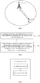
- Fig. 1 is a schematic structural diagram illustrating an application scenario according to an embodiment of the disclosure.
- the communication system in Fig. 1 may include a network device 10 and a terminal device 20.
- the network device 10 is configured to provide communication services for the terminal device 20 and access the core network.
- the terminal device 20 may access the network by searching for synchronization signals, broadcast signals, and the like transmitted by the network device 10, thereby performing communication with the network.
- the arrows shown in Fig. 1 may represent uplink/downlink transmissions performed via a cellular link between the terminal device 20 and the network device 10.
- the network in the embodiment of the disclosure may refer to a Public Land Mobile Network (PLMN), a Device to Device (D2D) network, a Machine to Machine/Man (M2M) network, or the like
- PLMN Public Land Mobile Network
- D2D Device to Device
- M2M Machine to Machine/Man
- Fig. 1 is only a simplified schematic diagram of an example, and other terminal devices may also be included in the network, which are not shown in Fig. 1 .
- Fig. 2 is a flow chart illustrating a signal transmission method according to an embodiment of the disclosure.
- the method illustrated in Fig. 2 may be performed by a terminal device, for example, the terminal device 20 as shown in Fig. 1 .
- the signal transmission method includes following steps.
- step 210 the terminal device determines an effective transmission power of a plurality of uplink signals.
- step 220 the terminal device transmits the plurality of uplink signals simultaneously in a same frequency domain resource set according to the effective transmission power of the plurality of uplink signals.
- the terminal device determines respective effective transmission powers for the plurality of uplink signals, so that, through reasonable distribution of transmission power, the terminal device can transmit the plurality of uplink signals simultaneously in the same frequency domain resource set according to the effective transmission power of the plurality of uplink signals.
- the uplink signal When the terminal device sends only one uplink signal, the uplink signal may be subjected to, for example, open-loop power control or closed-loop power control by using related parameters, and a transmission power can be determined for the uplink information, such transmission power may be referred to as the expected transmission power in embodiments of the disclosure.
- the expected transmission power of an uplink signal may be determined by existing means.
- the plurality of uplink signals are to be simultaneously transmitted. Therefore, when the terminal device is scheduled to transmit the plurality of uplink signals simultaneously in the same frequency domain resource set, if those uplink signals are still transmitted simultaneously according to the expected transmission power of each uplink signal, the transmission power of the terminal device may be limited.
- embodiments of the disclosure provide following manners to re-determine the effective transmission power of each uplink signal for the each uplink signal, so that the terminal device can transmit the plurality of uplink signals simultaneously in the same frequency domain resource set according to the effective transmission power of the plurality of uplink signals.
- the plurality of uplink signals include uplink data or an uplink reference signal.
- the plurality of uplink signals may be a plurality of Physical Uplink Shared Channels (PUSCHs), or may be different transport layers within one PUSCH, or may be different codewords within one PUSCH.
- the plurality of uplink signals may be a plurality of Sounding Reference Signals (SRSs).
- the plurality of uplink signals are uplink signals scheduled by same downlink control information (DCI), or uplink signals respectively scheduled by different DCIs.
- DCI downlink control information
- the uplink signals may be a plurality of PUSCHs scheduled by the same DCI, or a plurality of aperiodic SRSs triggered by the same DCI, or a plurality of independent PUSCHs respectively scheduled by a plurality of DCIs, or a plurality of independent aperiodic SRSs respectively triggered by a plurality of DCIs.
- the same frequency domain resource set includes: a same carrier, a same bandwidth part, a same sub-band, or a same set of physical resource block (PRB).
- PRB physical resource block
- the frequency domain resource set may be one carrier, one bandwidth part, one sub-band, or one PRB set.
- the terminal device determines the effective transmission power of a plurality of uplink signals includes: determining, by the terminal device, the effective transmission power of the plurality of uplink signals according to a number of the plurality of uplink signals.
- the terminal device may specifically determine the effective transmission power of the plurality of uplink signals according to the number of the plurality of uplink signals in the following two manners.
- the terminal device directly determines a maximum supported transmission power for each of the plurality of uplink signals according to the number of the plurality of uplink signals, and determines the effective manners power for each uplink signal based on the maximum supported transmission power.
- the terminal device obtains a ratio according to the number of the plurality of uplink signals, and reduces the expected transmission power of each uplink signal according to the ratio, thereby obtaining the effective transmission power of each uplink signal. Details will be described below.
- the determining, by the terminal device, the effective transmission power of the plurality of uplink signals according to a number of the plurality of uplink signals includes: determining, by the terminal device, a maximum supported transmission power of each uplink signal among the plurality of uplink signals according to the number of the plurality of uplink signals; and determining, by the terminal device, the effective transmission power of the each uplink signal based on the maximum supported transmission power of the each uplink signal.
- the terminal device may determine, according to the maximum transmission power supported by the terminal device P max and the number of the plurality of uplink signals N, the maximum supported transmission power of each uplink signal is P max /N. Then, the terminal device may determine, through a conventional procedure of uplink power control, the effective transmission power of the each uplink signal based on the maximum supported transmission power of the each uplink signal.
- Each uplink signal has its own maximum supported transmission power, and the effective transmission power used for transmitting the uplink signal does not exceed the maximum supported transmission power corresponding to the uplink signal.
- the maximum transmission power supported by the terminal device is a whole transmission power that the terminal device can provide for one transmission.
- the determining, by the terminal device, the effective transmission power of the plurality of uplink signals according to a number of the plurality of uplink signals includes: determining, by the terminal device, an expected transmission power of the each uplink signal among the plurality of uplink signals being reduced based on a ratio corresponding to the number of the plurality of uplink signals, as the effective transmission power of the each uplink signal.
- the expected transmission power of the each uplink signal among the plurality of uplink signals is P i , where 0 ⁇ i ⁇ N, N is the number of the plurality of uplink signals, and each value of N corresponds to a ratio. If the number N corresponds to a ratio of 1/N, the expected transmission power of the each uplink signal may be reduced to P i /N. If the number N corresponds to a ratio of 1/2N, the expected transmission power of the each uplink signal may be reduced to P i /2N.
- the procedure for reducing the expected transmission power may be performed, for example, when a power consumption of the terminal device needs to be reduced, or only when a sum of the expected transmission powers of the plurality of uplink signals exceeds the maximum transmission power supported by the terminal device.
- the terminal device determines the effective transmission power of a plurality of uplink signals includes: determining, by the terminal device, the effective transmission power of the plurality of uplink signals according to priority information of the plurality of uplink signals.
- the priority information of the plurality of uplink signals may be, for example, configured by a network device in advance for the plurality of uplink signals.
- the method may further include: determining, by the terminal device, the priority information of the plurality of uplink signals according to at least one of following information: a signal type of the plurality of uplink signals, a control signaling used for scheduling the plurality of uplink signals, a type of information carried by the plurality of uplink signals, and an order by which the plurality of uplink signals are scheduled.
- the terminal device may acquire the priority information of multiple uplink information by receiving a plurality of DCIs used for scheduling the plurality of uplink signals, where the plurality of DCIs carry the priority information of the plurality of uplink signals.
- the terminal device may receive the plurality of DCIs used for scheduling the plurality of uplink signals, and determine the priority information of the plurality of uplink signals according to information of Modulation Coding Mode (MCS) carried in the plurality of DCIs.
- MCS Modulation Coding Mode
- the network device may independently indicate an MCS level of each uplink signal for the plurality of uplink signals through one or more DCIs, the higher the MCS level of the uplink signal, the higher the priority thereof.
- the terminal device may determine the priority information of the plurality of uplink signals according to the type of information carried by the plurality of uplink signals based on the following rules.
- a physical uplink control channel (PUCCH) has a higher priority than any of PUSCH, SRS, and Phase Tracking Reference Signal (PTRS), PTRS has a higher priority than SRS, PUSCH has a higher priority than SRS, and PUCCH carrying information of Acknowledgement (ACK) / Negative Acknowledgement (NACK) has a higher priority than PUCCH carrying Channel State Information (CSI).
- PUCCH physical uplink control channel
- PTRS Phase Tracking Reference Signal
- PUSCH has a higher priority than SRS
- PUCCH carrying information of Acknowledgement (ACK) / Negative Acknowledgement (NACK) has a higher priority than PUCCH carrying Channel State Information (CSI).
- ACK Acknowledgement
- NACK Negative Acknowledgement
- PUSCH carrying Uplink Control Information has a higher priority than PUSCH without carrying UCI.
- PUSCH carrying Ultra Reliable Low Latency Communication (URLLC) data has a higher priority than PUSCH carrying Enhanced Mobile Broadband (eMBB) data.
- URLLC Ultra Reliable Low Latency Communication
- the terminal device determines the priority information of the plurality of uplink signals according to the order by which the plurality of uplink signals are scheduled, if the plurality of uplink signals are respectively scheduled by a plurality of DCIs, the uplink signal scheduled by a DCI firstly received by the terminal device has a higher priority than that scheduled by a DCI subsequently received by the terminal device.
- the uplink signal scheduled by a DCI subsequently received by the terminal device has a higher priority than that scheduled by a DCI firstly received by the terminal device.
- the terminal device may determine the effective transmission power of the plurality of uplink signals according to the priority information of the plurality of uplink signals through following ways.
- the determining, by the terminal device, the effective transmission power of the plurality of uplink signals according to priority information of the plurality of uplink signals includes: allocating, by the terminal device, respective minimum transmission powers for the plurality of uplink signals; and allocating, by the terminal device according to the priority information of the plurality of uplink signals, remaining transmission power in a maximum supportable transmission power excluding the minimum transmission powers of the plurality of uplink signals to at least part of the plurality of uplink signals.
- the terminal device may temporarily allocate the respective minimum transmission power (also may be referred to as minimum supported transmission power) for the plurality of uplink signals. Then, the terminal device subtracts the minimum supported transmission power of the plurality of uplink signals from the maximum supported transmission power, and allocates the remaining transmission power. When allocating the remaining transmission power, it is performed according to the priority information of the plurality of uplink signals. The terminal device sequentially allocates the remaining transmission powers in descending order of priority.
- minimum supported transmission power also may be referred to as minimum supported transmission power
- At least part of the uplink signals with higher priority may be additionally allocated with transmission power, so that the at least part of the uplink signals may be powered up again based on being allocated with the minimum supported transmission power, for example, reach their respective maximum supported transmission power, or reach a certain percentage of their respective maximum supported transmission power.
- the terminal device allocates respective minimum transmission powers P min for each uplink signal. Then, the terminal device allocates the remaining transmission power P r according to a priority order of the uplink signals.
- the terminal device may acquire the priority information of those three signals by forgoing process, assuming the priority from high to low is signal 1 > signal 2 > signal 3, then the terminal device allocates remaining transmission power P r firstly to signal 1 with the highest priority, for example, causing the transmission P min thereof to reach its maximum transmission power P 1-max ; if there is still surplus of the remaining transmission power P r , then the terminal device proceeds with allocation of transmission power for signal 2; if there is still surplus of the remaining transmission power P r , after the transmission power P min of signal 2 reaches its maximum transmission power P 2-max , then the terminal device proceeds with allocation of transmission power for signal 3. When the remaining transmission power is consumed out during the process of allocation and not enough for continuous allocation, the operation may be stopped. The effective transmission power of the signal which is the last one to be allocated
- the determining, by the terminal device, an effective transmission power of a plurality of uplink signals includes: determining by the terminal device, if a sum of expected transmission powers of the plurality of uplink signals exceeds a maximum transmission power supported by the terminal device, the expected transmission power of each uplink signal among the plurality of uplink signals being reduced based on a ratio of the maximum transmission power to the sum of expected transmission powers of the plurality of uplink signals, as the effective transmission power of the each uplink signal.
- the terminal device may reduce the expected transmission power of each uplink signal among the plurality of uplink signals according to a certain ratio and, thus, determine the expected transmission power after being reduced as the effective transmission power of the uplink signal.
- the ratio may be determined according to the maximum transmission power supported by the terminal device and the sum of expected transmission powers of the plurality of uplink signals.
- the terminal device may reduce the effective transmission power of the i-th uplink signal to Pi ⁇ (P max /P a ).
- the determining, by the terminal device, an effective transmission power of a plurality of uplink signals includes: receiving, by the terminal device, indication information sent by a network device, the indication information indicating a power control parameter corresponding to the plurality of uplink signals; and determining, by the terminal device, the effective transmission power of the plurality of uplink signals according to the power control parameter corresponding to the plurality of uplink signals.
- the power control parameter may include, for example, an open loop power control parameter, a closed loop power control parameter, a parameter related to path loss, or the like.
- the terminal device may determine the effective transmission power for each uplink signal based on these pre-configured power control parameters. For example, terminal device determines the effective transmission power for each uplink signal according to the power control parameters through a conventional procedure of uplink power control.
- the indication information may be SRS Resource Indication (SRI), and the network device may indicate the power control parameter to the terminal device by using SRI, so that the terminal device can determine, according to the power control parameters, the effective transmission power of the plurality of uplink signals.
- SRI SRS Resource Indication
- the terminal device may transmit the plurality of uplink signals simultaneously in a same frequency domain resource set according to the effective transmission power of the plurality of uplink signals.
- step 220 the transmitting, by the terminal device, the plurality of uplink signals simultaneously in a same frequency domain resource set according to the effective transmission power of the plurality of uplink signals includes: transmitting, by the terminal device, the plurality of uplink signals simultaneously on different frequency domain resource in the same frequency domain resource set according to the effective transmission power of the plurality of uplink signals.
- step 220 the transmitting, by the terminal device, the plurality of uplink signals simultaneously in a same frequency domain resource set according to the effective transmission power of the plurality of uplink signals includes: transmitting, by the terminal device, the plurality of uplink signals simultaneously in the same frequency domain resource set through different antenna panels according to the effective transmission power of the plurality of uplink signals.
- step 220 the transmitting, by the terminal device, the plurality of uplink signals simultaneously in a same frequency domain resource set according to the effective transmission power of the plurality of uplink signals includes: transmitting, by the terminal device, the plurality of uplink signals simultaneously in the same frequency domain resource set through different beams according to the effective transmission power of the plurality of uplink signals.
- Two transmission beams used by any two of the plurality of uplink signals that are simultaneously transmitted may be beams generated by a same antenna panel or may be beams generated by different antenna panels, which are not limited herein.
- the terminal device determines, according to a certain manner of power distribution, the effective transmission power respectively for the plurality of uplink signals to be transmitted simultaneously in the same frequency domain resource set and, thus, transmit the plurality of uplink signals simultaneously in the same frequency domain resource set according to the effective transmission power of the plurality of uplink signals.
- the terminal device may be still able to re-determine, according to the manner of power distribution described in embodiments of the disclosure, the effective transmission power respectively for the plurality of uplink signals to be transmitted and, thus, transmit the plurality of uplink signals simultaneously in the same frequency domain resource.
- sequence numbers of the foregoing processes do not indicate the order of execution order, and the execution order of each process should be determined by its function and internal logic, and should not be construed as any limitation to the implementation process of embodiments of the disclosure.
- Fig. 3 is a block diagram illustrating a terminal device 300 according to an embodiment of the disclosure. As shown in Fig. 3 , the terminal device includes a determination unit 310 and a transmission unit 320.
- the determination unit 310 is configured to determine an effective transmission power of a plurality of uplink signals.
- the transmission unit 320 is configured to transmit the plurality of uplink signals simultaneously in a same frequency domain resource set according to the effective transmission power of the plurality of uplink signals.
- the terminal device determines, according to a certain manner of power distribution, the effective transmission power respectively for the plurality of uplink signals to be transmitted simultaneously in the same frequency domain resource set and, thus, transmit the plurality of uplink signals simultaneously in the same frequency domain resource set according to the effective transmission power of the plurality of uplink signals.
- the terminal device may be still able to re-determine, according to the manner of power distribution described in embodiments of the disclosure, the effective transmission power respectively for the plurality of uplink signals to be transmitted and, thus, transmit the plurality of uplink signals simultaneously in the same frequency domain resource.
- the plurality of uplink signals include uplink data or an uplink reference signal.
- the plurality of uplink signals are uplink signals scheduled by the same DCI, or uplink signals respectively scheduled by different DCIs.
- the same frequency domain resource set includes: a same carrier, a same bandwidth part, a same sub-band, or a same set of PRB.
- the determination unit 310 is specifically configured to: determine the effective transmission power of the plurality of uplink signals according to a number of the plurality of uplink signals.
- the determination unit 310 is specifically configured to: determine a maximum supported transmission power of each uplink signal among the plurality of uplink signals according to the number of the plurality of uplink signals; and determine the effective transmission power of the each uplink signal based on the maximum supported transmission power of the each uplink signal.
- the determination unit 310 is specifically configured to: determine an expected transmission power of the each uplink signal among the plurality of uplink signals being reduced based on a ratio corresponding to the number of the plurality of uplink signals, as the effective transmission power of the each uplink signal.
- the determination unit 310 is specifically configured to: determine the effective transmission power of the plurality of uplink signals according to priority information of the plurality of uplink signals.
- the determination unit 310 is further configured to: determine the priority information of the plurality of uplink signals according to at least one of following information: a signal type of the plurality of uplink signals, a control signaling used for scheduling the plurality of uplink signals, a type of information carried by the plurality of uplink signals, and an order by which the plurality of uplink signals are scheduled.
- the terminal device further includes a receiving unit, the determination unit 310 is specifically configured to: receive, through the receiving unit, a plurality of DCIs used for scheduling the plurality of uplink signals, the plurality of DCIs carrying the priority information of the plurality of uplink signals; or receive, through the receiving unit, the plurality of DCIs, and determine the priority information of the plurality of uplink signals according to information of the MCS carried in the plurality of DCIs.
- the determination unit 310 is specifically configured to: allocate respective minimum transmission powers for the plurality of uplink signals; and allocate, according to the priority information of the plurality of uplink signals, remaining transmission power in a maximum supportable transmission power excluding the minimum transmission powers of the plurality of uplink signals to at least part of the plurality of uplink signals.
- the priority information of the plurality of uplink signals is configured by a network device in advance for the plurality of uplink signals.
- the determination unit 310 is specifically configured to: determine, if a sum of expected transmission powers of the plurality of uplink signals exceeds a maximum transmission power supported by the terminal device, the expected transmission power of each uplink signal among the plurality of uplink signals being reduced based on a ratio of the maximum transmission power to the sum of expected transmission powers of the plurality of uplink signals, as the effective transmission power of the each uplink signal.
- the terminal device further includes a receiving unit, the determination unit 310 is specifically configured to: receive, through the receiving unit, indication information sent by a network device, the indication information indicating a power control parameter corresponding to the plurality of uplink signals; and determine the effective transmission power of the plurality of uplink signals according to the power control parameter corresponding to the plurality of uplink signals.
- the transmission unit 320 is specifically configured to: transmit the plurality of uplink signals simultaneously on different frequency domain resource in the same frequency domain resource set according to the effective transmission power of the plurality of uplink signals.
- the transmission unit 320 is specifically configured to: transmit the plurality of uplink signals simultaneously in the same frequency domain resource set through different antenna panels according to the effective transmission power of the plurality of uplink signals.
- the transmission unit 320 is specifically configured to: transmit the plurality of uplink signals simultaneously in the same frequency domain resource set through different beams according to the effective transmission power of the plurality of uplink signals.
- Fig. 4 is a schematic structural diagram illustrating a terminal device 400 according to an embodiment of the disclosure.
- the terminal device 400 includes a processor 410, a transceiver 420 and a memory 430.
- the processor 410, the transceiver 420, and the memory 430 communicate with each other through an internal connection path.
- the memory 430 is configured to store instructions, and the processor 410 is configured to execute instructions stored by the memory 430 so as to control the transceiver 420 to receive or transmit signals.
- the processor 410 is configured to determine an effective transmission power of a plurality of uplink signals.
- the transceiver 420 is configured to transmit the plurality of uplink signals simultaneously in a same frequency domain resource set according to the effective transmission power of the plurality of uplink signals.
- the terminal device determines, according to a certain manner of power distribution, the effective transmission power respectively for the plurality of uplink signals to be transmitted simultaneously in the same frequency domain resource set and, thus, transmit the plurality of uplink signals simultaneously in the same frequency domain resource set according to the effective transmission power of the plurality of uplink signals.
- the terminal device may be still able to re-determine, according to the manner of power distribution described in embodiments of the disclosure, the effective transmission power respectively for the plurality of uplink signals to be transmitted and, thus, transmit the plurality of uplink signals simultaneously in the same frequency domain resource.
- the plurality of uplink signals include uplink data or an uplink reference signal.
- the plurality of uplink signals are uplink signals scheduled by the same DCI, or uplink signals respectively scheduled by different DCIs.
- the same frequency domain resource set includes: a same carrier, a same bandwidth part, a same sub-band, or a same set of PRB.
- the processor 410 is specifically configured to: determine the effective transmission power of the plurality of uplink signals according to a number of the plurality of uplink signals.
- the processor 410 is specifically configured to: determine a maximum supported transmission power of each uplink signal among the plurality of uplink signals according to the number of the plurality of uplink signals; and determine the effective transmission power of the each uplink signal based on the maximum supported transmission power of the each uplink signal.
- the processor 410 is specifically configured to: determine an expected transmission power of the each uplink signal among the plurality of uplink signals being reduced based on a ratio corresponding to the number of the plurality of uplink signals, as the effective transmission power of the each uplink signal.
- the processor 410 is specifically configured to: determine the effective transmission power of the plurality of uplink signals according to priority information of the plurality of uplink signals.
- the processor 410 is further configured to: determine the priority information of the plurality of uplink signals according to at least one of following information: a signal type of the plurality of uplink signals, a control signaling used for scheduling the plurality of uplink signals, a type of information carried by the plurality of uplink signals, and an order by which the plurality of uplink signals are scheduled.
- the processor 410 is specifically configured to: receive, through the transceiver 420, a plurality of DCIs used for scheduling the plurality of uplink signals, the plurality of DCIs carrying the priority information of the plurality of uplink signals; or receive, through the transceiver 420, the plurality of DCIs, and determine the priority information of the plurality of uplink signals according to information of the MCS carried in the plurality of DCIs.
- the processor 410 is specifically configured to: allocate respective minimum transmission powers for the plurality of uplink signals; and allocate, according to the priority information of the plurality of uplink signals, remaining transmission power in a maximum supportable transmission power excluding the minimum transmission powers of the plurality of uplink signals to at least part of the plurality of uplink signals.
- the priority information of the plurality of uplink signals is configured by a network device in advance for the plurality of uplink signals.
- the processor 410 is specifically configured to: determine, if a sum of expected transmission powers of the plurality of uplink signals exceeds a maximum transmission power supported by the terminal device, the expected transmission power of each uplink signal among the plurality of uplink signals being reduced based on a ratio of the maximum transmission power to the sum of expected transmission powers of the plurality of uplink signals, as the effective transmission power of the each uplink signal.
- the processor 410 is specifically configured to: receive, through the transceiver 420, indication information sent by a network device, the indication information indicating a power control parameter corresponding to the plurality of uplink signals; and determine the effective transmission power of the plurality of uplink signals according to the power control parameter corresponding to the plurality of uplink signals.
- the transceiver 420 is specifically configured to: transmit the plurality of uplink signals simultaneously on different frequency domain resource in the same frequency domain resource set according to the effective transmission power of the plurality of uplink signals.
- the transceiver 420 is specifically configured to: transmit the plurality of uplink signals simultaneously in the same frequency domain resource set through different antenna panels according to the effective transmission power of the plurality of uplink signals.
- the transceiver 420 is specifically configured to: transmit the plurality of uplink signals simultaneously in the same frequency domain resource set through different beams according to the effective transmission power of the plurality of uplink signals.
- the processor 410 may be a Central Processing Unit (CPU), and the processor 410 may also be another general purpose processor, a Digital Signal Processor (DSP), an Application Specific Integrated Circuit (ASIC), a Field Programmable Gate Array (FPGA) or other programmable logic device, a discrete gate or transistor logic device, a discrete hardware component, or the like.
- the general purpose processor may be a microprocessor, the processor may be any conventional processor or the like.
- the memory 430 may include read only memory and random access memory and provides instructions and data to the processor 410. A portion of the memory 430 may also include a non-volatile random access memory.
- each step of the foregoing method may be completed by an integrated logic circuit of hardware in the processor 410 or an instruction in a form of software.
- the steps in the method disclosed in the embodiments of the disclosure may be directly implemented by a hardware processor, or may be performed by a combination of hardware in the processor 410 and software modules.
- the software modules may be located in a conventional storage medium such as random access memory, flash memory, read only memory, programmable read only memory or electrically erasable programmable memory, registers, and the like.
- the storage medium is located in the memory 430, and the processor 410 reads the information in the memory 430 and completes the steps of the above method in combination with its hardware. To avoid repetition, it will not be described in detail here.
- the terminal device 400 may correspond to the terminal device for performing the method 200 in the foregoing method embodiments, as well as the terminal device 300 according to the embodiments of the disclosure, and each unit or module in the terminal device 400 is used for performing the operations or processes performed by the terminal device in the above method 200. In order to avoid redundancy, detailed description thereof will be omitted.
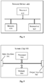
- Fig. 5 is a schematic structural diagram illustrating a system chip according to an embodiment of the disclosure.
- the system chip 500 as shown in Fig. 5 includes an input interface 501, an output interface 502, at least one processor 503, and a memory 504.
- the input interface 501, the output interface 502, the processor 503, and the memory 504 are interconnected by an internal connection path.
- the processor 503 is configured to execute codes in the memory 504.
- the processor 503 can implement the method 200 performed by the terminal device in the method embodiments. For the sake of brevity, it will not be repeated here.
- a unit partition is merely a logic functional partition.
- additional manners of partitioning may be available.
- multiple units or components may be combined or integrated into another system, or some features may be ignored or not executed.
- the displayed or discussed mutual couplings or direct couplings or communication connections may be implemented by using some interfaces.
- the indirect couplings or communication connections between the apparatuses or units may be implemented in electronic, mechanical, or other forms.
- the units described as separate parts may or may not be physically separate, and parts displayed as units may or may not be physical units, i.e., either located at one place or distributed on a plurality of network units. Units may be selected in part or in whole according to actual needs to implement the objectives of the embodiments of the present disclosure.
- functional units in the embodiments of the present disclosure may be integrated into one processing unit, or each of the units may exist alone physically, or two or more units are integrated into one unit.
- the functions When the functions are implemented in the form of a software functional unit and sold or used as an independent product, the functions may be stored in a computer-readable storage medium.
- the technical solution of the embodiments of the present disclosure in essence or that part of contribution to the prior art or a part of the technical solution may be embodied in the form of software products, which may be stored in a storage medium, comprising some instructions to cause a computer device (a personal computer, a server or a network device and so on) to execute all or a part of steps of the method as recited in the embodiments of the present disclosure.
- the aforementioned storage medium includes: a USB flash disk, a mobile hard disk, a read only memory (ROM), a random access memory (RAM), a magnetic disk or an optical disk and other media capable of storing program codes.
Landscapes
- Engineering & Computer Science (AREA)
- Computer Networks & Wireless Communication (AREA)
- Signal Processing (AREA)
- Mobile Radio Communication Systems (AREA)
Applications Claiming Priority (1)
| Application Number | Priority Date | Filing Date | Title |
|---|---|---|---|
| PCT/CN2017/097673 WO2019033302A1 (fr) | 2017-08-16 | 2017-08-16 | Procédé d'émission de signaux et dispositif terminal |
Publications (2)
| Publication Number | Publication Date |
|---|---|
| EP3627903A1 true EP3627903A1 (fr) | 2020-03-25 |
| EP3627903A4 EP3627903A4 (fr) | 2020-05-27 |
Family
ID=65361761
Family Applications (1)
| Application Number | Title | Priority Date | Filing Date |
|---|---|---|---|
| EP17921769.0A Withdrawn EP3627903A4 (fr) | 2017-08-16 | 2017-08-16 | Procédé d'émission de signaux et dispositif terminal |
Country Status (14)
| Country | Link |
|---|---|
| US (2) | US10999803B2 (fr) |
| EP (1) | EP3627903A4 (fr) |
| JP (1) | JP7203815B2 (fr) |
| KR (1) | KR102343593B1 (fr) |
| CN (2) | CN111526569B (fr) |
| AU (1) | AU2017427721A1 (fr) |
| BR (1) | BR112019026853A2 (fr) |
| CA (1) | CA3065411A1 (fr) |
| IL (1) | IL270959A (fr) |
| PH (1) | PH12019502708A1 (fr) |
| RU (1) | RU2743102C1 (fr) |
| SG (1) | SG11201911473SA (fr) |
| WO (1) | WO2019033302A1 (fr) |
| ZA (1) | ZA202000123B (fr) |
Cited By (1)
| Publication number | Priority date | Publication date | Assignee | Title |
|---|---|---|---|---|
| WO2021233275A1 (fr) * | 2020-05-21 | 2021-11-25 | Qualcomm Incorporated | Configuration de liaison montante pour la communication de signaux sur la base de multiples panneaux d'antenne |
Families Citing this family (5)
| Publication number | Priority date | Publication date | Assignee | Title |
|---|---|---|---|---|
| CN111510271B (zh) * | 2018-02-08 | 2022-01-28 | Oppo广东移动通信有限公司 | 传输信息的方法、接收信息的方法、终端设备和网络设备 |
| EP3764708A4 (fr) * | 2018-03-07 | 2021-03-10 | Guangdong Oppo Mobile Telecommunications Corp., Ltd. | Procédé de transmission de données sur une partie de bande passante, dispositif terminal et dispositif de réseau |
| CN112153740B (zh) | 2019-06-28 | 2025-03-11 | 华为技术有限公司 | 一种通信方法及装置 |
| CN113541879B (zh) * | 2020-04-16 | 2022-09-02 | 维沃移动通信有限公司 | 信息传输方法及设备 |
| WO2023102925A1 (fr) * | 2021-12-10 | 2023-06-15 | Oppo广东移动通信有限公司 | Procédé et appareil de distribution de puissance, dispositif et support de stockage |
Family Cites Families (53)
| Publication number | Priority date | Publication date | Assignee | Title |
|---|---|---|---|---|
| US8107987B2 (en) * | 2007-02-14 | 2012-01-31 | Qualcomm Incorporated | Apparatus and method for uplink power control of wireless communications |
| ATE515837T1 (de) * | 2007-05-29 | 2011-07-15 | Ericsson Telefon Ab L M | Technik für aufwärtsdatenübertragungen in kommunikationsnetzen |
| JP4569608B2 (ja) * | 2007-08-15 | 2010-10-27 | ソニー株式会社 | 非水電解質二次電池 |
| US8531975B2 (en) | 2008-07-08 | 2013-09-10 | Lg Electronics Inc. | Method and apparatus for controlling uplink power in a wireless communication system |
| KR101697596B1 (ko) * | 2009-01-29 | 2017-01-18 | 엘지전자 주식회사 | 전송 전력을 제어하는 방법 및 이를 위한 장치 |
| US8724488B2 (en) * | 2009-03-17 | 2014-05-13 | Interdigital Patent Holdings, Inc. | Method and apparatus for power control of sounding reference signal (SRS) transmission |
| JP5023170B2 (ja) | 2009-04-27 | 2012-09-12 | 株式会社エヌ・ティ・ティ・ドコモ | ユーザ装置、基地局装置及び通信制御方法 |
| JP5111536B2 (ja) * | 2009-04-27 | 2013-01-09 | 株式会社エヌ・ティ・ティ・ドコモ | ユーザ装置、基地局装置及び通信制御方法 |
| CN102428739B (zh) * | 2009-05-20 | 2016-05-11 | 瑞典爱立信有限公司 | 用于传递优先级信息以便在调度数据的传送中使用的系统和方法 |
| JP4907700B2 (ja) * | 2009-07-10 | 2012-04-04 | 株式会社エヌ・ティ・ティ・ドコモ | 無線局、送信局及び周波数帯共用方法 |
| CN101998596B (zh) * | 2009-08-17 | 2014-06-25 | 夏普株式会社 | 上行多输入多输出信道的功率控制方法 |
| EP2317815A1 (fr) * | 2009-11-02 | 2011-05-04 | Panasonic Corporation | Rapport de limite de puissance dans un système de communication utilisant une agrégation de support |
| CN102209374B (zh) * | 2010-03-30 | 2014-11-05 | 中国移动通信集团公司 | 一种上行功率控制信息指示方法及其装置 |
| US9144040B2 (en) | 2010-04-01 | 2015-09-22 | Futurewei Technologies, Inc. | System and method for uplink multi-antenna power control in a communications system |
| KR20110139078A (ko) * | 2010-06-22 | 2011-12-28 | 삼성전자주식회사 | 이동통신 시스템에서 역방향 전송 출력을 결정하는 방법 및 장치 |
| US9084209B2 (en) * | 2010-11-09 | 2015-07-14 | Qualcomm Incorporated | Carrier grouping for power headroom report |
| US8792432B2 (en) * | 2011-02-14 | 2014-07-29 | Broadcom Corporation | Prioritizing RACH message contents |
| KR20120121787A (ko) * | 2011-04-27 | 2012-11-06 | 주식회사 팬택 | 통신 시스템에서 기준신호 전송 전력 제어 장치 및 방법 |
| CN102821449A (zh) * | 2011-06-08 | 2012-12-12 | 中兴通讯股份有限公司 | 一种上行信号发射功率削减的方法和装置 |
| CN102843759B (zh) * | 2011-06-23 | 2016-03-02 | 华为技术有限公司 | 一种上行多入多出信道的功率控制方法和用户设备 |
| KR101748107B1 (ko) * | 2011-07-29 | 2017-06-15 | 후지쯔 가부시끼가이샤 | 파워 제어 방법 및 단말 장치 |
| US9325475B2 (en) * | 2011-08-05 | 2016-04-26 | Panasonic Intellectual Property Corporation Of America | Terminal, base station, transmission method and reception method in a heterogeneous network regarding comp control of channel information |
| US9014093B2 (en) * | 2011-11-02 | 2015-04-21 | Industrial Technology Research Institute | Direct communication method and direct communication device and coordinator device using the same |
| KR101867314B1 (ko) * | 2011-11-15 | 2018-06-15 | 주식회사 골드피크이노베이션즈 | 다중 요소 반송파 시스템에서 상향링크 전송전력의 제어장치 및 방법 |
| CN102573030B (zh) * | 2011-12-08 | 2014-11-05 | 电信科学技术研究院 | 一种上行功率控制方法及装置 |
| CN103200663B (zh) * | 2012-01-09 | 2016-03-09 | 华为技术有限公司 | 上行信道功率控制方法、装置及系统 |
| WO2013115714A1 (fr) * | 2012-01-31 | 2013-08-08 | Telefonaktiebolaget L M Ericsson (Publ) | Procédés, nœud de réseau et équipement d'utilisateur pour entrées multiples/sorties multiples liaison montante |
| CN103312461B (zh) * | 2012-03-16 | 2016-07-06 | 华为技术有限公司 | 一种上行多输入多输出系统中传输格式的选择方法及相关方法和设备 |
| CN103369650B (zh) * | 2012-03-26 | 2017-02-08 | 电信科学技术研究院 | 一种上行功率控制方法及用户设备 |
| CN103369647B (zh) * | 2012-04-06 | 2017-12-12 | 中兴通讯股份有限公司 | 多天线的功率分配方法及装置 |
| CN103369657B (zh) * | 2012-04-06 | 2017-05-24 | 中兴通讯股份有限公司 | 一种功率分配方法和通信节点 |
| WO2014019178A1 (fr) * | 2012-08-01 | 2014-02-06 | 华为技术有限公司 | Procédé et terminal de rapport d'informations de commande de liaison montante, et station de base |
| JP6159523B2 (ja) * | 2012-12-11 | 2017-07-05 | 株式会社Nttドコモ | ユーザ装置及び送信制御方法 |
| EP2944133B1 (fr) * | 2013-01-10 | 2022-09-07 | Telefonaktiebolaget LM Ericsson (publ) | Équipement utilisateur et procédé pour réguler la puissance de transmissions de liaison montante |
| WO2014136789A1 (fr) * | 2013-03-05 | 2014-09-12 | シャープ株式会社 | Dispositif de station de base, dispositif de terminal, circuit intégré et procédé de communication sans fil |
| CN105027657B (zh) * | 2013-03-05 | 2018-12-11 | 夏普株式会社 | 终端装置、基站装置、集成电路以及无线通信方法 |
| JP6456287B2 (ja) * | 2013-07-12 | 2019-01-23 | シャープ株式会社 | 端末装置、方法および集積回路 |
| WO2015021599A1 (fr) * | 2013-08-13 | 2015-02-19 | 富士通株式会社 | Procédé de commande de puissance de canal de liaison montante, équipement utilisateur et système de communication |
| US9264963B2 (en) * | 2013-08-21 | 2016-02-16 | Intel Corporation | User equipment and method for enhanced uplink power control |
| KR102207115B1 (ko) * | 2013-09-04 | 2021-01-25 | 엘지전자 주식회사 | 무선 통신 시스템에서 상향링크 전력을 제어하는 방법 및 장치 |
| KR101484059B1 (ko) * | 2013-09-17 | 2015-01-20 | 성균관대학교산학협력단 | 다중 전송 속도 파티셔닝 및 협력 전송을 이용한 고속 무선랜 통신 방법 및 무선랜 통신 장치 |
| CN105684498B (zh) * | 2013-11-01 | 2020-01-10 | 夏普株式会社 | 终端装置、基站装置以及方法 |
| CN104683082B (zh) * | 2013-12-03 | 2018-10-09 | 索尼公司 | 无线通信系统和在无线通信系统中进行无线通信的方法 |
| PL3100535T3 (pl) | 2014-01-29 | 2019-09-30 | Interdigital Patent Holdings, Inc. | Transmisje łącza uplink w komunikacji bezprzewodowej |
| EP3675566B1 (fr) * | 2014-01-29 | 2022-07-06 | InterDigital Patent Holdings, Inc. | Procédé et appareil d'accès et d'adaptation de liaisons pour transmissions sans fil à couverture améliorée |
| JP6298329B2 (ja) * | 2014-03-20 | 2018-03-20 | 株式会社Nttドコモ | ユーザ端末、無線基地局および無線通信方法 |
| WO2015168906A1 (fr) * | 2014-05-08 | 2015-11-12 | 富士通株式会社 | Procédé de régulation de puissance pour un canal de liaison montante, équipement utilisateur et système de communication |
| JP2015216440A (ja) * | 2014-05-08 | 2015-12-03 | 株式会社Nttドコモ | ユーザ端末、無線基地局、無線通信方法及び無線通信システム |
| US10455527B2 (en) * | 2014-08-08 | 2019-10-22 | Lg Electronics Inc. | Method and apparatus for transmitting and receiving wireless signal in wireless communication system |
| US10225808B2 (en) * | 2014-09-23 | 2019-03-05 | Lg Electronics Inc. | Method for controlling transmission power in unlicensed band and device using same |
| US9585102B2 (en) * | 2014-09-26 | 2017-02-28 | Kt Corporation | Method of controlling the transmission power of uplink channels and signals and apparatuses thereof |
| US10462783B2 (en) * | 2016-02-26 | 2019-10-29 | The Boeing Company | System and method for highly deterministic media access control |
| US10536904B2 (en) * | 2016-05-09 | 2020-01-14 | Ofinno, Llc | Parallel transmission in a wireless device and wireless network |
-
2017
- 2017-08-16 AU AU2017427721A patent/AU2017427721A1/en not_active Abandoned
- 2017-08-16 BR BR112019026853-7A patent/BR112019026853A2/pt not_active IP Right Cessation
- 2017-08-16 US US16/619,717 patent/US10999803B2/en active Active
- 2017-08-16 CA CA3065411A patent/CA3065411A1/fr active Pending
- 2017-08-16 SG SG11201911473SA patent/SG11201911473SA/en unknown
- 2017-08-16 KR KR1020207001901A patent/KR102343593B1/ko active Active
- 2017-08-16 CN CN202010279317.9A patent/CN111526569B/zh active Active
- 2017-08-16 JP JP2020502639A patent/JP7203815B2/ja active Active
- 2017-08-16 CN CN201780093538.3A patent/CN110999406A/zh active Pending
- 2017-08-16 WO PCT/CN2017/097673 patent/WO2019033302A1/fr not_active Ceased
- 2017-08-16 RU RU2019143096A patent/RU2743102C1/ru active
- 2017-08-16 EP EP17921769.0A patent/EP3627903A4/fr not_active Withdrawn
-
2019
- 2019-11-26 IL IL270959A patent/IL270959A/en unknown
- 2019-11-29 PH PH12019502708A patent/PH12019502708A1/en unknown
-
2020
- 2020-01-08 ZA ZA2020/00123A patent/ZA202000123B/en unknown
-
2021
- 2021-04-12 US US17/228,106 patent/US11503551B2/en active Active
Cited By (1)
| Publication number | Priority date | Publication date | Assignee | Title |
|---|---|---|---|---|
| WO2021233275A1 (fr) * | 2020-05-21 | 2021-11-25 | Qualcomm Incorporated | Configuration de liaison montante pour la communication de signaux sur la base de multiples panneaux d'antenne |
Also Published As
| Publication number | Publication date |
|---|---|
| US20210235387A1 (en) | 2021-07-29 |
| CN111526569B (zh) | 2024-05-03 |
| US20200205084A1 (en) | 2020-06-25 |
| RU2743102C1 (ru) | 2021-02-15 |
| EP3627903A4 (fr) | 2020-05-27 |
| CN110999406A (zh) | 2020-04-10 |
| IL270959A (en) | 2020-01-30 |
| CA3065411A1 (fr) | 2019-02-21 |
| JP7203815B2 (ja) | 2023-01-13 |
| JP2020534713A (ja) | 2020-11-26 |
| AU2017427721A1 (en) | 2019-12-19 |
| BR112019026853A2 (pt) | 2020-06-30 |
| ZA202000123B (en) | 2021-08-25 |
| KR20200038455A (ko) | 2020-04-13 |
| KR102343593B1 (ko) | 2021-12-28 |
| US10999803B2 (en) | 2021-05-04 |
| WO2019033302A1 (fr) | 2019-02-21 |
| SG11201911473SA (en) | 2020-01-30 |
| CN111526569A (zh) | 2020-08-11 |
| US11503551B2 (en) | 2022-11-15 |
| PH12019502708A1 (en) | 2020-12-07 |
Similar Documents
| Publication | Publication Date | Title |
|---|---|---|
| US11503551B2 (en) | Signal transmission method and terminal device | |
| US12262404B2 (en) | Information transmission method and apparatus under overlapping of multiple wireless transmissions in time domain | |
| EP3734847B1 (fr) | Procédé de configuration de ressource, appareil de communication et programme informatique | |
| US11071135B2 (en) | Uplink transmission method based on uplink reference signal, terminal, and network device | |
| EP3506698B1 (fr) | Procédé de communication, terminal et dispositif réseau | |
| KR20200033801A (ko) | 상향 전송 방법 및 단말기 디바이스 | |
| CN111163522A (zh) | 物理上行共享信道传输方法和终端设备 | |
| US20200296746A1 (en) | Method for transmitting information, method for receiving information, terminal device, and network device | |
| CN113170441B (zh) | 用于与多个传输接收点进行操作的上行链路控制信息的复用 | |
| US20240260040A1 (en) | Information transmission method and apparatus, device, and storage medium | |
| CN115088364A (zh) | 更新多个通信的调度 | |
| US12507209B2 (en) | Method for wireless communication and terminal device | |
| WO2023206458A1 (fr) | Attribution de ressources pour une transmission de pusch simultanée multi-panneaux | |
| CN118158732A (zh) | 非周期cli汇报方法及装置、计算机可读存储介质 | |
| CN110583067B (zh) | 无线通信方法、终端设备、网络设备和网络节点 | |
| WO2025111954A1 (fr) | Procédés et appareils pour une répétition de pusch msg5 | |
| US20250038815A1 (en) | Wireless communication methods, terminal devices and network devices | |
| WO2024093137A1 (fr) | Dispositifs et procédés de transmission pour autorisation configurée | |
| WO2024092512A1 (fr) | Amélioration pour une attribution dynamique annulant une autorisation configurée |
Legal Events
| Date | Code | Title | Description |
|---|---|---|---|
| STAA | Information on the status of an ep patent application or granted ep patent |
Free format text: STATUS: THE INTERNATIONAL PUBLICATION HAS BEEN MADE |
|
| PUAI | Public reference made under article 153(3) epc to a published international application that has entered the european phase |
Free format text: ORIGINAL CODE: 0009012 |
|
| STAA | Information on the status of an ep patent application or granted ep patent |
Free format text: STATUS: REQUEST FOR EXAMINATION WAS MADE |
|
| 17P | Request for examination filed |
Effective date: 20191217 |
|
| AK | Designated contracting states |
Kind code of ref document: A1 Designated state(s): AL AT BE BG CH CY CZ DE DK EE ES FI FR GB GR HR HU IE IS IT LI LT LU LV MC MK MT NL NO PL PT RO RS SE SI SK SM TR |
|
| AX | Request for extension of the european patent |
Extension state: BA ME |
|
| A4 | Supplementary search report drawn up and despatched |
Effective date: 20200429 |
|
| RIC1 | Information provided on ipc code assigned before grant |
Ipc: H04W 72/04 20090101ALI20200422BHEP Ipc: H04W 52/16 20090101ALI20200422BHEP Ipc: H04W 52/10 20090101ALI20200422BHEP Ipc: H04W 52/28 20090101ALI20200422BHEP Ipc: H04W 52/14 20090101ALI20200422BHEP Ipc: H04W 52/00 20090101AFI20200422BHEP Ipc: H04W 52/36 20090101ALI20200422BHEP Ipc: H04W 72/12 20090101ALI20200422BHEP |
|
| DAV | Request for validation of the european patent (deleted) | ||
| DAX | Request for extension of the european patent (deleted) | ||
| STAA | Information on the status of an ep patent application or granted ep patent |
Free format text: STATUS: EXAMINATION IS IN PROGRESS |
|
| 17Q | First examination report despatched |
Effective date: 20210122 |
|
| STAA | Information on the status of an ep patent application or granted ep patent |
Free format text: STATUS: THE APPLICATION IS DEEMED TO BE WITHDRAWN |
|
| 18D | Application deemed to be withdrawn |
Effective date: 20231011 |