EP3628344A1 - Blutpumpe - Google Patents
Blutpumpe Download PDFInfo
- Publication number
- EP3628344A1 EP3628344A1 EP19202306.7A EP19202306A EP3628344A1 EP 3628344 A1 EP3628344 A1 EP 3628344A1 EP 19202306 A EP19202306 A EP 19202306A EP 3628344 A1 EP3628344 A1 EP 3628344A1
- Authority
- EP
- European Patent Office
- Prior art keywords
- blood pump
- rotor
- pump according
- stator
- gap
- Prior art date
- Legal status (The legal status is an assumption and is not a legal conclusion. Google has not performed a legal analysis and makes no representation as to the accuracy of the status listed.)
- Granted
Links
Images


Classifications
-
- A—HUMAN NECESSITIES
- A61—MEDICAL OR VETERINARY SCIENCE; HYGIENE
- A61M—DEVICES FOR INTRODUCING MEDIA INTO, OR ONTO, THE BODY; DEVICES FOR TRANSDUCING BODY MEDIA OR FOR TAKING MEDIA FROM THE BODY; DEVICES FOR PRODUCING OR ENDING SLEEP OR STUPOR
- A61M60/00—Blood pumps; Devices for mechanical circulatory actuation; Balloon pumps for circulatory assistance
- A61M60/40—Details relating to driving
- A61M60/403—Details relating to driving for non-positive displacement blood pumps
- A61M60/408—Details relating to driving for non-positive displacement blood pumps the force acting on the blood contacting member being mechanical, e.g. transmitted by a shaft or cable
- A61M60/411—Details relating to driving for non-positive displacement blood pumps the force acting on the blood contacting member being mechanical, e.g. transmitted by a shaft or cable generated by an electromotor
- A61M60/414—Details relating to driving for non-positive displacement blood pumps the force acting on the blood contacting member being mechanical, e.g. transmitted by a shaft or cable generated by an electromotor transmitted by a rotating cable, e.g. for blood pumps mounted on a catheter
-
- A—HUMAN NECESSITIES
- A61—MEDICAL OR VETERINARY SCIENCE; HYGIENE
- A61M—DEVICES FOR INTRODUCING MEDIA INTO, OR ONTO, THE BODY; DEVICES FOR TRANSDUCING BODY MEDIA OR FOR TAKING MEDIA FROM THE BODY; DEVICES FOR PRODUCING OR ENDING SLEEP OR STUPOR
- A61M60/00—Blood pumps; Devices for mechanical circulatory actuation; Balloon pumps for circulatory assistance
- A61M60/10—Location thereof with respect to the patient's body
- A61M60/122—Implantable pumps or pumping devices, i.e. the blood being pumped inside the patient's body
- A61M60/126—Implantable pumps or pumping devices, i.e. the blood being pumped inside the patient's body implantable via, into, inside, in line, branching on, or around a blood vessel
- A61M60/13—Implantable pumps or pumping devices, i.e. the blood being pumped inside the patient's body implantable via, into, inside, in line, branching on, or around a blood vessel by means of a catheter allowing explantation, e.g. catheter pumps temporarily introduced via the vascular system
-
- A—HUMAN NECESSITIES
- A61—MEDICAL OR VETERINARY SCIENCE; HYGIENE
- A61M—DEVICES FOR INTRODUCING MEDIA INTO, OR ONTO, THE BODY; DEVICES FOR TRANSDUCING BODY MEDIA OR FOR TAKING MEDIA FROM THE BODY; DEVICES FOR PRODUCING OR ENDING SLEEP OR STUPOR
- A61M60/00—Blood pumps; Devices for mechanical circulatory actuation; Balloon pumps for circulatory assistance
- A61M60/10—Location thereof with respect to the patient's body
- A61M60/122—Implantable pumps or pumping devices, i.e. the blood being pumped inside the patient's body
- A61M60/126—Implantable pumps or pumping devices, i.e. the blood being pumped inside the patient's body implantable via, into, inside, in line, branching on, or around a blood vessel
- A61M60/135—Implantable pumps or pumping devices, i.e. the blood being pumped inside the patient's body implantable via, into, inside, in line, branching on, or around a blood vessel inside a blood vessel, e.g. using grafting
-
- A—HUMAN NECESSITIES
- A61—MEDICAL OR VETERINARY SCIENCE; HYGIENE
- A61M—DEVICES FOR INTRODUCING MEDIA INTO, OR ONTO, THE BODY; DEVICES FOR TRANSDUCING BODY MEDIA OR FOR TAKING MEDIA FROM THE BODY; DEVICES FOR PRODUCING OR ENDING SLEEP OR STUPOR
- A61M60/00—Blood pumps; Devices for mechanical circulatory actuation; Balloon pumps for circulatory assistance
- A61M60/10—Location thereof with respect to the patient's body
- A61M60/122—Implantable pumps or pumping devices, i.e. the blood being pumped inside the patient's body
- A61M60/126—Implantable pumps or pumping devices, i.e. the blood being pumped inside the patient's body implantable via, into, inside, in line, branching on, or around a blood vessel
- A61M60/148—Implantable pumps or pumping devices, i.e. the blood being pumped inside the patient's body implantable via, into, inside, in line, branching on, or around a blood vessel in line with a blood vessel using resection or like techniques, e.g. permanent endovascular heart assist devices
-
- A—HUMAN NECESSITIES
- A61—MEDICAL OR VETERINARY SCIENCE; HYGIENE
- A61M—DEVICES FOR INTRODUCING MEDIA INTO, OR ONTO, THE BODY; DEVICES FOR TRANSDUCING BODY MEDIA OR FOR TAKING MEDIA FROM THE BODY; DEVICES FOR PRODUCING OR ENDING SLEEP OR STUPOR
- A61M60/00—Blood pumps; Devices for mechanical circulatory actuation; Balloon pumps for circulatory assistance
- A61M60/20—Type thereof
- A61M60/205—Non-positive displacement blood pumps
- A61M60/216—Non-positive displacement blood pumps including a rotating member acting on the blood, e.g. impeller
-
- A—HUMAN NECESSITIES
- A61—MEDICAL OR VETERINARY SCIENCE; HYGIENE
- A61M—DEVICES FOR INTRODUCING MEDIA INTO, OR ONTO, THE BODY; DEVICES FOR TRANSDUCING BODY MEDIA OR FOR TAKING MEDIA FROM THE BODY; DEVICES FOR PRODUCING OR ENDING SLEEP OR STUPOR
- A61M60/00—Blood pumps; Devices for mechanical circulatory actuation; Balloon pumps for circulatory assistance
- A61M60/20—Type thereof
- A61M60/205—Non-positive displacement blood pumps
- A61M60/216—Non-positive displacement blood pumps including a rotating member acting on the blood, e.g. impeller
- A61M60/237—Non-positive displacement blood pumps including a rotating member acting on the blood, e.g. impeller the blood flow through the rotating member having mainly axial components, e.g. axial flow pumps
-
- A—HUMAN NECESSITIES
- A61—MEDICAL OR VETERINARY SCIENCE; HYGIENE
- A61M—DEVICES FOR INTRODUCING MEDIA INTO, OR ONTO, THE BODY; DEVICES FOR TRANSDUCING BODY MEDIA OR FOR TAKING MEDIA FROM THE BODY; DEVICES FOR PRODUCING OR ENDING SLEEP OR STUPOR
- A61M60/00—Blood pumps; Devices for mechanical circulatory actuation; Balloon pumps for circulatory assistance
- A61M60/40—Details relating to driving
- A61M60/403—Details relating to driving for non-positive displacement blood pumps
- A61M60/419—Details relating to driving for non-positive displacement blood pumps the force acting on the blood contacting member being permanent magnetic, e.g. from a rotating magnetic coupling between driving and driven magnets
-
- A—HUMAN NECESSITIES
- A61—MEDICAL OR VETERINARY SCIENCE; HYGIENE
- A61M—DEVICES FOR INTRODUCING MEDIA INTO, OR ONTO, THE BODY; DEVICES FOR TRANSDUCING BODY MEDIA OR FOR TAKING MEDIA FROM THE BODY; DEVICES FOR PRODUCING OR ENDING SLEEP OR STUPOR
- A61M60/00—Blood pumps; Devices for mechanical circulatory actuation; Balloon pumps for circulatory assistance
- A61M60/40—Details relating to driving
- A61M60/403—Details relating to driving for non-positive displacement blood pumps
- A61M60/422—Details relating to driving for non-positive displacement blood pumps the force acting on the blood contacting member being electromagnetic, e.g. using canned motor pumps
-
- A—HUMAN NECESSITIES
- A61—MEDICAL OR VETERINARY SCIENCE; HYGIENE
- A61M—DEVICES FOR INTRODUCING MEDIA INTO, OR ONTO, THE BODY; DEVICES FOR TRANSDUCING BODY MEDIA OR FOR TAKING MEDIA FROM THE BODY; DEVICES FOR PRODUCING OR ENDING SLEEP OR STUPOR
- A61M60/00—Blood pumps; Devices for mechanical circulatory actuation; Balloon pumps for circulatory assistance
- A61M60/80—Constructional details other than related to driving
- A61M60/802—Constructional details other than related to driving of non-positive displacement blood pumps
- A61M60/81—Pump housings
-
- A—HUMAN NECESSITIES
- A61—MEDICAL OR VETERINARY SCIENCE; HYGIENE
- A61M—DEVICES FOR INTRODUCING MEDIA INTO, OR ONTO, THE BODY; DEVICES FOR TRANSDUCING BODY MEDIA OR FOR TAKING MEDIA FROM THE BODY; DEVICES FOR PRODUCING OR ENDING SLEEP OR STUPOR
- A61M60/00—Blood pumps; Devices for mechanical circulatory actuation; Balloon pumps for circulatory assistance
- A61M60/80—Constructional details other than related to driving
- A61M60/802—Constructional details other than related to driving of non-positive displacement blood pumps
- A61M60/81—Pump housings
- A61M60/812—Vanes or blades, e.g. static flow guides
-
- A—HUMAN NECESSITIES
- A61—MEDICAL OR VETERINARY SCIENCE; HYGIENE
- A61M—DEVICES FOR INTRODUCING MEDIA INTO, OR ONTO, THE BODY; DEVICES FOR TRANSDUCING BODY MEDIA OR FOR TAKING MEDIA FROM THE BODY; DEVICES FOR PRODUCING OR ENDING SLEEP OR STUPOR
- A61M60/00—Blood pumps; Devices for mechanical circulatory actuation; Balloon pumps for circulatory assistance
- A61M60/80—Constructional details other than related to driving
- A61M60/802—Constructional details other than related to driving of non-positive displacement blood pumps
- A61M60/818—Bearings
- A61M60/825—Contact bearings, e.g. ball-and-cup or pivot bearings
-
- A—HUMAN NECESSITIES
- A61—MEDICAL OR VETERINARY SCIENCE; HYGIENE
- A61M—DEVICES FOR INTRODUCING MEDIA INTO, OR ONTO, THE BODY; DEVICES FOR TRANSDUCING BODY MEDIA OR FOR TAKING MEDIA FROM THE BODY; DEVICES FOR PRODUCING OR ENDING SLEEP OR STUPOR
- A61M60/00—Blood pumps; Devices for mechanical circulatory actuation; Balloon pumps for circulatory assistance
- A61M60/80—Constructional details other than related to driving
- A61M60/802—Constructional details other than related to driving of non-positive displacement blood pumps
- A61M60/827—Sealings between moving parts
- A61M60/829—Sealings between moving parts having a purge fluid supply
-
- A—HUMAN NECESSITIES
- A61—MEDICAL OR VETERINARY SCIENCE; HYGIENE
- A61M—DEVICES FOR INTRODUCING MEDIA INTO, OR ONTO, THE BODY; DEVICES FOR TRANSDUCING BODY MEDIA OR FOR TAKING MEDIA FROM THE BODY; DEVICES FOR PRODUCING OR ENDING SLEEP OR STUPOR
- A61M60/00—Blood pumps; Devices for mechanical circulatory actuation; Balloon pumps for circulatory assistance
- A61M60/80—Constructional details other than related to driving
- A61M60/855—Constructional details other than related to driving of implantable pumps or pumping devices
- A61M60/857—Implantable blood tubes
-
- A—HUMAN NECESSITIES
- A61—MEDICAL OR VETERINARY SCIENCE; HYGIENE
- A61M—DEVICES FOR INTRODUCING MEDIA INTO, OR ONTO, THE BODY; DEVICES FOR TRANSDUCING BODY MEDIA OR FOR TAKING MEDIA FROM THE BODY; DEVICES FOR PRODUCING OR ENDING SLEEP OR STUPOR
- A61M2205/00—General characteristics of the apparatus
- A61M2205/02—General characteristics of the apparatus characterised by a particular materials
- A61M2205/0211—Ceramics
-
- A—HUMAN NECESSITIES
- A61—MEDICAL OR VETERINARY SCIENCE; HYGIENE
- A61M—DEVICES FOR INTRODUCING MEDIA INTO, OR ONTO, THE BODY; DEVICES FOR TRANSDUCING BODY MEDIA OR FOR TAKING MEDIA FROM THE BODY; DEVICES FOR PRODUCING OR ENDING SLEEP OR STUPOR
- A61M2205/00—General characteristics of the apparatus
- A61M2205/02—General characteristics of the apparatus characterised by a particular materials
- A61M2205/0238—General characteristics of the apparatus characterised by a particular materials the material being a coating or protective layer
-
- A—HUMAN NECESSITIES
- A61—MEDICAL OR VETERINARY SCIENCE; HYGIENE
- A61M—DEVICES FOR INTRODUCING MEDIA INTO, OR ONTO, THE BODY; DEVICES FOR TRANSDUCING BODY MEDIA OR FOR TAKING MEDIA FROM THE BODY; DEVICES FOR PRODUCING OR ENDING SLEEP OR STUPOR
- A61M2205/00—General characteristics of the apparatus
- A61M2205/10—General characteristics of the apparatus with powered movement mechanisms
- A61M2205/103—General characteristics of the apparatus with powered movement mechanisms rotating
-
- A—HUMAN NECESSITIES
- A61—MEDICAL OR VETERINARY SCIENCE; HYGIENE
- A61M—DEVICES FOR INTRODUCING MEDIA INTO, OR ONTO, THE BODY; DEVICES FOR TRANSDUCING BODY MEDIA OR FOR TAKING MEDIA FROM THE BODY; DEVICES FOR PRODUCING OR ENDING SLEEP OR STUPOR
- A61M2205/00—General characteristics of the apparatus
- A61M2205/36—General characteristics of the apparatus related to heating or cooling
- A61M2205/3606—General characteristics of the apparatus related to heating or cooling cooled
Definitions
- the application relates to a blood pump according to the preamble of claim 1.
- the application relates to a blood pump with a motor.
- Blood pumps with a proximal and a distal end and a catheter arranged between them are known from the prior art, in which a flexible drive shaft is guided in an interior of the catheter.
- Such blood pumps typically have a pump head at their distal end, which comprises a foldable housing and a foldable conveying element, the conveying element being connected to a distal region of the drive shaft.
- Pump heads of this type can be guided to locations that are difficult to access. For example, such a pump head can be inserted through the aortic arch through the femoral artery into an area of a patient's aortic valve in order to deliver blood from the left ventricle of the heart to the aorta.
- the drive shaft is driven at the proximal end of the blood pump by a motor, which is typically outside the patient's body.
- a blood pump is for example in the publication EP 2 868 331 A2 described.
- the publication US 4,895,557 discloses a motor assembly for driving a blood pump.
- This motor arrangement comprises a sterilizable and fluid-tight rotor housing, in which the rotor is located.
- the rotor housing is designed to be guided into a recess in a stator housing in such a way that the rotor is surrounded by a stator. After operation, the rotor housing can be pulled out of the recess in the stator housing and disposed of.
- a disadvantage of such a motor arrangement is that it has a comparatively large volume, which can cause problems in particular when the motor arrangement is attached to a patient's leg. In addition, such a motor arrangement can lead to considerable undesired heat generation during operation. Another disadvantage is that assembly of the system can result in considerable contamination of the stator, for example due to impurities on a user's gloves, which may require complex cleaning and sterilization of the reusable stator.
- the object of the present application is to propose a blood pump which is simple to use and which overcomes the above-mentioned disadvantages of known devices.
- the proposed blood pump comprises a flexible drive shaft guided in a catheter, a delivery element connected to the drive shaft in a distal region of the drive shaft, and a motor, the motor comprising a stator and a rotor rotatably mounted in the stator.
- the stator comprises a winding and the rotor a rotor magnet.
- the drive shaft is at a proximal end of the drive shaft connected to the rotor.
- the stator and the rotor are permanently connected to one another and form a gap which is delimited by the rotor and the stator.
- the proposed blood pump allows a compact design.
- the stator and the rotor form a unit that can be connected to one another, for example, in a force-fitting or material-locking manner.
- the compact design means that the motor can be lightweight, which means that a motor that may be attached to a patient's leg represents a lower load.
- the winding can have an inner radius that corresponds to a maximum of 1.5 times, preferably a maximum of 1.25 times, particularly preferably a maximum of 1.15 times, an outer radius of the rotor magnet.
- the magnetic air gap is given by the distance between the winding and the rotor magnet. A small distance between the rotor magnet and the winding allows an efficient conversion of electrical power into pump power, so that heat losses in the motor can be kept low when operating with a desired pump power. Since in the proposed motor, due to the one-piece construction, no housing parts have to be provided in the magnetic air gap, a small distance between the winding and the rotor magnet can be achieved compared to designs in which the stator and the rotor are housed individually. With an inner radius of the winding of 6 mm, the outer radius of the rotor magnet can be, for example, more than 5.25 mm.
- a radial distance between the winding and the rotor magnet can be a maximum of 2 mm, preferably a maximum of 1.25 mm, particularly preferably a maximum of 0.75 mm.
- the gap typically has an annular cross section.
- the gap has a width which corresponds to a width of the magnetic air gap or which is less than the width of the magnetic air gap. It can be provided that the gap has a maximum width of 1 mm, preferably a maximum 0.5 mm, particularly preferably a maximum of 0.25 mm. It can also be provided that the gap has a width of at least 0.1 mm, preferably at least 0.15 mm, particularly preferably at least 0.2 mm.
- a flushing opening can be provided which is in fluid communication with the gap.
- the flushing opening can be in fluid communication with a flushing connection.
- a flushing connection can be arranged, for example, on a proximal end of the motor.
- the gap is in fluid communication with an intermediate space formed between the catheter and the drive shaft.
- a flushing liquid can be flushed through the gap into the space between the drive shaft and the catheter through the flushing connection. Lubrication of the drive shaft in the catheter can thereby be achieved.
- a rinsing fluid can also be passed into the patient's body through the rinsing port, the gap and the space between the catheter and the drive shaft.
- a glucose solution can be used as the rinsing liquid.
- the rinsing liquid is washed around the rotor from a proximal end to a distal end. Provision can also be made for the flushing liquid to wash around the rotor from its distal to its proximal end.
- catheters with several lumens so that backwashing and backwashing can be achieved, as is the case, for example, in the document US 4,895,557 is described.
- Two or more connections for the rinsing liquid can be provided on the motor.
- the gap has a minimum width of 0.05 mm in order to ensure a reliable flow of the rinsing liquid through the gap.
- the winding is cast into a casting compound. Potting the winding with a potting compound is suitable for closing and leveling any depressions that may be present on a surface of the winding.
- the potting compound can comprise a thin-viscous material which is suitable for flowing into the depressions and filling them.
- the casting compound forms a part of the stator that delimits the gap.
- a largely smooth boundary surface of the gap can be achieved by the potting compound.
- the potting compound can comprise epoxy resin, for example.
- the potting compound has, for example, aluminum oxide, iron powder or other heat-conducting substances for improved heat transfer.
- the potting compound can ensure that a reduced number of air bubbles adheres to the stator after the gap has been vented.
- the potting compound can prevent damage or corrosion of the winding by a rinsing liquid or possibly transported particles by the rinsing liquid. In addition, the potting compound can prevent the particles from settling on the winding.
- the potting compound has biocompatible material.
- the potting compound is typically made entirely of biocompatible material so that no toxic substances are released to the patient via the rinsing connection.
- the winding is coated with parylene.
- the stator has a fluid-tight sleeve with an essentially ring-shaped cross section, through which the gap is delimited.
- the sleeve can separate the winding of the stator from the rinsing liquid. This can prevent damage to the winding from the washing liquid.
- the sleeve forms a part of the stator that delimits the gap.
- the sleeve can also be designed in such a way that, in addition to the winding, other motor parts are also separated from the flushing liquid by the sleeve and are thus prevented from being damaged. For example, solder joints located in the motor can be protected from corrosion by the sleeve.
- the sleeve can comprise, for example, a plastic, in particular polyether ether ketone or polyethylene, or glass. It can also be provided that the sleeve is formed from an elastic plastic, which comprises, for example, polyethylene.
- the sleeve serves to guide the flushing liquid and does not necessarily serve to mechanically stabilize the motor. It is therefore possible that the sleeve is thin-walled and / or made of a bendable material.
- an external shape of the engine or part of the engine is not determined by the shape of the sleeve. It can therefore be advantageous for the sleeve to cover the winding and / or the rotor only slightly in the axial direction. It can be provided, for example, that the sleeve has an extent in the axial direction that is less than 1.5 times an axial extent of the rotor magnet.
- the rotor is supported radially by at least one slide bearing.
- the rotor can be supported by two plain bearings.
- the at least one slide bearing can comprise, for example, non-magnetizable materials and / or ceramic materials, in particular aluminum oxide, zirconium oxide, yttrium-stabilized zirconium oxide or silicon nitride.
- the slide bearing can comprise, for example, steel, in particular implant steel.
- a biocompatible coating with diamond-like amorphous carbon can also be provided.
- the rotor can be supported radially by at least one ball bearing.
- the at least one ball bearing comprises non-magnetizable material.
- parts of the ball bearing on which abrasion occurs due to operation of the motor comprise non-magnetizable material or made of non-magnetizable material Material are made. This ensures that abraded material from the parts of the ball bearing does not adhere to ferromagnetic components of the motor. For example, ferromagnetic abrasion can be prevented from sticking to the rotor and thereby causing damage to the rotor. Furthermore, ferromagnetic abrasion can be prevented from damaging the winding or other components of the motor.
- the at least one ball bearing can have balls which comprise a ceramic material.
- the at least one ball bearing can have a cage which comprises a plastic.
- the cage can include polyethylene or polytetrafluoroethylene.
- the balls can also consist entirely of a ceramic material.
- the cage can be made entirely of a plastic.
- the rotor typically has a coating and / or a cover for protecting the rotor magnet. It may be the case that the coating and / or the cover forms a part of the rotor which delimits the gap.
- Both the coating and the cover can comprise biocompatible material or consist of biocompatible material.
- a coating with parylene or a biocompatible epoxy resin can be provided.
- a coating of diamond-like amorphous carbon can also be provided.
- the coating can have a thickness that is less than 100 ⁇ m, preferably less than 10 ⁇ m.
- the rotor can have a cover made of polyether ether ketone or stainless steel, for example.
- the blood pump can have a deployable pump head, which comprises the conveying element and a housing, the conveying element and the housing being designed in such a way that they unfold independently after a forced compression.
- a deployable pump head allows a relatively large design of the pump head and the conveying elements with a relatively small diameter of an opening in the tissue of a patient intended for the insertion of the blood pump.
- the pump is configured to pump blood from a ventricle into a patient's blood vessel when the motor is outside of a Body of the patient is arranged.
- the motor can, for example, be set up for attachment to a thigh of the patient.
- the flexible drive shaft has a sufficient length, which depends on the patient's anatomy.
- the flexible shaft typically has a length of at least 50 cm, preferably at least 90 cm.
- a maximum length of the flexible drive shaft is 200 cm, preferably 150 cm.
- the application also relates to an operating method for the proposed blood pump.
- a touchable surface of a housing of the motor heats up to a temperature of not more than 60 ° C., preferably not more than 48 ° C., particularly preferably not, during a continuous operation at a speed of 15,000, preferably at least 30,000, revolutions per minute more than 43 ° C.
- a touchable surface of a housing of the motor heats up to a temperature of not more than 60 ° C., preferably not more than 48 ° C., particularly preferably not, during a continuous operation at a speed of 15,000, preferably at least 30,000, revolutions per minute more than 43 ° C.
- the motor housing does not become too hot during operation.
- an operating method in which touchable surfaces of the housing of the motor during a permanent operation of the blood pump at a delivery rate of at least 1 l / min, preferably at least 2 l / min, to a temperature of not more than 60 ° C. preferably not more than 48 ° C, particularly preferably not more than 43 ° C.
- the blood pump for draining during operation caused heat a heat sink, for example with cooling fins, which are thermally connected to the engine, or has a heat pipe. It can also be provided that the blood pump is set up to emit heat to a patient's tissue, for example via the skin of the thigh.
- the blood pump can be delivered sterile packed with all the components described.
- the blood pump can be sterilized, for example, by means of gamma sterilization or using ethylene oxide. After using the blood pump, it can be completely disposed of. In the proposed blood pump, repeated cleaning or sterilization of parts of the blood pump, in particular of the motor, by a user is therefore unnecessary.
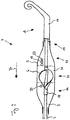
- FIG. 1 schematically shows a pump arrangement 1.
- the pump arrangement 1 comprises a catheter 2, in which a flexible drive shaft 3 is guided.
- the catheter 2 is connected to a pump head 4.
- This pump head 4 comprises a housing 5 and a conveying element 6 arranged in the housing 5, which can be driven via the drive shaft 3 with a motor 7 connected to the proximal end of the drive shaft 3.
- the pump head 4 and the catheter 2 and the drive shaft 3 are over a sluice 8 is inserted into the femoral artery 9 such that the pump head 4 is located in the area of the left ventricle 10 in the area of the aortic valve 11.
- the drive shaft 3 is driven by the motor 7 and the pump arrangement 1 conveys blood from the left ventricle 10 into the aorta 12.
- a conveying direction of the pump arrangement 1 corresponds to the direction from a distal end 13 of the pump arrangement 1 to a proximal end 14 of the pump arrangement 1.
- the pump arrangement 1 can, however, also be set up for conveying blood in a direction from the proximal end 14 to the distal end 13 of the pump arrangement 1, which is suitable, for example, for right-heart support.
- the pump head 4 is in Fig. 2 shown schematically. Recurring features are provided with the same reference symbols in this and in the following figures.
- the pump head 4 comprises the conveying element 6 and the housing 5.
- the conveying element 6 is designed as a pump rotor with two flexible segments in the form of rotor blades.
- the drive shaft 3 is shown, which is mounted on a distal region 15 of the pump head 4.
- a so-called pig tail 17 is provided, which is made of an elastically deformable material.
- a cylindrical element 18 is rigidly connected to the drive shaft 3.
- the conveying element 6 is fastened on the cylindrical element 18.
- Both the conveying element 6 and the housing 5 are designed to be unfoldable in such a way that they unfold themselves after forced compression.
- the conveying element 6 is made of a plastic.
- the housing 5 is made of the shape memory material Nitinol. Because both the conveying element 6 and the housing 5 are designed to be unfoldable, the entire pump head 4 can be unfolded.
- the housing 5 is designed as a diamond grid 19 and has an elastic covering 21 made of polyurethane in a liquid-tight region 20.
- the elastic covering 21 covers an inside and an outside of the diamond grid 19 such that the diamond-shaped formed by the grid 19 Grid openings in the liquid-tight area 20 are closed liquid-tight by the elastic covering 21.
- the housing 5 has an inlet area 22 which is not covered by the elastic covering 21.
- the diamond-shaped grid openings form inlet openings, one of which is in Fig. 2 is provided by way of example with the reference number 23.
- the housing 5 has an outlet area 24, which is likewise not covered by the elastic covering 21. In the outlet area 24, the diamond-shaped grid openings form outlet openings, one of which is shown by way of example and provided with the reference symbol 25.
- the drive shaft 3 is driven by the motor 7, so that the conveying element 6 connected to the drive shaft 3 rotates about an axis of the drive shaft 3.
- the conveying element 6 connected to the drive shaft 3 rotates about an axis of the drive shaft 3.
- blood is conveyed into the housing 5 through the inlet openings of the inlet region 22 and then emerges from the housing 5 through the outlet openings of the outlet region 24. In this way, blood is conveyed in a conveying direction 26 by the pump arrangement 1.
- the elastic covering 21 does not completely surround an axial extension of the conveying element 6.
- the conveying element 6 instead protrudes partially into the outlet area 24, so that at least the outlet opening with the reference symbol 25 laterally, i.e. is arranged in the radial direction, next to the conveying element 6.
- the elastic covering 21, on the other hand, is designed at its distal end in such a way that the conveying element 6 does not protrude or does not protrude significantly into the inlet region 22 and is therefore not laterally surrounded by inlet openings.
- the elastic covering 21 and the conveying element 6 are designed and arranged with respect to one another such that approximately one third of the axial extent of the conveying element 6 is not surrounded by the elastic covering 21, which forms the liquid-tight region 20.
- the same proportion of the axial extent of the conveying element 6 is surrounded by the outlet region 24 in the example shown.
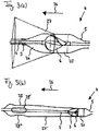
- the pump head 4 comprises an outflow element. This can be used as a discharge screen 27, as in Fig. 3 (a) is shown, or as a discharge hose 27 ', as in Fig. 3 (b) is shown to be executed.
- the in Fig. 3 (a) The outflow shield 27 shown is attached to the housing 5 in the liquid-tight region 20 of the housing 5.
- the outflow screen 27 has the shape of a jacket of a truncated cone and extends in the conveying direction 26 such that it is widened in the conveying direction 26.
- the delivery element 6 and the outlet area 24 are surrounded by the discharge screen 27. In another embodiment it can also be provided that the outlet area 24 is partially surrounded by the outflow screen 27.
- the pump head 4 in Fig. 3 (b) differs from that in Fig. 3 (a) shown pump head 4 only in that an outflow hose 27 'is provided instead of the outflow screen 27.
- This is fastened to the housing 5 in the liquid-tight area 20 and extends from there in the conveying direction 26.
- the outflow hose 27 ' is made of polyurethane and has openings 28, 28', 28 "in an area located in the conveying direction 26.
- the outlet area 24 is completely surrounded by the outflow tube 27 '.
- the outflow tube 27' is flexible and closes automatically when blood flow occurs opposite to the conveying direction 26, in that the outflow tube 27 'is connected to the catheter 2 and / or to the Housing 5 is pressed.
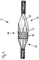
- Fig. 4 schematically shows the diamond grid 19 of the housing 5.
- the liquid-tight area 20 is shown with the elastic covering 21, and the inlet area 22 and the outlet area 24. Areas of the inlet area 22 and the outlet area 24 have a conical shape, while the liquid-tight area 20 im Is essentially tubular.
- the grid 19 has grid struts, one of which is identified by way of example with the reference number 45.
- the lattice struts 45 run in such a way that the substantially diamond-shaped lattice openings are larger both in the inlet area 22 and in the outlet area 24 than in the liquid-tight area 20.
- lattice struts are arranged on a side of the housing 5 facing away from the viewer Fig. 4 only indicated with dots.
- the grid struts 45 form a comparatively close-meshed grid 19 in the liquid-tight region 20.
- the grid 19 has thirty-two struts or, if the circumference is viewed at an axial position of the housing 5 with nodes, sixteen knots.
- Such a closely meshed grid 19 achieves a largely round cross section of the housing 5 in the liquid-tight region 20.
- the number of grating struts 45 along a circumference of the housing 5 is halved by bringing the grating struts together in pairs, so that the housing 5 in the corresponding areas has sixteen grating struts 45 along the circumference in which there are no nodes.
- the number of lattice struts 45 in the direction of the inlet region 22 and the outlet region 24 is then reduced again by bringing the lattice struts 45 together in pairs, so that the housing 5 has eight lattice struts 45 in these regions.
- a lattice 19 with larger lattice openings than in the liquid-tight region 20 is formed in the inlet region 22 and in the outlet region 24.
- the lattice struts 45 form a spiral structure in the conical regions of the outlet region 24 and the inlet region 22, which leads to a reliable unfolding of the pump head 4 when the pump head 4 is pushed out of a cannula.
- Fig. 5 shows a schematic view of the motor 7.
- the motor 7 is connected in the region of a stub shaft 29 to the catheter 2 which is glued into the stub shaft 29.
- the flexible drive shaft 3 is guided in the catheter 2.
- the motor 7 also has a rotor 30 which comprises a rotor magnet 31.
- the flexible drive shaft 3 is connected to the rotor 30 such that a torque is transmitted from the rotor 30 to the flexible drive shaft 3 when the rotor 30 rotates.
- the torque is transmitted to the conveying element 6 via the flexible drive shaft, so that the pump arrangement 1 is driven by the motor 7.
- the rotor 30 is axially supported by two bearings 32, 33.
- One of these bearings 33 is preloaded by a spring element 34 for axial stabilization of the rotor 30.
- the spring element 34 can be designed, for example, as a helical spring or as an annular spring.
- the bearings 32, 33 can each be designed as ball bearings or as plain bearings. If the bearings 32, 33 are designed as ball bearings, the bearings 32, 33 comprise balls made of ceramic and cages made of plastic, so that the ball bearings have non-magnetizable material.
- the rings of the bearings can be made of a magnetizable metal or a non-magnetizable material, for example. If the bearings 32, 33 are designed as plain bearings, they each comprise sliding partners made of DLC-coated implant steel and yttrium-stabilized zirconium oxide.
- the rotor magnet 31 has a biocompatible DLC coating 35.
- the motor 7 also has a stator 36.
- the stator 36 comprises a plurality of windings 37, which are electrically conductively connected to power connections 38.
- the stator 36 has return plates 39.
- the windings 37 are cast with a biocompatible epoxy resin, which contains heat-conducting aluminum oxide.
- a gap 40 with an annular cross section is formed between an inside of the coating of the windings 37 and an outside of the coating 35 of the rotor magnet 31.
- the gap 40 has a width of 0.2 mm.
- This gap 40 is in fluid communication with a flushing opening 41, which is connected to a flushing connection 42, the flushing connection 42 being arranged at a proximal end of the motor 7.
- the gap 40 is in fluid communication with an intermediate space formed between the drive shaft 3 and the catheter 2.
- a glucose solution can be flushed via the flushing connection 42 through the flushing opening 41 and the gap 40 and the intermediate space.
- the rotor 30 is flushed with the glucose solution during operation.
- a radial distance between an outside of the rotor magnet 31 and an inside of the windings 37 is 0.5 mm.
- An inner radius of the windings 37 corresponds to 1.1 times an outer radius of the rotor magnet 31.
- the stator 36 and the rotor 30 are non-detachably connected to one another and enclosed in a motor housing 43.
- the motor housing 43 can be connected to a handle or a heat sink, for example. Due to the small distance between the windings 37 and the rotor magnet 31, the motor can be operated very efficiently, so that both the motor housing 43 and any handle or heat sink connected to it are heated to less than 40 ° C. on their touchable surfaces when the pump arrangement 1 is operated at a speed of 32,000 revolutions per minute and a delivery rate of 2.5 l per minute.
- the in Fig. 6 Motor 7 'shown differs from that in Fig. 6 Motor 7 shown only in that the stator 36 in this embodiment has a liquid-tight sleeve 44 which delimits the gap 40.
- the width of the gap 40 is, for example, 0.15 mm or 0.22 mm.
- the sleeve 44 comprises polyether ether ketone and is magnetically inactive.
- the sleeve 44 is arranged such that, for example, the windings 37 and further parts of the stator 36 are separated by the sleeve 44 from the rinsing liquid which may flow through the gap 40.
- An expansion of the sleeve 44 in the axial direction is approximately 1.2 times an axial expansion of the rotor magnet 31.
Landscapes
- Health & Medical Sciences (AREA)
- Heart & Thoracic Surgery (AREA)
- Engineering & Computer Science (AREA)
- Cardiology (AREA)
- General Health & Medical Sciences (AREA)
- Public Health (AREA)
- Biomedical Technology (AREA)
- Hematology (AREA)
- Life Sciences & Earth Sciences (AREA)
- Animal Behavior & Ethology (AREA)
- Mechanical Engineering (AREA)
- Anesthesiology (AREA)
- Veterinary Medicine (AREA)
- Vascular Medicine (AREA)
- Transplantation (AREA)
- External Artificial Organs (AREA)
- Structures Of Non-Positive Displacement Pumps (AREA)
- Permanent Magnet Type Synchronous Machine (AREA)
- Permanent Field Magnets Of Synchronous Machinery (AREA)
- Connection Of Motors, Electrical Generators, Mechanical Devices, And The Like (AREA)
Abstract
Description
- Die Anmeldung betrifft eine Blutpumpe gemäß dem Oberbegriff des Anspruchs 1. Insbesondere betrifft die Anmeldung eine Blutpumpe mit einem Motor.
- Aus dem Stand der Technik sind Blutpumpen mit einem proximalen und einem distalen Ende sowie einem dazwischen angeordneten Katheter bekannt, bei denen eine flexible Antriebswelle in einem Innenraum des Katheters geführt wird. Solche Blutpumpen weisen an ihrem distalen Ende typischerweise einen Pumpenkopf auf, der ein faltbares Gehäuse und ein faltbares Förderelement umfasst, wobei das Förderelement mit einem distalen Bereich der Antriebswelle verbunden ist. Derartige Pumpenköpfe können an schwer zugängliche Orte geführt werden. Beispielsweise kann ein solcher Pumpenkopf durch die Femoralarterie über den Aortenbogen in einen Bereich der Aortenklappe eines Patienten eingeschoben werden, um dort Blut vom linken Ventrikel des Herzens in die Aorta zu befördern. Angetrieben wird die Antriebswelle am proximalen Ende der Blutpumpe durch einen Motor, welcher sich typischerweise außerhalb des Körpers des Patienten befindet. Eine derartige Blutpumpe ist beispielsweise in der Druckschrift
EP 2 868 331 A2 beschrieben. - Die Druckschrift
US 4,895,557 offenbart eine Motoranordnung zum Antrieb einer Blutpumpe. Diese Motoranordnung umfasst ein sterilisierbares und fluiddichtes Rotorgehäuse, in dem sich der Rotor befindet. Das Rotorgehäuse ist eingerichtet, zum Betrieb so in eine Aussparung eines Statorgehäuses geführt zu werden, dass der Rotor von einem Stator umgeben wird. Nach dem Betrieb kann das Rotorgehäuse aus der Aussparung des Statorgehäuses herausgezogen und entsorgt werden. - Ein Nachteil einer solchen Motoranordnung ist, dass diese vergleichsweise großvolumig ist, was insbesondere bei einer Befestigung der Motoranordnung an einem Bein eines Patienten Probleme verursachen kann. Darüber hinaus kann eine derartige Motoranordnung im Betrieb zu einer beträchtlichen ungewünschten Wärmeentwicklung führen. Ein weiterer Nachteil ist, dass es bei einer Montage des Systems zu erheblichen Verschmutzungen des Stators kommen kann, beispielsweise durch Unreinheiten an Handschuhen eines Anwenders, was gegebenenfalls eine aufwendige Reinigung und Sterilisation des wiederverwendbaren Stators erfordert.
- Der vorliegenden Anmeldung liegt die Aufgabe zugrunde, eine Blutpumpe vorzuschlagen, die einfach in der Handhabung ist und die die oben genannten Nachteile bekannter Vorrichtungen überwindet.
- Diese Aufgabe wird gelöst durch eine Blutpumpe mit den Merkmalen des Hauptanspruchs. Vorteilhafte Weiterbildungen ergeben sich mit den Merkmalen der abhängigen Ansprüche und der Ausführungsbeispiele.
- Die vorgeschlagene Blutpumpe umfasst eine in einem Katheter geführte und flexible Antriebswelle, ein in einem distalen Bereich der Antriebswelle mit der Antriebswelle verbundenes Förderelement und einen Motor, wobei der Motor einen Stator und einen in dem Stator drehbar gelagerten Rotor umfasst. Der Stator umfasst eine Wicklung und der Rotor einen Rotormagneten. Außerdem ist die Antriebswelle an einem proximalen Ende der Antriebswelle mit dem Rotor verbunden. Der Stator und der Rotor sind unlösbar miteinander verbunden und bilden einen Spalt aus, der durch den Rotor und den Stator begrenzt wird.
- Insbesondere gegenüber den aus dem Stand der Technik bekannten modularen Bauweisen von Motoren für Blutpumpen, bei denen der Rotor und der Stator für einen Anwender lösbar ausgeführt sind, erlaubt die vorgeschlagene Blutpumpe eine kompakte Bauweise. Bei dieser bilden der Stator und der Rotor eine Einheit, die beispielsweise kraft- oder stoffschlüssig miteinander verbunden sein kann. Durch die kompakte Bauweise kann ein geringes Gewicht des Motors erreicht werden, wodurch ein gegebenenfalls an einem Patientenbein befestigter Motor eine geringere Last darstellt.
- Die Wicklung kann einen Innenradius aufweisen, der maximal einem 1,5-fachen, bevorzugt maximal einem 1,25-fachen, besonders bevorzugt maximal einem 1,15-fachen, eines Außenradius des Rotormagneten entspricht. Durch den Abstand zwischen der Wicklung und dem Rotormagneten ist der magnetische Luftspalt gegeben. Ein geringer Abstand zwischen Rotormagnet und Wicklung erlaubt eine effiziente Umwandlung von elektrischer Leistung in Pumpleistung, so dass Wärmeverluste im Motor beim Betrieb mit einer gewünschten Pumpleistung gering gehalten werden können. Da bei dem vorgeschlagenen Motor durch die einteilige Bauweise keine Gehäuseteile in dem magnetischen Luftspalt vorgesehen sein müssen, kann ein geringer Abstand zwischen der Wicklung und dem Rotormagneten im Vergleich zu Bauformen erreicht werden, bei denen der Stator und der Rotor einzeln gehäust ausgeführt sind. Bei einem Innenradius der Wicklung von 6 mm kann der Außenradius des Rotormagneten beispielsweise mehr als 5,25 mm betragen.
- Beispielsweise kann ein radialer Abstand zwischen der Wicklung und dem Rotormagneten maximal 2 mm, vorzugsweise maximal 1,25 mm, besonders vorzugsweise maximal 0,75 mm, betragen.
- Der Spalt weist typischerweise einen ringförmigem Querschnitt auf. Der Spalt weist eine Breite auf, die einer Breite des magnetischen Luftspalts entspricht oder die geringer ist als die Breite des magnetischen Luftspalts. Es kann vorgesehen sein, dass der Spalt eine Breite von maximal 1 mm, vorzugsweise maximal 0,5 mm, besonders vorzugsweise maximal 0,25 mm, aufweist. Es kann auch vorgesehen sein, dass der Spalt eine Breite von mindestens 0,1 mm, vorzugsweise mindestens 0,15 mm, besonders vorzugsweise mindestens 0,2 mm, aufweist.
- Außerdem kann eine Spülöffnung vorgesehen sein, die in fluider Verbindung mit dem Spalt steht. Die Spülöffnung kann in fluider Verbindung mit einem Spülanschluss stehen. Ein solcher Spülanschluss kann beispielsweise an einem proximalen Ende des Motors angeordnet sein.
- Darüber hinaus kann es vorgesehen sein, dass der Spalt in fluider Verbindung mit einem zwischen dem Katheter und der Antriebswelle ausgebildeten Zwischenraum steht. Auf diese Weise kann durch den Spülanschluss eine Spülflüssigkeit durch den Spalt in den Zwischenraum zwischen der Antriebswelle und dem Katheter gespült werden. Dadurch kann ein Schmieren der Antriebswelle in dem Katheter erreicht werden. Darüber hinaus kann durch ein Einleiten der Spülflüssigkeit durch den Spülanschluss verhindert werden, dass Blut eines Patienten in den Motor und insbesondere in den Spalt gelangt. Es kann auch eine Spülflüssigkeit durch den Spülanschluss, den Spalt und den Zwischenraum zwischen dem Katheter und der Antriebswelle in den Körper des Patienten geleitet werden. Als Spülflüssigkeit kann beispielsweise eine Glukoselösung verwendet werden.
- Es kann vorgesehen sein, dass der Rotor von einem proximalen Ende zu einem distalen Ende von der Spülflüssigkeit umspült wird. Es kann auch vorgesehen sein, dass der Rotor von seinem distalen zu seinem proximalen Ende von der Spülflüssigkeit umspült wird.
- Es können auch Kathether mit mehreren Lumen Verwendung finden, so dass eine Hin- und eine Rückspülung erreicht werden kann, wie es beispielsweise in der Druckschrift
US 4,895,557 beschrieben ist. Hierbei können zwei oder mehrere Anschlüsse für die Spülflüssigkeit an dem Motor vorgesehen sein. - Es kann vorgesehen sein, dass der Spalt eine minimale Breite von 0,05 mm aufweist, um einen zuverlässigen Durchfluss der Spülflüssigkeit durch den Spalt zu gewährleisten.
- Es kann vorgesehen sein, dass die Wicklung in eine Vergussmasse eingegossen ist. Ein Vergießen der Wicklung mit einer Vergussmasse ist geeignet, gegebenenfalls vorhandene Vertiefungen an einer Oberfläche der Wicklung zu verschließen und zu nivellieren. Die Vergussmasse kann ein dünnviskoses Material umfassen, welches geeignet ist, in die Vertiefungen hineinzufließen und diese auszufüllen.
- Es kann vorgesehen sein, dass die Vergussmasse einen den Spalt begrenzenden Teil des Stators bildet. Durch die Vergussmasse kann eine weitgehend glatte Begrenzungsfläche des Spalts erreicht werden. Die Vergussmasse kann beispielsweise Epoxidharz umfassen. Darüber hinaus kann vorgesehen sein, dass die Vergussmasse beispielsweise Aluminiumoxid, Eisenpulver oder andere wärmeleitende Substanzen für eine verbesserte Wärmeübertragung aufweist. Zusätzlich kann durch die Vergussmasse erreicht werden, dass nach einem Entlüften des Spaltes eine verminderte Anzahl von Luftbläschen an dem Stator anhaftet.
- Durch die Vergussmasse kann eine Beschädigung oder Korrosion der Wicklung durch eine Spülflüssigkeit oder gegebenenfalls durch die Spülflüssigkeit transportierte Partikel verhindert werden. Darüber hinaus kann durch die Vergussmasse verhindert werden, dass sich die Partikel an der Wicklung absetzen.
- Außerdem kann es vorgesehen sein, dass die Vergussmasse biokompatibles Material aufweist. Typischerweise ist die Vergussmasse hierbei vollständig aus biokompatiblem Material gefertigt, damit keine toxischen Substanzen über den Spülanschluss an den Patienten abgegeben werden. Es kann beispielsweise auch vorgesehen sein, dass die Wicklung mit Parylene beschichtet ist.
- Es kann auch vorgesehen sein, dass der Stator eine fluiddichte Hülse mit im Wesentlichen ringförmigem Querschnitt aufweist, durch die der Spalt begrenzt wird. Durch die Hülse kann beispielsweise die Wicklung des Stators von der Spülflüssigkeit getrennt werden. Dadurch kann eine Beschädigung der Wicklung durch die Spülflüssigkeit verhindert werden. Es kann vorgesehen sein, dass die Hülse einen den Spalt begrenzenden Teil des Stators bildet.
- Die Hülse kann auch derart ausgeführt sein, dass zusätzlich zur Wicklung auch andere Motorteile durch die Hülse von der Spülflüssigkeit getrennt und somit vor einer Beschädigung bewahrt werden. Beispielsweise können gegebenenfalls im Motor befindliche Lötstellen durch die Hülse vor einer Korrosion geschützt werden.
- Die Hülse kann beispielsweise einen Kunststoff, insbesondere Polyetheretherketon oder Polyethylen, oder Glas umfassen. Es kann auch vorgesehen sein, dass die Hülse aus einem elastischen Kunststoff, der beispielsweise Polyethylen umfasst, ausgebildet ist. Die Hülse dient einem Führen der Spülflüssigkeit und dient nicht notwendigerweise einer mechanischen Stabilisierung des Motors. Daher ist es möglich, dass die Hülse dünnwandig und/oder aus einem biegbaren Material gefertigt ist. Darüber hinaus wird eine äußere Form des Motors oder eines Teils des Motors nicht durch die Form der Hülse bestimmt. Daher kann es vorteilhaft sein, dass die Hülse die Wicklung und/oder den Rotor in axialer Richtung nur geringfügig überdeckt. Es kann beispielsweise vorgesehen sein, dass die Hülse eine Ausdehnung in axialer Richtung aufweist, die geringer als das 1,5-fache einer axialen Ausdehnung des Rotormagneten ist.
- Es kann vorgesehen sein, dass der Rotor durch mindestens ein Gleitlager radial gelagert ist. Beispielsweise kann der Rotor durch zwei Gleitlager gelagert sein. Das mindestens eine Gleitlager kann beispielsweise nichtmagnetisierbare Materialien und/oder keramische Materialien, insbesondere Aluminiumoxid, Zirconiumoxid, Yttrium-stabilisiertes Zirconiumoxid oder Siliciumnitrid, umfassen. Darüber hinaus kann das Gleitlager beispielsweise Stahl, insbesondere Implantatstahl, umfassen. Es kann beispielsweise auch eine biokompatible Beschichtung mit diamantähnlichem amorphem Kohlenstoff vorgesehen sein.
- Außerdem kann der Rotor durch mindestens ein Kugellager radial gelagert sein. Es kann vorgesehen sein, dass das mindestens eine Kugellager nichtmagnetisierbares Material umfasst. Insbesondere kann es vorgesehen sein, dass Teile des Kugellagers, an denen durch einen Betrieb des Motors ein Abrieb auftritt, nichtmagnetisierbares Material umfassen oder aus nichtmagnetisierbarem Material gefertigt sind. Dadurch wird erreicht, dass abgeriebenes Material der Teile des Kugellagers nicht an ferromagnetischen Komponenten des Motors anhaftet. Beispielsweise kann verhindert werden, dass ferromagnetischer Abrieb an dem Rotor haften bleibt und dadurch zu Beschädigungen des Rotors führt. Des Weiteren kann verhindert werden, dass ferromagnetischer Abrieb die Wicklung oder andere Komponenten des Motors beschädigt.
- Beispielsweise kann das mindestens eine Kugellager Kugeln aufweisen, die ein keramisches Material umfassen. Außerdem kann das mindestens eine Kugellager einen Käfig aufweisen, der einen Kunststoff umfasst. Beispielsweise kann der Käfig Polyethylen oder Polytetrafluorethylen umfassen. Die Kugeln können auch vollständig aus einem keramischen Material bestehen. Der Käfig kann vollständig aus einem Kunststoff ausgebildet sein.
- Typischerweise weist der Rotor eine Beschichtung und/oder eine Abdeckung zum Schutz des Rotormagneten auf. Es kann sein, dass die Beschichtung und/oder die Abdeckung einen den Spalt begrenzenden Teil des Rotors ausbildet. Sowohl die Beschichtung als auch die Abdeckung können biokompatibles Material umfassen oder aus biokompatiblem Material bestehen. Beispielsweise kann eine Beschichtung mit Parylene oder einem biokompatiblen Epoxidharz vorgesehen sein. Es kann auch eine Beschichtung aus diamantähnlichem amorphem Kohlenstoff vorgesehen sein. Die Beschichtung kann eine Dicke aufweisen, die geringer als 100 µm, vorzugsweise geringer als 10 µm, ist. Der Rotor kann beispielsweise eine Abdeckung aus Polyetheretherketon oder Edelstahl aufweisen.
- Die Blutpumpe kann einen entfaltbaren Pumpenkopf aufweisen, der das Förderelement und ein Gehäuse umfasst, wobei das Förderelement und das Gehäuse derart ausgebildet sind, dass diese sich nach einer aufgezwungenen Kompression selbstständig entfalten. Ein entfaltbarer Pumpenkopf erlaubt eine relativ große Ausführung des Pumpenkopfs und der Förderelemente bei relativ kleinem Durchmesser einer für das Einführen der Blutpumpe vorgesehenen Öffnung im Gewebe eines Patienten.
- Typischerweise ist die Pumpe eingerichtet zum Pumpen von Blut von einem Ventrikel in ein Blutgefäß eines Patienten, wenn der Motor außerhalb eines Körpers des Patienten angeordnet ist. Der Motor kann beispielsweise für ein Befestigen an einem Oberschenkel des Patienten eingerichtet sein.
- Dafür weist die flexible Antriebswelle eine ausreichende Länge auf, die von der Anatomie des Patienten abhängig ist. Typischerweise weist die flexible Welle hierbei eine Länge von mindestens 50 cm, vorzugsweise mindestens 90 cm, auf. Eine maximale Länge der flexiblen Antriebswelle beträgt 200 cm, vorzugsweise 150 cm.
- Bei einer Verwendung einer Blutpumpe, die durch einen Motor angetrieben wird, der sich außerhalb eines Patienten befindet, müssen gegebenenfalls im Vergleich zu Blutpumpen, die durch einen Motor im Patientenkörper angetrieben werden, höhere Anforderungen an die Effizienz des Motors erfüllt werden. Beispielsweise ist für einen Motor, der innerhalb des Patientenkörpers angeordnet ist, der Abtransport von im Betrieb erzeugter Wärme über das Blutsystem des Patienten von Vorteil. Eine von einer außerhalb des Patientenkörpers erzeugte Wärme benötigt hingegen unter Umständen weitere Elemente zur Wärmeabfuhr oder eine besonders effiziente Betriebsweise.
- Die Anmeldung betrifft ferner ein Betriebsverfahren für die vorgeschlagene Blutpumpe. Hierbei erwärmt sich eine berührbare Oberfläche eines Gehäuses des Motors während eines Permanentbetriebs bei einer Drehzahl von 15.000, bevorzugt mindestens 30.000, Umdrehungen pro Minute auf eine Temperatur von nicht mehr als 60 °C, vorzugsweise von nicht mehr als 48 °C, besonders vorzugsweise von nicht mehr als 43 °C. Insbesondere bei einer Befestigung des Motors an einem Oberschenkel eines Patienten ist es wichtig, dass sich das Gehäuse des Motors im Betrieb nicht zu stark erhitzt.
- Darüber hinaus kann ein Betriebsverfahren vorgesehen sein, bei dem sich berührbare Oberflächen des Gehäuses des Motors während eines Permanentbetriebs der Blutpumpe bei einer Förderleistung von mindestens 1 l/min, bevorzugt mindestens 2 l/min, auf eine Temperatur von nicht mehr als 60 °C, vorzugsweise von nicht mehr als 48 °C, besonders vorzugsweise von nicht mehr als 43 °C.
- Es kann vorgesehen sein, dass die Blutpumpe zum Abführen von im Betrieb verursachter Wärme einen Kühlkörper, beispielsweise mit Kühlrippen, die mit dem Motor wärmeleitend verbunden sind, oder ein Wärmerohr aufweist. Es kann auch vorgesehen sein, dass die Blutpumpe für eine Wärmeabgabe an ein Gewebe des Patienten, beispielsweise über die Haut des Oberschenkels, eingerichtet ist.
- Die Blutpumpe kann mit allen beschriebenen Komponenten steril verpackt geliefert werden. Die Blutpumpe kann beispielsweise mittels Gammasterilisation oder unter Verwendung von Ethylenoxid sterilisiert werden. Nach einem Gebrauch der Blutpumpe kann diese vollständig entsorgt werden. Somit entfällt bei der vorgeschlagenen Blutpumpe eine wiederholte Reinigung oder Sterilisation von Teilen der Blutpumpe, insbesondere des Motors, durch einen Anwender.
- Ausführungsbeispiele der Erfindung werden nachfolgend anhand der Abbildungen beschrieben. Es zeigen
- Fig. 1
- eine schematische Darstellung einer Pumpenanordnung,
- Fig. 2
- eine schematische Darstellung eines Pumpenkopfes,
- Fign. 3(a), (b)
- zwei weitere schematische Darstellungen des Pumpenkopfes,
- Fig. 4
- eine schematische Darstellung eines Gehäuses,
- Fig. 5
- eine schematische Darstellung eines Motors und
- Fig. 6
- eine schematische Darstellung eines weiteren Motors.
-
FIG. 1 zeigt schematisch eine Pumpenanordnung 1. Die Pumpenanordnung 1 umfasst einen Katheter 2, in welchem eine flexible Antriebswelle 3 geführt wird. Der Katheter 2 ist mit einem Pumpenkopf 4 verbunden. Dieser Pumpenkopf 4 umfasst ein Gehäuse 5 und ein in dem Gehäuse 5 angeordnetes Förderelement 6, welches über die Antriebswelle 3 mit einem am proximalen Ende der Antriebswelle 3 angeschlossenen Motor 7 angetrieben werden kann. Der Pumpenkopf 4 sowie der Katheter 2 und die Antriebswelle 3 werden über eine Schleuse 8 in die Femoralarterie 9 eingeführt, derart, dass sich der Pumpenkopf 4 im Bereich der linken Herzkammer 10 im Bereich der Aortenklappe 11 befindet. Im Betrieb wird die Antriebswelle 3 durch den Motor 7 angetrieben und die Pumpenanordnung 1 fördert Blut von der linken Herzkammer 10 in die Aorta 12. In der gezeigten Anordnung zur Linksherz-Unterstützung entspricht eine Förderrichtung der Pumpenanordnung 1 der Richtung von einem distalen Ende 13 der Pumpenanordnung 1 zu einem proximalen Ende 14 der Pumpenanordnung 1. - Die Pumpenanordnung 1 kann aber auch eingerichtet sein für ein Fördern von Blut in einer Richtung von dem proximalen Ende 14 zum distalen Ende 13 der Pumpenanordnung 1, was sich beispielsweise für eine Rechtsherz-Unterstützung eignet.
- Der Pumpenkopf 4 ist in
Fig. 2 schematisch dargestellt. Wiederkehrende Merkmale sind in dieser und in den nachfolgenden Abbildungen mit den gleichen Bezugszeichen versehen. Der Pumpenkopf 4 umfasst das Förderelement 6 und das Gehäuse 5. Das Förderelement 6 ist im vorliegenden Beispiel als Pumpenrotor mit zwei flexiblen Segmenten in Form von Rotorblättern ausgeführt. Zusätzlich ist die Antriebswelle 3 dargestellt, die an einem distalen Bereich 15 des Pumpenkopfes 4 gelagert ist. An einem distalen Ende 16 des Pumpenkopfes 4 ist ein sogenannter Pig-Tail 17 vorgesehen, der aus einem elastisch verformbaren Material gefertigt ist. Mit der Antriebswelle 3 ist ein zylindrisches Element 18 starr verbunden. Auf dem zylindrischen Element 18 ist das Förderelement 6 befestigt. Sowohl das Förderelement 6 als auch das Gehäuse 5 sind derart entfaltbar ausgeführt, dass diese sich nach einer aufgezwungenen Kompression selbstständig entfalten. Das Förderelement 6 ist aus einem Kunststoff gefertigt. Das Gehäuse 5 ist aus dem Formgedächtnismaterial Nitinol gefertigt. Dadurch, dass sowohl das Förderelement 6 als auch das Gehäuse 5 entfaltbar ausgebildet sind, ist der gesamte Pumpenkopf 4 entfaltbar. - Das Gehäuse 5 ist als Rautengitter 19 ausgeführt und weist in einem flüssigkeitsdichten Bereich 20 eine elastische Bespannung 21 aus Polyurethan auf. Die elastische Bespannung 21 bedeckt eine Innenseite und eine Außenseite des Rautengitters 19 derart, dass durch das Gitter 19 ausgebildete rautenförmige Gitteröffnungen in dem flüssigkeitsdichten Bereich 20 durch die elastische Bespannung 21 flüssigkeitsdicht verschlossen werden.
- Darüber hinaus weist das Gehäuse 5 einen Einlassbereich 22 auf, der nicht von der elastischen Bespannung 21 bedeckt wird. In dem Einlassbereich 22 bilden die rautenförmigen Gitteröffnungen Einlassöffnungen aus, von denen eine in
Fig. 2 beispielhaft mit dem Bezugszeichen 23 versehen ist. Außerdem weist das Gehäuse 5 einen Auslassbereich 24 auf, der ebenfalls nicht von der elastischen Bespannung 21 bedeckt wird. In dem Auslassbereich 24 bilden die rautenförmigen Gitteröffnungen Auslassöffnungen aus, von denen eine beispielhaft gezeigt und mit dem Bezugszeichen 25 versehen ist. - Bei einem Betrieb der Pumpenanordnung 1 wird die Antriebswelle 3 durch den Motor 7 angetrieben, so dass das mit der Antriebswelle 3 verbunden Förderelement 6 um eine Achse der Antriebswelle 3 rotiert. Dadurch wird Blut durch die Einlassöffnungen des Einlassbereichs 22 in das Gehäuse 5 befördert und tritt anschließend durch die Auslassöffnungen des Auslassbereichs 24 aus dem Gehäuse 5 aus. Auf diese Weise wird durch die Pumpenanordnung 1 Blut in einer Förderrichtung 26 gefördert.
- Die elastische Bespannung 21 umgibt eine axiale Ausdehnung des Förderelements 6 nicht vollständig. Das Förderelement 6 ragt stattdessen teilweise in den Auslassbereich 24 hinein, so dass zumindest die Auslassöffnung mit dem Bezugszeichen 25 seitlich, d.h. in radialer Richtung, neben dem Förderelement 6 angeordnet ist. Die elastische Bespannung 21 ist hingegen an ihrem distalen Ende derart ausgeführt, dass das Förderelement 6 nicht oder nicht wesentlich in den Einlassbereich 22 hineinragt und somit nicht seitlich von Einlassöffnungen umgeben ist.
- Die elastische Bespannung 21 und das Förderelement 6 sind so ausgestaltet und zueinander angeordnet, dass etwa ein Drittel der axialen Ausdehnung des Förderelements 6 nicht von der elastischen Bespannung 21, die den flüssigkeitsdichten Bereich 20 bildet, umgeben ist. Derselbe Anteil der axialen Ausdehnung des Förderelements 6 ist in dem gezeigten Beispiel von dem Auslassbereich 24 umgeben.
- Zusätzlich umfasst der Pumpenkopf 4 ein Abströmelement. Dieses kann als Abströmschirm 27, wie in
Fig. 3(a) dargestellt ist, oder als Abströmschlauch 27', wie inFig. 3(b) dargestellt ist, ausgeführt sein. - Der in
Fig. 3(a) dargestellte Abströmschirm 27 ist im flüssigkeitsdichten Bereich 20 des Gehäuses 5 am Gehäuse 5 befestigt. Der Abströmschirm 27 hat die Form eines Mantels eines Kegelstumpfes und erstreckt sich so in Förderrichtung 26, dass dieser in Förderrichtung 26 aufgeweitet ist. Durch den Abströmschirm 27 werden das Förderelement 6 und der Auslassbereich 24 umgeben. Es kann in einer anderen Ausführung auch vorgesehen sein, dass der Auslassbereich 24 durch den Abströmschirm 27 teilweise umgeben wird. - Der Pumpenkopf 4 in
Fig. 3(b) unterscheidet sich von dem inFig. 3(a) gezeigten Pumpenkopf 4 lediglich dadurch, dass anstatt des Abströmschirms 27 ein Abströmschlauch 27' vorgesehen ist. Dieser ist an dem Gehäuse 5 in dem flüssigkeitsdichten Bereich 20 befestigt und erstreckt sich von dort in Förderrichtung 26. Der Abströmschlauch 27' ist aus Polyurethan gefertigt und weist Öffnungen 28, 28', 28" in einem in Förderrichtung 26 gelegenen Bereich auf. In dem gezeigten Beispiel ist der Auslassbereich 24 vollständig von dem Abströmschlauch 27' umgeben. Der Abströmschlauch 27' ist flexibel und verschließt sich selbstständig, wenn eine Blutströmung entgegengesetzt zur Förderrichtung 26 auftritt, dadurch, dass der Abströmschlauch 27' an den Katheter 2 und/oder an das Gehäuse 5 gedrückt wird. -
Fig. 4 zeigt schematisch das Rautengitter 19 des Gehäuses 5. Zusätzlich ist der flüssigkeitsdichte Bereich 20 mit der elastischen Bespannung 21 dargestellt sowie der Einlassbereich 22 und der Auslassbereich 24. Bereiche des Einlassbereichs 22 und des Auslassbereichs 24 weisen eine konische Form auf, während der flüssigkeitsdichte Bereich 20 im Wesentlichen rohrförmig Ist. Das Gitter 19 weist Gitterstreben auf, von denen eine beispielshaft mit der Bezugsziffer 45 gekennzeichnet ist. Die Gitterstreben 45 verlaufen derart, dass die im Wesentlichen rautenförmigen Gitteröffnungen sowohl im Einlassbereich 22 als auch im Auslassbereich 24 größer sind als im flüssigkeitsdichten Bereich 20. Zur verbesserten Übersicht sind auf einer vom Betrachter abgewandten Seite des Gehäuses 5 angeordnete Gitterstreben inFig. 4 lediglich gepunktet angedeutet. - Im flüssigkeitsdichten Bereich 20 bilden die Gitterstreben 45 ein vergleichsweise engmaschiges Gitter 19 aus. Entlang eines Umfangs des Gehäuses 5 im flüssigkeitsdichten Bereich 20 weist das Gitter 19 zweiunddreißig Streben beziehungsweise, sofern der Umfang an einer axialen Position des Gehäuses 5 mit Knotenpunkten betrachtet wird, sechzehn Knoten auf. Durch ein derart engmaschiges Gitter 19 wird ein weitgehend runder Querschnitt des Gehäuses 5 in dem flüssigkeitsdichten Bereich 20 erreicht.
- Vom flüssigkeitsdichten Bereich 20 in Richtung des Einlassbereichs 22 und in Richtung des Auslassbereichs 24 wird die Anzahl der Gitterstreben 45 entlang eines Umfangs des Gehäuses 5 durch ein paarweises Zusammenführen der Gitterstreben halbiert, so dass das Gehäuse 5 in den entsprechenden Bereichen sechzehn Gitterstreben 45 entlang des Umfangs aufweist, in dem keine Knotenpunkte vorliegen. Anschließend wird die Anzahl der Gitterstreben 45 in Richtung des Einlassbereichs 22 und des Auslassbereichs 24 erneut durch das paarweise Zusammenführen der Gitterstreben 45 reduziert, so dass Gehäuse 5 in diesen Bereichen acht Gitterstreben 45 aufweist. Im Auslassbereich 24 erfolgt eine weitere Reduzierung der Anzahl der Gitterstreben 45 in der oben genannten Weise, so dass das Gehäuse 5 in einem weiter in Förderrichtung 26 gelegenen Bereich lediglich vier Gitterstreben 45 entlang eines Umfangs aufweist.
- Durch die beschriebene Reduzierung der Anzahl der Gitterstreben 45 bildet sich in dem Einlassbereich 22 und in dem Auslassbereich 24 ein Gitter 19 mit größeren Gitteröffnungen als im flüssigkeitsdichten Bereich 20 aus.
- Die Gitterstreben 45 bilden in den konischen Bereichen des Auslassbereichs 24 und des Einlassbereichs 22 eine spiralförmige Struktur, was bei einem Hinausschieben des Pumpenkopfes 4 aus einer Kanüle zu einem zu einem zuverlässigen Entfalten des Pumpenkopfs 4 führt.
-
Fig. 5 zeigt eine schematische Ansicht des Motors 7. Der Motor 7 ist im Bereich eines Wellenstummels 29 mit dem Katheter 2 verbunden, der in den Wellenstummel 29 eingeklebt ist. In dem Katheter 2 wird die flexible Antriebswelle 3 geführt. Der Motor 7 weist außerdem einen Rotor 30 auf, der einen Rotormagneten 31 umfasst. - Die flexible Antriebswelle 3 ist derart mit dem Rotor 30 verbunden, dass ein Drehmoment bei einer Rotation des Rotors 30 von dem Rotor 30 auf die flexible Antriebswelle 3 übertragen wird. Über die flexible Antriebswelle wird das Drehmoment auf das Förderelement 6 übertragen, so dass die Pumpenanordnung 1 durch den Motor 7 angetrieben wird.
- Der Rotor 30 ist axial durch zwei Lager 32, 33 gelagert. Eines dieser Lager 33 ist durch ein Federelement 34 vorgespannt für eine axiale Stabilisierung des Rotors 30. Das Federelement 34 kann beispielsweise als eine Schraubenfeder oder als eine Ringfeder ausgeführt sein. Die Lager 32, 33 können jeweils als Kugellager oder als Gleitlager ausgeführt sein. Wenn die Lager 32, 33 als Kugellager ausgeführt sind, umfassen die Lager 32, 33 Kugeln aus Keramik und Käfige aus Kunststoff, so dass die Kugellager nichtmagnetisierbares Material aufweisen. Die Ringe der Lager können beispielsweise aus einem magnetisierbaren Metall oder aus einem nichtmagnetisierbaren Material gefertigt sein. Wenn die Lager 32, 33 als Gleitlager ausgeführt sind, umfassen diese jeweils Gleitpartner aus DLC-beschichtetem Implantatstahl und Yttrium-stabilisiertem Zirconiumoxid.
- Der Rotormagnet 31 weist eine biokompatible DLC-Beschichtung 35 auf. Außerdem weist der Motor 7 einen Stator 36 auf. Der Stator 36 umfasst mehrere Wicklungen 37, die mit Stromanschlüssen 38 elektrisch leitfähig verbunden sind. Darüber hinaus weist der Stator 36 Rückschlussbleche 39 auf. Die Wicklungen 37 sind mit einem biokompatiblen Epoxidharz vergossen, welches wärmeleitendes Aluminiumoxid enthält.
- Zwischen einer Innenseite der Beschichtung der Wicklungen 37 und einer Außenseite der Beschichtung 35 des Rotormagneten 31 ist ein Spalt 40 mit ringförmigem Querschnitt ausgebildet. Der Spalt 40 weist eine Breite von 0,2 mm auf. Dieser Spalt 40 steht in fluider Verbindung mit einer Spülöffnung 41, die mit einem Spülanschluss 42 verbunden ist, wobei der Spülanschluss 42 an einem proximalen Ende des Motors 7 angeordnet ist. Darüber hinaus steht der Spalt 40 in fluider Verbindung mit einem zwischen der Antriebswelle 3 und dem Katheter 2 ausgebildeten Zwischenraum. Somit kann beispielsweise eine Glukoselösung über den Spülanschluss 42 durch die Spülöffnung 41 und den Spalt 40 und den Zwischenraum gespült werden. Auf diese Weise wird der Rotor 30 im Betrieb von der Glukoselösung umspült. Ein radialer Abstand zwischen einer Außenseite des Rotormagneten 31 und einer Innenseite der Wicklungen 37 beträgt 0,5 mm. Ein Innenradius der Wicklungen 37 entspricht hierbei dem 1,1-fachen eines Außenradius des Rotormagneten 31.
- Der Stator 36 und der Rotor 30 sind für einen Anwender nicht lösbar miteinander verbunden und in ein Motorgehäuse 43 eingefasst. Das Motorgehäuse 43 kann beispielsweise mit einem Griff oder einem Kühlkörper verbunden sein. Durch den geringen Abstand zwischen den Wicklungen 37 und dem Rotormagneten 31 kann der Motor sehr effizient betrieben werden, so dass sowohl das Motorgehäuse 43 als auch ein gegebenenfalls mit diesem verbundener Griff oder Kühlkörper an seinen berührbaren Oberflächen auf weniger als 40 °C erwärmt wird, wenn die Pumpenanordnung 1 bei einer Drehzahl von 32.000 Umdrehungen pro Minute und einer Förderleistung von 2.5 l pro Minute betrieben wird.
- Der in
Fig. 6 dargestellte Motor 7' unterscheidet sich von dem inFig. 6 dargestellten Motor 7 lediglich dadurch, dass der Stator 36 in dieser Ausführung eine flüssigkeitsdichte Hülse 44 aufweist, die den Spalt 40 begrenzt. In dieser Ausführung beträgt die Breite des Spalts 40 beispielsweise 0,15 mm oder 0,22 mm. Die Hülse 44 umfasst Polyetheretherketon und ist magnetisch inaktiv. Die Hülse 44 ist derart angeordnet, dass beispielsweise die Wicklungen 37 und weitere Teile des Stators 36 durch die Hülse 44 von der gegebenenfalls durch den Spalt 40 fließenden Spülflüssigkeit getrennt werden. Eine Ausdehnung der Hülse 44 in axialer Richtung beträgt etwa das 1,2-fache einer axialen Ausdehnung des Rotormagneten 31. - Lediglich in den Ausführungsbeispielen offenbarte Merkmale der verschiedenen Ausführungsformen können miteinander kombiniert und einzeln beansprucht werden.
- Die vorliegende Anmeldung bezieht sich unter anderem auf die folgenden Aspekte:
- 1. Blutpumpe, umfassend eine in einem Katheter (2) geführte und flexible Antriebswelle (3), ein in einem distalen Bereich der Antriebswelle (3) mit der Antriebswelle (3) verbundenes Förderelement (6) und einen Motor (7), wobei der Motor (7) einen Stator (36) und einen in dem Stator (36) drehbar gelagerten Rotor (30) umfasst, wobei der Stator (36) eine Wicklung (37) und der Rotor (30) einen Rotormagneten (31) umfasst, wobei die Antriebswelle (3) an einem proximalen Ende der Antriebswelle (3) mit dem Rotor (30) verbunden ist,
dadurch gekennzeichnet, dass
der Stator (36) und der Rotor (30) unlösbar miteinander verbunden sind und einen Spalt (40) ausbilden, der durch den Rotor (30) und den Stator (36) begrenzt wird. - 2. Blutpumpe nach Aspekt 1, dadurch gekennzeichnet, dass der Spalt (40) eine Breite von maximal 1 mm, vorzugsweise maximal 0,5 mm, besonders vorzugsweise maximal 0,25 mm, aufweist.
- 3. Blutpumpe nach einem der Aspekte 1 oder 2, gekennzeichnet durch eine Spülöffnung (41), die in fluider Verbindung mit dem Spalt (40) steht.
- 4. Blutpumpe nach Aspekt 3, dadurch gekennzeichnet, dass die Spülöffnung (41) mit einem Spülanschluss (42) verbunden ist, der an einem proximalen Ende des Motors (7) angeordnet ist.
- 5. Blutpumpe nach einem der Aspekte 3 oder 4, dadurch gekennzeichnet, dass der Spalt (40) in fluider Verbindung mit einem zwischen dem Katheter (2) und der Antriebswelle (3) ausgebildeten Zwischenraum steht.
- 6. Blutpumpe nach einem der Aspekte 1 bis 5, dadurch gekennzeichnet, dass der Spalt (40) eine minimale Breite von 0,05 mm aufweist.
- 7. Blutpumpe nach einem der Aspekte 1 bis 6, dadurch gekennzeichnet, dass die Wicklung (37) einen Innenradius aufweist, der maximal einem 1,5-fachen, bevorzugt maximal einem 1,25-fachen, besonders bevorzugt maximal einem 1,15-fachen, eines Außenradius des Rotormagneten (31) entspricht.
- 8. Blutpumpe nach einem der vorhergehenden Aspekte, dadurch gekennzeichnet, dass ein radialer Abstand zwischen der Wicklung (37) und dem Rotormagneten (31) maximal 2 mm, vorzugsweise maximal 1,25 mm, besonders vorzugsweise maximal 0,75 mm, beträgt.
- 9. Blutpumpe nach einem der Aspekte 1 bis 8, dadurch gekennzeichnet, dass die Wicklung (37) in eine biokompatible Vergussmasse eingegossen ist.
- 10. Blutpumpe nach einem der Aspekte 1 bis 9, dadurch gekennzeichnet, dass der Stator (36) eine fluiddichte Hülse (44) mit im Wesentlichen ringförmigem Querschnitt aufweist, durch die der Spalt (40) begrenzt wird.
- 11. Blutpumpe nach Aspekt 10, dadurch gekennzeichnet, dass die Hülse (44) eine Ausdehnung in axialer Richtung aufweist, die geringer als das 1,5-fache einer axialen Ausdehnung des Rotormagneten (31) ist.
- 12. Blutpumpe nach einem der Aspekte 1 bis 11, dadurch gekennzeichnet, dass der Rotor (30) durch mindestens ein Gleitlager radial gelagert ist.
- 13. Blutpumpe nach einem der Aspekte 1 bis 12, dadurch gekennzeichnet, dass der Rotor (30) durch mindestens ein Kugellager radial gelagert ist.
- 14. Blutpumpe nach einem der Aspekte 1 bis 13, dadurch gekennzeichnet, dass das mindestens eine Kugellager nichtmagnetisierbares Material umfasst.
- 15. Blutpumpe nach einem der Aspekte 11 oder 14, dadurch gekennzeichnet, dass das mindestens eine Kugellager Kugeln aufweist, die ein keramisches Material umfassen.
- 16. Blutpumpe nach einem der Aspekte 11 bis 15, dadurch gekennzeichnet, dass das mindestens eine Kugellager einen Käfig aufweist, der einen Kunststoff umfasst.
- 17. Blutpumpe nach einem der Aspekte 1 bis 16, dadurch gekennzeichnet, dass der Rotor (30) eine Beschichtung und/oder eine Abdeckung zum Schutz des Rotormagneten (31) aufweist.
- 18. Blutpumpe nach einem der Aspekte 1 bis 17, dadurch gekennzeichnet, dass die Blutpumpe eingerichtet ist zum Pumpen von Blut von einem Ventrikel in ein Blutgefäß eines Patienten, wenn der Motor (7) außerhalb eines Körpers des Patienten angeordnet ist.
- 19. Blutpumpe nach einem der Aspekte 1 bis 18, gekennzeichnet durch einen entfaltbaren Pumpenkopf (4), der das Förderelement (6) und ein Gehäuse (5) umfasst, wobei das Förderelement (6) und das Gehäuse (5) derart ausgebildet sind, dass diese sich nach einer aufgezwungenen Kompression selbstständig entfalten.
- 20. Blutpumpe nach einem der Aspekte 1 bis 19, dadurch gekennzeichnet, dass der Spalt (40) eine Breite von mindestens 0,1 mm, vorzugsweise mindestens 0,15 mm, besonders vorzugsweise mindestens 0,2 mm, aufweist.
- 21. Betriebsverfahren für eine Blutpumpe nach einem der Aspekte 1 bis 20, dadurch gekennzeichnet, dass sich berührbare Oberflächen eines Gehäuses (43) des Motors (7) während eines Permanentbetriebs bei einer Drehzahl von 15.000, bevorzugt mindestens 30.000, Umdrehungen pro Minute auf eine Temperatur von nicht mehr als 60 °C, vorzugsweise von nicht mehr als 48 °C, besonders vorzugsweise von nicht mehr als 43 °C, erwärmt.
Claims (15)
- Blutpumpe, umfassend eine in einem Katheter (2) geführte und flexible Antriebswelle (3), ein in einem distalen Bereich der Antriebswelle (3) mit der Antriebswelle (3) verbundenes Förderelement (6) und einen Motor (7), wobei der Motor (7) einen Stator (36) und einen in dem Stator (36) drehbar gelagerten Rotor (30) umfasst, wobei der Stator (36) eine Wicklung (37) und der Rotor (30) einen Rotormagneten (31) umfasst, wobei die Antriebswelle (3) an einem proximalen Ende der Antriebswelle (3) mit dem Rotor (30) verbunden ist, wobei der Stator (36) und der Rotor (30) einen Spalt (40) ausbilden, der durch den Rotor (30) und den Stator (36) begrenzt wird, wobei der Spalt (40) eine minimale Breite von 0,05 mm aufweist.
- Blutpumpe nach Anspruch 1, dadurch gekennzeichnet, dass der Spalt (40) eine Breite von mindestens 0,1 mm aufweist.
- Blutpumpe nach Anspruch 1 oder 2, dadurch gekennzeichnet, dass der Spalt (40) eine Breite von maximal 1 mm aufweist.
- Blutpumpe nach einem der Ansprüche 1 bis 3, dadurch gekennzeichnet, dass der Spalt (40) ein Breite von maximal 0,5 mm, besonders vorzugsweise maximal 0,25 mm, aufweist.
- Blutpumpe nach einem der Ansprüche 1 bis 4, gekennzeichnet durch eine Spülöffnung (41), die in fluider Verbindung mit dem Spalt (40) steht.
- Blutpumpe nach Anspruch 5, dadurch gekennzeichnet, dass die Spülöffnung (41) mit einem Spülanschluss (42) verbunden ist, der an einem proximalen Ende des Motors (7) angeordnet ist.
- Blutpumpe nach einem der Ansprüche 5 oder 6, dadurch gekennzeichnet, dass der Spalt (40) in fluider Verbindung mit einem zwischen dem Katheter (2) und der Antriebswelle (3) ausgebildeten Zwischenraum steht.
- Blutpumpe nach einem der Ansprüche 1 bis 7, dadurch gekennzeichnet, dass die Wicklung (37) einen Innenradius aufweist, der maximal einem 1,5-fachen, bevorzugt maximal einem 1,25-fachen, besonders bevorzugt maximal einem 1,15-fachen, eines Außenradius des Rotormagneten (31) entspricht.
- Blutpumpe nach einem der vorhergehenden Ansprüche, dadurch gekennzeichnet, dass ein radialer Abstand zwischen der Wicklung (37) und dem Rotormagneten (31) maximal 2 mm, vorzugsweise maximal 1,25 mm, besonders vorzugsweise maximal 0,75 mm, beträgt.
- Blutpumpe nach einem der Ansprüche 1 bis 9, dadurch gekennzeichnet, dass der Stator (36) eine fluiddichte Hülse (44) mit im Wesentlichen ringförmigem Querschnitt aufweist, durch die der Spalt (40) begrenzt wird.
- Blutpumpe nach Anspruch 10, dadurch gekennzeichnet, dass die Hülse (44) eine Ausdehnung in axialer Richtung aufweist, die geringer als das 1,5-fache einer axialen Ausdehnung des Rotormagneten (31) ist.
- Blutpumpe nach einem der Ansprüche 1 bis 11, dadurch gekennzeichnet, dass die Hülse (44) einen Kunststoff, insbesondere Polyetheretherketon oder Polyethylen, umfasst und/oder aus einem biegbaren Material gefertigt ist.
- Blutpumpe nach einem der Ansprüche 1 bis 12, dadurch gekennzeichnet, dass die Blutpumpe eingerichtet ist zum Pumpen von Blut von einem Ventrikel in ein Blutgefäß eines Patienten, wenn der Motor (7) außerhalb eines Körpers des Patienten angeordnet ist.
- Blutpumpe nach einem der Ansprüche 1 bis 13, dadurch gekennzeichnet, dass der Spalt (40) eine Breite von mindestens 0,15 mm, besonders vorzugsweise mindestens 0,2 mm, aufweist.
- Blutpumpe nach einem der Ansprüche 1 bis 14, dadurch gekennzeichnet, dass der Stator (36) und der Rotor (30) für einen Anwender unlösbar miteinander verbunden sind.
Priority Applications (1)
| Application Number | Priority Date | Filing Date | Title |
|---|---|---|---|
| EP23219188.2A EP4316568A3 (de) | 2015-10-09 | 2016-10-04 | Blutpumpe |
Applications Claiming Priority (3)
| Application Number | Priority Date | Filing Date | Title |
|---|---|---|---|
| EP15189242.9A EP3153191A1 (de) | 2015-10-09 | 2015-10-09 | Blutpumpe |
| PCT/EP2016/073697 WO2017060254A1 (de) | 2015-10-09 | 2016-10-04 | Blutpumpe |
| EP16775731.9A EP3359214B1 (de) | 2015-10-09 | 2016-10-04 | Blutpumpe |
Related Parent Applications (2)
| Application Number | Title | Priority Date | Filing Date |
|---|---|---|---|
| EP16775731.9A Division-Into EP3359214B1 (de) | 2015-10-09 | 2016-10-04 | Blutpumpe |
| EP16775731.9A Division EP3359214B1 (de) | 2015-10-09 | 2016-10-04 | Blutpumpe |
Related Child Applications (2)
| Application Number | Title | Priority Date | Filing Date |
|---|---|---|---|
| EP23219188.2A Division EP4316568A3 (de) | 2015-10-09 | 2016-10-04 | Blutpumpe |
| EP23219188.2A Division-Into EP4316568A3 (de) | 2015-10-09 | 2016-10-04 | Blutpumpe |
Publications (2)
| Publication Number | Publication Date |
|---|---|
| EP3628344A1 true EP3628344A1 (de) | 2020-04-01 |
| EP3628344B1 EP3628344B1 (de) | 2024-01-31 |
Family
ID=54292710
Family Applications (4)
| Application Number | Title | Priority Date | Filing Date |
|---|---|---|---|
| EP15189242.9A Withdrawn EP3153191A1 (de) | 2015-10-09 | 2015-10-09 | Blutpumpe |
| EP16775731.9A Active EP3359214B1 (de) | 2015-10-09 | 2016-10-04 | Blutpumpe |
| EP19202306.7A Active EP3628344B1 (de) | 2015-10-09 | 2016-10-04 | Blutpumpe |
| EP23219188.2A Pending EP4316568A3 (de) | 2015-10-09 | 2016-10-04 | Blutpumpe |
Family Applications Before (2)
| Application Number | Title | Priority Date | Filing Date |
|---|---|---|---|
| EP15189242.9A Withdrawn EP3153191A1 (de) | 2015-10-09 | 2015-10-09 | Blutpumpe |
| EP16775731.9A Active EP3359214B1 (de) | 2015-10-09 | 2016-10-04 | Blutpumpe |
Family Applications After (1)
| Application Number | Title | Priority Date | Filing Date |
|---|---|---|---|
| EP23219188.2A Pending EP4316568A3 (de) | 2015-10-09 | 2016-10-04 | Blutpumpe |
Country Status (9)
| Country | Link |
|---|---|
| US (4) | US11219755B2 (de) |
| EP (4) | EP3153191A1 (de) |
| JP (4) | JP6847935B2 (de) |
| KR (3) | KR102618774B1 (de) |
| CN (2) | CN108136090B (de) |
| CA (1) | CA3000579A1 (de) |
| DK (2) | DK3359214T3 (de) |
| ES (2) | ES2775181T3 (de) |
| WO (1) | WO2017060254A1 (de) |
Families Citing this family (77)
| Publication number | Priority date | Publication date | Assignee | Title |
|---|---|---|---|---|
| WO2013183060A2 (en) | 2012-06-06 | 2013-12-12 | Magenta Medical Ltd. | Prosthetic renal valve |
| US10583231B2 (en) | 2013-03-13 | 2020-03-10 | Magenta Medical Ltd. | Blood pump |
| EP4233702A3 (de) | 2013-03-13 | 2023-12-20 | Magenta Medical Ltd. | Herstellung eines laufrads |
| US20150133861A1 (en) | 2013-11-11 | 2015-05-14 | Kevin P. McLennan | Thermal management system and method for medical devices |
| WO2016185473A1 (en) | 2015-05-18 | 2016-11-24 | Magenta Medical Ltd. | Blood pump |
| AU2016267763B2 (en) | 2015-05-26 | 2021-07-08 | Icu Medical, Inc. | Disposable infusion fluid delivery device for programmable large volume drug delivery |
| EP3153191A1 (de) * | 2015-10-09 | 2017-04-12 | ECP Entwicklungsgesellschaft mbH | Blutpumpe |
| CN115040776B (zh) | 2016-10-25 | 2026-03-20 | 马真塔医药有限公司 | 心室辅助装置 |
| US11033727B2 (en) | 2016-11-23 | 2021-06-15 | Magenta Medical Ltd. | Blood pumps |
| EP3634528B1 (de) | 2017-06-07 | 2023-06-07 | Shifamed Holdings, LLC | Intravaskuläre fluidbewegungsvorrichtungen, systeme und verwendungsverfahren |
| ES2896901T3 (es) * | 2017-08-23 | 2022-02-28 | Ecp Entw Mbh | Cubierta del eje de accionamiento con una parte termoconductora |
| US11511103B2 (en) | 2017-11-13 | 2022-11-29 | Shifamed Holdings, Llc | Intravascular fluid movement devices, systems, and methods of use |
| EP4039321B1 (de) | 2018-01-10 | 2026-03-25 | Magenta Medical Ltd. | Ventrikelunterstützungsvorrichtung |
| DE102018201030B4 (de) | 2018-01-24 | 2025-10-16 | Kardion Gmbh | Magnetkuppelelement mit magnetischer Lagerungsfunktion |
| EP3746149B1 (de) | 2018-02-01 | 2025-08-06 | Shifamed Holdings, LLC | Intravaskuläre blutpumpen |
| DE102018207594A1 (de) | 2018-05-16 | 2019-11-21 | Kardion Gmbh | Rotor, Magnetkupplungsvorrichtung, Elektromotor für ein Herzunterstützungssystem, Pumpeneinheit für ein Herzunterstützungssystem sowie Verfahren zum Herstellen eines Rotors |
| DE102018207611A1 (de) | 2018-05-16 | 2019-11-21 | Kardion Gmbh | Rotorlagerungssystem |
| DE102018207575A1 (de) | 2018-05-16 | 2019-11-21 | Kardion Gmbh | Magnetische Stirndreh-Kupplung zur Übertragung von Drehmomenten |
| US10722627B1 (en) | 2018-05-24 | 2020-07-28 | RBTS Inc. | Blood pump bearing with integrated fluid diffuser/inducer system |
| DE102018208538A1 (de) | 2018-05-30 | 2019-12-05 | Kardion Gmbh | Intravasale Blutpumpe und Verfahren zur Herstellung von elektrischen Leiterbahnen |
| DE102018208549A1 (de) | 2018-05-30 | 2019-12-05 | Kardion Gmbh | Elektronikmodul für ein Herzunterstützungssystem und Verfahren zum Herstellen eines Elektronikmoduls für ein Herzunterstützungssystem |
| DE102018208539A1 (de) | 2018-05-30 | 2019-12-05 | Kardion Gmbh | Motorgehäusemodul zum Abdichten eines Motorraums eines Motors eines Herzunterstützungssystems und Herzunterstützungssystem und Verfahren zum Montieren eines Herzunterstützungssystems |
| DE102018208555A1 (de) | 2018-05-30 | 2019-12-05 | Kardion Gmbh | Vorrichtung zum Verankern eines Herzunterstützungssystems in einem Blutgefäß, Verfahren zum Betreiben und Herstellverfahren zum Herstellen einer Vorrichtung und Herzunterstützungssystem |
| DE102018208564A1 (de) | 2018-05-30 | 2019-12-05 | Kardion Gmbh | Steuerbare Einführungshülse |
| DE102018208550A1 (de) | 2018-05-30 | 2019-12-05 | Kardion Gmbh | Leitungsvorrichtung zum Leiten eines Blutstroms für ein Herzunterstützungssystem, Herzunterstützungssystem und Verfahren zum Herstellen einer Leitungsvorrichtung |
| DE102018208541A1 (de) | 2018-05-30 | 2019-12-05 | Kardion Gmbh | Axialpumpe für ein Herzunterstützungssystem und Verfahren zum Herstellen einer Axialpumpe für ein Herzunterstützungssystem |
| DE102018208537A1 (de) | 2018-05-30 | 2019-12-05 | Kardion Gmbh | Vorrichtung zum Anbinden eines Herzunterstützungssystems an eine Einführeinrichtung und Verfahren zum Herstellen einer Vorrichtung zum Anbinden eines Herzunterstützungssystems an eine Einführeinrichtung |
| WO2019239259A1 (en) * | 2018-06-12 | 2019-12-19 | Venstramedical Pty Limited | Intracardiac percutaneous pump for circulatory support and related systems and methods |
| DE102018210076A1 (de) | 2018-06-21 | 2019-12-24 | Kardion Gmbh | Verfahren und Vorrichtung zum Erkennen eines Verschleißzustands eines Herzunterstützungssystems, Verfahren und Vorrichtung zum Betreiben eines Herzunterstützungssystems und Herzunterstützungssystem |
| DE102018210058A1 (de) | 2018-06-21 | 2019-12-24 | Kardion Gmbh | Statorschaufelvorrichtung zur Strömungsführung eines aus einer Austrittsöffnung eines Herzunterstützungssystems ausströmenden Fluids, Herzunterstützungssystem mit Statorschaufelvorrichtung, Verfahren zum Betreiben einer Statorschaufelvorrichtung und Herstellverfahren |
| DE102018211297A1 (de) | 2018-07-09 | 2020-01-09 | Kardion Gmbh | Herzunterstützungssystem und Verfahren zur Überwachung der Integrität einer Haltestruktur eines Herzunterstützungssystems |
| DE102018211328A1 (de) | 2018-07-10 | 2020-01-16 | Kardion Gmbh | Laufradgehäuse für ein implantierbares, vaskuläres Unterstützungssystem |
| DE102018211327A1 (de) | 2018-07-10 | 2020-01-16 | Kardion Gmbh | Laufrad für ein implantierbares, vaskuläres Unterstützungssystem |
| DE102018212153A1 (de) | 2018-07-20 | 2020-01-23 | Kardion Gmbh | Zulaufleitung für eine Pumpeneinheit eines Herzunterstützungssystems, Herzunterstützungssystem und Verfahren zum Herstellen einer Zulaufleitung für eine Pumpeneinheit eines Herzunterstützungssystems |
| WO2020028537A1 (en) | 2018-07-31 | 2020-02-06 | Shifamed Holdings, Llc | Intravascaular blood pumps and methods of use |
| ES3055124T3 (en) | 2018-08-07 | 2026-02-10 | Kardion Gmbh | Bearing device for a heart support system, and method for rinsing a space in a bearing device for a heart support system |
| WO2020073047A1 (en) | 2018-10-05 | 2020-04-09 | Shifamed Holdings, Llc | Intravascular blood pumps and methods of use |
| CN111166948A (zh) * | 2018-11-09 | 2020-05-19 | 上海微创医疗器械(集团)有限公司 | 经皮血泵及其网篮 |
| CN115040778B (zh) | 2019-01-24 | 2025-07-25 | 马真塔医药有限公司 | 心室辅助装置 |
| WO2020215032A1 (en) * | 2019-04-19 | 2020-10-22 | Abiomed, Inc. | Cooled mechanical circulatory support system and method of operation |
| EP3972661B1 (de) | 2019-05-23 | 2024-09-11 | Magenta Medical Ltd. | Blutpumpen |
| CN112107749B (zh) * | 2019-06-21 | 2022-06-07 | 上海微创心力医疗科技有限公司 | 一种导流装置和导管泵 |
| WO2021011473A1 (en) | 2019-07-12 | 2021-01-21 | Shifamed Holdings, Llc | Intravascular blood pumps and methods of manufacture and use |
| US11654275B2 (en) | 2019-07-22 | 2023-05-23 | Shifamed Holdings, Llc | Intravascular blood pumps with struts and methods of use and manufacture |
| US12465748B2 (en) | 2019-08-07 | 2025-11-11 | Supira Medical, Inc. | Catheter blood pumps and collapsible pump housings |
| USD939079S1 (en) | 2019-08-22 | 2021-12-21 | Icu Medical, Inc. | Infusion pump |
| US11724089B2 (en) | 2019-09-25 | 2023-08-15 | Shifamed Holdings, Llc | Intravascular blood pump systems and methods of use and control thereof |
| EP4501393A3 (de) | 2019-09-25 | 2025-04-09 | Shifamed Holdings, LLC | Katheterblutpumpen und zusammenklappbare pumpengehäuse |
| WO2021062260A1 (en) | 2019-09-25 | 2021-04-01 | Shifamed Holdings, Llc | Catheter blood pumps and collapsible blood conduits |
| EP4072650A4 (de) | 2019-12-11 | 2024-01-10 | Shifamed Holdings, LLC | Absteigende aorten- und hohlvenenblutpumpen |
| EP4077947A4 (de) | 2019-12-19 | 2024-01-10 | Shifamed Holdings, LLC | Intravaskuläre blutpumpen, motoren und fluidsteuerung |
| CN110841123A (zh) * | 2019-12-23 | 2020-02-28 | 张瑞娟 | 一种心血管治疗用血液循环装置 |
| US12029890B2 (en) | 2020-01-21 | 2024-07-09 | Boston Scientific Scimed, Inc. | Magnetic drives having flux enhancers for blood pumps |
| DE102020102474A1 (de) | 2020-01-31 | 2021-08-05 | Kardion Gmbh | Pumpe zum Fördern eines Fluids und Verfahren zum Herstellen einer Pumpe |
| EP4039320B1 (de) | 2020-04-07 | 2025-03-19 | Magenta Medical Ltd. | Seitliche bluteinlassöffnungen |
| JP7744043B2 (ja) | 2020-09-14 | 2025-09-25 | カルディオン ゲーエムベーハー | 可変流れ領域を備えたインペラを有する心血管補助ポンプ |
| US12589237B2 (en) | 2020-11-20 | 2026-03-31 | Kardion Gmbh | Mechanical circulatory support system with guidewire aid |
| CN112472999B (zh) * | 2020-12-22 | 2025-03-21 | 深圳核心医疗科技股份有限公司 | 血泵 |
| US12576262B2 (en) | 2021-02-10 | 2026-03-17 | Boston Scientific Scimed, Inc. | Magnetic propulsion and bearing for a hemodynamic support pump |
| US20230226342A1 (en) | 2021-03-09 | 2023-07-20 | Magenta Medical Ltd | Ventricular assist device |
| CN113457006B (zh) * | 2021-06-30 | 2023-03-17 | 苏州心擎医疗技术有限公司 | 可折叠叶轮以及血泵 |
| CN113244526B (zh) * | 2021-07-06 | 2021-11-19 | 丰凯医疗器械(上海)有限公司 | 人工辅助泵血装置 |
| WO2023283751A1 (zh) * | 2021-07-12 | 2023-01-19 | 苏州心擎医疗技术有限公司 | 用于对心脏在发生功能衰竭时进行辅助的装置 |
| EP4252826B1 (de) * | 2021-10-11 | 2026-02-25 | Magenta Medical Ltd. | Ventrikuläre hilfsvorrichtung |
| USD1052728S1 (en) | 2021-11-12 | 2024-11-26 | Icu Medical, Inc. | Medical fluid infusion pump |
| WO2023091454A1 (en) | 2021-11-16 | 2023-05-25 | Boston Scientific Scimed Inc. | Percutaneous circulatory support system facilitating reduced hemolysis |
| WO2023096892A1 (en) | 2021-11-23 | 2023-06-01 | Boston Scientific Scimed Inc. | Percutaneous circulatory support device facilitating reduced hemolysis |
| TW202335698A (zh) * | 2022-01-28 | 2023-09-16 | 德商阿比奥梅德歐洲有限公司 | 血液泵 |
| US20230347132A1 (en) * | 2022-02-21 | 2023-11-02 | Abiomed, Inc. | Method of purging a blood pump |
| USD1102599S1 (en) * | 2022-02-25 | 2025-11-18 | Abiomed Europe Gmbh | Rotor for a medical device |
| CN114704485B (zh) * | 2022-03-28 | 2024-07-16 | 山西华鑫图科电机驱动有限公司 | 一种风机用稀土永磁外转子电动机 |
| EP4531985A1 (de) * | 2022-05-24 | 2025-04-09 | Kardion GmbH | Einführkatheter für einen kreislaufunterstützungskatheter |
| CN117839060A (zh) * | 2022-07-08 | 2024-04-09 | 深圳核心医疗科技股份有限公司 | 驱动机构和血泵 |
| JP2025530821A (ja) | 2022-09-14 | 2025-09-17 | マジェンタ・メディカル・リミテッド | シャフトと駆動ケーブルとの連結 |
| KR20260058822A (ko) * | 2023-09-08 | 2026-04-29 | 아비오메드 유럽 게엠베하 | 혈액 펌프용 펌프 섹션 및 혈액 펌프 |
| CN117861063A (zh) * | 2023-12-13 | 2024-04-12 | 深圳核心医疗科技股份有限公司 | 驱动装置及血泵 |
| CN119345595B (zh) * | 2024-12-25 | 2025-05-27 | 安徽通灵仿生科技有限公司 | 一种基于心室导管泵的冲洗系统以及冲洗压力控制方法 |
Citations (5)
| Publication number | Priority date | Publication date | Assignee | Title |
|---|---|---|---|---|
| US4895557A (en) | 1987-12-07 | 1990-01-23 | Nimbus Medical, Inc. | Drive mechanism for powering intravascular blood pumps |
| US5040944A (en) * | 1989-09-11 | 1991-08-20 | Cook Einar P | Pump having impeller rotational about convoluted stationary member |
| WO2002041935A1 (de) * | 2000-11-25 | 2002-05-30 | Impella Cardiosystems Ag | Miniaturmotor |
| DE102013011042A1 (de) * | 2012-07-03 | 2014-01-09 | Thoratec Corporation | Motorbaugruppe für Katheterpumpe |
| EP2868331A2 (de) | 2013-11-01 | 2015-05-06 | ECP Entwicklungsgesellschaft mbH | Pumpe, insbesondere Blutpumpe |
Family Cites Families (26)
| Publication number | Priority date | Publication date | Assignee | Title |
|---|---|---|---|---|
| GB802301A (en) * | 1956-10-05 | 1958-10-01 | Chempump Corp | Improvements in electric motor driven pumps |
| GB1508428A (en) | 1974-07-25 | 1978-04-26 | Sealed Motor Constr Co Ltd | Axial gap electric motors |
| US4625712A (en) * | 1983-09-28 | 1986-12-02 | Nimbus, Inc. | High-capacity intravascular blood pump utilizing percutaneous access |
| US5112200A (en) * | 1990-05-29 | 1992-05-12 | Nu-Tech Industries, Inc. | Hydrodynamically suspended rotor axial flow blood pump |
| US6336939B1 (en) * | 1992-06-23 | 2002-01-08 | Sun Medical Technology Research Corporation | Auxiliary artificial heart of an embedded type |
| JPH06102087B2 (ja) * | 1992-12-15 | 1994-12-14 | 株式会社サンメディカル技術研究所 | 人工心臓 |
| US5957672A (en) * | 1993-11-10 | 1999-09-28 | The United States Of America As Represented By The Administrator Of The National Aeronautics And Space Administration | Blood pump bearing system |
| US5527272A (en) * | 1994-02-14 | 1996-06-18 | Fresenius Usa, Inc. | Bacteriocidal dialysis collection bag and method |
| JPH08206192A (ja) * | 1994-12-02 | 1996-08-13 | San Medical Gijutsu Kenkyusho:Kk | 人工心臓のシール機構 |
| US5911685A (en) * | 1996-04-03 | 1999-06-15 | Guidant Corporation | Method and apparatus for cardiac blood flow assistance |
| US6048363A (en) * | 1997-05-13 | 2000-04-11 | Nagyszalanczy; Lorant | Centrifugal blood pump apparatus |
| DE29821564U1 (de) * | 1998-12-02 | 2000-07-13 | Impella Cardiotechnik AG, 52074 Aachen | Fluidgekühlter Elektromotor mit hoher Leistungsdichte |
| DE29921352U1 (de) * | 1999-12-04 | 2001-04-12 | Impella Cardiotechnik AG, 52074 Aachen | Intravasale Blutpumpe |
| CA2611313A1 (en) * | 2005-06-06 | 2006-12-14 | The Cleveland Clinic Foundation | Blood pump |
| SE529854C2 (sv) * | 2005-09-15 | 2007-12-11 | Lind Finance & Dev Ab | Anordning för kylning av ett hus samt förfarande |
| DE102007014224A1 (de) * | 2007-03-24 | 2008-09-25 | Abiomed Europe Gmbh | Blutpumpe mit Mikromotor |
| DE102007034045B4 (de) * | 2007-07-20 | 2009-11-12 | Deutsches Zentrum für Luft- und Raumfahrt e.V. | Elektrodynamischer Erreger |
| AU2010266166B2 (en) | 2009-07-01 | 2015-09-03 | The Penn State Research Foundation | Blood pump with expandable cannula |
| US9138518B2 (en) * | 2011-01-06 | 2015-09-22 | Thoratec Corporation | Percutaneous heart pump |
| US9421311B2 (en) | 2012-07-03 | 2016-08-23 | Thoratec Corporation | Motor assembly for catheter pump |
| KR101321105B1 (ko) * | 2012-08-31 | 2013-10-23 | 주식회사 엘제이 | 캔드모터 |
| KR101461596B1 (ko) * | 2012-12-17 | 2014-11-20 | 엘지이노텍 주식회사 | 모터의 회전자 |
| CN104225696B (zh) | 2014-09-04 | 2017-06-27 | 江苏大学 | 一种折叠式微创植入的心室内轴流血泵 |
| WO2016118777A1 (en) * | 2015-01-22 | 2016-07-28 | Thoratec Corporation | Reduced rotational mass motor assembly for catheter pump |
| CN107532340A (zh) | 2015-04-27 | 2018-01-02 | 陶氏环球技术有限责任公司 | 由聚烯烃制造制成制品的方法 |
| EP3153191A1 (de) * | 2015-10-09 | 2017-04-12 | ECP Entwicklungsgesellschaft mbH | Blutpumpe |
-
2015
- 2015-10-09 EP EP15189242.9A patent/EP3153191A1/de not_active Withdrawn
-
2016
- 2016-10-04 CN CN201680059064.6A patent/CN108136090B/zh active Active
- 2016-10-04 CN CN202110944594.1A patent/CN113633886A/zh active Pending
- 2016-10-04 CA CA3000579A patent/CA3000579A1/en active Pending
- 2016-10-04 US US15/766,698 patent/US11219755B2/en active Active
- 2016-10-04 EP EP16775731.9A patent/EP3359214B1/de active Active
- 2016-10-04 EP EP19202306.7A patent/EP3628344B1/de active Active
- 2016-10-04 EP EP23219188.2A patent/EP4316568A3/de active Pending
- 2016-10-04 DK DK16775731.9T patent/DK3359214T3/da active
- 2016-10-04 ES ES16775731T patent/ES2775181T3/es active Active
- 2016-10-04 DK DK19202306.7T patent/DK3628344T3/da active
- 2016-10-04 JP JP2018517850A patent/JP6847935B2/ja active Active
- 2016-10-04 KR KR1020187012544A patent/KR102618774B1/ko active Active
- 2016-10-04 KR KR1020237044407A patent/KR102916852B1/ko active Active
- 2016-10-04 ES ES19202306T patent/ES2976458T3/es active Active
- 2016-10-04 WO PCT/EP2016/073697 patent/WO2017060254A1/de not_active Ceased
- 2016-10-04 KR KR1020267001675A patent/KR20260022474A/ko active Pending
-
2021
- 2021-03-03 JP JP2021033192A patent/JP7206306B2/ja active Active
- 2021-12-06 US US17/542,940 patent/US11826501B2/en active Active
-
2023
- 2023-01-04 JP JP2023000190A patent/JP7664295B2/ja active Active
- 2023-10-12 US US18/379,221 patent/US12290674B2/en active Active
-
2025
- 2025-01-22 JP JP2025009433A patent/JP2025061611A/ja active Pending
- 2025-04-01 US US19/097,286 patent/US20250375605A1/en active Pending
Patent Citations (5)
| Publication number | Priority date | Publication date | Assignee | Title |
|---|---|---|---|---|
| US4895557A (en) | 1987-12-07 | 1990-01-23 | Nimbus Medical, Inc. | Drive mechanism for powering intravascular blood pumps |
| US5040944A (en) * | 1989-09-11 | 1991-08-20 | Cook Einar P | Pump having impeller rotational about convoluted stationary member |
| WO2002041935A1 (de) * | 2000-11-25 | 2002-05-30 | Impella Cardiosystems Ag | Miniaturmotor |
| DE102013011042A1 (de) * | 2012-07-03 | 2014-01-09 | Thoratec Corporation | Motorbaugruppe für Katheterpumpe |
| EP2868331A2 (de) | 2013-11-01 | 2015-05-06 | ECP Entwicklungsgesellschaft mbH | Pumpe, insbesondere Blutpumpe |
Non-Patent Citations (1)
| Title |
|---|
| WAMPLER R K ET AL: "IN VIVO EVALUATION OF A PERIPHERAL VASCULAR ACCESS AXIAL FLOW BLOOD PUMP", ASAIO TRANSACTIONS, HARPER AND ROW PUBLISHERS, HAGERSTOWN, MD, US, vol. 34, no. 3, 1 July 1988 (1988-07-01), pages 450 - 454, XP000053167 * |
Also Published As
Similar Documents
| Publication | Publication Date | Title |
|---|---|---|
| EP3628344B1 (de) | Blutpumpe | |
| EP3359215B1 (de) | Pumpe, insbesondere blutpumpe | |
| EP3216467B1 (de) | Katheter-vorrichtung | |
| EP2366412B1 (de) | Katheter-Vorrichtung | |
| WO2002066837A1 (de) | Vorrichtung zur axialen förderung von flüssigkeiten | |
| EP2246078A1 (de) | Wellenanordnung mit einer Welle, die innerhalb einer fluidgefüllten Hülle verläuft | |
| DE102010011998A1 (de) | Fluidpumpeinrichtung | |
| US20260131133A1 (en) | Pump, in particular a blood pump | |
| HK40103964A (zh) | 血泵 |
Legal Events
| Date | Code | Title | Description |
|---|---|---|---|
| PUAI | Public reference made under article 153(3) epc to a published international application that has entered the european phase |
Free format text: ORIGINAL CODE: 0009012 |
|
| STAA | Information on the status of an ep patent application or granted ep patent |
Free format text: STATUS: THE APPLICATION HAS BEEN PUBLISHED |
|
| AC | Divisional application: reference to earlier application |
Ref document number: 3359214 Country of ref document: EP Kind code of ref document: P |
|
| AK | Designated contracting states |
Kind code of ref document: A1 Designated state(s): AL AT BE BG CH CY CZ DE DK EE ES FI FR GB GR HR HU IE IS IT LI LT LU LV MC MK MT NL NO PL PT RO RS SE SI SK SM TR |
|
| STAA | Information on the status of an ep patent application or granted ep patent |
Free format text: STATUS: REQUEST FOR EXAMINATION WAS MADE |
|
| 17P | Request for examination filed |
Effective date: 20200929 |
|
| RBV | Designated contracting states (corrected) |
Designated state(s): AL AT BE BG CH CY CZ DE DK EE ES FI FR GB GR HR HU IE IS IT LI LT LU LV MC MK MT NL NO PL PT RO RS SE SI SK SM TR |
|
| REG | Reference to a national code |
Ref country code: DE Ref legal event code: R079 Free format text: PREVIOUS MAIN CLASS: A61M0001100000 Ipc: A61M0060414000 Ref country code: DE Ref legal event code: R079 Ref document number: 502016016349 Country of ref document: DE Free format text: PREVIOUS MAIN CLASS: A61M0001100000 Ipc: A61M0060414000 |
|
| GRAP | Despatch of communication of intention to grant a patent |
Free format text: ORIGINAL CODE: EPIDOSNIGR1 |
|
| STAA | Information on the status of an ep patent application or granted ep patent |
Free format text: STATUS: GRANT OF PATENT IS INTENDED |
|
| RIC1 | Information provided on ipc code assigned before grant |
Ipc: A61M 60/829 20210101ALI20221013BHEP Ipc: A61M 60/422 20210101ALI20221013BHEP Ipc: A61M 60/216 20210101ALI20221013BHEP Ipc: A61M 60/414 20210101AFI20221013BHEP |
|
| INTG | Intention to grant announced |
Effective date: 20221027 |
|
| GRAJ | Information related to disapproval of communication of intention to grant by the applicant or resumption of examination proceedings by the epo deleted |
Free format text: ORIGINAL CODE: EPIDOSDIGR1 |
|
| STAA | Information on the status of an ep patent application or granted ep patent |
Free format text: STATUS: REQUEST FOR EXAMINATION WAS MADE |
|
| INTC | Intention to grant announced (deleted) | ||
| GRAP | Despatch of communication of intention to grant a patent |
Free format text: ORIGINAL CODE: EPIDOSNIGR1 |
|
| STAA | Information on the status of an ep patent application or granted ep patent |
Free format text: STATUS: GRANT OF PATENT IS INTENDED |
|
| INTG | Intention to grant announced |
Effective date: 20230412 |
|
| GRAJ | Information related to disapproval of communication of intention to grant by the applicant or resumption of examination proceedings by the epo deleted |
Free format text: ORIGINAL CODE: EPIDOSDIGR1 |
|
| STAA | Information on the status of an ep patent application or granted ep patent |
Free format text: STATUS: REQUEST FOR EXAMINATION WAS MADE |
|
| INTC | Intention to grant announced (deleted) | ||
| GRAP | Despatch of communication of intention to grant a patent |
Free format text: ORIGINAL CODE: EPIDOSNIGR1 |
|
| STAA | Information on the status of an ep patent application or granted ep patent |
Free format text: STATUS: GRANT OF PATENT IS INTENDED |
|
| INTG | Intention to grant announced |
Effective date: 20230822 |
|
| GRAS | Grant fee paid |
Free format text: ORIGINAL CODE: EPIDOSNIGR3 |
|
| GRAA | (expected) grant |
Free format text: ORIGINAL CODE: 0009210 |
|
| STAA | Information on the status of an ep patent application or granted ep patent |
Free format text: STATUS: THE PATENT HAS BEEN GRANTED |
|
| AC | Divisional application: reference to earlier application |
Ref document number: 3359214 Country of ref document: EP Kind code of ref document: P |
|
| AK | Designated contracting states |
Kind code of ref document: B1 Designated state(s): AL AT BE BG CH CY CZ DE DK EE ES FI FR GB GR HR HU IE IS IT LI LT LU LV MC MK MT NL NO PL PT RO RS SE SI SK SM TR |
|
| P01 | Opt-out of the competence of the unified patent court (upc) registered |
Effective date: 20231222 |
|
| REG | Reference to a national code |
Ref country code: GB Ref legal event code: FG4D Free format text: NOT ENGLISH Ref country code: CH Ref legal event code: EP |
|
| REG | Reference to a national code |
Ref country code: DE Ref legal event code: R096 Ref document number: 502016016349 Country of ref document: DE |
|
| REG | Reference to a national code |
Ref country code: IE Ref legal event code: FG4D Free format text: LANGUAGE OF EP DOCUMENT: GERMAN |
|
| REG | Reference to a national code |
Ref country code: DK Ref legal event code: T3 Effective date: 20240320 |
|
| REG | Reference to a national code |
Ref country code: SE Ref legal event code: TRGR |
|
| REG | Reference to a national code |
Ref country code: NL Ref legal event code: FP |
|
| REG | Reference to a national code |
Ref country code: LT Ref legal event code: MG9D |
|
| PG25 | Lapsed in a contracting state [announced via postgrant information from national office to epo] |
Ref country code: IS Free format text: LAPSE BECAUSE OF FAILURE TO SUBMIT A TRANSLATION OF THE DESCRIPTION OR TO PAY THE FEE WITHIN THE PRESCRIBED TIME-LIMIT Effective date: 20240531 |
|
| PG25 | Lapsed in a contracting state [announced via postgrant information from national office to epo] |
Ref country code: LT Free format text: LAPSE BECAUSE OF FAILURE TO SUBMIT A TRANSLATION OF THE DESCRIPTION OR TO PAY THE FEE WITHIN THE PRESCRIBED TIME-LIMIT Effective date: 20240131 |
|
| PG25 | Lapsed in a contracting state [announced via postgrant information from national office to epo] |
Ref country code: GR Free format text: LAPSE BECAUSE OF FAILURE TO SUBMIT A TRANSLATION OF THE DESCRIPTION OR TO PAY THE FEE WITHIN THE PRESCRIBED TIME-LIMIT Effective date: 20240501 |
|
| PG25 | Lapsed in a contracting state [announced via postgrant information from national office to epo] |
Ref country code: HR Free format text: LAPSE BECAUSE OF FAILURE TO SUBMIT A TRANSLATION OF THE DESCRIPTION OR TO PAY THE FEE WITHIN THE PRESCRIBED TIME-LIMIT Effective date: 20240131 |
|
| PG25 | Lapsed in a contracting state [announced via postgrant information from national office to epo] |
Ref country code: NO Free format text: LAPSE BECAUSE OF FAILURE TO SUBMIT A TRANSLATION OF THE DESCRIPTION OR TO PAY THE FEE WITHIN THE PRESCRIBED TIME-LIMIT Effective date: 20240430 Ref country code: LT Free format text: LAPSE BECAUSE OF FAILURE TO SUBMIT A TRANSLATION OF THE DESCRIPTION OR TO PAY THE FEE WITHIN THE PRESCRIBED TIME-LIMIT Effective date: 20240131 Ref country code: IS Free format text: LAPSE BECAUSE OF FAILURE TO SUBMIT A TRANSLATION OF THE DESCRIPTION OR TO PAY THE FEE WITHIN THE PRESCRIBED TIME-LIMIT Effective date: 20240531 Ref country code: HR Free format text: LAPSE BECAUSE OF FAILURE TO SUBMIT A TRANSLATION OF THE DESCRIPTION OR TO PAY THE FEE WITHIN THE PRESCRIBED TIME-LIMIT Effective date: 20240131 Ref country code: GR Free format text: LAPSE BECAUSE OF FAILURE TO SUBMIT A TRANSLATION OF THE DESCRIPTION OR TO PAY THE FEE WITHIN THE PRESCRIBED TIME-LIMIT Effective date: 20240501 Ref country code: FI Free format text: LAPSE BECAUSE OF FAILURE TO SUBMIT A TRANSLATION OF THE DESCRIPTION OR TO PAY THE FEE WITHIN THE PRESCRIBED TIME-LIMIT Effective date: 20240131 Ref country code: BG Free format text: LAPSE BECAUSE OF FAILURE TO SUBMIT A TRANSLATION OF THE DESCRIPTION OR TO PAY THE FEE WITHIN THE PRESCRIBED TIME-LIMIT Effective date: 20240131 |
|
| PG25 | Lapsed in a contracting state [announced via postgrant information from national office to epo] |
Ref country code: PL Free format text: LAPSE BECAUSE OF FAILURE TO SUBMIT A TRANSLATION OF THE DESCRIPTION OR TO PAY THE FEE WITHIN THE PRESCRIBED TIME-LIMIT Effective date: 20240131 Ref country code: PT Free format text: LAPSE BECAUSE OF FAILURE TO SUBMIT A TRANSLATION OF THE DESCRIPTION OR TO PAY THE FEE WITHIN THE PRESCRIBED TIME-LIMIT Effective date: 20240531 |
|
| REG | Reference to a national code |
Ref country code: ES Ref legal event code: FG2A Ref document number: 2976458 Country of ref document: ES Kind code of ref document: T3 Effective date: 20240801 |
|
| PG25 | Lapsed in a contracting state [announced via postgrant information from national office to epo] |
Ref country code: PT Free format text: LAPSE BECAUSE OF FAILURE TO SUBMIT A TRANSLATION OF THE DESCRIPTION OR TO PAY THE FEE WITHIN THE PRESCRIBED TIME-LIMIT Effective date: 20240531 Ref country code: PL Free format text: LAPSE BECAUSE OF FAILURE TO SUBMIT A TRANSLATION OF THE DESCRIPTION OR TO PAY THE FEE WITHIN THE PRESCRIBED TIME-LIMIT Effective date: 20240131 Ref country code: LV Free format text: LAPSE BECAUSE OF FAILURE TO SUBMIT A TRANSLATION OF THE DESCRIPTION OR TO PAY THE FEE WITHIN THE PRESCRIBED TIME-LIMIT Effective date: 20240131 |
|
| PG25 | Lapsed in a contracting state [announced via postgrant information from national office to epo] |
Ref country code: SM Free format text: LAPSE BECAUSE OF FAILURE TO SUBMIT A TRANSLATION OF THE DESCRIPTION OR TO PAY THE FEE WITHIN THE PRESCRIBED TIME-LIMIT Effective date: 20240131 |
|
| PG25 | Lapsed in a contracting state [announced via postgrant information from national office to epo] |
Ref country code: EE Free format text: LAPSE BECAUSE OF FAILURE TO SUBMIT A TRANSLATION OF THE DESCRIPTION OR TO PAY THE FEE WITHIN THE PRESCRIBED TIME-LIMIT Effective date: 20240131 Ref country code: CZ Free format text: LAPSE BECAUSE OF FAILURE TO SUBMIT A TRANSLATION OF THE DESCRIPTION OR TO PAY THE FEE WITHIN THE PRESCRIBED TIME-LIMIT Effective date: 20240131 |
|
| PG25 | Lapsed in a contracting state [announced via postgrant information from national office to epo] |
Ref country code: SK Free format text: LAPSE BECAUSE OF FAILURE TO SUBMIT A TRANSLATION OF THE DESCRIPTION OR TO PAY THE FEE WITHIN THE PRESCRIBED TIME-LIMIT Effective date: 20240131 |
|
| PG25 | Lapsed in a contracting state [announced via postgrant information from national office to epo] |
Ref country code: SM Free format text: LAPSE BECAUSE OF FAILURE TO SUBMIT A TRANSLATION OF THE DESCRIPTION OR TO PAY THE FEE WITHIN THE PRESCRIBED TIME-LIMIT Effective date: 20240131 Ref country code: SK Free format text: LAPSE BECAUSE OF FAILURE TO SUBMIT A TRANSLATION OF THE DESCRIPTION OR TO PAY THE FEE WITHIN THE PRESCRIBED TIME-LIMIT Effective date: 20240131 Ref country code: RO Free format text: LAPSE BECAUSE OF FAILURE TO SUBMIT A TRANSLATION OF THE DESCRIPTION OR TO PAY THE FEE WITHIN THE PRESCRIBED TIME-LIMIT Effective date: 20240131 Ref country code: EE Free format text: LAPSE BECAUSE OF FAILURE TO SUBMIT A TRANSLATION OF THE DESCRIPTION OR TO PAY THE FEE WITHIN THE PRESCRIBED TIME-LIMIT Effective date: 20240131 Ref country code: CZ Free format text: LAPSE BECAUSE OF FAILURE TO SUBMIT A TRANSLATION OF THE DESCRIPTION OR TO PAY THE FEE WITHIN THE PRESCRIBED TIME-LIMIT Effective date: 20240131 |
|
| REG | Reference to a national code |
Ref country code: DE Ref legal event code: R097 Ref document number: 502016016349 Country of ref document: DE |
|
| PLBE | No opposition filed within time limit |
Free format text: ORIGINAL CODE: 0009261 |
|
| STAA | Information on the status of an ep patent application or granted ep patent |
Free format text: STATUS: NO OPPOSITION FILED WITHIN TIME LIMIT |
|
| 26N | No opposition filed |
Effective date: 20241101 |
|
| PG25 | Lapsed in a contracting state [announced via postgrant information from national office to epo] |
Ref country code: SI Free format text: LAPSE BECAUSE OF FAILURE TO SUBMIT A TRANSLATION OF THE DESCRIPTION OR TO PAY THE FEE WITHIN THE PRESCRIBED TIME-LIMIT Effective date: 20240131 |
|
| PG25 | Lapsed in a contracting state [announced via postgrant information from national office to epo] |
Ref country code: RS Free format text: LAPSE BECAUSE OF FAILURE TO SUBMIT A TRANSLATION OF THE DESCRIPTION OR TO PAY THE FEE WITHIN THE PRESCRIBED TIME-LIMIT Effective date: 20240131 |
|
| PG25 | Lapsed in a contracting state [announced via postgrant information from national office to epo] |
Ref country code: MC Free format text: LAPSE BECAUSE OF FAILURE TO SUBMIT A TRANSLATION OF THE DESCRIPTION OR TO PAY THE FEE WITHIN THE PRESCRIBED TIME-LIMIT Effective date: 20240131 |
|
| PG25 | Lapsed in a contracting state [announced via postgrant information from national office to epo] |
Ref country code: BE Free format text: LAPSE BECAUSE OF NON-PAYMENT OF DUE FEES Effective date: 20241031 Ref country code: LU Free format text: LAPSE BECAUSE OF NON-PAYMENT OF DUE FEES Effective date: 20241004 |
|
| REG | Reference to a national code |
Ref country code: BE Ref legal event code: MM Effective date: 20241031 |
|
| PGFP | Annual fee paid to national office [announced via postgrant information from national office to epo] |
Ref country code: NL Payment date: 20250912 Year of fee payment: 10 Ref country code: IT Payment date: 20250922 Year of fee payment: 10 |
|
| PGFP | Annual fee paid to national office [announced via postgrant information from national office to epo] |
Ref country code: GB Payment date: 20250828 Year of fee payment: 10 |
|
| PGFP | Annual fee paid to national office [announced via postgrant information from national office to epo] |
Ref country code: FR Payment date: 20250908 Year of fee payment: 10 |
|
| PGFP | Annual fee paid to national office [announced via postgrant information from national office to epo] |
Ref country code: SE Payment date: 20250910 Year of fee payment: 10 |
|
| PGFP | Annual fee paid to national office [announced via postgrant information from national office to epo] |
Ref country code: IE Payment date: 20250909 Year of fee payment: 10 |
|
| REG | Reference to a national code |
Ref country code: CH Ref legal event code: U11 Free format text: ST27 STATUS EVENT CODE: U-0-0-U10-U11 (AS PROVIDED BY THE NATIONAL OFFICE) Effective date: 20251101 |
|
| REG | Reference to a national code |
Ref country code: AT Ref legal event code: MM01 Ref document number: 1653450 Country of ref document: AT Kind code of ref document: T Effective date: 20241004 |
|
| PGFP | Annual fee paid to national office [announced via postgrant information from national office to epo] |
Ref country code: DE Payment date: 20250902 Year of fee payment: 10 |
|
| PG25 | Lapsed in a contracting state [announced via postgrant information from national office to epo] |
Ref country code: AT Free format text: LAPSE BECAUSE OF NON-PAYMENT OF DUE FEES Effective date: 20241004 |
|
| PGFP | Annual fee paid to national office [announced via postgrant information from national office to epo] |
Ref country code: DK Payment date: 20251014 Year of fee payment: 10 |
|
| PGFP | Annual fee paid to national office [announced via postgrant information from national office to epo] |
Ref country code: CH Payment date: 20251101 Year of fee payment: 10 |
|
| PG25 | Lapsed in a contracting state [announced via postgrant information from national office to epo] |
Ref country code: CY Free format text: LAPSE BECAUSE OF FAILURE TO SUBMIT A TRANSLATION OF THE DESCRIPTION OR TO PAY THE FEE WITHIN THE PRESCRIBED TIME-LIMIT; INVALID AB INITIO Effective date: 20161004 |
|
| PGFP | Annual fee paid to national office [announced via postgrant information from national office to epo] |
Ref country code: ES Payment date: 20251104 Year of fee payment: 10 |
|
| PG25 | Lapsed in a contracting state [announced via postgrant information from national office to epo] |
Ref country code: HU Free format text: LAPSE BECAUSE OF FAILURE TO SUBMIT A TRANSLATION OF THE DESCRIPTION OR TO PAY THE FEE WITHIN THE PRESCRIBED TIME-LIMIT; INVALID AB INITIO Effective date: 20161004 |