EP3628524A1 - Système d'entraînement à fonction différentielle bloquant variable - Google Patents
Système d'entraînement à fonction différentielle bloquant variable Download PDFInfo
- Publication number
- EP3628524A1 EP3628524A1 EP19198499.6A EP19198499A EP3628524A1 EP 3628524 A1 EP3628524 A1 EP 3628524A1 EP 19198499 A EP19198499 A EP 19198499A EP 3628524 A1 EP3628524 A1 EP 3628524A1
- Authority
- EP
- European Patent Office
- Prior art keywords
- drive system
- wheels
- variable
- differential function
- motor vehicle
- Prior art date
- Legal status (The legal status is an assumption and is not a legal conclusion. Google has not performed a legal analysis and makes no representation as to the accuracy of the status listed.)
- Granted
Links
Images




Classifications
-
- B—PERFORMING OPERATIONS; TRANSPORTING
- B60—VEHICLES IN GENERAL
- B60K—ARRANGEMENT OR MOUNTING OF PROPULSION UNITS OR OF TRANSMISSIONS IN VEHICLES; ARRANGEMENT OR MOUNTING OF PLURAL DIVERSE PRIME-MOVERS IN VEHICLES; AUXILIARY DRIVES FOR VEHICLES; INSTRUMENTATION OR DASHBOARDS FOR VEHICLES; ARRANGEMENTS IN CONNECTION WITH COOLING, AIR INTAKE, GAS EXHAUST OR FUEL SUPPLY OF PROPULSION UNITS IN VEHICLES
- B60K17/00—Arrangement or mounting of transmissions in vehicles
- B60K17/34—Arrangement or mounting of transmissions in vehicles for driving both front and rear wheels, e.g. four wheel drive vehicles
- B60K17/354—Arrangement or mounting of transmissions in vehicles for driving both front and rear wheels, e.g. four wheel drive vehicles having separate mechanical assemblies for transmitting drive to the front or to the rear wheels or set of wheels
-
- B—PERFORMING OPERATIONS; TRANSPORTING
- B60—VEHICLES IN GENERAL
- B60K—ARRANGEMENT OR MOUNTING OF PROPULSION UNITS OR OF TRANSMISSIONS IN VEHICLES; ARRANGEMENT OR MOUNTING OF PLURAL DIVERSE PRIME-MOVERS IN VEHICLES; AUXILIARY DRIVES FOR VEHICLES; INSTRUMENTATION OR DASHBOARDS FOR VEHICLES; ARRANGEMENTS IN CONNECTION WITH COOLING, AIR INTAKE, GAS EXHAUST OR FUEL SUPPLY OF PROPULSION UNITS IN VEHICLES
- B60K17/00—Arrangement or mounting of transmissions in vehicles
- B60K17/34—Arrangement or mounting of transmissions in vehicles for driving both front and rear wheels, e.g. four wheel drive vehicles
- B60K17/356—Arrangement or mounting of transmissions in vehicles for driving both front and rear wheels, e.g. four wheel drive vehicles having fluid or electric motor, for driving one or more wheels
-
- B—PERFORMING OPERATIONS; TRANSPORTING
- B60—VEHICLES IN GENERAL
- B60W—CONJOINT CONTROL OF VEHICLE SUB-UNITS OF DIFFERENT TYPE OR DIFFERENT FUNCTION; CONTROL SYSTEMS SPECIALLY ADAPTED FOR HYBRID VEHICLES; ROAD VEHICLE DRIVE CONTROL SYSTEMS FOR PURPOSES NOT RELATED TO THE CONTROL OF A PARTICULAR SUB-UNIT
- B60W2540/00—Input parameters relating to occupants
- B60W2540/18—Steering angle
-
- B—PERFORMING OPERATIONS; TRANSPORTING
- B60—VEHICLES IN GENERAL
- B60Y—INDEXING SCHEME RELATING TO ASPECTS CROSS-CUTTING VEHICLE TECHNOLOGY
- B60Y2300/00—Purposes or special features of road vehicle drive control systems
- B60Y2300/80—Control of differentials
- B60Y2300/84—Differential locking
Definitions
- the invention relates to a drive system for a motor vehicle, in particular a commercial vehicle, for. B. a truck or an omnibus, a van, a motor vehicle with a total weight of more than 3.5 t and / or a motor vehicle with more than eight seats besides the driver's seat.
- EP 1 886 861 A2 and EP 2 559 581 A2 are devoted to this problem.
- the basic idea common to both patent applications is that a wheel spinning in each case can be slowed down to the speed of the slower rotating or even stationary wheel, which is realized by a limited slip differential function and thus a hydraulic transverse lock.
- a hydraulic cross lock with the target size of synchronous synchronism ("50:50") of left wheel and right wheel leads to poor cornering behavior. Since the wheels or the wheel motors are essentially rigidly connected to one another by means of the transverse lock, the commercial vehicle tends to understeer, particularly in the case of a hydrostatically driven front axle. Accordingly, it tends to drive straight ahead when cornering, so that the driver of the commercial vehicle expediently has to steer more than corresponds to the actual curve radius.
- An object of the invention is to provide a drive system for a motor vehicle with one or more hydraulic motors and a limited slip differential function for traction compensation, which enables better cornering behavior.
- the invention provides a drive system for a motor vehicle, in particular a commercial vehicle.
- a motor vehicle in particular a commercial vehicle.
- it can be, for. B. a small van, a motor vehicle with a total mass of more than 3.5 tons and / or a motor vehicle with more than eight seats besides the driver's seat.
- the drive system is used, in particular, to reduce the tendency of a motor vehicle to understeer, in particular by enabling asynchronous speeds (e.g. rolling speeds) for at least two wheels of a motor vehicle, in particular a hydrostatically driven axle, which are connected to one another via a limited slip differential function, in particular when the motor vehicle is cornering .
- asynchronous speeds e.g. rolling speeds
- a hydrostatically driven axle which are connected to one another via a limited slip differential function, in particular when the motor vehicle is cornering .
- the drive system preferably comprises at least a first axis which, for. B. is expediently mechanically drivable via a drive train.
- the drive system further comprises at least one second axle, which is assigned at least one preferably hydraulic, in particular hydrostatic motor for driving at least two wheels. It is possible for the at least one motor to drive the at least two wheels to comprise a suitably hydraulic (eg hydrostatic) axle motor or at least two suitably hydraulic (eg hydrostatic) wheel motors.
- at least one motor to drive the at least two wheels to comprise a suitably hydraulic (eg hydrostatic) axle motor or at least two suitably hydraulic (eg hydrostatic) wheel motors.
- the two wheels are consequently assigned in particular to a hydrostatically driven axle.
- the two wheels correspond to e.g. B. a left wheel and a right wheel and / or during a cornering of the motor vehicle an inner wheel and an outer wheel.
- the two wheels can be steerable or non-steerable wheels.
- a wheel motor is assigned to at least one of the at least two wheels.
- the drive system is expediently equipped with a limited slip differential function for preferably complete or at least partial traction compensation for the two wheels.
- the limited slip differential function can e.g. B. essentially as in the EP 1 886 861 A2 or the EP 2 559 581 A2 described can be realized, so that the content of these patent applications is fully attributable to the present disclosure.
- the drive system is characterized in particular by the fact that the limited-slip differential function is variable in order to enable speeds of different speeds for the at least two wheels during cornering of the motor vehicle, so that asynchronous running of the at least two wheels can preferably be represented during cornering and / or asynchronous speeds for which at least two wheels can be represented.
- the constraint of synchronous synchronization ("50:50") of the two wheels can thus be released during cornering of the motor vehicle.
- the two wheels Due to the variable limited slip differential function, the two wheels are advantageously no longer rigidly connected to one another. Rather, the variable locking differential function can be used to map individual speeds (e.g. rolling speed, rolling circumference, track, etc.) of the two wheels.
- variable limited slip differential function is variable as a function of a steering angle of the motor vehicle, and thus the variable limited slip differential function can be operated taking into account a steering angle.
- a control device e.g. vehicle computer, etc.
- a theoretical speed or target speed, in particular rolling speed for each wheel together with the information about a steering angle, so that this value can serve as an individual control variable for each wheel for the variable limited slip differential function.
- a steering angle of a wheel for cornering. From geometrical constraints can arise from this one or more steering angles of other wheels are closed.
- An overall steering angle which is formed from an average of the steering angles of several wheels, can also be used for the variable limited slip differential function.
- variable limited slip differential function can in particular be implemented in order to slow down a wheel of the two wheels that is rotating too fast during cornering. That can e.g. B. can be realized by reducing a hydraulic fluid volume flow (z. B. oil flow) to the hydraulic motor of the wheel that is rotating too quickly or by braking by means of braking intervention of the wheel that is rotating too quickly.
- z. B. oil flow a hydraulic fluid volume flow
- the drive system can be a z. B. electronic control device for controlling, in particular rules, of the variable limited slip differential function.
- the control device can e.g. B. include a control unit, a motor vehicle computer, a control unit, etc.
- the control device can by a single, for. B. central, control unit can be realized or by several interconnected and / or separately working control units.
- control device is designed to calculate an expediently individual target rotational speed for each of the two wheels for cornering, and preferably taking into account a steering angle of the motor vehicle.
- variable limited slip differential function is preferably controllable via a closed control loop.
- a hydraulic mass flow divider with an adjusting element is responsible for the variable limited slip differential function and preferably the limited slip differential function for traction compensation.
- the adjusting element z. B. can allow a variable splitting of a hydraulic fluid volume flow, preferably to the hydraulic motors.
- the adjusting element is preferably part of the flow divider, for. B. a control piston in a directional or proportional valve.
- the flow divider can be designed with a free-wheel function or without a free-wheel function.
- the flow divider can e.g. B. be designed as a proportional valve. It is possible that the adjustment element can be influenced electroproportionally by the control device.
- the control variable can expediently act directly or indirectly on the adjusting element.
- z. B a ratio of target speeds for the at least two wheels useful for cornering.
- the adjusting element is adjusted at least until a ratio of preferably measured actual speeds of the at least two wheels corresponds at least essentially to a ratio of the target speeds of the at least two wheels.
- the actual speeds of the two wheels are measured and the adjusting element is detuned at least until the actual size at least substantially corresponds to the desired size.
- “Detune” means in particular that the actuation of the adjusting element aims to reduce the deviation from “ACTUAL” to “TARGET”.
- the adjusting element can be adjusted at least until a preferably measured actual position of the adjusting element corresponds at least essentially to a desired position of the adjusting element, e.g. B. a preferably measured actual adjustment path of the adjustment element corresponds at least substantially to a desired adjustment path of the adjustment element.
- a preferably measured actual adjustment path of the adjustment element corresponds at least substantially to a desired adjustment path of the adjustment element.
- the position and / or the displacement of the adjusting element can be measured and the adjusting element can be detuned at least until the actual size corresponds at least substantially to the desired size.
- the difference from the previous embodiment lies in particular in that z. B. wheel speeds are used as a control criterion, but only z. B.
- valve position can be monitored.
- the target speed ratio can then result in particular as a result of the valve position.
- This type of control can be less precise than a direct speed adjustment.
- this possible blurring can be an advantage because the system then expediently reacts less sensitively to external factors (e.g. steering movements are relatively sluggish).
- the adjustment element of the mass flow divider preferably enables variable splitting of the hydraulic fluid volume flow. According to the state of the art, the ratio is fixed 50:50.
- the adjustment path of the adjustment element preferably describes the deflection of the adjustment element from the neutral position (suitably corresponds to 50:50) to the desired TARGET position (corresponds to eg 40:60).
- the mass flow divider may divide hydraulic fluid volume flows to and / or from the hydraulic motors of the two wheels at least essentially in accordance with the control variable and thus preferably in the ratio of target rotational speeds for the at least two wheels.
- a brake system with selective brake intervention is responsible for the variable limited-slip differential function.
- the braking system can e.g. B. can be controlled by means of a control variable and adjusted at least until an actual actual speed ratio of the two wheels is at least substantially set according to a target speed ratio of the two wheels.
- a target speed ratio of the two wheels e.g. B.
- the actual speeds of the two wheels are measured and the braking system is influenced at least until the actual speed ratio is set at least substantially in accordance with the target speed ratio of the two wheels (e.g. "35:65").
- the brake system can consequently be adjusted until an actual speed ratio of the at least two wheels at least substantially corresponds to a target speed ratio of the at least two wheels.
- the drive system can have a suitably closed control loop, via which the adjusting element and / or the brake system can be adjusted at least until it is set according to a control variable.
- the drive system can have a suitably closed control loop, via which the variable limited slip differential function can be adjusted at least until it is set according to a control variable.
- control variable e.g. B.
- a ratio of target speeds for the at least two wheels can serve for cornering.
- the cross lock sets the speed ratio to 50:50 (both wheels turn at the same speed). This ratio should be deviated when cornering. Consequently, the (variable) ratio of the target speeds is preferably a control variable.
- control variable therefore preferably represents a target control variable.
- the target control variable preferably for the variable limited slip differential function
- the target control variable is in particular not constant, but changes dynamically, e.g. B. Steering angle-dependent changes.
- This is a preferably dynamic system, so that the control variable is not constant, but is e.g. B. can change dynamically as a function of the link angle.
- the drive system can be a pump with e.g. B. constant swallowing volume or variable swallowing volume.
- the pump is advantageously operatively connected to the at least one hydraulic motor.
- the pump can e.g. B. via a clutch with a shaft, in particular an output shaft, a gear, z. B. a manual transmission of the motor vehicle.
- the pump can be connected to a gearbox, e.g. B. manual transmission, and / or internal combustion engine of the motor vehicle, in particular mounted thereon, for. B. be flanged.
- the control variable can expediently comprise a plurality of control variables and / or correspond to a target control variable.
- adjusting and / or regulating in the context of the invention is preferably meant a process in which a variable to be regulated, for. B. is continuously recorded with another Size, expediently the control and / or target variable, is compared and, depending on the result of this comparison, is appropriately influenced in the sense of an approximation to the control and / or target variable.
- the sequence of effects preferably takes place in a closed control loop.
- the "adjusting and / or regulating” in particular has the task of at least substantially aligning the value of the variable to be regulated with the value specified by the control and / or target variable despite disruptive influences.
- the two hydraulic motors are preferably designed as wheel motors and / or as single wheel motors.
- the limited slip differential function can include a transverse differential function.
- the limited slip differential function comprises a longitudinal differential function, e.g. B. with a transfer case between the rear and front axles.
- the limited slip differential function can include a central and / or longitudinal differential function.
- variable limited slip differential function it is possible for the variable limited slip differential function to be provided for forward and / or reverse travel.
- the invention is not limited to a drive system, but also includes an operating method for a drive system for a motor vehicle, preferably for a drive system as disclosed herein.
- the drive system and / or the operating method thus serves in particular to reduce the tendency of a motor vehicle to understeer, in particular by enabling asynchronous speeds (e.g. rolling speeds) for at least two wheels of the motor vehicle which are connected to one another via a locking differential function, in particular during cornering of the motor vehicle Motor vehicle.
- asynchronous speeds e.g. rolling speeds
- the drive system comprises at least a first axis which, for. B. mechanically driven via a drive train, at least one second axle, which is assigned at least one preferably hydraulic motor for driving at least two wheels of the motor vehicle, and a limited slip differential function preferably for complete or at least partial traction compensation for the at least two wheels.
- the operating method is characterized in particular by the fact that the limited-slip differential function works variably and enables speeds of different speeds (for example rolling speeds) for the at least two wheels while the motor vehicle is cornering.
- the invention also includes a motor vehicle, in particular a utility vehicle (e.g. a truck, bus, etc.), which has a drive system as disclosed herein.
- a motor vehicle in particular a utility vehicle (e.g. a truck, bus, etc.), which has a drive system as disclosed herein.
- the symbolism selected here for the control valve preferably means that a magnetic field can first be generated via a selected current intensity I in order to expediently exert a force on an actuating piston.
- This force can e.g. B. in equilibrium with external (e.g. spring) restoring forces.
- external e.g. spring
- z. B. two opposite springs or another suitable mechanism for the fact that the adjusting element (z. B. adjusting piston) persists in the central or neutral position.
- the hydraulic connection to the adjusting element preferably represents a force boost.
- the adjusting forces are so great that they can no longer be represented by structurally justifiable electromagnets. This is particularly true in systems with e.g. B. increased pressure.
- FIG. 1 shows a schematic representation of a drive system 100 for a motor vehicle according to an embodiment of the invention.
- the drive system 100 is used in particular to reduce the tendency of the motor vehicle to understeer, in particular by enabling asynchronous speeds (for example rolling speeds) for at least two wheels 1 and 2 of a particularly hydrostatically driven axle, which are connected to one another via a locking differential function, during cornering of the motor vehicle of the motor vehicle.
- asynchronous speeds for example rolling speeds
- the drive system 100 includes a first axis, which is preferably a rear axis and z. B. via a drive motor M, expediently an internal combustion engine, and a drive train can be driven mechanically.
- a drive motor M expediently an internal combustion engine, and a drive train can be driven mechanically.
- the drive system 100 also includes a second axle, which is preferably a front axle and which is assigned two hydraulic motors (wheel / single wheel motors) RM1 and RM2 for driving the two preferably steerable wheels 1 and 2 of the motor vehicle.
- the wheel motor RM1 is assigned to wheel 1
- the wheel motor RM2 is assigned to wheel 2.
- the first axis is thus a mechanically driven axis, while the second axis is a hydrostatically driven axis.
- the drive system 100 also has a valve block, preferably designed as a control block VB, for controlling the wheel motors RM1 and RM2, an expediently constant or variable feed pump P1 (in Figure 1 a constant feed pump is shown), a suitably constant or variable high-pressure pump P2, a gearbox G, a rear axle differential HD for the first axis, a cooler K, a filter F, a pressure relief valve DBV and a control device FR (in particular a vehicle computer).
- a valve block preferably designed as a control block VB, for controlling the wheel motors RM1 and RM2, an expediently constant or variable feed pump P1 (in Figure 1 a constant feed pump is shown), a suitably constant or variable high-pressure pump P2, a gearbox G, a rear axle differential HD for the first axis, a cooler K, a filter F, a pressure relief valve DBV and a control device FR (in particular a vehicle computer).
- Reference symbol ⁇ 1 denotes a steering angle of wheel 1
- reference symbol R2 denotes the individual curve radius of wheel 1
- reference symbol S2 denotes the individual curve track of wheel 1.
- Reference symbol ⁇ 2 denotes a steering angle of the wheel 2
- reference symbol R3 denotes an individual curve radius of the wheel 2
- reference symbol S3 denotes the individual curve track of the wheel R2.
- Reference symbol R1 denotes the curve radius of a rear wheel
- reference symbol S1 denotes an individual curve track of this rear wheel.
- Reference symbol R4 denotes an individual curve radius of a rear wheel
- reference symbol S4 denotes an associated individual curve track of this rear wheel.
- Reference symbol ⁇ denotes an overall steering angle of the motor vehicle, the z. B. can be formed from an average of the steering angle ⁇ 1 and ⁇ 2.
- the steering angle or angles of the individual wheels result from kinematic constraints which are geometrically determined.
- Reference symbol B denotes the track width and / or track of the two wheels 1 and 2 and the two rear wheels, which in the in Figure 1 shown embodiment are the same size, but need not be the same size within the scope of the invention.
- the speed, especially the rolling speed, for the individual wheels results from the individual path or the individual curve track S1, S2, S3 or S4, which each wheel follows when cornering, in particular on the assumption that all four wheels have the same radius . Differ the wheel sizes of the individual wheels z. B., this variance can also influence the actual rolling speed.
- Reference symbol A denotes the wheelbase and thus the distance between the first axis and the second axis.
- z. B. represents the geometric center of the double-axle unit and / or tandem in the longitudinal direction the reference for a distance measurement.
- Reference symbol C denotes a curve center of the curve to be traveled by the motor vehicle.
- the drive system 100 includes a limited slip differential function for expediently complete or at least partial traction compensation for the at least two wheels 1 and 2.
- the limited slip differential function is, however, additionally designed to be variable depending on the steering angle, so that different speeds for the two wheels 1 and 2 are made possible when the motor vehicle is cornering.
- the steering angle can in particular be the steering angle ⁇ 1 and / or ⁇ 2. From geometric boundary conditions z. B. from the knowledge of the steering angle ⁇ 1 on the steering angle ⁇ 2 or vice versa.
- the steering angle can be z. B. also act on the total steering angle ⁇ , the z. B. can be formed from an average of the steering angle ⁇ 1 and ⁇ 2.
- the embodiment shown is responsible for the variable limited slip differential function, a hydraulic mass flow divider WV (e.g. a proportional valve) having an adjusting element (e.g. adjusting piston).
- the volume flow divider WV serves to supply the wheel motor RM1 with a hydraulic fluid volume flow FI and to supply the wheel motor RM2 with a hydraulic fluid volume flow FII.
- variable limited slip differential function enables a wheel of the two wheels 1 and 2 that is rotating too fast during cornering to be slowed down. This can be achieved in particular by reducing the hydraulic fluid volume flow FI / FII to the hydraulic motor RM1 / RM2 of the wheel 1/2 that is rotating too quickly.
- the control device FR is used to control the flow divider WV and to calculate a desired speed (in particular a desired rolling speed) for each of the two wheels 1 and 2 for cornering, taking into account a steering angle of the motor vehicle.
- control variable for controlling the flow divider WV and thus for controlling the variable limited slip differential function is used in particular a ratio of the target speeds for the two wheels 1 and 2, z. B. 40:60, 55:45, 70:30 etc., which is preferably also determined by the control device FR.
- the adjusting element of the mass flow divider WV can be controlled indirectly or directly by means of the control variable and can be adjusted until it is essentially is set according to the control variable.
- the drive system 100 z. B. have a measuring device in order to be able to measure the adjustment path and / or the position of the adjustment element.
- the target speeds of wheels 1 and 2 can be assumed to be known, for. B. based on theoretical considerations or precalculations.
- the characteristics of the flow divider WV e.g. hydraulic characteristics
- each steering angle "alpha” can be assigned a travel path "x". Travel "x" again corresponds to a known speed ratio.
- the embodiment shown serves in particular to use the geometric conditions of the drive system 100 or the motor vehicle as the basis for the variable limited-slip differential function, ie in particular the wheelbase A and the track width B.
- the geometric conditions of the drive system 100 or the motor vehicle as the basis for the variable limited-slip differential function, ie in particular the wheelbase A and the track width B.
- a ratio of the target speeds of wheels 1 and 2 (in particular an individual track) to each other can be calculated.
- the hydraulic fluid volume flow FI or FII to and / or from the individual wheel motors RM1 and RM2 is influenced directly by the position of the adjusting element of the flow divider WV.
- a pressure compensator of the mass flow divider WV can consequently be detuned until the actual adjustment path or the actual position of the adjustment element matches the desired adjustment path or the desired position.
- the adjustment path or the position of the adjustment element serves as a controlled variable, possibly in addition to the hydraulic pressures of the hydraulic fluid volume flows FI and FII.
- the adjusting element is controlled by means of the control variable from the control device FR and is adjusted until the actual ratio of the actual speeds of the two wheels 1 and 2 is set according to the control variable.
- the drive system 100 z. B. have measuring devices to measure the actual speeds of the two wheels R1 and R2.
- the individual wheel speeds of wheels 1 and 2 are detected by sensors.
- a steering radius can be set for each of the two wheels 1 and 2 via the steering angle ⁇ , ⁇ 1 and ⁇ 2 R2 and R3 can be calculated.
- the two actual speeds of wheels 1 and 2 which are expediently detected by means of measuring devices, can serve as a control variable, possibly in addition to the hydraulic pressures of the hydraulic fluid volume flows FI and FII.
- variable high-pressure pump P2 is flanged to the internal combustion engine M.
- Figure 2 shows a schematic representation of a drive system 100 according to another embodiment of the invention.
- the drive system 100 shown is essentially the same as that in FIG Figure 1 drive system 100 shown. However, it differs from that in Figure 1 Drive system 100 shown by the use of a high-pressure pump P2 with constant displacement, the high-pressure pump P2 is connected via a clutch KU to an output shaft of the gearbox G.
- Figure 3 10 shows a drive system 100 according to another embodiment of the invention.
- Drive system 100 shown essentially corresponds to drive system 100 of FIG Figure 1 with the difference that it is not a mass flow divider that is responsible for the limited slip function, but a brake system BR1 and BR2 with selective brake intervention.
- the brake system comprises a brake BR1 for wheel 1 and a brake BR2 for wheel 2.
- the drive system 100 also includes a control device FR for controlling the braking system and for calculating a target speed for each of the two wheels 1 and 2 for cornering, in particular taking into account a steering angle ⁇ , ⁇ 1 and ⁇ 2.
- a ratio of the target speeds for the two wheels 1 and 2 can again serve as the control variable for controlling the variable limited slip differential function.
- the angle "alpha" can be used to specify a target wheel speed ratio of wheel 1 to wheel 2 via the kinematic constraints.
- the ratio of the TARGET speeds can thus serve as a control variable that the system must follow.
- the brake system and thus in particular the brakes BR1 and BR2 can be controlled by means of the control variable and adjusted until the actual actual speed ratio of the two wheels 1 and 2 is set essentially according to the control variable and thus according to a target speed ratio.
- the actual speed ratio of the two wheels 1 and 2 can be determined by the speeds of the wheels 1 and 2 z. B. via suitable detection devices such. B. sensors are detected.
- a steering angle ⁇ , ⁇ 1 or ⁇ 2 and wheel speeds for wheels 1 and 2 serve primarily as a controlled variable.
- the at least one steering angle is specified in particular from the outside (just like, for example, individual wheel sizes).
- the command variables can be calculated from the kinematic constraints.
- the command variables are e.g. B. the individual target wheel speeds.
- the controlled variable, the individual actual wheel speeds, are expediently compared with the target specification.
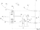
- FIG. 4 10 shows a drive system 100 according to an embodiment of the invention, which is essentially the drive system 100 of FIG Figure 2 corresponds, but with the difference that the limited slip differential function is implemented by a brake system BR1 and BR2 with selective brake intervention.
- variable limited slip differential function can expediently be given for both forward and reverse travel within the scope of the invention.
- Figure 5 shows a flow divider WV, preferably with a freewheel function, according to an embodiment of the invention.
- the representation is greatly simplified.
- the flow direction is from total flow to partial flow FI and FII.
- the flow divider WV is designed in the form of a proportional valve, with in particular electro-proportional amplification of a restoring force on the pressure compensator, in particular the adjusting element.
- each is a static spring that acts on the adjusting element with the same force.
- the freewheel function is preferably in this embodiment by a 3/2 way valve and z. B. realized two downstream check valves.
- Figure 6 shows a flow divider WV, preferably with a freewheel function, according to another embodiment of the invention.
- the flow divider WV is designed in the form of a proportional valve, in particular with electro-proportional hydraulic pressurization of the adjusting element.
- additional proportional valves V1 and V2 are used, which do not act on springs of the adjusting element, but rather on pressures in the hydraulic fluid volume flows FI and FII, which in turn act on the adjusting element.
- Figure 7 shows a flow divider according to the prior art, by means of which a limited slip differential function for traction compensation with forced synchronization of two wheels can be implemented during cornering.
- Throttles in the flow divider each have the same cross-section and the spring forces acting on the actuating piston from outside are of the same size. Under these conditions, the flow divider tries to ensure that the pressure in partial flow I (hydraulic fluid volume flow) is equal to the pressure in partial flow II (hydraulic fluid volume flow). Accordingly, the pressure in the two partial flows serves as the control variable for the flow divider. It is further assumed that partial flow I supplies a wheel motor for a right wheel and partial flow II supplies a wheel motor for a left wheel. Now reduces z. If, for example, the resistance in partial flow I (wheel loses grip), the division of the hydraulic fluid flow (oil flow) changes in favor of partial flow I (path of least resistance).
- Partial stream II receives correspondingly less hydraulic fluid. Since the throttles in the flow divider are the same size, the pressure of partial flow I and II will drift apart. Due to the larger volume flow of partial flow I, the pressure is also lower here. This pressure delta now acts on the pressure compensator (the lower pressure above, the higher pressure below) and moves the actuating piston upwards (infinitesimally short travel possible). The more the adjusting piston comes into position II, the less the throttling effect from total flow to partial flow II; the pressure acting from outside thus detunes the pressure compensator. In other words, by moving the adjusting piston upwards in position I, an artificial resistance is introduced in partial flow I or this is reduced in partial flow II.
Landscapes
- Engineering & Computer Science (AREA)
- Chemical & Material Sciences (AREA)
- Combustion & Propulsion (AREA)
- Transportation (AREA)
- Mechanical Engineering (AREA)
- Control Of Fluid Gearings (AREA)
- Retarders (AREA)
- Arrangement And Driving Of Transmission Devices (AREA)
Applications Claiming Priority (1)
| Application Number | Priority Date | Filing Date | Title |
|---|---|---|---|
| DE102018124020.1A DE102018124020A1 (de) | 2018-09-28 | 2018-09-28 | Antriebssystem mit variabler Sperrdifferential-Funktion |
Publications (2)
| Publication Number | Publication Date |
|---|---|
| EP3628524A1 true EP3628524A1 (fr) | 2020-04-01 |
| EP3628524B1 EP3628524B1 (fr) | 2021-08-25 |
Family
ID=68066541
Family Applications (1)
| Application Number | Title | Priority Date | Filing Date |
|---|---|---|---|
| EP19198499.6A Active EP3628524B1 (fr) | 2018-09-28 | 2019-09-20 | Système d'entraînement à fonction différentielle bloquant variable |
Country Status (2)
| Country | Link |
|---|---|
| EP (1) | EP3628524B1 (fr) |
| DE (1) | DE102018124020A1 (fr) |
Cited By (1)
| Publication number | Priority date | Publication date | Assignee | Title |
|---|---|---|---|---|
| EP4417477A1 (fr) * | 2023-02-17 | 2024-08-21 | Volvo Truck Corporation | Système et procédé de gestion du patinage de roue dans un véhicule |
Families Citing this family (1)
| Publication number | Priority date | Publication date | Assignee | Title |
|---|---|---|---|---|
| US12583515B2 (en) | 2021-06-14 | 2026-03-24 | Schaeffler Technologies AG & Co. KG | Electrically operable axle drive train, method for operating an electrically operable axle drive train, computer program product and control unit |
Citations (4)
| Publication number | Priority date | Publication date | Assignee | Title |
|---|---|---|---|---|
| DE3635095A1 (de) * | 1985-10-24 | 1987-04-30 | Volkswagen Ag | Verfahren und einrichtung zur vortriebsregelung eines kraftfahrzeugs im sinne des verhinderns eines unerwuenschten durchdrehens der angetriebenen fahrzeugraeder |
| EP1886861A2 (fr) | 2006-08-11 | 2008-02-13 | MAN Nutzfahrzeuge Österreich AG | Différentiell pour MAN-Hydrodrive |
| EP2559581A2 (fr) | 2011-08-18 | 2013-02-20 | MAN Truck & Bus AG | Système d'entraînement pour un véhicule automobile équipé d'un système de freinage agissant comme un différentiel à blocage |
| EP2759438A2 (fr) * | 2013-01-25 | 2014-07-30 | MAN Truck & Bus AG | Mécanisme d'entraînement de véhicule doté d'un entraînement auxiliaire hydrostatique, véhicule avec un tel mécanisme d'entraînement et procédé d'opération pour un tel mécanisme d'entraînement |
Family Cites Families (3)
| Publication number | Priority date | Publication date | Assignee | Title |
|---|---|---|---|---|
| US8662212B2 (en) * | 2009-06-04 | 2014-03-04 | Thomas Towles Lawson, Jr. | Four wheel drive system |
| DE102010012418B4 (de) * | 2010-03-23 | 2012-08-30 | Schäffer Maschinenfabrik GmbH | Allradangetriebener Hoflader mit stufenlos verstellbarem Sperrdifferential |
| DE102017211756A1 (de) * | 2017-07-10 | 2019-01-10 | Jungheinrich Aktiengesellschaft | Intelligente Differentialanordnung |
-
2018
- 2018-09-28 DE DE102018124020.1A patent/DE102018124020A1/de not_active Withdrawn
-
2019
- 2019-09-20 EP EP19198499.6A patent/EP3628524B1/fr active Active
Patent Citations (4)
| Publication number | Priority date | Publication date | Assignee | Title |
|---|---|---|---|---|
| DE3635095A1 (de) * | 1985-10-24 | 1987-04-30 | Volkswagen Ag | Verfahren und einrichtung zur vortriebsregelung eines kraftfahrzeugs im sinne des verhinderns eines unerwuenschten durchdrehens der angetriebenen fahrzeugraeder |
| EP1886861A2 (fr) | 2006-08-11 | 2008-02-13 | MAN Nutzfahrzeuge Österreich AG | Différentiell pour MAN-Hydrodrive |
| EP2559581A2 (fr) | 2011-08-18 | 2013-02-20 | MAN Truck & Bus AG | Système d'entraînement pour un véhicule automobile équipé d'un système de freinage agissant comme un différentiel à blocage |
| EP2759438A2 (fr) * | 2013-01-25 | 2014-07-30 | MAN Truck & Bus AG | Mécanisme d'entraînement de véhicule doté d'un entraînement auxiliaire hydrostatique, véhicule avec un tel mécanisme d'entraînement et procédé d'opération pour un tel mécanisme d'entraînement |
Cited By (2)
| Publication number | Priority date | Publication date | Assignee | Title |
|---|---|---|---|---|
| EP4417477A1 (fr) * | 2023-02-17 | 2024-08-21 | Volvo Truck Corporation | Système et procédé de gestion du patinage de roue dans un véhicule |
| US12454268B2 (en) | 2023-02-17 | 2025-10-28 | Volvo Truck Corporation | Handling wheel slip in a vehicle |
Also Published As
| Publication number | Publication date |
|---|---|
| EP3628524B1 (fr) | 2021-08-25 |
| DE102018124020A1 (de) | 2020-04-02 |
Similar Documents
| Publication | Publication Date | Title |
|---|---|---|
| EP0954460B1 (fr) | Procede et dispositif pour detecter la tendance au basculement d'un vehicule | |
| EP0553670B1 (fr) | Dispositif d'entraînement pour la commande et la répartition de la force motrice d'un véhicule | |
| DE4117897C2 (de) | System zur Erzeugung von Signalen zur Steuerung oder Regelung eines in seinen Bewegungsabläufen steuerbaren oder regelbaren Fahrwerkes | |
| DE3930445C2 (fr) | ||
| EP0920389B1 (fr) | Procede et dispositif pour le reglage de grandeurs representatives du mouvement d'un vehicule | |
| DE10348738B4 (de) | Steuerungssystem für ein Kraftfahrzeug und Verfahren zum Steuern eines Kraftfahrzeugs | |
| DE4404098C2 (de) | Fahrzeugregeleinrichtung | |
| DE3532222C2 (fr) | ||
| DE3705520C2 (de) | Regelungseinrichtung zur Beeinflussung der Radaufstandskräfte eines Fahrzeugs | |
| EP1417108B1 (fr) | Procede pour influer sur la tenue au roulis d'automobiles | |
| DE19615311B4 (de) | Verfahren und Vorrichtung zur Regelung einer die Fahrzeugbewegung repräsentierenden Bewegungsgröße | |
| DE69908784T2 (de) | Fahrzeugaufhängungen | |
| EP1030798A1 (fr) | Procede et dispositif pour stabiliser un vehicule en cas de tendance au basculement | |
| EP0348634A2 (fr) | Dispositif de contrôle antiroulis pour un véhicule | |
| EP0954461A1 (fr) | Procede et dispositif pour detecter la tendance au basculement d'un vehicule | |
| DE102013011883A1 (de) | Verfahren zum Betreiben der Lenkung eines Kranftfahrzeugs | |
| EP0803427B1 (fr) | Direction pour véhicule | |
| EP2759438B1 (fr) | Mécanisme d'entraînement de véhicule doté d'un entraînement auxiliaire hydrostatique, véhicule avec un tel mécanisme d'entraînement et procédé d'opération pour un tel mécanisme d'entraînement | |
| DE112018006928T5 (de) | Lenksteuervorrichtung und Lenkvorrichtung | |
| EP1483129A1 (fr) | Dispositif pour fournir des parametres | |
| EP0295396A2 (fr) | Système de freinage pour un véhicule dirigeable, à 2 ou plusieurs essieux, avec entraînement au moins sur les roues arrière | |
| DE3437436A1 (de) | Anordnung zur steuerung der kraftuebertragung eines vierradangetriebenen fahrzeuges | |
| DE69014620T2 (de) | Steuersystem für die aufhängung eines landfahrzeugs. | |
| DE4010277C2 (de) | Vorrichtung zur Regelung einer hydraulischen Aufhängung | |
| DE112022000824T5 (de) | Schlupfzustandsdetektionseinrichtung und Federungssteuerungseinrichtung |
Legal Events
| Date | Code | Title | Description |
|---|---|---|---|
| PUAI | Public reference made under article 153(3) epc to a published international application that has entered the european phase |
Free format text: ORIGINAL CODE: 0009012 |
|
| STAA | Information on the status of an ep patent application or granted ep patent |
Free format text: STATUS: THE APPLICATION HAS BEEN PUBLISHED |
|
| AK | Designated contracting states |
Kind code of ref document: A1 Designated state(s): AL AT BE BG CH CY CZ DE DK EE ES FI FR GB GR HR HU IE IS IT LI LT LU LV MC MK MT NL NO PL PT RO RS SE SI SK SM TR |
|
| AX | Request for extension of the european patent |
Extension state: BA ME |
|
| STAA | Information on the status of an ep patent application or granted ep patent |
Free format text: STATUS: REQUEST FOR EXAMINATION WAS MADE |
|
| 17P | Request for examination filed |
Effective date: 20200918 |
|
| RBV | Designated contracting states (corrected) |
Designated state(s): AL AT BE BG CH CY CZ DE DK EE ES FI FR GB GR HR HU IE IS IT LI LT LU LV MC MK MT NL NO PL PT RO RS SE SI SK SM TR |
|
| RIC1 | Information provided on ipc code assigned before grant |
Ipc: B60K 17/354 20060101AFI20210216BHEP Ipc: B60K 17/356 20060101ALI20210216BHEP |
|
| GRAP | Despatch of communication of intention to grant a patent |
Free format text: ORIGINAL CODE: EPIDOSNIGR1 |
|
| STAA | Information on the status of an ep patent application or granted ep patent |
Free format text: STATUS: GRANT OF PATENT IS INTENDED |
|
| INTG | Intention to grant announced |
Effective date: 20210409 |
|
| GRAS | Grant fee paid |
Free format text: ORIGINAL CODE: EPIDOSNIGR3 |
|
| GRAA | (expected) grant |
Free format text: ORIGINAL CODE: 0009210 |
|
| STAA | Information on the status of an ep patent application or granted ep patent |
Free format text: STATUS: THE PATENT HAS BEEN GRANTED |
|
| AK | Designated contracting states |
Kind code of ref document: B1 Designated state(s): AL AT BE BG CH CY CZ DE DK EE ES FI FR GB GR HR HU IE IS IT LI LT LU LV MC MK MT NL NO PL PT RO RS SE SI SK SM TR |
|
| REG | Reference to a national code |
Ref country code: CH Ref legal event code: EP |
|
| REG | Reference to a national code |
Ref country code: DE Ref legal event code: R096 Ref document number: 502019002123 Country of ref document: DE |
|
| REG | Reference to a national code |
Ref country code: IE Ref legal event code: FG4D Free format text: LANGUAGE OF EP DOCUMENT: GERMAN Ref country code: AT Ref legal event code: REF Ref document number: 1423449 Country of ref document: AT Kind code of ref document: T Effective date: 20210915 |
|
| REG | Reference to a national code |
Ref country code: SE Ref legal event code: TRGR |
|
| REG | Reference to a national code |
Ref country code: NL Ref legal event code: FP |
|
| REG | Reference to a national code |
Ref country code: LT Ref legal event code: MG9D |
|
| PG25 | Lapsed in a contracting state [announced via postgrant information from national office to epo] |
Ref country code: ES Free format text: LAPSE BECAUSE OF FAILURE TO SUBMIT A TRANSLATION OF THE DESCRIPTION OR TO PAY THE FEE WITHIN THE PRESCRIBED TIME-LIMIT Effective date: 20210825 Ref country code: FI Free format text: LAPSE BECAUSE OF FAILURE TO SUBMIT A TRANSLATION OF THE DESCRIPTION OR TO PAY THE FEE WITHIN THE PRESCRIBED TIME-LIMIT Effective date: 20210825 Ref country code: RS Free format text: LAPSE BECAUSE OF FAILURE TO SUBMIT A TRANSLATION OF THE DESCRIPTION OR TO PAY THE FEE WITHIN THE PRESCRIBED TIME-LIMIT Effective date: 20210825 Ref country code: BG Free format text: LAPSE BECAUSE OF FAILURE TO SUBMIT A TRANSLATION OF THE DESCRIPTION OR TO PAY THE FEE WITHIN THE PRESCRIBED TIME-LIMIT Effective date: 20211125 Ref country code: LT Free format text: LAPSE BECAUSE OF FAILURE TO SUBMIT A TRANSLATION OF THE DESCRIPTION OR TO PAY THE FEE WITHIN THE PRESCRIBED TIME-LIMIT Effective date: 20210825 Ref country code: PT Free format text: LAPSE BECAUSE OF FAILURE TO SUBMIT A TRANSLATION OF THE DESCRIPTION OR TO PAY THE FEE WITHIN THE PRESCRIBED TIME-LIMIT Effective date: 20211227 Ref country code: NO Free format text: LAPSE BECAUSE OF FAILURE TO SUBMIT A TRANSLATION OF THE DESCRIPTION OR TO PAY THE FEE WITHIN THE PRESCRIBED TIME-LIMIT Effective date: 20211125 Ref country code: HR Free format text: LAPSE BECAUSE OF FAILURE TO SUBMIT A TRANSLATION OF THE DESCRIPTION OR TO PAY THE FEE WITHIN THE PRESCRIBED TIME-LIMIT Effective date: 20210825 |
|
| PG25 | Lapsed in a contracting state [announced via postgrant information from national office to epo] |
Ref country code: PL Free format text: LAPSE BECAUSE OF FAILURE TO SUBMIT A TRANSLATION OF THE DESCRIPTION OR TO PAY THE FEE WITHIN THE PRESCRIBED TIME-LIMIT Effective date: 20210825 Ref country code: LV Free format text: LAPSE BECAUSE OF FAILURE TO SUBMIT A TRANSLATION OF THE DESCRIPTION OR TO PAY THE FEE WITHIN THE PRESCRIBED TIME-LIMIT Effective date: 20210825 Ref country code: GR Free format text: LAPSE BECAUSE OF FAILURE TO SUBMIT A TRANSLATION OF THE DESCRIPTION OR TO PAY THE FEE WITHIN THE PRESCRIBED TIME-LIMIT Effective date: 20211126 |
|
| PG25 | Lapsed in a contracting state [announced via postgrant information from national office to epo] |
Ref country code: DK Free format text: LAPSE BECAUSE OF FAILURE TO SUBMIT A TRANSLATION OF THE DESCRIPTION OR TO PAY THE FEE WITHIN THE PRESCRIBED TIME-LIMIT Effective date: 20210825 |
|
| REG | Reference to a national code |
Ref country code: BE Ref legal event code: MM Effective date: 20210930 |
|
| REG | Reference to a national code |
Ref country code: DE Ref legal event code: R097 Ref document number: 502019002123 Country of ref document: DE |
|
| PG25 | Lapsed in a contracting state [announced via postgrant information from national office to epo] |
Ref country code: SM Free format text: LAPSE BECAUSE OF FAILURE TO SUBMIT A TRANSLATION OF THE DESCRIPTION OR TO PAY THE FEE WITHIN THE PRESCRIBED TIME-LIMIT Effective date: 20210825 Ref country code: SK Free format text: LAPSE BECAUSE OF FAILURE TO SUBMIT A TRANSLATION OF THE DESCRIPTION OR TO PAY THE FEE WITHIN THE PRESCRIBED TIME-LIMIT Effective date: 20210825 Ref country code: RO Free format text: LAPSE BECAUSE OF FAILURE TO SUBMIT A TRANSLATION OF THE DESCRIPTION OR TO PAY THE FEE WITHIN THE PRESCRIBED TIME-LIMIT Effective date: 20210825 Ref country code: MC Free format text: LAPSE BECAUSE OF FAILURE TO SUBMIT A TRANSLATION OF THE DESCRIPTION OR TO PAY THE FEE WITHIN THE PRESCRIBED TIME-LIMIT Effective date: 20210825 Ref country code: EE Free format text: LAPSE BECAUSE OF FAILURE TO SUBMIT A TRANSLATION OF THE DESCRIPTION OR TO PAY THE FEE WITHIN THE PRESCRIBED TIME-LIMIT Effective date: 20210825 Ref country code: CZ Free format text: LAPSE BECAUSE OF FAILURE TO SUBMIT A TRANSLATION OF THE DESCRIPTION OR TO PAY THE FEE WITHIN THE PRESCRIBED TIME-LIMIT Effective date: 20210825 Ref country code: AL Free format text: LAPSE BECAUSE OF FAILURE TO SUBMIT A TRANSLATION OF THE DESCRIPTION OR TO PAY THE FEE WITHIN THE PRESCRIBED TIME-LIMIT Effective date: 20210825 |
|
| PLBE | No opposition filed within time limit |
Free format text: ORIGINAL CODE: 0009261 |
|
| STAA | Information on the status of an ep patent application or granted ep patent |
Free format text: STATUS: NO OPPOSITION FILED WITHIN TIME LIMIT |
|
| PG25 | Lapsed in a contracting state [announced via postgrant information from national office to epo] |
Ref country code: LU Free format text: LAPSE BECAUSE OF NON-PAYMENT OF DUE FEES Effective date: 20210920 Ref country code: IE Free format text: LAPSE BECAUSE OF NON-PAYMENT OF DUE FEES Effective date: 20210920 Ref country code: BE Free format text: LAPSE BECAUSE OF NON-PAYMENT OF DUE FEES Effective date: 20210930 |
|
| 26N | No opposition filed |
Effective date: 20220527 |
|
| PG25 | Lapsed in a contracting state [announced via postgrant information from national office to epo] |
Ref country code: SI Free format text: LAPSE BECAUSE OF FAILURE TO SUBMIT A TRANSLATION OF THE DESCRIPTION OR TO PAY THE FEE WITHIN THE PRESCRIBED TIME-LIMIT Effective date: 20210825 |
|
| REG | Reference to a national code |
Ref country code: CH Ref legal event code: PL |
|
| PG25 | Lapsed in a contracting state [announced via postgrant information from national office to epo] |
Ref country code: CY Free format text: LAPSE BECAUSE OF FAILURE TO SUBMIT A TRANSLATION OF THE DESCRIPTION OR TO PAY THE FEE WITHIN THE PRESCRIBED TIME-LIMIT Effective date: 20210825 |
|
| PG25 | Lapsed in a contracting state [announced via postgrant information from national office to epo] |
Ref country code: LI Free format text: LAPSE BECAUSE OF NON-PAYMENT OF DUE FEES Effective date: 20220930 Ref country code: HU Free format text: LAPSE BECAUSE OF FAILURE TO SUBMIT A TRANSLATION OF THE DESCRIPTION OR TO PAY THE FEE WITHIN THE PRESCRIBED TIME-LIMIT; INVALID AB INITIO Effective date: 20190920 Ref country code: CH Free format text: LAPSE BECAUSE OF NON-PAYMENT OF DUE FEES Effective date: 20220930 |
|
| PG25 | Lapsed in a contracting state [announced via postgrant information from national office to epo] |
Ref country code: MK Free format text: LAPSE BECAUSE OF FAILURE TO SUBMIT A TRANSLATION OF THE DESCRIPTION OR TO PAY THE FEE WITHIN THE PRESCRIBED TIME-LIMIT Effective date: 20210825 |
|
| GBPC | Gb: european patent ceased through non-payment of renewal fee |
Effective date: 20230920 |
|
| PG25 | Lapsed in a contracting state [announced via postgrant information from national office to epo] |
Ref country code: TR Free format text: LAPSE BECAUSE OF FAILURE TO SUBMIT A TRANSLATION OF THE DESCRIPTION OR TO PAY THE FEE WITHIN THE PRESCRIBED TIME-LIMIT Effective date: 20210825 |
|
| PG25 | Lapsed in a contracting state [announced via postgrant information from national office to epo] |
Ref country code: GB Free format text: LAPSE BECAUSE OF NON-PAYMENT OF DUE FEES Effective date: 20230920 |
|
| PG25 | Lapsed in a contracting state [announced via postgrant information from national office to epo] |
Ref country code: GB Free format text: LAPSE BECAUSE OF NON-PAYMENT OF DUE FEES Effective date: 20230920 |
|
| PG25 | Lapsed in a contracting state [announced via postgrant information from national office to epo] |
Ref country code: MT Free format text: LAPSE BECAUSE OF FAILURE TO SUBMIT A TRANSLATION OF THE DESCRIPTION OR TO PAY THE FEE WITHIN THE PRESCRIBED TIME-LIMIT Effective date: 20210825 |
|
| PGFP | Annual fee paid to national office [announced via postgrant information from national office to epo] |
Ref country code: DE Payment date: 20250926 Year of fee payment: 7 |
|
| PGFP | Annual fee paid to national office [announced via postgrant information from national office to epo] |
Ref country code: NL Payment date: 20250925 Year of fee payment: 7 Ref country code: IT Payment date: 20250922 Year of fee payment: 7 |
|
| PGFP | Annual fee paid to national office [announced via postgrant information from national office to epo] |
Ref country code: FR Payment date: 20250925 Year of fee payment: 7 |
|
| PGFP | Annual fee paid to national office [announced via postgrant information from national office to epo] |
Ref country code: SE Payment date: 20250924 Year of fee payment: 7 |
|
| REG | Reference to a national code |
Ref country code: AT Ref legal event code: MM01 Ref document number: 1423449 Country of ref document: AT Kind code of ref document: T Effective date: 20240920 |
|
| PG25 | Lapsed in a contracting state [announced via postgrant information from national office to epo] |
Ref country code: AT Free format text: LAPSE BECAUSE OF NON-PAYMENT OF DUE FEES Effective date: 20240920 |
|
| PGFP | Annual fee paid to national office [announced via postgrant information from national office to epo] |
Ref country code: AT Payment date: 20260410 Year of fee payment: 5 |