EP3629103B1 - Uhr, die ein mechanisches uhrwerk umfasst, dessen ganggenauigkeit durch eine elektronische vorrichtung reguliert wird - Google Patents
Uhr, die ein mechanisches uhrwerk umfasst, dessen ganggenauigkeit durch eine elektronische vorrichtung reguliert wird Download PDFInfo
- Publication number
- EP3629103B1 EP3629103B1 EP18197529.3A EP18197529A EP3629103B1 EP 3629103 B1 EP3629103 B1 EP 3629103B1 EP 18197529 A EP18197529 A EP 18197529A EP 3629103 B1 EP3629103 B1 EP 3629103B1
- Authority
- EP
- European Patent Office
- Prior art keywords
- frequency
- control
- control device
- timepiece according
- pulses
- Prior art date
- Legal status (The legal status is an assumption and is not a legal conclusion. Google has not performed a legal analysis and makes no representation as to the accuracy of the status listed.)
- Active
Links
Images


Classifications
-
- G—PHYSICS
- G04—HOROLOGY
- G04B—MECHANICALLY-DRIVEN CLOCKS OR WATCHES; MECHANICAL PARTS OF CLOCKS OR WATCHES IN GENERAL; TIME PIECES USING THE POSITION OF THE SUN, MOON OR STARS
- G04B17/00—Mechanisms for stabilising frequency
- G04B17/04—Oscillators acting by spring tension
- G04B17/06—Oscillators with hairsprings, e.g. balance
- G04B17/063—Balance construction
-
- G—PHYSICS
- G04—HOROLOGY
- G04C—ELECTROMECHANICAL CLOCKS OR WATCHES
- G04C3/00—Electromechanical clocks or watches independent of other time-pieces and in which the movement is maintained by electric means
- G04C3/04—Electromechanical clocks or watches independent of other time-pieces and in which the movement is maintained by electric means wherein movement is regulated by a balance
- G04C3/047—Electromechanical clocks or watches independent of other time-pieces and in which the movement is maintained by electric means wherein movement is regulated by a balance using other coupling means, e.g. electrostrictive, magnetostrictive
-
- G—PHYSICS
- G04—HOROLOGY
- G04B—MECHANICALLY-DRIVEN CLOCKS OR WATCHES; MECHANICAL PARTS OF CLOCKS OR WATCHES IN GENERAL; TIME PIECES USING THE POSITION OF THE SUN, MOON OR STARS
- G04B17/00—Mechanisms for stabilising frequency
- G04B17/04—Oscillators acting by spring tension
- G04B17/06—Oscillators with hairsprings, e.g. balance
- G04B17/066—Manufacture of the spiral spring
-
- G—PHYSICS
- G04—HOROLOGY
- G04B—MECHANICALLY-DRIVEN CLOCKS OR WATCHES; MECHANICAL PARTS OF CLOCKS OR WATCHES IN GENERAL; TIME PIECES USING THE POSITION OF THE SUN, MOON OR STARS
- G04B17/00—Mechanisms for stabilising frequency
- G04B17/20—Compensation of mechanisms for stabilising frequency
- G04B17/22—Compensation of mechanisms for stabilising frequency for the effect of variations of temperature
- G04B17/222—Compensation of mechanisms for stabilising frequency for the effect of variations of temperature with balances
-
- G—PHYSICS
- G04—HOROLOGY
- G04B—MECHANICALLY-DRIVEN CLOCKS OR WATCHES; MECHANICAL PARTS OF CLOCKS OR WATCHES IN GENERAL; TIME PIECES USING THE POSITION OF THE SUN, MOON OR STARS
- G04B17/00—Mechanisms for stabilising frequency
- G04B17/20—Compensation of mechanisms for stabilising frequency
- G04B17/22—Compensation of mechanisms for stabilising frequency for the effect of variations of temperature
- G04B17/227—Compensation of mechanisms for stabilising frequency for the effect of variations of temperature composition and manufacture of the material used
-
- G—PHYSICS
- G04—HOROLOGY
- G04C—ELECTROMECHANICAL CLOCKS OR WATCHES
- G04C3/00—Electromechanical clocks or watches independent of other time-pieces and in which the movement is maintained by electric means
- G04C3/04—Electromechanical clocks or watches independent of other time-pieces and in which the movement is maintained by electric means wherein movement is regulated by a balance
Definitions
- the present invention relates to a timepiece comprising a mechanical movement, provided with a mechanical oscillator which is formed by a balance wheel and a hairspring, and an electronic regulating device for regulating the frequency of the mechanical oscillator which controls the operation of the. mechanical movement.
- the electronic regulation device comprises an auxiliary oscillator of the electronic type which is generally more precise than the mechanical oscillator, in particular a quartz oscillator.
- the patent application US 2013/051191 relates to a timepiece comprising a sprung balance and an electronic circuit for regulating the frequency of oscillation of this sprung balance.
- the hairspring is made of a piezoelectric material or has two side layers of piezoelectric material on a silicon core, two outer side electrodes being arranged on the side surfaces of the hairspring. These two electrodes are connected to the electronic regulation circuit which comprises a plurality of switchable capacitors arranged in parallel and connected to the two electrodes of the hairspring.
- FIG. 1 Using the Figures 1 to 4 , a timepiece of the type described in the aforementioned American patent application will be described.
- Figure 1 only the mechanical resonator 2 of the mechanical movement of the timepiece, this resonator comprising a balance 4 oscillating around a geometric axis 6 and a hairspring 8 whose end curve 10 conventionally passes through a stud 12 integral with a balance bridge (not shown) of the mechanical movement.
- the Figure 2 schematically shows a portion of the hairspring 8.
- This hairspring is formed by a central body 14 in silicon, two side layers 16, 18 in piezoelectric material, in particular in aluminum nitride (AIN), and two external metal electrodes 20, 22.
- the two electrodes are connected by conductive wires 26, 28 (schematic representation) to an electronic regulation circuit 24.
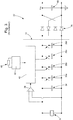
- the Figure 3 (which reproduces the figure 1 of the previous document considered with some additional information from figures 2 and 7 ) shows the general arrangement of the regulation device 32 which is incorporated in the timepiece in question and in particular the electronic regulation circuit 24.
- This circuit 24 comprises a first capacitor 34 connected to the two electrodes of the piezoelectric balance spring and a plurality switchable capacitors 36a to 36d which are arranged in parallel with the first capacitor, so as to form a variable capacitor Cv in order to be able to vary the value of the capacitance connected to the electrodes of the balance spring and thus vary, according to the teaching of the document, the rigidity of the hairspring.
- the circuit 24 further comprises a comparator 38 whose two inputs are connected respectively to the two electrodes of the balance spring 8, this comparator being provided to supply a logic signal making it possible to determine, thanks to the successive changes of the logic state of this logic signal by zero of the voltage induced between the two electrodes of the balance spring.
- the logic signal is supplied to a logic circuit 40 which also receives a reference signal from a clock circuit 42 associated with a crystal resonator 44. Based on a comparison between the reference signal and the supplied logic signal by comparator 38, logic circuit 40 controls the switches of switchable capacitors 36a to 36d.
- a full-wave rectifier circuit 46 conventionally formed of a bridge with four diodes, which supplies a direct voltage V DC and charges a storage capacitor 48.
- This supplied electrical energy. by the piezoelectric balance spring enables the device 32 to be powered.
- We therefore have an autonomous electrical system because it is self-powered in the sense that the electrical energy comes from the mechanical energy supplied to the mechanical resonator 2, including the piezoelectric balance spring 8, when the resonator mechanical oscillates, forms an electromechanical transducer (an electric current generator).
- the electronic regulation circuit 24 can only reduce the oscillation frequency of the mechanical resonator 2 by increasing the value of the variable capacitance Cv.
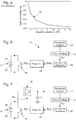
- This observation is confirmed by the graph of the Figure 4 which shows the curve 50 giving the operating deviation as a function of the value of the variable capacitance Cv. It is in fact observed that the operating deviation obtained is always less than zero and increases in absolute value when the value of the variable capacitance increases.
- the regulation system requests that the natural frequency of the mechanical oscillator (frequency in the absence of regulation) be greater than the nominal frequency (reference frequency) of this mechanical oscillator.
- the document CH 705 679 A2 describes a very similar control device compared to that described in US2013 / 051191 .
- the DC voltage is varied using a network of capacitors and / or resistors.
- the document EP 1 164 441 A1 discloses a mechanical timepiece having a sprung balance oscillator and a Swiss lever escapement.
- the frequency of the mechanical oscillator is first measured by counting, over a time span of one hour, the number of strikes of the anchor on piezoelectric pins, then it is regulated by an electronic regulating device.
- This regulation circuit acts on a piezoelectric element which varies the length of the hairspring by moving the eyebolt.
- the document EP 2 908 187 A1 describes a balance-spring oscillator with a piezoelectric balance-spring.
- a circuit connected to the hairspring electrodes is used to maintain the oscillator and to stabilize its oscillation frequency at the value of its natural frequency.
- the object of the present invention is to provide a timepiece, provided with a mechanical resonator comprising a balance spring formed at least partially from a piezoelectric material and an electronic regulation system, associated with the piezoelectric balance spring, which does not have the drawbacks of the timepiece of the prior art described above, in particular which can be associated with a mechanical movement the rate of which is initially adjusted optimally, that is to say to the best of its ability.
- the objective of the invention is to provide an electronic regulation system which is, thanks to the use of a piezoelectric balance spring, discrete and autonomous and which is truly complementary to the mechanical movement by making it possible to increase its precision without degrading by elsewhere an optimal initial adjustment of this mechanical movement.
- the object of the invention is a timepiece comprising a regulating device arranged to be able to regulate the average frequency of a mechanical oscillator, formed by a balance wheel and a hairspring, which rates the rate of the piece.
- this regulation device comprising an auxiliary time base, formed by an auxiliary electronic oscillator, which supplies a reference frequency signal for regulation.
- the hairspring is formed at least partially by a piezoelectric material and by at least two electrodes arranged so as to present between them a voltage induced by the piezoelectric material undergoing mechanical stress and electrically connected to the regulation device which is arranged to be able to vary the impedance of the system regulation formed by the piezoelectric material, the at least two electrodes and the regulation device.
- the regulation device is arranged so as to be able to momentarily vary the electrical resistance generated by this control device.
- regulation between the at least two electrodes in order to be able to generate, at least at times, regulation pulses which are distinct and each have a certain duration T P , each regulation pulse consisting of a momentary decrease in said electrical resistance relative to a nominal electrical resistance which is generated by the regulation device between the two electrodes apart from the separate regulation pulses.
- the regulation device is arranged to determine by means of the reference time base the start of each of the regulation pulses, so as to satisfy the aforementioned mathematical relationship between the time distance and the regulation period, and thereby to determine the frequency. regulation.
- said moments are contiguous and together form a continuous time range.
- the regulation device is arranged to apply the regulation pulses during the continuous time range in such a way that any two successive regulation pulses occurring in this continuous time range have, between their beginnings, the time distance D T with the regulation period Treg equal to one reference period T0c, which is the inverse of the reference frequency F0c, so as to be able to continuously synchronize, after a possible initial transient phase, the frequency of the mechanical oscillator on a reference frequency F0c during the continuous time range.
- the number N, respectively M is constant and predefined for the continuous time range.
- the timepiece further comprises a device for measuring a time drift in the operation of the mechanical oscillator relative to its setpoint frequency F0c, and the regulating device is arranged to select , before each of said moments, for the regulation period Treg, depending on whether at least a certain positive or negative time drift is detected, respectively a first correction period Tcor1 which is greater than a setpoint period T0c, equal to the reverse of the setpoint frequency, or a second correction period Tcor2 which is less than the setpoint period.
- the number N, respectively M is constant during each of said moments and it is either predetermined or determined before the following moment considered.
- the characteristics of the timepiece according to the invention it is possible to correct both an advance and a delay in the natural course of a mechanical movement by acting by regulating pulses, each having a limited duration, which vary the resistance between the at least two electrodes of the hairspring which is formed at least partially of a piezoelectric material.
- the separate regulation pulses are applied without interruption and the times of their triggering are determined so that the frequency of the mechanical oscillator is constantly synchronized with a setpoint frequency, so that none time drift occurs after an initial phase to obtain the desired synchronization.
- This first embodiment is very advantageous by virtue of the simplicity of its electronic circuit.
- the regulation system generates an induced voltage between the two electrodes of the hairspring, which makes it possible to easily count the alternations or periods of the mechanical oscillator and thus be able to detect a temporal drift in the progress of the timepiece.
- the timepiece according to the invention comprises, like the timepiece of the prior art described above, a mechanical watch movement provided with a mechanical oscillator, formed by a balance and a piezoelectric balance-spring, for example as shown. to the Figures 1 and 2 , and arranged to clock the rate of the watch movement, this mechanical oscillator having a predefined reference frequency F0c.
- the hairspring is formed at least partially by a piezoelectric material and it comprises two electrodes 20, 22 arranged so as to be able to present between them a voltage induced by the piezoelectric material when the latter is placed under mechanical stress during an oscillation of the piezoelectric material. mechanical oscillator.
- the timepiece further comprises a regulating device arranged in order to be able to regulate the average frequency of the mechanical oscillator and comprising an auxiliary time base, formed by an auxiliary electronic oscillator and supplying a reference frequency signal.
- the two electrodes of the hairspring are electrically connected to the regulation device which is arranged to be able to vary the impedance of the regulation system which is formed by the piezoelectric material, the two electrodes and the regulation device.
- the regulation device is arranged so as to be able to momentarily vary the electrical resistance generated by this regulation device between the two electrodes of the balance spring, in order to be able to generate, at least at times, regulation pulses which are distinct and each have a certain duration T P , each regulation pulse consisting of a momentary decrease in the electrical resistance of the regulation system, namely the aforementioned electrical resistance relative to a nominal electrical resistance which is generated by the regulation device between the two electrodes outside separate regulation pulses.
- the regulation device is arranged to determine by means of the reference time base the start of each of said regulation pulses, so as to satisfy the aforementioned mathematical relation between the temporal distance D T and the regulation period Treg, and thus to determine the regulation frequency.
- F D (M) 2.Freg / (2M - 1) for the advantageous variant mentioned above.
- the electronic circuit which forms the entire regulator device 52, is very simple.
- a quartz resonator 44 is excited by a clock circuit 42, the latter supplying a reference signal S Ref either at the frequency of the quartz F Q , preferably at a frequency adjusted to 32'768 Hz, or at a fraction of this frequency F Q , for example F Q / 4 and preferably at a fraction of the frequency adjusted in particular by means of an inhibition circuit known to the person skilled in the art.
- the reference signal S Ref is supplied to a frequency divider 64 which outputs a control signal S com to a timer 58 which, in response to the control signal, supplies a short-circuit signal Scc to a switch 60 arranged between the two electrodes 20, 22 of the piezoelectric balance spring 8 (shown schematically on Figure 6 ) at the frequency imposed by the control signal.
- This process takes place without interruption over a continuous period of time which lasts as long as the regulating device is active, that is to say as long as it is supplied with electricity.
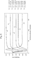
- the piezoelectric balance spring 8 is formed at least partially by a piezoelectric material and by at least two electrodes 20, 22 (see Figures2 and 10 ) which are arranged so as to be able to present between them an induced voltage U (t) by the piezoelectric material when the latter is placed under mechanical stress during an oscillation of the mechanical oscillator (see Figure 9 ).
- the numbers N and M are constant and predefined po ur the continuous time range during which the short-circuit pulses which define the regulation pulses are applied.
- the timer 58 at each pulse of the control signal, closes the switch 60 (switch on and therefore on) during a time interval T R , so that the short-circuit pulses each have a duration T R , which is preferably planned to be less than a quarter of the setpoint period T0c.
- the duration of the regulation pulses is less than or substantially equal to one tenth of the reference period T0c.
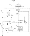
- FIG. 7 To the Figure 7 is shown the electronic diagram of a regulation device, identical to that described above, which is associated with a supply circuit 66, formed of a rectifier 68 of an induced voltage U (t) between the two electrodes 20, 22 of the hairspring 8 when the mechanical resonator oscillates and arranged to supply the regulation device 62, the rectified voltage being stored in a storage capacity C AL , so that the regulation device with the power supply circuit form a unit autonomous.
- this autonomous unit is supported by the balance 4 (see Figure 1 ) to which it is attached.
- the timepiece comprises a regulation device 62 formed by an electronic regulation circuit 62a and an auxiliary time base which comprises an auxiliary oscillator and which supplies a reference signal S Ref to the electronic regulation circuit.
- This time base comprises for example a quartz resonator 44 and a clock circuit 42 which supplies the reference signal S Ref , already described in the context of the first main embodiment, to a divider having at least two stages DIV1 and DIV2, this divider being included in the circuit 62a.
- the piezoelectric hairspring 8 is similar to that described in the first main embodiment and its two electrodes 20, 22 are electrically connected to the electronic regulation circuit 62a.
- the electronic regulation circuit comprises a device for measuring a possible temporal drift in the operation of the watch movement relative to a reference frequency for the mechanical oscillator which is determined by the auxiliary time base 42,44.
- the measuring device is formed by a hysteresis comparator 54, the two inputs of which are connected to the two electrodes 20, 22 of the piezoelectric balance spring 8. It will be noted that in the example given, the electrode 20 is electrically connected to an input of the comparator 54 via the ground of the regulation device.
- the hysteresis comparator supplies a digital 'Comp' signal (see Figure 9 ) whose logic state changes just after each passage of the mechanical oscillator through its neutral position (angular position ⁇ (t) equal to zero) and therefore after each passage through zero of the mechanical resonator forming this mechanical oscillator.
- the induced voltage U (t) generated by the piezoelectric balance spring is zero when the mechanical resonator passes through its neutral position (angular position 'zero'), while it is maximum, for a given load applied between the two electrodes, when the mechanical resonator is in one or the other of its two extreme positions (defining the amplitude of the mechanical oscillator respectively on both sides of the neutral position), as shown in Figure 9 .
- the 'Comp' signal is supplied to a first 'Up' input of a bidirectional counter CB forming the measuring device.
- the bidirectional counter is thus incremented by one unit for each period of oscillation of the mechanical oscillator (in particular on each rising edge of the signal). It therefore continuously receives a measurement of the instantaneous oscillation frequency of the mechanical oscillator.
- the bidirectional counter receives at its second 'Down' input a clock signal S hor supplied by the frequency divider DIV1 & DIV2, this clock signal corresponding to a reference frequency F0c for the mechanical oscillator which is determined by l auxiliary oscillator of the auxiliary time base.
- the bidirectional counter supplies the logic control circuit 56 with a signal S DT corresponding to an error accumulated over time between the oscillation frequency of the mechanical oscillator and the reference frequency, this cumulative error defining the time drift of the mechanical oscillator relative to the auxiliary oscillator.
- the regulation device 62 comprises a switch 60 formed by a transistor and arranged between the two electrodes 20, 22 of the hairspring 8, this switch being controlled by the logic control circuit 56. which is arranged to be able to temporarily close, via a timer 58, this switch so as to make it on / conductive during the regulation pulses, which then define short-circuit pulses.
- the control circuit selectively supplies a control signal S com to the timer 58 which, in response to this control signal, controls the momentary closing of the transistor 60 by applying a signal Scc to it.
- the control circuit determines the instant of the start of each short-circuit pulse by triggering or resetting the timer ('Timer') which makes transistor 60 directly on / conductive (switch closed), the timer determining the duration T R of each short-circuit pulse.
- the timer opens the switch again so that the transistor 60 is no longer conducting, that is to say that it becomes non-conductive again.
- the regulation pulses each have a duration less than a quarter of the reference period T0c which is equal to the inverse of the reference frequency for the mechanical oscillator.
- the duration of the regulation pulses is less than or substantially equal to one tenth of a set period.
- the electronic circuit 62a further comprises a supply circuit 66 for the regulation device, which has already been described above.
- the regulation method according to the second main embodiment, implemented by the regulation device 62 and implemented in the control logic circuit 56, is explained below.
- the control logic circuit is designed to be able to determine whether a time drift measured by the measuring device corresponds to at least a certain advance (CB> N1) or to at least a certain delay (CB ⁇ - N2), N1 and N2 being positive integers.
- the number N is preferably expected to be constant during each correction moment and it is either predetermined or determined before the next considered correction moment.
- the whole number N is made smaller in an initial phase than in a final phase of each of the correction moments, so as to best reduce the initial transient phase.
- the number M is expected to be constant during each correction moment and it is either predetermined or determined before the next correction moment considered.
- a first regulation pulse from among the plurality of regulation pulses provided for the correction moment. considered, relative to the angular position of the mechanical oscillator.
- the signal “Comp” is also supplied to the logic control circuit 56.
- the first regulation pulse is triggered by a rising edge or a falling edge of the signal “Comp”.
- This hairspring 70 shown in cross section, comprises a central body 72 in silicon, a silicon oxide layer 74 deposited on the surface of the central body so as to thermally compensate the hairspring, a conductive layer 76 deposited on the oxide layer. silicon, and a piezoelectric material deposited in the form of a piezoelectric layer 78 on the conductive layer 76.
- Two electrodes 20a and 22a are arranged on the piezoelectric layer 78 respectively on the two lateral sides of the hairspring (the two electrodes being able to partially cover the lower and upper sides of the hairspring without however joining).
- the first part 80a and the second part 80b of the piezoelectric layer extending respectively on the two lateral sides of the central body 72 have, by their growth from the conductive layer 76, respective crystallographic structures which are symmetrical with respect to a plane median 84 parallel to these two lateral sides.
- the piezoelectric layer has two same respective piezoelectric axes 82a, 82b which are perpendicular to the piezoelectric layer and in opposite directions. We therefore have an inversion of the sign of the voltage induced between the internal electrode and each of the two external side electrodes for the same mechanical stress.
- the hairspring contracts or expands from its rest position, there is a reversal of the mechanical stress between the first and second parts 80a and 80b, that is to say that one of these parts is subjected compression while the other of these parts is under tension, and vice versa.
- the voltages induced in the first and second parts have, along an axis perpendicular to the two lateral sides, the same polarity so that the conductive layer 76 can form one and the same internal electrode which extends on the two lateral sides of the central body 72, this internal electrode not having its own electrical connection with the regulation device.
- the piezoelectric layer consists of an aluminum nitride crystal formed by a growth of this crystal from the conductive layer 76 (internal electrode) and perpendicularly thereto.
Landscapes
- Physics & Mathematics (AREA)
- General Physics & Mathematics (AREA)
- Engineering & Computer Science (AREA)
- Metallurgy (AREA)
- Manufacturing & Machinery (AREA)
- Electric Clocks (AREA)
- Oscillators With Electromechanical Resonators (AREA)
- General Electrical Machinery Utilizing Piezoelectricity, Electrostriction Or Magnetostriction (AREA)
Claims (20)
- Teil für die Uhrmacherei, umfassend ein mechanisches Werk, das mit einem mechanischen Oszillator ausgestattet ist, der von einer Unruh (4) und einer Spirale (8; 70) gebildet wird, wobei dieser mechanische Oszillator eine vordefinierte Sollfrequenz F0c aufweist und angeordnet ist, um den Gang des Teils für die Uhrmacherei zu takten, wobei dieses Teil für die Uhrmacherei weiter eine Regulierungsvorrichtung (52, 62) umfasst, die angeordnet ist, um die mittlere Frequenz des mechanischen Oszillators regulieren zu können, und die eine Hilfszeitbasis (42, 44) umfasst, die von einem elektronischen Hilfsoszillator gebildet wird und ein Referenzsignal (SRef) bereitstellt, wobei die Spirale wenigstens teilweise von einem piezoelektrischen Werkstoff und von wenigstens zwei Elektroden (20, 22; 20a, 22a) gebildet wird, die angeordnet sind, um dazwischen eine durch den piezoelektrischen Werkstoff induzierte Spannung U(t) aufweisen zu können, wenn dieser Letztere bei einer Schwingung des mechanischen Oszillators mechanisch beansprucht wird, wobei die zwei Elektroden elektrisch mit der Regulierungsvorrichtung verbunden sind, die angeordnet ist, um die Impedanz des Regulierungssystems variieren zu können, das von dem piezoelektrischen Werkstoff, den wenigstens zwei Elektroden und der Regulierungsvorrichtung gebildet wird; dadurch gekennzeichnet, dass die Regulierungsvorrichtung (62) angeordnet ist, um den elektrischen Widerstand, der von dieser Regulierungsvorrichtung zwischen den zwei Elektroden erzeugt wird, momentan variieren zu können, um wenigstens momentweise Regulierungsimpulse erzeugen zu können, die verschieden sind und jeweils eine gewisse Dauer (TP) aufweisen, wobei jeder Regulierungsimpuls in einer momentanen Verringerung des elektrischen Widerstands in Bezug auf einen elektrischen Nennwiderstand besteht, der von der Regulierungsvorrichtung zwischen den zwei Elektroden außerhalb der verschiedenen Regulierungsimpulse erzeugt wird, wobei die Regulierungsvorrichtung angeordnet ist, um eine Vielzahl der Regulierungsimpulse während jedes der Momente anwenden zu können, sodass irgendwelche zwei aufeinanderfolgenden Regulierungsimpulse unter jeder Vielzahl von Regulierungsimpulsen zwischen ihren Anfängen eine zeitliche Distanz DT aufweisen, die gleich ist einer Zahl N multipliziert mit der Hälfte einer Regulierungsperiode Treg, die für jeden der Momente bestimmt wird, das heißt eine mathematische Beziehung DT=N·Treg/2, wobei N eine positive ganze Zahl größer als null ist, wobei die Regulierungsperiode Treg und die Zahl N so ausgewählt werden, dass eine Synchronisation des mechanischen Oszillators auf eine Regulierungsfrequenz Freg=1/Treg während jedes der Momente ermöglicht wird, wobei die Regulierungsvorrichtung angeordnet ist, um mittels der Referenzzeitbasis den Anfang jedes der Regulierungsimpulse zu bestimmen, um die mathematische Beziehung zwischen der zeitlichen Distanz und der Regulierungsperiode zu erfüllen und um somit die Regulierungsfrequenz zu bestimmen.
- Teil für die Uhrmacherei nach Anspruch 1, dadurch gekennzeichnet, dass es weiter eine Messvorrichtung (54, CB) für eine zeitliche Abweichung im Betrieb des mechanischen Oszillators in Bezug auf seine Sollfrequenz F0c umfasst, und dadurch, dass die Regulierungsvorrichtung (62) angeordnet ist, um, vor jedem der Momente, für die Regulierungsperiode Treg, je nachdem ob wenigstens eine gewisse positive oder negative zeitliche Abweichung von der Regulierungsvorrichtung aufgespürt wird, jeweils eine erste Korrekturperiode Tcor1, die größer ist als eine Sollperiode T0c, gleich dem Kehrwert der Sollfrequenz, oder eine zweite Korrekturperiode Tcor2, die kleiner ist als die Sollperiode, auszuwählen, wobei jeder der Momente mit einer Dauer vorgesehen ist, die zum Herstellen einer synchronen Phase ausreichend ist, in der die Frequenz des mechanischen Oszillators entweder auf eine erste Korrekturfrequenz Fcor1=1 / Tcor1 synchronisiert wird, wenn die wenigstens eine gewisse positive zeitliche Abweichung vor dem betrachteten Moment aufgespürt wird, oder auf eine zweite Korrekturfrequenz Fcor2=1 /Tcor2, wenn die wenigstens eine gewisse negative zeitliche Abweichung vor dem betrachteten Moment aufgespürt wird.
- Teil für die Uhrmacherei nach Anspruch 2, dadurch gekennzeichnet, dass die zeitliche Distanz DT gleich ist einer ungeraden Zahl 2M-1 multipliziert mit der Hälfte der Regulierungsperiode Treg, die für jeden der Momente bestimmt wird, das heißt eine mathematische Beziehung DT=(2M-1)·Treg/2, wobei M eine positive ganze Zahl größer null ist, wobei die Regulierungsperiode Treg und die Zahl M so ausgewählt werden, dass eine Synchronisation des mechanischen Oszillators auf eine Regulierungsfrequenz Freg=1/Treg während jedes der Momente ermöglicht wird.
- Teil für die Uhrmacherei nach Anspruch 2, dadurch gekennzeichnet, dass, wenn die wenigstens eine gewisse positive oder negative zeitliche Abweichung aufgespürt wird, die Regulierungsvorrichtung (62) angeordnet ist, um periodisch, während des nächsten Moments unter den Momenten, die entsprechende Vielzahl von Regulierungsimpulsen mit jeweils einer ersten Auslösungsfrequenz FINF=2·Fcor1 / N oder einer zweiten Auslösungsfrequenz FSUP=2·Fcor2 / N anzuwenden, wobei die Zahl N vorgesehener Weise während jedes der Momente konstant ist und entweder vorbestimmt ist oder vor dem nächsten betrachteten Moment bestimmt wird.
- Teil für die Uhrmacherei nach Anspruch 3, dadurch gekennzeichnet, dass, wenn die wenigstens eine gewisse positive oder negative zeitliche Abweichung aufgespürt wird, die Regulierungsvorrichtung (62) angeordnet ist, um periodisch, während des nächsten Moments unter den Momenten, die entsprechende Vielzahl von Regulierungsimpulsen mit jeweils einer ersten Auslösungsfrequenz FINF=2·Fcor1 / (2M-1) oder einer zweiten Auslösungsfrequenz FSUP=2·Fcor2 / (2M-1) anzuwenden, wobei die Zahl M vorgesehener Weise während jedes der Momente konstant ist und entweder vorbestimmt ist oder vor dem nächsten betrachteten Moment bestimmt wird.
- Teil für die Uhrmacherei nach Anspruch 4, dadurch gekennzeichnet, dass, für jeden der Momente, wo die erste Auslösungsfrequenz FINF auftritt, diese Letztere vorgesehener Weise größer ist als eine erste Grenzfrequenz FL1(N,K)=[(K-1)/K]·2·F0c / N mit K>40.N und für jeden der Momente, wo die zweite Auslösungsfrequenz FSUP auftritt, diese Letztere vorgesehener Weise kleiner ist als eine zweite Grenzfrequenz FL2(N, K)=[(K+1) / K]·2·F0c / N mit K>40·N.
- Teil für die Uhrmacherei nach Anspruch 5, dadurch gekennzeichnet, dass, für jeden der Momente, wo die erste Auslösungsfrequenz FINF auftritt, diese Letztere vorgesehener Weise größer ist als eine erste Grenzfrequenz FL1(M, K)=[(K-1)/K]·2·F0c / (2M-1) mit K>40·(2M-1) und für jeden der Momente, wo die zweite Auslösungsfrequenz FSUP auftritt, diese Letztere vorgesehener Weise kleiner ist als eine zweite Grenzfrequenz FL2(M, K)=[(K+1) / K]·2·F0c / (2M-1) mit K>40·(2M-1).
- Teil für die Uhrmacherei nach Anspruch 1, dadurch gekennzeichnet, dass die Momente aneinandergrenzen und zusammen einen durchgehenden zeitlichen Bereich bilden; und dadurch, dass die Regulierungsvorrichtung (52) angeordnet ist, um während des durchgehenden zeitlichen Bereichs die Regulierungsimpulse anzuwenden, sodass irgendwelche zwei aufeinanderfolgenden Regulierungsimpulse, die in diesem durchgehenden zeitlichen Bereich auftreten, zwischen ihren Anfängen die zeitliche Distanz DT mit der Regulierungsperiode Treg gleich einer Sollperiode T0c aufweisen, die der Kehrwert der Sollfrequenz F0c ist, um nach einer eventuellen anfänglichen Übergangsphase die Frequenz des mechanischen Oszillators auf die Sollfrequenz F0c während des durchgehenden zeitlichen Bereichs durchgehend synchronisieren zu können.
- Teil für die Uhrmacherei nach Anspruch 8, dadurch gekennzeichnet, dass die zeitliche Distanz DT gleich ist einer ungeraden Zahl 2M-1 multipliziert mit der Hälfte der Sollperiode T0c, das heißt eine mathematische Beziehung DT=(2M-1)·T0c / 2, wobei M eine positive ganze Zahl größer null ist, wobei die Zahl M so ausgewählt wird, dass eine Synchronisation des mechanischen Oszillators auf die Sollfrequenz F0c=1/T0c während des durchgehenden zeitlichen Bereichs nach einer eventuellen anfänglichen Übergangsphase ermöglicht wird.
- Teil für die Uhrmacherei nach Anspruch 8, dadurch gekennzeichnet, dass die Regulierungsvorrichtung (52) angeordnet ist, um während des durchgehenden zeitlichen Bereichs periodisch die Regulierungsimpulse mit einer Auslösungsfrequenz FD(N)=2·F0c/N anzuwenden, wobei die Zahl N so ausgewählt wird, dass, für ein Verhältnis zwischen einer Frequenz einer maximalen Abweichung im Betrieb des mechanischen Oszillators und der Sollfrequenz, das zwischen (K-1) / K und (K+1) / K beträgt, diese Zahl N<K / 40 ist.
- Teil für die Uhrmacherei nach Anspruch 9, dadurch gekennzeichnet, dass die Regulierungsvorrichtung (52) angeordnet ist, um während des durchgehenden zeitlichen Bereichs periodisch die Regulierungsimpulse mit einer Auslösungsfrequenz FD(M)=2·F0c / (2M-1) anzuwenden, wobei die Zahl M so ausgewählt wird, dass man, für ein Verhältnis zwischen einer Frequenz einer maximalen Abweichung im Betrieb des mechanischen Oszillators und der Sollfrequenz, das zwischen (K-1) / K und (K+1) / K beträgt, 2M-1 <K / 40 hat.
- Teil für die Uhrmacherei nach Anspruch 10, dadurch gekennzeichnet, dass die Zahl N für den durchgehenden zeitlichen Bereich konstant und vordefiniert ist.
- Teil für die Uhrmacherei nach Anspruch 11, dadurch gekennzeichnet, dass die Zahl M für den durchgehenden zeitlichen Bereich konstant und vordefiniert ist.
- Teil für die Uhrmacherei nach einem der Ansprüche 2 bis 13, dadurch gekennzeichnet, dass die Regulierungsimpulse jeweils eine Dauer (TR) aufweisen, die kleiner ist als das Viertel der Sollperiode T0c.
- Teil für die Uhrmacherei nach einem der Ansprüche 2 bis 13, dadurch gekennzeichnet, dass die Dauer (TR) der Regulierungsimpulse kleiner oder gleich einem Zehntel der Sollperiode T0c ist.
- Teil für die Uhrmacherei nach einem der vorstehenden Ansprüche, dadurch gekennzeichnet, dass die Regulierungsvorrichtung (52, 62) einen Schalter (60) umfasst, der zwischen den zwei Elektroden (20, 22) der piezoelektrischen Spirale angeordnet ist, wobei dieser Schalter von einer Steuerschaltung (56, 64) gesteuert wird, die angeordnet ist, um diesen Schalter während der Regulierungsimpulse momentan zu schließen, sodass er stromführend / leitend wird, wobei diese Regulierungsimpulse dann Kurzschlussimpulse definieren.
- Teil für die Uhrmacherei nach einem der vorstehenden Ansprüche, dadurch gekennzeichnet, dass die Spirale (70) einen Mittelkörper (72) aus Silizium, eine Siliziumoxidschicht (74), die auf der Oberfläche des Mittelkörpers aufgebracht ist, um die Spirale thermisch auszugleichen, eine leitende Schicht (76), die auf der Siliziumoxidschicht aufgebracht ist, und den piezoelektrischen Werkstoff umfasst, der in Form einer piezoelektrischen Schicht (78) auf der leitenden Schicht aufgebracht ist, wobei die zwei Elektroden (20a, 20b) auf der piezoelektrischen Schicht jeweils der zwei lateralen Seiten der Spirale angeordnet sind.
- Teil für die Uhrmacherei nach Anspruch 17, dadurch gekennzeichnet, dass erste und zweite Teile (80a, 80b) der piezoelektrischen Schicht, die sich jeweils auf den zwei lateralen Seiten des Mittelkörpers (72) erstrecken, jeweilige kristallographische Strukturen aufweisen, die in Bezug auf eine Mittelebene (84) parallel zu diesen zwei lateralen Seiten symmetrisch sind; und dadurch, dass die leitende Schicht (76) eine einzelne und gleiche innere Elektrode bildet, die sich auf den zwei lateralen Seiten des Mittelkörpers erstreckt, wobei diese innere Elektrode keine eigene elektrische Verbindung mit der Regulierungsvorrichtung aufweist.
- Teil für die Uhrmacherei nach Anspruch 18, dadurch gekennzeichnet, dass die piezoelektrische Schicht (78) aus einem Aluminiumnitridkristall besteht, der gebildet wird durch ein Wachstum dieses Kristalls senkrecht zu der leitenden Schicht (76) und ausgehend von dieser leitenden Schicht.
- Teil für die Uhrmacherei nach einem der vorstehenden Ansprüche, dadurch gekennzeichnet, dass die Regulierungsvorrichtung eine Speisungsschaltung (66) umfasst oder damit verbunden ist, die von einem Gleichrichter (68) einer Spannung U(t) gebildet wird, die zwischen den zwei Elektroden der piezoelektrischen Spirale induziert wird, wenn der mechanische Resonator schwingt, und die angeordnet ist, um die Regulierungsvorrichtung zu speisen, sodass die Regulierungsvorrichtung mit der Speisungsschaltung eine autonome Einheit bildet; und dadurch, dass die autonome Einheit von der Unruh getragen wird, an der sie befestigt ist.
Priority Applications (4)
| Application Number | Priority Date | Filing Date | Title |
|---|---|---|---|
| EP18197529.3A EP3629103B1 (de) | 2018-09-28 | 2018-09-28 | Uhr, die ein mechanisches uhrwerk umfasst, dessen ganggenauigkeit durch eine elektronische vorrichtung reguliert wird |
| US16/572,996 US11619910B2 (en) | 2018-09-28 | 2019-09-17 | Timepiece including a mechanical movement whose operation is controlled by an electronic device |
| JP2019171186A JP6854329B2 (ja) | 2018-09-28 | 2019-09-20 | 操作が電子装置によって制御される機械式ムーブメントを含む計時器 |
| CN201910924692.1A CN110967959B (zh) | 2018-09-28 | 2019-09-27 | 包括由电子装置控制其操作的机械机芯的钟表 |
Applications Claiming Priority (1)
| Application Number | Priority Date | Filing Date | Title |
|---|---|---|---|
| EP18197529.3A EP3629103B1 (de) | 2018-09-28 | 2018-09-28 | Uhr, die ein mechanisches uhrwerk umfasst, dessen ganggenauigkeit durch eine elektronische vorrichtung reguliert wird |
Publications (2)
| Publication Number | Publication Date |
|---|---|
| EP3629103A1 EP3629103A1 (de) | 2020-04-01 |
| EP3629103B1 true EP3629103B1 (de) | 2021-05-12 |
Family
ID=63708249
Family Applications (1)
| Application Number | Title | Priority Date | Filing Date |
|---|---|---|---|
| EP18197529.3A Active EP3629103B1 (de) | 2018-09-28 | 2018-09-28 | Uhr, die ein mechanisches uhrwerk umfasst, dessen ganggenauigkeit durch eine elektronische vorrichtung reguliert wird |
Country Status (4)
| Country | Link |
|---|---|
| US (1) | US11619910B2 (de) |
| EP (1) | EP3629103B1 (de) |
| JP (1) | JP6854329B2 (de) |
| CN (1) | CN110967959B (de) |
Cited By (1)
| Publication number | Priority date | Publication date | Assignee | Title |
|---|---|---|---|---|
| EP4194960A1 (de) | 2021-12-10 | 2023-06-14 | The Swatch Group Research and Development Ltd | Piezoelektrische spiralfeder und verfahren zur herstellung dieser spiralfeder |
Families Citing this family (5)
| Publication number | Priority date | Publication date | Assignee | Title |
|---|---|---|---|---|
| EP4099100B1 (de) * | 2021-06-02 | 2025-03-12 | The Swatch Group Research and Development Ltd | Uhrwerk, das mit einem oszillator ausgestattet ist, der eine piezoelektrische spirale enthält |
| CN113411135B (zh) * | 2021-07-12 | 2022-10-18 | 上海交通大学 | Fso中基于疏密传输的概率整形极化码方法及系统 |
| EP4130890B1 (de) * | 2021-08-04 | 2024-03-27 | The Swatch Group Research and Development Ltd | Uhrwerk mit oszillator, der eine piezoelektrische spiralfeder enthält |
| EP4564106A1 (de) * | 2023-11-30 | 2025-06-04 | Rolex Sa | Reguliersystem für eine uhr |
| DE102023104606A1 (de) | 2023-02-24 | 2024-08-29 | Deutsches Zentrum für Luft- und Raumfahrt e.V. | Amorphe Keimschicht zur Erzeugung von piezoelektrischen Schichten |
Family Cites Families (25)
| Publication number | Priority date | Publication date | Assignee | Title |
|---|---|---|---|---|
| US3781955A (en) * | 1970-12-21 | 1974-01-01 | V Lavrinenko | Method of making a piezoelectric element |
| JPS58179379A (ja) * | 1982-04-15 | 1983-10-20 | Shiojiri Kogyo Kk | 電子時計 |
| JP2000121756A (ja) * | 1998-10-13 | 2000-04-28 | Seiko Epson Corp | 電子制御式機械時計 |
| CN1348555A (zh) * | 1999-06-29 | 2002-05-08 | 精工电子有限公司 | 具有轮系工作控制机构的机械时计 |
| WO2001048565A1 (en) * | 1999-12-24 | 2001-07-05 | Seiko Instruments Inc. | Mechanical timepiece having train wheel operation controller |
| JP3767388B2 (ja) * | 2001-01-30 | 2006-04-19 | セイコーエプソン株式会社 | 圧電調速機およびこの圧電調速機を用いた電子機器 |
| JP4070011B2 (ja) | 2002-08-06 | 2008-04-02 | キヤノン化成株式会社 | 画像形成装置用発泡導電性ゴムローラの製造方法及び転写ローラ |
| CH697207A5 (fr) | 2003-04-29 | 2008-06-25 | Patek Philippe Sa | Mouvement d'horlogerie muni d'un organe de régulation à balancier et spiral plan. |
| DE60333076D1 (de) | 2003-04-29 | 2010-08-05 | Patek Philippe Sa | Unruh- und fläche Spiralfederregulator für Uhrwerk |
| EP1521142B1 (de) * | 2003-10-01 | 2007-05-30 | Asulab S.A. | Uhr mit einem mechanischen Uhrwerk, das mit einem elektronischen Regulator gekoppelt ist |
| EP1605323A3 (de) | 2004-04-13 | 2006-07-12 | Coredem S.A. | Spiralfeder für mechanisches Uhrwerk |
| CN101878454B (zh) | 2007-11-28 | 2013-01-16 | 尤利西斯·雅典钟表及天文时计制造厂(勒洛克勒)股份有限公司 | 具有优化的热弹性系数的机械振荡器 |
| DE102009005357A1 (de) | 2008-12-04 | 2010-08-05 | Konrad Damasko | Verfahren zum Herstellen von Funktionselementen für Uhren, insbesondere zum Herstellen von Feder für ein mechanisches Schwingsystem |
| BR112012012526A2 (pt) | 2009-11-24 | 2016-05-03 | Syngenta Participations Ag | misturas estáveis e métodos relacionados |
| EP2561409B1 (de) | 2010-04-21 | 2019-08-28 | Team Smartfish GmbH | Regelorgan für ein uhrwerk, und entsprechendes verfahren |
| EP2565727A1 (de) * | 2011-09-05 | 2013-03-06 | Nivarox-FAR S.A. | Verfahren zum Zusammenbau einer Uhrteilgruppe von Unruh - Spiralfeder und Einstellung in der Schwingungsfrequenz |
| CH705679B1 (fr) * | 2011-10-28 | 2017-01-31 | Swatch Group Res & Dev Ltd | Circuit d'autorégulation de la fréquence d'oscillation d'un système mécanique oscillant, et dispositif le comprenant. |
| WO2015023871A1 (en) | 2013-08-15 | 2015-02-19 | Medicinova, Inc. | Treatment of alcoholism using ibudilast |
| EP3100120A1 (de) | 2014-01-29 | 2016-12-07 | Cartier International AG | Wärmekompensierte spiralfeder aus keramik mit silicium in der zusammensetzung davon und verfahren zu anpassung davon |
| EP2908188B1 (de) | 2014-02-17 | 2018-06-27 | The Swatch Group Research and Development Ltd. | Regulierung eines resonators einer uhr durch einwirkung auf die steifheit eines elastischen rückstellmittels |
| EP2908187B1 (de) | 2014-02-17 | 2016-10-19 | The Swatch Group Research and Development Ltd. | Regulierung eines Resonators einer Uhr durch Einwirkung auf die aktive Länge einer Spiralfeder |
| EP2908184B1 (de) * | 2014-02-17 | 2017-10-18 | The Swatch Group Research and Development Ltd. | Wartungs- und Regulierungsverfahren eines Uhrenresonators |
| EP3457223A1 (de) * | 2017-09-14 | 2019-03-20 | The Swatch Group Research and Development Ltd | Piezoelektrisches element für einen schaltkreis zur frequenzselbstregulierung, schwingendes mechanisches system und dieses umfassende vorrichtung |
| EP3540528B1 (de) * | 2018-03-16 | 2020-08-05 | The Swatch Group Research and Development Ltd | Uhr, die ein mechanisches uhrwerk umfasst, dessen ganggenauigkeit durch eine elektronische vorrichtung reguliert wird |
| EP3629104B1 (de) * | 2018-09-27 | 2021-05-12 | The Swatch Group Research and Development Ltd | Mechanische uhr umfassend eine elektronische vorrichtung zur regulierung der ganggenauigkeit der uhr |
-
2018
- 2018-09-28 EP EP18197529.3A patent/EP3629103B1/de active Active
-
2019
- 2019-09-17 US US16/572,996 patent/US11619910B2/en active Active
- 2019-09-20 JP JP2019171186A patent/JP6854329B2/ja active Active
- 2019-09-27 CN CN201910924692.1A patent/CN110967959B/zh active Active
Non-Patent Citations (1)
| Title |
|---|
| None * |
Cited By (1)
| Publication number | Priority date | Publication date | Assignee | Title |
|---|---|---|---|---|
| EP4194960A1 (de) | 2021-12-10 | 2023-06-14 | The Swatch Group Research and Development Ltd | Piezoelektrische spiralfeder und verfahren zur herstellung dieser spiralfeder |
Also Published As
| Publication number | Publication date |
|---|---|
| CN110967959B (zh) | 2021-11-02 |
| EP3629103A1 (de) | 2020-04-01 |
| CN110967959A (zh) | 2020-04-07 |
| JP6854329B2 (ja) | 2021-04-07 |
| US20200103826A1 (en) | 2020-04-02 |
| JP2020056784A (ja) | 2020-04-09 |
| US11619910B2 (en) | 2023-04-04 |
Similar Documents
| Publication | Publication Date | Title |
|---|---|---|
| EP3629103B1 (de) | Uhr, die ein mechanisches uhrwerk umfasst, dessen ganggenauigkeit durch eine elektronische vorrichtung reguliert wird | |
| EP3540528B1 (de) | Uhr, die ein mechanisches uhrwerk umfasst, dessen ganggenauigkeit durch eine elektronische vorrichtung reguliert wird | |
| EP3502798B1 (de) | Uhrwerksanordnung, die einen mechanischen oszillator umfasst, der mit einer einstellvorrichtung verbunden ist | |
| EP3629104B1 (de) | Mechanische uhr umfassend eine elektronische vorrichtung zur regulierung der ganggenauigkeit der uhr | |
| EP3457224B1 (de) | Piezoelektrisches element für einen schaltkreis zur frequenzselbstregulierung, schwingendes mechanisches system und dieses umfassende vorrichtung, und herstellungsverfahren eines solchen piezoelektrischen elements | |
| CH713821A2 (fr) | Dispositif et procédé d'ajustement de marche d'une montre. | |
| EP3457223A1 (de) | Piezoelektrisches element für einen schaltkreis zur frequenzselbstregulierung, schwingendes mechanisches system und dieses umfassende vorrichtung | |
| EP3502796B1 (de) | Uhrwerksanordnung, die einen mechanischen oszillator umfasst, der mit einer einstellvorrichtung verbunden ist | |
| EP3502797B1 (de) | Uhrwerksanordnung, die einen mechanischen oszillator umfasst, der mit einer einstellvorrichtung verbunden ist | |
| CH715392A2 (fr) | Pièce d'horlogerie comprenant un mouvement mécanique dont la marche est régulée par un dispositif électronique. | |
| CH714794A2 (fr) | Pièce d'horlogerie comprenant un mouvement mécanique dont la marche est régulée par un dispositif électronique. | |
| EP4099100B1 (de) | Uhrwerk, das mit einem oszillator ausgestattet ist, der eine piezoelektrische spirale enthält | |
| EP4130890B1 (de) | Uhrwerk mit oszillator, der eine piezoelektrische spiralfeder enthält | |
| EP4009119A1 (de) | Uhrwerk, das einen generator und eine schaltung zur regulierung der drehfrequenz dieses generators umfasst | |
| CH714144A2 (fr) | Elément piézoélectrique pour un circuit d'autorégulation de fréquence, système mécanique oscillant et dispositif le comprenant, et procédé de fabrication de l'élément piézoélectrique. | |
| CH718897A2 (fr) | Mouvement horloger muni d'un oscillateur comprenant un spiral piézoélectrique. | |
| HK40023229A (en) | Timepiece including a mechanical movement whose operation is controlled by an electronic device | |
| HK40023229B (en) | Timepiece including a mechanical movement whose operation is controlled by an electronic device | |
| CH718689A2 (fr) | Mouvement horloger muni d'un oscillateur comprenant un spiral piézoélectrique. | |
| HK40078718A (en) | Horological movement provided with an oscillator comprising a piezoelectric spring | |
| HK40013846A (en) | Timepiece comprising a mechanical movement and an electronic device for regulating the rate of the mechanical movement | |
| CH715295A2 (fr) | Pièce d`horlogerie comprenant un oscillateur mécanique dont la fréquence moyenne est synchronisée sur celle d`un oscillateur électronique de référence. | |
| CH714483A2 (fr) | Pièce d'horlogerie comprenant un oscillateur mécanique associé à un système de régulation. | |
| CH714143A2 (fr) | Elément piézoélectrique pour un circuit d'autorégulation de fréquence, et système mécanique oscillant et dispositif le comprenant. | |
| CH714485A2 (fr) | Pièce d'horlogerie comprenant un oscillateur mécanique associé à un système de régulation. |
Legal Events
| Date | Code | Title | Description |
|---|---|---|---|
| PUAI | Public reference made under article 153(3) epc to a published international application that has entered the european phase |
Free format text: ORIGINAL CODE: 0009012 |
|
| STAA | Information on the status of an ep patent application or granted ep patent |
Free format text: STATUS: THE APPLICATION HAS BEEN PUBLISHED |
|
| AK | Designated contracting states |
Kind code of ref document: A1 Designated state(s): AL AT BE BG CH CY CZ DE DK EE ES FI FR GB GR HR HU IE IS IT LI LT LU LV MC MK MT NL NO PL PT RO RS SE SI SK SM TR |
|
| AX | Request for extension of the european patent |
Extension state: BA ME |
|
| STAA | Information on the status of an ep patent application or granted ep patent |
Free format text: STATUS: REQUEST FOR EXAMINATION WAS MADE |
|
| 17P | Request for examination filed |
Effective date: 20201001 |
|
| RBV | Designated contracting states (corrected) |
Designated state(s): AL AT BE BG CH CY CZ DE DK EE ES FI FR GB GR HR HU IE IS IT LI LT LU LV MC MK MT NL NO PL PT RO RS SE SI SK SM TR |
|
| GRAP | Despatch of communication of intention to grant a patent |
Free format text: ORIGINAL CODE: EPIDOSNIGR1 |
|
| STAA | Information on the status of an ep patent application or granted ep patent |
Free format text: STATUS: GRANT OF PATENT IS INTENDED |
|
| INTG | Intention to grant announced |
Effective date: 20201210 |
|
| GRAS | Grant fee paid |
Free format text: ORIGINAL CODE: EPIDOSNIGR3 |
|
| GRAA | (expected) grant |
Free format text: ORIGINAL CODE: 0009210 |
|
| STAA | Information on the status of an ep patent application or granted ep patent |
Free format text: STATUS: THE PATENT HAS BEEN GRANTED |
|
| AK | Designated contracting states |
Kind code of ref document: B1 Designated state(s): AL AT BE BG CH CY CZ DE DK EE ES FI FR GB GR HR HU IE IS IT LI LT LU LV MC MK MT NL NO PL PT RO RS SE SI SK SM TR |
|
| REG | Reference to a national code |
Ref country code: GB Ref legal event code: FG4D Free format text: NOT ENGLISH |
|
| REG | Reference to a national code |
Ref country code: CH Ref legal event code: EP |
|
| REG | Reference to a national code |
Ref country code: DE Ref legal event code: R096 Ref document number: 602018016973 Country of ref document: DE |
|
| REG | Reference to a national code |
Ref country code: IE Ref legal event code: FG4D Free format text: LANGUAGE OF EP DOCUMENT: FRENCH |
|
| REG | Reference to a national code |
Ref country code: AT Ref legal event code: REF Ref document number: 1392582 Country of ref document: AT Kind code of ref document: T Effective date: 20210615 |
|
| REG | Reference to a national code |
Ref country code: LT Ref legal event code: MG9D |
|
| REG | Reference to a national code |
Ref country code: AT Ref legal event code: MK05 Ref document number: 1392582 Country of ref document: AT Kind code of ref document: T Effective date: 20210512 |
|
| REG | Reference to a national code |
Ref country code: NL Ref legal event code: MP Effective date: 20210512 |
|
| PG25 | Lapsed in a contracting state [announced via postgrant information from national office to epo] |
Ref country code: FI Free format text: LAPSE BECAUSE OF FAILURE TO SUBMIT A TRANSLATION OF THE DESCRIPTION OR TO PAY THE FEE WITHIN THE PRESCRIBED TIME-LIMIT Effective date: 20210512 Ref country code: HR Free format text: LAPSE BECAUSE OF FAILURE TO SUBMIT A TRANSLATION OF THE DESCRIPTION OR TO PAY THE FEE WITHIN THE PRESCRIBED TIME-LIMIT Effective date: 20210512 Ref country code: LT Free format text: LAPSE BECAUSE OF FAILURE TO SUBMIT A TRANSLATION OF THE DESCRIPTION OR TO PAY THE FEE WITHIN THE PRESCRIBED TIME-LIMIT Effective date: 20210512 Ref country code: BG Free format text: LAPSE BECAUSE OF FAILURE TO SUBMIT A TRANSLATION OF THE DESCRIPTION OR TO PAY THE FEE WITHIN THE PRESCRIBED TIME-LIMIT Effective date: 20210812 Ref country code: AT Free format text: LAPSE BECAUSE OF FAILURE TO SUBMIT A TRANSLATION OF THE DESCRIPTION OR TO PAY THE FEE WITHIN THE PRESCRIBED TIME-LIMIT Effective date: 20210512 |
|
| PG25 | Lapsed in a contracting state [announced via postgrant information from national office to epo] |
Ref country code: PL Free format text: LAPSE BECAUSE OF FAILURE TO SUBMIT A TRANSLATION OF THE DESCRIPTION OR TO PAY THE FEE WITHIN THE PRESCRIBED TIME-LIMIT Effective date: 20210512 Ref country code: PT Free format text: LAPSE BECAUSE OF FAILURE TO SUBMIT A TRANSLATION OF THE DESCRIPTION OR TO PAY THE FEE WITHIN THE PRESCRIBED TIME-LIMIT Effective date: 20210913 Ref country code: LV Free format text: LAPSE BECAUSE OF FAILURE TO SUBMIT A TRANSLATION OF THE DESCRIPTION OR TO PAY THE FEE WITHIN THE PRESCRIBED TIME-LIMIT Effective date: 20210512 Ref country code: NO Free format text: LAPSE BECAUSE OF FAILURE TO SUBMIT A TRANSLATION OF THE DESCRIPTION OR TO PAY THE FEE WITHIN THE PRESCRIBED TIME-LIMIT Effective date: 20210812 Ref country code: RS Free format text: LAPSE BECAUSE OF FAILURE TO SUBMIT A TRANSLATION OF THE DESCRIPTION OR TO PAY THE FEE WITHIN THE PRESCRIBED TIME-LIMIT Effective date: 20210512 Ref country code: SE Free format text: LAPSE BECAUSE OF FAILURE TO SUBMIT A TRANSLATION OF THE DESCRIPTION OR TO PAY THE FEE WITHIN THE PRESCRIBED TIME-LIMIT Effective date: 20210512 Ref country code: IS Free format text: LAPSE BECAUSE OF FAILURE TO SUBMIT A TRANSLATION OF THE DESCRIPTION OR TO PAY THE FEE WITHIN THE PRESCRIBED TIME-LIMIT Effective date: 20210912 Ref country code: GR Free format text: LAPSE BECAUSE OF FAILURE TO SUBMIT A TRANSLATION OF THE DESCRIPTION OR TO PAY THE FEE WITHIN THE PRESCRIBED TIME-LIMIT Effective date: 20210813 |
|
| PG25 | Lapsed in a contracting state [announced via postgrant information from national office to epo] |
Ref country code: NL Free format text: LAPSE BECAUSE OF FAILURE TO SUBMIT A TRANSLATION OF THE DESCRIPTION OR TO PAY THE FEE WITHIN THE PRESCRIBED TIME-LIMIT Effective date: 20210512 |
|
| PG25 | Lapsed in a contracting state [announced via postgrant information from national office to epo] |
Ref country code: ES Free format text: LAPSE BECAUSE OF FAILURE TO SUBMIT A TRANSLATION OF THE DESCRIPTION OR TO PAY THE FEE WITHIN THE PRESCRIBED TIME-LIMIT Effective date: 20210512 Ref country code: EE Free format text: LAPSE BECAUSE OF FAILURE TO SUBMIT A TRANSLATION OF THE DESCRIPTION OR TO PAY THE FEE WITHIN THE PRESCRIBED TIME-LIMIT Effective date: 20210512 Ref country code: SM Free format text: LAPSE BECAUSE OF FAILURE TO SUBMIT A TRANSLATION OF THE DESCRIPTION OR TO PAY THE FEE WITHIN THE PRESCRIBED TIME-LIMIT Effective date: 20210512 Ref country code: SK Free format text: LAPSE BECAUSE OF FAILURE TO SUBMIT A TRANSLATION OF THE DESCRIPTION OR TO PAY THE FEE WITHIN THE PRESCRIBED TIME-LIMIT Effective date: 20210512 Ref country code: DK Free format text: LAPSE BECAUSE OF FAILURE TO SUBMIT A TRANSLATION OF THE DESCRIPTION OR TO PAY THE FEE WITHIN THE PRESCRIBED TIME-LIMIT Effective date: 20210512 Ref country code: CZ Free format text: LAPSE BECAUSE OF FAILURE TO SUBMIT A TRANSLATION OF THE DESCRIPTION OR TO PAY THE FEE WITHIN THE PRESCRIBED TIME-LIMIT Effective date: 20210512 Ref country code: RO Free format text: LAPSE BECAUSE OF FAILURE TO SUBMIT A TRANSLATION OF THE DESCRIPTION OR TO PAY THE FEE WITHIN THE PRESCRIBED TIME-LIMIT Effective date: 20210512 |
|
| REG | Reference to a national code |
Ref country code: DE Ref legal event code: R097 Ref document number: 602018016973 Country of ref document: DE |
|
| PLBE | No opposition filed within time limit |
Free format text: ORIGINAL CODE: 0009261 |
|
| STAA | Information on the status of an ep patent application or granted ep patent |
Free format text: STATUS: NO OPPOSITION FILED WITHIN TIME LIMIT |
|
| 26N | No opposition filed |
Effective date: 20220215 |
|
| REG | Reference to a national code |
Ref country code: BE Ref legal event code: MM Effective date: 20210930 |
|
| PG25 | Lapsed in a contracting state [announced via postgrant information from national office to epo] |
Ref country code: IS Free format text: LAPSE BECAUSE OF FAILURE TO SUBMIT A TRANSLATION OF THE DESCRIPTION OR TO PAY THE FEE WITHIN THE PRESCRIBED TIME-LIMIT Effective date: 20210912 Ref country code: MC Free format text: LAPSE BECAUSE OF FAILURE TO SUBMIT A TRANSLATION OF THE DESCRIPTION OR TO PAY THE FEE WITHIN THE PRESCRIBED TIME-LIMIT Effective date: 20210512 Ref country code: AL Free format text: LAPSE BECAUSE OF FAILURE TO SUBMIT A TRANSLATION OF THE DESCRIPTION OR TO PAY THE FEE WITHIN THE PRESCRIBED TIME-LIMIT Effective date: 20210512 |
|
| PG25 | Lapsed in a contracting state [announced via postgrant information from national office to epo] |
Ref country code: LU Free format text: LAPSE BECAUSE OF NON-PAYMENT OF DUE FEES Effective date: 20210928 Ref country code: IT Free format text: LAPSE BECAUSE OF FAILURE TO SUBMIT A TRANSLATION OF THE DESCRIPTION OR TO PAY THE FEE WITHIN THE PRESCRIBED TIME-LIMIT Effective date: 20210512 Ref country code: IE Free format text: LAPSE BECAUSE OF NON-PAYMENT OF DUE FEES Effective date: 20210928 Ref country code: BE Free format text: LAPSE BECAUSE OF NON-PAYMENT OF DUE FEES Effective date: 20210930 |
|
| GBPC | Gb: european patent ceased through non-payment of renewal fee |
Effective date: 20220928 |
|
| PG25 | Lapsed in a contracting state [announced via postgrant information from national office to epo] |
Ref country code: CY Free format text: LAPSE BECAUSE OF FAILURE TO SUBMIT A TRANSLATION OF THE DESCRIPTION OR TO PAY THE FEE WITHIN THE PRESCRIBED TIME-LIMIT Effective date: 20210512 |
|
| P01 | Opt-out of the competence of the unified patent court (upc) registered |
Effective date: 20230615 |
|
| PG25 | Lapsed in a contracting state [announced via postgrant information from national office to epo] |
Ref country code: HU Free format text: LAPSE BECAUSE OF FAILURE TO SUBMIT A TRANSLATION OF THE DESCRIPTION OR TO PAY THE FEE WITHIN THE PRESCRIBED TIME-LIMIT; INVALID AB INITIO Effective date: 20180928 |
|
| PG25 | Lapsed in a contracting state [announced via postgrant information from national office to epo] |
Ref country code: GB Free format text: LAPSE BECAUSE OF NON-PAYMENT OF DUE FEES Effective date: 20220928 |
|
| PG25 | Lapsed in a contracting state [announced via postgrant information from national office to epo] |
Ref country code: MK Free format text: LAPSE BECAUSE OF FAILURE TO SUBMIT A TRANSLATION OF THE DESCRIPTION OR TO PAY THE FEE WITHIN THE PRESCRIBED TIME-LIMIT Effective date: 20210512 |
|
| PG25 | Lapsed in a contracting state [announced via postgrant information from national office to epo] |
Ref country code: TR Free format text: LAPSE BECAUSE OF FAILURE TO SUBMIT A TRANSLATION OF THE DESCRIPTION OR TO PAY THE FEE WITHIN THE PRESCRIBED TIME-LIMIT Effective date: 20210512 |
|
| PG25 | Lapsed in a contracting state [announced via postgrant information from national office to epo] |
Ref country code: MT Free format text: LAPSE BECAUSE OF FAILURE TO SUBMIT A TRANSLATION OF THE DESCRIPTION OR TO PAY THE FEE WITHIN THE PRESCRIBED TIME-LIMIT Effective date: 20210512 |
|
| REG | Reference to a national code |
Ref country code: CH Ref legal event code: U11 Free format text: ST27 STATUS EVENT CODE: U-0-0-U10-U11 (AS PROVIDED BY THE NATIONAL OFFICE) Effective date: 20251001 |
|
| PGFP | Annual fee paid to national office [announced via postgrant information from national office to epo] |
Ref country code: DE Payment date: 20250820 Year of fee payment: 8 |
|
| PGFP | Annual fee paid to national office [announced via postgrant information from national office to epo] |
Ref country code: FR Payment date: 20250820 Year of fee payment: 8 |
|
| PGFP | Annual fee paid to national office [announced via postgrant information from national office to epo] |
Ref country code: CH Payment date: 20251001 Year of fee payment: 8 |