EP4564106A1 - Reguliersystem für eine uhr - Google Patents
Reguliersystem für eine uhr Download PDFInfo
- Publication number
- EP4564106A1 EP4564106A1 EP23213488.2A EP23213488A EP4564106A1 EP 4564106 A1 EP4564106 A1 EP 4564106A1 EP 23213488 A EP23213488 A EP 23213488A EP 4564106 A1 EP4564106 A1 EP 4564106A1
- Authority
- EP
- European Patent Office
- Prior art keywords
- frequency
- oscillator
- movement
- control system
- mechanical oscillator
- Prior art date
- Legal status (The legal status is an assumption and is not a legal conclusion. Google has not performed a legal analysis and makes no representation as to the accuracy of the status listed.)
- Pending
Links
Images






Classifications
-
- G—PHYSICS
- G04—HOROLOGY
- G04C—ELECTROMECHANICAL CLOCKS OR WATCHES
- G04C3/00—Electromechanical clocks or watches independent of other time-pieces and in which the movement is maintained by electric means
- G04C3/08—Electromechanical clocks or watches independent of other time-pieces and in which the movement is maintained by electric means wherein movement is regulated by a mechanical oscillator other than a pendulum or balance, e.g. by a tuning fork, e.g. electrostatically
- G04C3/10—Electromechanical clocks or watches independent of other time-pieces and in which the movement is maintained by electric means wherein movement is regulated by a mechanical oscillator other than a pendulum or balance, e.g. by a tuning fork, e.g. electrostatically driven by electromagnetic means
- G04C3/108—Driving circuits
-
- G—PHYSICS
- G04—HOROLOGY
- G04B—MECHANICALLY-DRIVEN CLOCKS OR WATCHES; MECHANICAL PARTS OF CLOCKS OR WATCHES IN GENERAL; TIME PIECES USING THE POSITION OF THE SUN, MOON OR STARS
- G04B18/00—Mechanisms for setting frequency
- G04B18/08—Component parts or constructional details
-
- G—PHYSICS
- G04—HOROLOGY
- G04C—ELECTROMECHANICAL CLOCKS OR WATCHES
- G04C10/00—Arrangements of electric power supplies in time-pieces
-
- G—PHYSICS
- G04—HOROLOGY
- G04B—MECHANICALLY-DRIVEN CLOCKS OR WATCHES; MECHANICAL PARTS OF CLOCKS OR WATCHES IN GENERAL; TIME PIECES USING THE POSITION OF THE SUN, MOON OR STARS
- G04B18/00—Mechanisms for setting frequency
- G04B18/02—Regulator or adjustment devices; Indexing devices, e.g. raquettes
- G04B18/021—Regulator or adjustment devices; Indexing devices, e.g. raquettes adjusting the indexing device from the outside
-
- G—PHYSICS
- G04—HOROLOGY
- G04B—MECHANICALLY-DRIVEN CLOCKS OR WATCHES; MECHANICAL PARTS OF CLOCKS OR WATCHES IN GENERAL; TIME PIECES USING THE POSITION OF THE SUN, MOON OR STARS
- G04B18/00—Mechanisms for setting frequency
- G04B18/02—Regulator or adjustment devices; Indexing devices, e.g. raquettes
- G04B18/025—Fixing of the indexing device
-
- G—PHYSICS
- G04—HOROLOGY
- G04B—MECHANICALLY-DRIVEN CLOCKS OR WATCHES; MECHANICAL PARTS OF CLOCKS OR WATCHES IN GENERAL; TIME PIECES USING THE POSITION OF THE SUN, MOON OR STARS
- G04B18/00—Mechanisms for setting frequency
- G04B18/02—Regulator or adjustment devices; Indexing devices, e.g. raquettes
- G04B18/028—Setting the regulator by means coupled to or depending on another device, e.g. by the time indication setting mechanism
-
- G—PHYSICS
- G04—HOROLOGY
- G04C—ELECTROMECHANICAL CLOCKS OR WATCHES
- G04C11/00—Synchronisation of independently-driven clocks
-
- G—PHYSICS
- G04—HOROLOGY
- G04C—ELECTROMECHANICAL CLOCKS OR WATCHES
- G04C11/00—Synchronisation of independently-driven clocks
- G04C11/08—Synchronisation of independently-driven clocks using an electro-magnet or-motor for oscillation correction
- G04C11/085—Synchronisation of independently-driven clocks using an electro-magnet or-motor for oscillation correction using an electro-motor
- G04C11/088—Synchronisation of independently-driven clocks using an electro-magnet or-motor for oscillation correction using an electro-motor acting on the balance
-
- G—PHYSICS
- G04—HOROLOGY
- G04C—ELECTROMECHANICAL CLOCKS OR WATCHES
- G04C3/00—Electromechanical clocks or watches independent of other time-pieces and in which the movement is maintained by electric means
- G04C3/04—Electromechanical clocks or watches independent of other time-pieces and in which the movement is maintained by electric means wherein movement is regulated by a balance
-
- G—PHYSICS
- G04—HOROLOGY
- G04C—ELECTROMECHANICAL CLOCKS OR WATCHES
- G04C3/00—Electromechanical clocks or watches independent of other time-pieces and in which the movement is maintained by electric means
- G04C3/04—Electromechanical clocks or watches independent of other time-pieces and in which the movement is maintained by electric means wherein movement is regulated by a balance
- G04C3/047—Electromechanical clocks or watches independent of other time-pieces and in which the movement is maintained by electric means wherein movement is regulated by a balance using other coupling means, e.g. electrostrictive, magnetostrictive
-
- G—PHYSICS
- G04—HOROLOGY
- G04C—ELECTROMECHANICAL CLOCKS OR WATCHES
- G04C3/00—Electromechanical clocks or watches independent of other time-pieces and in which the movement is maintained by electric means
- G04C3/08—Electromechanical clocks or watches independent of other time-pieces and in which the movement is maintained by electric means wherein movement is regulated by a mechanical oscillator other than a pendulum or balance, e.g. by a tuning fork, e.g. electrostatically
-
- G—PHYSICS
- G04—HOROLOGY
- G04C—ELECTROMECHANICAL CLOCKS OR WATCHES
- G04C3/00—Electromechanical clocks or watches independent of other time-pieces and in which the movement is maintained by electric means
- G04C3/08—Electromechanical clocks or watches independent of other time-pieces and in which the movement is maintained by electric means wherein movement is regulated by a mechanical oscillator other than a pendulum or balance, e.g. by a tuning fork, e.g. electrostatically
- G04C3/10—Electromechanical clocks or watches independent of other time-pieces and in which the movement is maintained by electric means wherein movement is regulated by a mechanical oscillator other than a pendulum or balance, e.g. by a tuning fork, e.g. electrostatically driven by electromagnetic means
- G04C3/101—Electromechanical clocks or watches independent of other time-pieces and in which the movement is maintained by electric means wherein movement is regulated by a mechanical oscillator other than a pendulum or balance, e.g. by a tuning fork, e.g. electrostatically driven by electromagnetic means constructional details
- G04C3/102—Electromechanical clocks or watches independent of other time-pieces and in which the movement is maintained by electric means wherein movement is regulated by a mechanical oscillator other than a pendulum or balance, e.g. by a tuning fork, e.g. electrostatically driven by electromagnetic means constructional details of the mechanical oscillator or of the coil
-
- G—PHYSICS
- G04—HOROLOGY
- G04C—ELECTROMECHANICAL CLOCKS OR WATCHES
- G04C3/00—Electromechanical clocks or watches independent of other time-pieces and in which the movement is maintained by electric means
- G04C3/14—Electromechanical clocks or watches independent of other time-pieces and in which the movement is maintained by electric means incorporating a stepping motor
- G04C3/146—Electromechanical clocks or watches independent of other time-pieces and in which the movement is maintained by electric means incorporating a stepping motor incorporating two or more stepping motors or rotors
-
- G—PHYSICS
- G04—HOROLOGY
- G04D—APPARATUS OR TOOLS SPECIALLY DESIGNED FOR MAKING OR MAINTAINING CLOCKS OR WATCHES
- G04D7/00—Measuring, counting, calibrating, testing or regulating apparatus
- G04D7/004—Optical measuring and testing apparatus
-
- G—PHYSICS
- G04—HOROLOGY
- G04D—APPARATUS OR TOOLS SPECIALLY DESIGNED FOR MAKING OR MAINTAINING CLOCKS OR WATCHES
- G04D7/00—Measuring, counting, calibrating, testing or regulating apparatus
- G04D7/12—Timing devices for clocks or watches for comparing the rate of the oscillating member with a standard
- G04D7/1207—Timing devices for clocks or watches for comparing the rate of the oscillating member with a standard only for measuring
- G04D7/1214—Timing devices for clocks or watches for comparing the rate of the oscillating member with a standard only for measuring for complete clockworks
-
- G—PHYSICS
- G04—HOROLOGY
- G04D—APPARATUS OR TOOLS SPECIALLY DESIGNED FOR MAKING OR MAINTAINING CLOCKS OR WATCHES
- G04D7/00—Measuring, counting, calibrating, testing or regulating apparatus
- G04D7/12—Timing devices for clocks or watches for comparing the rate of the oscillating member with a standard
- G04D7/1257—Timing devices for clocks or watches for comparing the rate of the oscillating member with a standard wherein further adjustment devices are present
- G04D7/1264—Timing devices for clocks or watches for comparing the rate of the oscillating member with a standard wherein further adjustment devices are present for complete clockworks
Definitions
- the invention relates to a regulating system for a timepiece.
- the invention also relates to a watch movement comprising such a regulating system.
- the invention further relates to a timepiece comprising such a watch movement or such a regulating system.
- the invention finally relates to a method for operating such a regulating system.
- rate we mean the expression of a difference, per unit of time, between two states of a timepiece, separated by a given time interval, a “state” can be defined as a difference, at a precise instant, between the time indicated by the timepiece and the time indicated by a reference clock.
- the request EP1158373 discloses a balance-spring type oscillator, the outer end of the hairspring of which can be actuated by a motor so as to modify the active length of the hairspring in order to slow down or speed up the oscillator.
- This document describes an error detection system arranged at the escapement anchor (in particular by means of a piezoelectric spark plug), which will compare the effective frequency of the escapement and that of a third time base.
- the motor associated with an error adjustment system will rotate in a first direction or a second direction in order to shorten or extend the active length of the hairspring.
- the intervention on the hairspring can be carried out every hour or once a day.
- the request EP1164441 describes a concept equivalent to that known from the application EP1158373 , but with a very different implementation.
- the error detection system is located here in the finishing gear and more specifically comprises a contactor placed on a center wheel making one revolution in one hour, on which a minute hand is mounted. Thus, error detection can be done every hour.
- the electromechanical device is only capable of correcting an advance in the rate of the movement. To do this, the device blocks the escape wheel for a time interval corresponding to said advance.
- the second embodiment has the advantage of allowing correction of an advance or a delay in the running of the timepiece, as is the case within the known movement of the application. EP1158373 .
- the second embodiment comprises a device for acting on the active length of the hairspring by means of a piezoelectric element arranged at the outer end of the hairspring. This can be actuated in a first direction or a second direction in order to shorten or lengthen the active length of the hairspring.
- the active length of the hairspring can be selected from several predetermined lengths by the wearer of the watch.
- the aim of the invention is to improve known regulating systems.
- the invention provides a simple, reliable regulating system that can improve the precision of watch movements.
- a regulating system is defined by claim 1.
- Embodiments of the regulating system are defined by claims 2 to 8.
- a watch movement is defined by claim 9.
- a timepiece is defined by claim 10.
- an operating method is defined by claim 11.
- Embodiments of the method of operation are defined by claims 12 to 16.
- a particular embodiment of a timepiece 3000 is described below in detail with reference to figures 1 to 12 .
- the timepiece 3000 is for example a watch, in particular a wristwatch.
- the timepiece 3000 comprises a watch movement 2000 intended to be mounted in a timepiece case or box in order to protect it from the external environment.
- the 2000 watch movement is a mechanical movement, notably an automatic movement, or a hybrid movement.
- the first oscillator 100 makes it possible to regulate, in particular via the escapement system 83, the driving of the finishing gear train 82, which is actuated under the effect of the motor system 81.
- this first oscillator 100 makes it possible to regulate the driving of a wheel set 821 on which a display element 71 is mounted, such as a hand 71 of a display device 700 of the timepiece 3000.
- the wheel set 821 is for example a seconds wheel set 821 on which a seconds hand 71 is mounted.
- the 2000 watch movement includes a 1000 regulating system.
- predetermined frequency we mean here a frequency determined in advance, which is centered on a value f1 or f2 or f3.
- these predetermined frequencies f1, f2, f3 can each vary over a given range, the amplitude of which is a function of the tolerances of the system.
- the frequency f1 is likely to vary over a more restricted range, or even much more restricted than those associated with the frequencies f2, f3, so as to define a nominal frequency f1 of the first oscillator.
- the first oscillator 100 comprises an oscillating mass 41 of an inertial element 4, in particular a balance wheel, and a first elastic return element 1, in particular a balance spring.
- the first oscillator 100 also comprises a second elastic return element forming part of a support 2 of the first elastic return element 1.
- the second connecting member 23 is fixed to a rigid frame 20 by means of elastic blades 21, 22, each provided with flexible portions at their respective ends.
- the second elastic return element takes the form of the second connecting member 23 articulated on the body 20 by means of the elastic blades 21, 22.
- a third elastic return element 3 takes the form of a single elastic blade 31, here rectilinear, which is integral with the second connecting member 23, and which is for example arranged between the elastic blades 21, 22 on the outer periphery of the second connecting member 23.
- the elements 20, 21, 22, 23 of the support 2 and the blade 31 of the third elastic return element 3 form a monolithic structure 900 of the regulating system 1000, which is integral with a frame 6 of the timepiece 3000, in particular of the movement 2000.
- predetermined stiffness we mean here a stiffness determined in advance, which is centered on a value k1 or k2 or k3.
- these predetermined stiffnesses k1, k2, k3 can each vary over a given range, the amplitude of which is a function of the tolerances of the system.
- the stiffness k1 is likely to vary over a more restricted range, or even much more restricted than those associated with the stiffnesses k2, k3, so as to induce a nominal frequency f1 of the first oscillator.
- a stiffness ksr2 of the elastic return system 10 makes it possible to correct a possible delay of the display device of the timepiece or makes it possible to correct a possible delay of a mobile controlling a possible display device of the timepiece
- a stiffness ksr3 of the elastic return system 10 makes it possible to correct a possible advance of the display device of the timepiece or makes it possible to correct a possible advance of a mobile controlling a possible display device of the timepiece, as will be described below.
- the stiffness selection device 300 of the elastic return system 10 acts specifically on the stiffness of the third elastic return element 3, more particularly on the stiffness of the elastic blade 31.
- the stiffness selection device 300 makes it possible to select a determined stiffness of the third elastic return element 3 from 3 predetermined stiffnesses k31, k32, k33, the stiffnesses ksr1, ksr2, ksr3 of the elastic return system 10 being correlated respectively with the stiffnesses k31, k32, k33.
- a stiffness k31 of the elastic blade 31 makes it possible to define a nominal frequency f1 of the first oscillator 100
- a stiffness k32 of the elastic blade 31 makes it possible to correct a possible delay of the display device of the timepiece or a possible delay of a mobile controlling a possible display device of the timepiece
- a stiffness k33 of the elastic blade 31 makes it possible to correct a possible advance of the display device of the timepiece or a possible advance of a mobile controlling a possible display device of the timepiece, as will be described below.
- a rotation period P of the seconds wheel 821 is a function of the frequency of the first oscillator 100, so that the stiffness selection device 300 makes it possible to define said period P of the wheel 821.
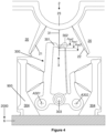
- the stiffness selection device 300 here takes the form of a device for modifying the active length of the elastic blade 31 as illustrated in the Figure 4 .
- the device 300 comprises a pair of clamps 301, 302 gripping the elastic blade. 31 and capable of moving in the longitudinal direction of said blade 31 so as to reach three predefined stable positions Pos1, Pos2, Pos3 making it possible to define the stiffnesses k31, k32, k33 respectively.
- the selection device 300 may comprise a pair of clamps 301, 302 determining an active length, in particular three active lengths, of the elastic return system 10.
- the clamps 301, 302 are each mounted on the monolithic structure 900, in particular on a frame 304 of the monolithic structure 900, by means of elastic blades, and are returned against the elastic blade 31 under the effect of a tenon 303 which makes it possible to act against the elastic blades by urging the clamps 301, 302 substantially to pivot about their respective axis of rotation A301, A302.
- the clamps 301, 302 are provided to clamp the blade elastic 31 with sufficient force to avoid any mechanical play during oscillations of the oscillator. This force must however be determined so as to allow the movement of the clamps 301, 302 to move from one stable position to another stable position. Typically, this force can be between 0.1 mN and 10 mN depending on the dimensions of the regulating system.
- the clamps 301, 302 are capable of being held in one or other of the positions Pos1, Pos2, Pos3 thanks to the toothed structure 305 provided for positioning the selection beak 306 connected to the frame 304 by means of a flexible structure.
- the toothed structure 305 comprises 3 tooth hollows within which the beak 306 is capable of coming to position itself under the effect of the tenon 307 which makes it possible to constrain the flexible structure connecting the beak 306 to the frame 304 so as to maintain said beak 306 in contact with the toothed structure 305.
- the Figure 5 represents the selection device 300 in black. This is part of the monolithic structure 900 intended to be attached to the frame 6 of the movement 2000, in particular to a roughing-out.
- This selection device 300 is actuated periodically by the actuating device 500.
- this actuating device 500 makes it possible to position the pair of clamps 301, 302 according to one of the three stable positions Pos1, Pos2, Pos3 by moving, or not, the selection beak 306 opposite the toothed structure 305.
- the actuating device 500 is in the form of an electromechanical device comprising an electrical energy source 501 and an electromechanical actuator 502.
- the electrical energy source 501 makes it possible to deliver an electrical voltage, positive or negative, to the electromechanical actuator 502 and thus makes it possible to act on the frame 304 by means of an arm 503 articulated by a flexible guide, in particular by pivoting around a virtual axis of rotation A503.
- This arm 503 is respectively connected to the actuator 502 and to the frame 304 by multiple elastic structures.
- the arm 503 is also included within the monolithic structure 900, and the actuator 502 is intended to be arranged within a housing 504 of this same monolithic structure.
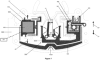
- Figure 7 represents a view of the elements of the actuation device 500 formed on the structure 900. These are represented in black, like those of the selection device 300.
- the actuator 502 is represented by hatching.
- the actuator 502 is designed to be actuated in a direction parallel or substantially parallel to the longitudinal direction of the blade 31, in a first or second direction depending on the sign of the electrical voltage delivered by the electrical energy source 501.
- this voltage is delivered only punctually and periodically so as to exclusively move the selection beak 306 with respect to the toothed structure 305, the beak being held in position against the structure 305 under the effect of the tenon 307 and under the effect of the various elastic structures which make it possible to ensure that the beak 306 remains hooked between two teeth of the toothed structure 305.
- the different positions are advantageously mechanically stable. Such a design therefore makes it possible to minimize the consumption of electrical energy supplied by the electrical energy source 501 used to power the actuation device 500, but also a possible comparison device 400 which will be described below.
- the actuator 502 actuates the pair of clamps 301, 302 exclusively when the pair of clamps 301, 302 is in position Pos1 ( Figure 6a ), as described below.
- the beak 306 is located between two teeth arranged in the center of the toothed structure 305.
- the actuator 502 operates in a first direction illustrated by a solid arrow S1 of the Figure 7
- the beak is driven in a second direction illustrated by a solid arrow S1', opposite to the first direction, due to the location of the articulation axis A503 of the arm 503.
- Such an action thus induces the movement of the beak 306 so that the pair of clamps 301, 302 can be positioned in position Pos3 ( Figure 6c ).
- the sign of the voltage supplied by the electrical energy source 501, and therefore the direction of movement S1, S2 (or S1', S2') of the actuator 502 or the nozzle 306, is a function of a value VD which results from a comparison device 400.
- the comparison device 400 may be at least partially electronic. This device makes it possible to establish at least one difference value VD between the rotation period P of the mobile 821 and a rotation reference period Pref of said mobile 821 given by a counting device 200.
- the counting device 200 comprises a second oscillator 210 having a frequency F1 significantly higher than the frequency f1 of the first oscillator 100.
- thermo-compensated oscillator having a frequency of the order of several tens or hundreds of kHz or MHz and having excellent stability, which thus makes it possible to define a rotation reference period Pref which can be considered as the period that the mobile 821 should ideally have in all circumstances.
- the electrical energy source 501 does not deliver any electrical voltage, so that the actuator 502 does not actuate the pair of clamps 301, 302.
- the pair of clamps 301, 302 remains held in position Pos1 ( Figure 6a ).
- x is a real number, a a negative real number, and b a positive real number.
- the electrical energy source 501 delivers an electrical current with a voltage of a first sign, so that the actuator 501 actuates in a first direction so as to move the pair of clamps 301, 302 into the position Pos2, which allows the movement to correct a delay displayed by the display element 71.
- the electrical energy source 501 delivers an electrical current with a voltage of a second sign, opposite to the first sign, so that the actuator 501 actuates in a second direction, opposite to the first direction, so as to move the pair of clamps 301, 302 into the position Pos3, which allows the movement to correct an advance displayed by the display element 71.
- the comparison device 400 is arranged so as to compare a rotation period P of the mobile 821 of the finishing gear 82 and a reference rotation period Pref of said mobile 821.
- figure 8 represents a flowchart summarizing these different scenarios.
- the comparison device 400 comprises a lever 404 and a wheel set 401 kinematically connected to the wheel set 821 of the finishing gear train 82 of the movement 2000.
- the gear ratio here is 1, so that this wheel set 401 also has a rotation period P equal to that of the wheel set 821 (equal to or of the order of 60 seconds knowing that the mobile 821 is here a seconds mobile).
- the mobile 401 comprises a wheel 402 provided with a tenon 403 intended to cooperate periodically with a lever 404 so as to drive it in rotation against a spring element 405 returning the lever to a predefined position when the tenon is not in contact with the lever.
- this rocker comprises a beak 404a provided to cooperate with the tenon 403, as well as an arm 404b provided to come into contact with a pin 406 acting as a contactor when the beak 404a is lifted by the tenon 403.
- the loss of contact between the arm 404b and the pin 406 makes it possible to determine, at regular or substantially regular intervals (here every minute), the rotation period P. This information is then transmitted to an integrated circuit 407 of the comparison device 400, which is likely to be taken into consideration under the effect of the servo-control device 600.
- the servo device 600 makes it possible to reposition, in particular periodically, the pair of clamps 301, 302 in position Pos1.
- the servo device 600 shown in the figures 10 And 11 comprises a lever 602 actuated by the finishing gear train 82 of the 2000 movement, as well as a tenon 601 fixed to the toothed structure 305 of the monolithic structure 900.
- This lever 602 is designed to act periodically on the tenon 601 so as to retract the selection beak 306 of the toothed structure 305 which is mounted on the structure 900 by means of a flexible structure.
- the rocker 602 is designed to act punctually on the tenon 601 in a direction perpendicular to the direction of movement of the actuator 502, and in a direction S3, which makes it possible to move the toothed structure 305 away from the beak 306 and thus punctually disengage the beak 306 from the teeth 305.
- the beak then returns to position under the effect of the restitution of the flexible structures respectively connecting the beak 306 to the frame 304 and the toothed structure 305 to the rest of the structure 900. Due to the specific arrangement and conformation of the different elastic structures, the pair of clamps 301, 302 returns to position Pos1.
- the lever 602 is designed to be returned by a spring 603 and to be actuated by a cam 604 mounted on a wheel 605 itself mounted in derivation from the finishing gear train 82, for example from a center wheel 822 to which an hour hand 72 of the display device 700 is linked.
- the servo-control device 600 thus has the advantage of allowing the pair of clamps 301, 302 to be put back into position Pos1, and this periodically (in the embodiment described), without intervention from the actuating device and/or the wearer of the watch. Furthermore, the servo-control device also has the advantage of allowing a unitary action of displacement of the actuator 502 of a given amplitude, and this whatever the direction of actuation (S1, S2). Such a construction therefore makes it possible to minimize the consumption of electrical energy supplied by a primary source, because the action of the actuator is punctual and of a predefined amplitude. Such a construction is notably simpler to implement and more reliable than a construction in which the actuator 502 would be required to carry out all possible transitions between the three stable positions.
- the mobile 821 is regulated exclusively by the first oscillator 100, with an elastic return system 10 maintained or returned to position Pos1 under the effect of the device 600 so that the first oscillator 100 has a nominal frequency f1.
- the mobile 821 can be regulated by the first oscillator 100, independently in particular of the devices 200, 400.
- the servo device 600 has the advantage of being integrated within the mechanical or automatic movement 2000, in particular with regard to the elements 601, 602, 603, 604, 605.
- the actuating device 500 acting on the frequency selection device 300 can be controlled by the servo device 600.
- the regulating system 1000 also advantageously comprises an initialization device 800 of the counting device 200.
- the latter can advantageously be activated by an adjustment mechanism 91 of the display device 700 of the timepiece 3000, for example an adjustment mechanism integrated within the movement 2000.
- the counting device 200 is initialized in order to take into account the new effective position of the display device 700.
- the actuating device 500 can be inhibited over a given period following the action of the initialization device 800.
- the monolithic structure 900 is made of monocrystalline silicon. This advantageously makes it possible to group within it a large number of elements taking part in the regulating system 1000, in particular the devices 300, 500, 600.
- the structure 900 may be designed to be attached to the frame 6 of the mechanical or automatic movement 2000.
- the other elements of the regulating system 1000 may also be an integral part of the movement 2000.
- these other elements, in particular the electronic components, may be arranged on the periphery of the movement 2000, within the timepiece 3000.
- the comparison device 400 acts every minute or substantially every minute.
- a value VD can be established at this same frequency.
- the value VD established just before or just after the contact between the rocker 602 and the tenon 606 (which takes place every hour or substantially every hour) is taken into consideration by the actuating device 500.
- the value VD can also be established at any other frequency.
- the movement 2000 can be regulated exclusively by the first oscillator 100 (it is then a mechanical or automatic movement) or by the entire regulating system 1000.
- the gear chain 82 in particular the mobile 821, is at least partially regulated by the first oscillator 100.
- the inertial element 4 of the first oscillator 100 is an assembled balance comprising a balance 41 provided with screws or weights 43a which can be moved in order to allow fine adjustment of the rate of the movement 2000, of the order of a few seconds per day as illustrated in the Figure 3 .
- These screws or weights are for example fixed in a movable manner relative to a serge 410 of the balance 41.
- These screws or weights can for example be manipulated by a watchmaker when the balance is stopped, by means of a key or a screwdriver which allows them to be moved (by bringing them closer to or moving them away from the axis A4).
- These tools are generally equipped with means which allow the advance or recoil of the screw or weight to be indicated in order to allow a particularly fine adjustment of the rate of the movement.
- the rim 410 of the balance 41 advantageously comprises two pairs of weights 43a, 43b and 44a, 44b having distinct conformations, in particular different masses.
- the weights 43a, 43b are longer than the weights 44a, 44b.
- the weights 44a, 44b induce a finer adjustment of the than the weights 43a, 43b.
- the weights are moved in pairs in order to best maintain the balance of the assembled balance wheel 4.
- these weights allow adjustment of the rate of the 2000 movement over a range of ⁇ 2s/day.
- the actuation devices 500 and servo-control devices 600 act every hour or substantially every hour on the stiffness selection device 300. It is possible to provide an action at any other frequency.
- the devices for comparison, actuation of the selection device, and servocontrol of the selection device act periodically, namely at regular intervals.
- the comparison device and/or the actuation device and/or the servocontrol device are activated at a particular time, not necessarily periodic, for example when a control unit deems it appropriate in the event of a deviation in rate considered too significant.
- the wearer of the watch can himself activate the actuation device if he notices that the display device of the timepiece is moving ahead or behind.
- the actuation device can be a purely mechanical device, for example controlled by the wearer of the watch by means of pushers or correctors.
- the servo-control device can impose a nominal oscillation frequency on the first mechanical oscillator after the control unit or the wearer of the watch has intervened, this servo-control device being controlled by the gear train (at least partially) regulated by the first oscillator.
- the actuating device can be activated on demand, by a control unit or by the wearer himself.
- the activation of the servo-control device namely the connection between the finishing gear train and the tenon 601 fixed to the toothed structure 305 of the monolithic structure 900, for example by means of the contacting of the lever 602 with the cam 604 under the effect of an additional clutch system.
- the lever 602 would then be disconnected from the cam 604 when the actuating device is not actuated, for example during the conventional operation of the movement 2000.
- the comparison device 400 rests on a wheel set 401 having a rotation period P equal to that of the wheel set 821 of the chain 82 of the movement 2000 (equal to or of the order of 60 seconds, knowing that the wheel set 821 is in particular a seconds wheel set).
- the display element or the seconds hand 71 of the display device 700 is not essential for the proper functioning of the regulating system.
- the comparison device 400 could rest on the display element or the seconds hand 71 of the display device 700.
- the comparison device could comprise means (optical, for example) making it possible to identify the actual position of the display element or second hand 71 at a given time.
- the modification of the frequency of the first mechanical oscillator involves a modification of the stiffness of the elastic return system, in particular by a modification of the active length of the third elastic return element. It is nevertheless possible to envisage other means of modifying the frequency of the first oscillator.
- it is possible to modify the environment of the first mechanical oscillator so as to vary the aerodynamic friction to which the oscillating mass of the inertial element is subjected (as taught in the patent CH109521 ).
- a fairing could for example be provided to surround the oscillating mass of the inertial element and the conformation of the fairing (its geometry and/or its arrangement on the movement frame) could be modified under the effect of the servo-control and/or actuation devices.
- the electromagnetic environment of the first mechanical oscillator can also be modified under the effect of the servo-control and/or actuation devices, so as to vary its oscillation frequency.
- the mass elements could, for example, be made of piezoelectric material or magnetostrictive material (as taught within the application EP3120199 ).
- servo device modifies the frequency of the first oscillator according to a first technique and the actuator device modifies the frequency of the first oscillator according to a second technique.
- the regulating system implements the first step of operation according to the main mode in which the first mechanical oscillator 100 oscillates at the first predetermined frequency f1.
- the servo-control, comparison and actuation devices preferably act periodically, namely at regular intervals. In other words, these steps are repeated more particularly at regular intervals.
- the second step E2 is repeated periodically every minute or substantially every minute (first period P1), while the first and third steps E1, E3 are repeated periodically every hour or substantially every hour (second period P2).
- the second actuation step may only be implemented when the value VD is not included in the predefined tolerance range [a; b] as mentioned previously.
- the comparison step is advantageously implemented by the comparison device 400.
- the comparison step can be implemented at a regular time interval and/or at an interval defined by a watch movement 2000, for example every minute or every hour.
- the comparison step can be implemented at the request of a user or wearer of the timepiece.
- the user can act on an organ of the timepiece, such as a push button which activates the comparison device and/or the actuating device.
- the fourth step occurs at a regular time interval and/or at an interval defined by a 2000 clockwork movement, for example every hour.
- the second step may comprise or consist of a step of moving the pair of immobilizing clamps along the flexible blade.
- the solutions described are remarkable in that they comprise a servo-control device which makes it possible to impose a predetermined oscillation frequency f1 on the mechanical oscillator thanks to which the timepiece intrinsically has excellent precision.
- this servo-control device is controlled by a gear train, in particular a finishing gear train which drives the display device of the watch, which is at least partially regulated by said mechanical oscillator.
- this servo-control device could also be controlled by other means or devices, in particular in the case of a movement within which the rate correction is effective upstream of the fourth step occurring at regular time intervals and/or at defined intervals.
- this servo-control device can be at least controlled by a gear train, in particular a finishing gear train.
- this servo-control device makes it possible to impose a pivot frequency f1 on the mechanical oscillator, called “nominal”, which allows adequate operation of the mechanical oscillator, and this independently of the other devices 300, 400, 500, 600. Furthermore, according to the embodiment described, this servo-control device also has the advantage of allowing the selection of at least one other oscillation frequency (f2, f3) of the mechanical oscillator, by instructing the actuating device allowing the selection of at least one other oscillation frequency.
- the regulating system comprises a first mechanical oscillator whose “nominal” frequency can be modified, possibly at regular intervals, but which can be restored, possibly at regular intervals, under the effect of a servo-control device controlled by a gear train, in particular a finishing gear train, which is at least partially regulated by said first mechanical oscillator.
- “nominal” frequency (f1) we mean a frequency of the first mechanical oscillator determined during the design and/or during the assembly of said first oscillator in order to achieve a target chronometric precision when the gear train, in particular the finishing gear train, is regulated exclusively by said first oscillator.
- This assembly of the first oscillator may for example require a targeted adjustment of the stiffness, in particular of the active length, of a return element of the elastic return system taking part in the first oscillator, or by a targeted adjustment of weights arranged on an inertial element taking part in the first oscillator.
- the frequency f1 of the system is a frequency such that that the watch movement and/or the timepiece can be certified, in particular can obtain a chronometer certification by the COSC, or even such that the timepiece can obtain the “superlative chronometer” certification from the applicant.
- the regulating system comprises a first mechanical oscillator whose frequency f1 can be modified (by the actuating device of the selection device) but is then restored (by the servo-control device of the selection device), in particular restored autonomously by an element directly actuated by the finishing gear.
- the servo-control device makes it possible to impose a predetermined oscillation frequency on the mechanical oscillator, this device being controlled by a gear train, in particular the finishing gear train linked to a display device of the watch, which is at least partially regulated by said mechanical oscillator, and not by a third-party device or by the wearer of the watch.
Landscapes
- Physics & Mathematics (AREA)
- General Physics & Mathematics (AREA)
- Electromagnetism (AREA)
- Engineering & Computer Science (AREA)
- Power Engineering (AREA)
- Electric Clocks (AREA)
- Electromechanical Clocks (AREA)
Priority Applications (10)
| Application Number | Priority Date | Filing Date | Title |
|---|---|---|---|
| EP23213488.2A EP4564106A1 (de) | 2023-11-30 | 2023-11-30 | Reguliersystem für eine uhr |
| EP23838147.9A EP4643187A1 (de) | 2022-12-28 | 2023-12-28 | Regulierungssystem für uhrwerk |
| CN202380093744.XA CN120677443A (zh) | 2022-12-28 | 2023-12-28 | 用于钟表机芯的调节系统 |
| PCT/EP2023/087923 WO2024141600A1 (fr) | 2022-12-28 | 2023-12-28 | Système réglant pour mouvement horloger |
| EP23838146.1A EP4643186A1 (de) | 2022-12-28 | 2023-12-28 | Regulierungssystem für uhrwerk |
| JP2025538241A JP2026500431A (ja) | 2022-12-28 | 2023-12-28 | 時計ムーブメントの調速システム |
| PCT/EP2023/087924 WO2024141601A1 (fr) | 2022-12-28 | 2023-12-28 | Système réglant pour mouvement horloger |
| JP2024206159A JP2025088753A (ja) | 2023-11-30 | 2024-11-27 | 時計の調速システム |
| US18/961,765 US20250181036A1 (en) | 2023-11-30 | 2024-11-27 | Regulating system for a timepiece |
| CN202411740104.6A CN120065674A (zh) | 2023-11-30 | 2024-11-29 | 用于钟表的调校系统 |
Applications Claiming Priority (1)
| Application Number | Priority Date | Filing Date | Title |
|---|---|---|---|
| EP23213488.2A EP4564106A1 (de) | 2023-11-30 | 2023-11-30 | Reguliersystem für eine uhr |
Publications (1)
| Publication Number | Publication Date |
|---|---|
| EP4564106A1 true EP4564106A1 (de) | 2025-06-04 |
Family
ID=89029736
Family Applications (1)
| Application Number | Title | Priority Date | Filing Date |
|---|---|---|---|
| EP23213488.2A Pending EP4564106A1 (de) | 2022-12-28 | 2023-11-30 | Reguliersystem für eine uhr |
Country Status (4)
| Country | Link |
|---|---|
| US (1) | US20250181036A1 (de) |
| EP (1) | EP4564106A1 (de) |
| JP (1) | JP2025088753A (de) |
| CN (1) | CN120065674A (de) |
Citations (9)
| Publication number | Priority date | Publication date | Assignee | Title |
|---|---|---|---|---|
| CH6444A (fr) | 1893-04-21 | 1893-08-15 | Amez Droz Louis Frederic | Nouveau système de régulateur pour échappements |
| CH109521A (fr) | 1924-07-16 | 1925-04-01 | Aegler S A Rolex Watch Co | Dispositif régulateur de mouvement de montre. |
| CH321947A (fr) | 1955-08-20 | 1957-05-31 | Etienne Fernand | Dispositif de réglage de la position de la raquette d'une pièce d'horlogerie |
| EP1158373A1 (de) | 1999-12-24 | 2001-11-28 | Seiko Instruments Inc. | Mechanische uhr mit einem reglerbetätigungsmechanismus |
| EP1164441A1 (de) | 1999-12-24 | 2001-12-19 | Seiko Instruments Inc. | Mechanische uhr mit einer räderwerkssteuerungseinheit |
| CH711303A1 (fr) * | 2015-07-09 | 2017-01-13 | Soprod Sa | Dispositif de correction pour un mouvement horloger mécanique. |
| EP3120199A2 (de) | 2014-03-21 | 2017-01-25 | Hublot S.A., Genève | Rotierendes uhrenelement, uhrenoszillator |
| EP3629103A1 (de) * | 2018-09-28 | 2020-04-01 | The Swatch Group Research and Development Ltd | Uhr, die ein mechanisches uhrwerk umfasst, dessen ganggenauigkeit durch eine elektronische vorrichtung reguliert wird |
| EP3842876A1 (de) * | 2019-12-24 | 2021-06-30 | The Swatch Group Research and Development Ltd | Uhr, die mit einem mechanischen uhrwerk und einer vorrichtung zur korrektur der angezeigten stunde ausgestattet ist |
Family Cites Families (1)
| Publication number | Priority date | Publication date | Assignee | Title |
|---|---|---|---|---|
| EP3339982B1 (de) * | 2016-12-23 | 2021-08-25 | The Swatch Group Research and Development Ltd | Regulierung durch mechanisches bremsen eines mechanischen oszillators einer uhr |
-
2023
- 2023-11-30 EP EP23213488.2A patent/EP4564106A1/de active Pending
-
2024
- 2024-11-27 US US18/961,765 patent/US20250181036A1/en active Pending
- 2024-11-27 JP JP2024206159A patent/JP2025088753A/ja active Pending
- 2024-11-29 CN CN202411740104.6A patent/CN120065674A/zh active Pending
Patent Citations (9)
| Publication number | Priority date | Publication date | Assignee | Title |
|---|---|---|---|---|
| CH6444A (fr) | 1893-04-21 | 1893-08-15 | Amez Droz Louis Frederic | Nouveau système de régulateur pour échappements |
| CH109521A (fr) | 1924-07-16 | 1925-04-01 | Aegler S A Rolex Watch Co | Dispositif régulateur de mouvement de montre. |
| CH321947A (fr) | 1955-08-20 | 1957-05-31 | Etienne Fernand | Dispositif de réglage de la position de la raquette d'une pièce d'horlogerie |
| EP1158373A1 (de) | 1999-12-24 | 2001-11-28 | Seiko Instruments Inc. | Mechanische uhr mit einem reglerbetätigungsmechanismus |
| EP1164441A1 (de) | 1999-12-24 | 2001-12-19 | Seiko Instruments Inc. | Mechanische uhr mit einer räderwerkssteuerungseinheit |
| EP3120199A2 (de) | 2014-03-21 | 2017-01-25 | Hublot S.A., Genève | Rotierendes uhrenelement, uhrenoszillator |
| CH711303A1 (fr) * | 2015-07-09 | 2017-01-13 | Soprod Sa | Dispositif de correction pour un mouvement horloger mécanique. |
| EP3629103A1 (de) * | 2018-09-28 | 2020-04-01 | The Swatch Group Research and Development Ltd | Uhr, die ein mechanisches uhrwerk umfasst, dessen ganggenauigkeit durch eine elektronische vorrichtung reguliert wird |
| EP3842876A1 (de) * | 2019-12-24 | 2021-06-30 | The Swatch Group Research and Development Ltd | Uhr, die mit einem mechanischen uhrwerk und einer vorrichtung zur korrektur der angezeigten stunde ausgestattet ist |
Also Published As
| Publication number | Publication date |
|---|---|
| CN120065674A (zh) | 2025-05-30 |
| JP2025088753A (ja) | 2025-06-11 |
| US20250181036A1 (en) | 2025-06-05 |
Similar Documents
| Publication | Publication Date | Title |
|---|---|---|
| EP2453322B1 (de) | Schneller Korrektor einer Zeitgrößenanzeige für Uhr | |
| WO2018095997A2 (fr) | Resonateur rotatif a guidage flexible entretenu par un echappement libre a ancre | |
| EP3435176B1 (de) | Drehmomentglättung für uhr mit einem schlagwerkmechanismus, insbesondere mit schlagwerkmechanismus | |
| EP3037894B1 (de) | Mechanismus und Verfahren zur Geschwindigkeitseinstellung in einem Uhrwerk | |
| EP3599516B1 (de) | Retrogrades tourbillon oder karussell eines uhrwerks | |
| EP2613205A2 (de) | Regulierorgan für Armbanduhr oder Chronografen | |
| EP3059642A1 (de) | Uhrmechanismus | |
| CH710925A2 (fr) | Mécanisme d'échappement. | |
| CH713530A2 (fr) | Echappement, mouvement de pièce d'horlogerie et pièce d'horlogerie. | |
| EP4564106A1 (de) | Reguliersystem für eine uhr | |
| EP2802941B1 (de) | Einstellelement für eine mechanische uhr | |
| EP3825780A1 (de) | Mechanische uhreinstellvorrichtung, die einen uhrhemmungsmechanismus mit konstanter kraft umfasst | |
| CH705967B1 (fr) | Mécanisme d'horlogerie comprenant un organe réglant comprenant un oscillateur vibrant, et mouvement d'horlogerie comprenant un tel mécanisme. | |
| EP4432020A1 (de) | Uhrwerk | |
| CH705970B1 (fr) | Mécanisme d'horlogerie comprenant un oscillateur vibrant. | |
| EP3671360A1 (de) | Aufziehvorrichtung mit stossdämpfungssystem | |
| CH715196A2 (fr) | Mouvement d'horlogerie comportant un bras porteur d'un satellite que comporte un tourbillon ou carrousel. | |
| EP3599515A1 (de) | Antriebsmechanismus für uhrwerk | |
| EP4390574A1 (de) | Chronographenmechanismus für uhrwerk und uhr mit einem solchen mechanismus | |
| EP4421567A1 (de) | Auslösemechanismus eines uhrwerksmechanismus und uhr mit solch einem auslösemechanismus | |
| EP3822711A1 (de) | Uhrwerkmechanismus, der eine mit einer angetriebenen feder zusammenwirkende treibende feder umfasst | |
| CH720361A2 (fr) | Mécanisme de chronographe pour mouvement d'horlogerie | |
| EP4390555A1 (de) | Konstantkrafthemmungsmechanismus für uhrwerk | |
| CH705969A1 (fr) | Organe réglant pour montre ou chronographe. | |
| CH705968B1 (fr) | Mouvement d'horlogerie et chronographe comprenant un tel mouvement. |
Legal Events
| Date | Code | Title | Description |
|---|---|---|---|
| PUAI | Public reference made under article 153(3) epc to a published international application that has entered the european phase |
Free format text: ORIGINAL CODE: 0009012 |
|
| STAA | Information on the status of an ep patent application or granted ep patent |
Free format text: STATUS: THE APPLICATION HAS BEEN PUBLISHED |
|
| AK | Designated contracting states |
Kind code of ref document: A1 Designated state(s): AL AT BE BG CH CY CZ DE DK EE ES FI FR GB GR HR HU IE IS IT LI LT LU LV MC ME MK MT NL NO PL PT RO RS SE SI SK SM TR |
|
| P01 | Opt-out of the competence of the unified patent court (upc) registered |
Free format text: CASE NUMBER: UPC_APP_8162_4564106/2025 Effective date: 20250927 |
|
| STAA | Information on the status of an ep patent application or granted ep patent |
Free format text: STATUS: REQUEST FOR EXAMINATION WAS MADE |
|
| 17P | Request for examination filed |
Effective date: 20251202 |