EP3629454A1 - Verfahren zur herstellung eines rotors für eine elektrische rotierende maschine - Google Patents
Verfahren zur herstellung eines rotors für eine elektrische rotierende maschine Download PDFInfo
- Publication number
- EP3629454A1 EP3629454A1 EP18197408.0A EP18197408A EP3629454A1 EP 3629454 A1 EP3629454 A1 EP 3629454A1 EP 18197408 A EP18197408 A EP 18197408A EP 3629454 A1 EP3629454 A1 EP 3629454A1
- Authority
- EP
- European Patent Office
- Prior art keywords
- rotor
- permanent magnet
- magnetic field
- magnetic
- cold gas
- Prior art date
- Legal status (The legal status is an assumption and is not a legal conclusion. Google has not performed a legal analysis and makes no representation as to the accuracy of the status listed.)
- Withdrawn
Links
Images






Classifications
-
- H—ELECTRICITY
- H02—GENERATION; CONVERSION OR DISTRIBUTION OF ELECTRIC POWER
- H02K—DYNAMO-ELECTRIC MACHINES
- H02K1/00—Details of the magnetic circuit
- H02K1/06—Details of the magnetic circuit characterised by the shape, form or construction
- H02K1/22—Rotating parts of the magnetic circuit
- H02K1/27—Rotor cores with permanent magnets
- H02K1/2786—Outer rotors
- H02K1/2787—Outer rotors the magnetisation axis of the magnets being perpendicular to the rotor axis
- H02K1/2789—Outer rotors the magnetisation axis of the magnets being perpendicular to the rotor axis the rotor consisting of two or more circumferentially positioned magnets
- H02K1/2791—Surface mounted magnets; Inset magnets
-
- H—ELECTRICITY
- H02—GENERATION; CONVERSION OR DISTRIBUTION OF ELECTRIC POWER
- H02K—DYNAMO-ELECTRIC MACHINES
- H02K15/00—Processes or apparatus specially adapted for manufacturing, assembling, maintaining or repairing of dynamo-electric machines
- H02K15/02—Processes or apparatus specially adapted for manufacturing, assembling, maintaining or repairing of dynamo-electric machines of stator or rotor bodies
- H02K15/03—Processes or apparatus specially adapted for manufacturing, assembling, maintaining or repairing of dynamo-electric machines of stator or rotor bodies having permanent magnets
-
- H—ELECTRICITY
- H02—GENERATION; CONVERSION OR DISTRIBUTION OF ELECTRIC POWER
- H02K—DYNAMO-ELECTRIC MACHINES
- H02K15/00—Processes or apparatus specially adapted for manufacturing, assembling, maintaining or repairing of dynamo-electric machines
-
- H—ELECTRICITY
- H02—GENERATION; CONVERSION OR DISTRIBUTION OF ELECTRIC POWER
- H02K—DYNAMO-ELECTRIC MACHINES
- H02K7/00—Arrangements for handling mechanical energy structurally associated with dynamo-electric machines, e.g. structural association with mechanical driving motors or auxiliary dynamo-electric machines
- H02K7/18—Structural association of electric generators with mechanical driving motors, e.g. with turbines
- H02K7/1807—Rotary generators
- H02K7/1823—Rotary generators structurally associated with turbines or similar engines
- H02K7/183—Rotary generators structurally associated with turbines or similar engines wherein the turbine is a wind turbine
- H02K7/1838—Generators mounted in a nacelle or similar structure of a horizontal axis wind turbine
-
- Y—GENERAL TAGGING OF NEW TECHNOLOGICAL DEVELOPMENTS; GENERAL TAGGING OF CROSS-SECTIONAL TECHNOLOGIES SPANNING OVER SEVERAL SECTIONS OF THE IPC; TECHNICAL SUBJECTS COVERED BY FORMER USPC CROSS-REFERENCE ART COLLECTIONS [XRACs] AND DIGESTS
- Y02—TECHNOLOGIES OR APPLICATIONS FOR MITIGATION OR ADAPTATION AGAINST CLIMATE CHANGE
- Y02E—REDUCTION OF GREENHOUSE GAS [GHG] EMISSIONS, RELATED TO ENERGY GENERATION, TRANSMISSION OR DISTRIBUTION
- Y02E10/00—Energy generation through renewable energy sources
- Y02E10/70—Wind energy
- Y02E10/72—Wind turbines with rotation axis in wind direction
Definitions
- the invention relates to a method for producing a rotor for an electric rotating machine with a magnetic field-guiding, in particular eddy current suppressing, rotor element and at least one permanent magnet.
- the invention also relates to a rotor for an electric rotating machine, which is produced using such a method.
- the invention further relates to an electric rotating machine with at least one such rotor.
- the invention relates to a wind power plant with at least one such rotating electrical machine.
- Electrical rotating machines are designed, for example, as permanently excited synchronous machines, in particular as permanently excited three-phase synchronous machines.
- Such permanently excited three-phase synchronous machines can be operated, for example, as a motor or as a generator.
- a generator is used, for example, as a wind generator in a wind power plant, with direct drive wind generators in particular having a diameter of several meters.
- Permanently excited synchronous machines have a rotor with permanent magnets, which are connected to a magnetic field-guiding, in particular eddy current suppressing, rotor element, for example a rotor laminated core or a solid rotor yoke, in order to secure the magnets during operation of the rotating electrical machine. Securing the magnets, particularly in the case of very large machines, is very complex and expensive.
- the disclosure DE 10 2010 041 593 A1 describes a magnetic pole cover for a pole of a rotor of an electrical machine, which has a first side plate, a second side plate, a first side wall, a second side wall, an opening and a central covering area between the first side wall and the second side wall.
- the disclosure EP 2 587 633 A1 describes a magnetic cover plate module for the individual positioning and protection of permanent magnets on a rotor yoke for wind turbines.
- the magnet module has a magnet cover plate made of a soft magnetic material for individual covering of the permanent magnets, a non-magnetic plate being permanently attached to the magnet cover plate.
- the non-magnetic plate has means for fastening the magnetic cover plate module to an outer surface of the rotor yoke, the fastening means being removable in order to enable the cover plate module to be assembled and disassembled separately.
- a magnetic extender is arranged on an inner surface of the rotor yoke to guide the magnetic flux and to avoid stray fluxes.
- the disclosure DE 10 2012 006 248 A1 describes a squirrel-cage rotor including a core, a plurality of slot holes formed in the core and extending along an axis of rotation of the core, conductive bars disposed in the slot holes, and a pair of conductive end rings disposed at both ends of the core and are connected to each other by means of the conductive rods. At least one of the conductive rods and the pair of conductive end rings is constructed by a cover layer material that is formed by spraying solid-state conductor particles.
- EP 2 555 385 A1 describes a permanent magnet arrangement with a base plate and at least one permanent magnet which is attached to the base plate is.
- the at least one permanent magnet is covered by a plastic hood.
- EP 1 844 181 A1 describes a method for coating a workpiece using cold gas spraying.
- a cold gas spray nozzle is used, which generates a particle beam directed at the surface.
- the invention has for its object to provide a method for producing a rotor for an electric rotating machine with a magnetic field-guiding, in particular eddy current suppressing, rotor element and at least one permanent magnet, which is simpler and cheaper in comparison to the prior art.
- the object is achieved according to the invention by a method of the type mentioned at the outset, the permanent magnet being connected to the rotor element carrying the magnetic field by means of an additive manufacturing method.
- the object is achieved according to the invention by a rotor for an electrical rotating machine, which is produced using such a method.
- an electrical rotating machine with at least one such rotor.
- the object is achieved according to the invention by a wind power plant with at least one such rotating electrical machine.
- the invention is based on the consideration of simplifying the manufacture of a rotor by fastening at least one permanent magnet with the aid of an additive manufacturing process.
- additive manufacturing processes are, for example, powder bed processes such as selective laser melting or selective laser sintering, free space processes such as cladding, liquid material processes such as stereolithography, or other layer build-up processes such as 3D screen printing.
- the at least one permanent magnet is attached to a magnetic field-carrying rotor element with the aid of the additive manufacturing process in order to secure the permanent magnets during operation, the magnetic field-carrying rotor element being made of a soft magnetic material, in particular steel, and being designed as a laminated core or as a solid rotor yoke.
- the attachment of the permanent magnets using an additive manufacturing process simplifies the machining of the rotor surface and reduces the number of process steps for manufacturing the rotor, thereby saving costs.
- the at least one permanent magnet is magnetized before being connected to the rotor element carrying the magnetic field. Magnetization of the permanent magnet before connection to the magnetic field-carrying rotor element simplifies the manufacture of the rotor.
- the permanent magnet is connected to the magnetic field-carrying rotor element by means of cold gas spraying.
- cold gas spraying With the help of cold gas syringes, compared to other additive manufacturing processes, thick layers, for example in the millimeter range and in the centimeter range, can be produced very quickly and geometrically very flexibly. Since the material applied by means of cold gas spraying is not melted, but is deformed by its kinetic energy and thus forms a tight and firmly adhering layer, the permanent magnet and the magnetic field-carrying rotor element are only exposed to low temperature loads. They are also thermally induced Tensions, especially in the area of the connection, largely avoided.
- the permanent magnet is particularly advantageously connected to the magnetic field-carrying rotor element via connecting means, the connecting means comprising, in particular, electrically conductive, solid particles which are sprayed on by means of cold gas spraying for connecting the permanent magnet to the magnetic field-carrying rotor element.
- the connecting means produce a stable connection between the permanent magnet and the rotor element carrying the magnetic field in a simple manner by forming a dense and firmly adhering layer.
- Cold gas spraying offers great flexibility in terms of shape, thickness and material.
- the solid particles of the connecting means are made from a non-magnetic metallic material, in particular from a stainless steel.
- non-magnetic solid particles are advantageous for the flow guidance in the machine, so that, for example, stray fluxes are at least minimized.
- the connecting means comprise a cover from which the permanent magnet is at least partially covered.
- the cover secures the permanent magnet, especially in the radial direction. Furthermore, the cover protects the permanent magnet from external influences.
- the cover is particularly advantageously made from a non-magnetic metallic material, in particular from stainless steel.
- a non-magnetic metallic material simplifies the assembly of the cover, in particular in the case of a magnetized permanent magnet.
- the cover is constructed from solid particles which are sprayed on by means of cold gas spraying.
- the permanent magnet is protected in a simple and inexpensive manner by spraying on the cover, since, for example, the permanent magnet is not cast in the cover.
- Cold gas spraying offers great flexibility, for example with regard to the material thickness and shape of the cover.
- the solid particles of the cover are sprayed directly onto the permanent magnet.
- the direct spraying of the solid particles also simplifies the manufacture of the rotor.
- the connecting means comprise a base plate which is arranged between the permanent magnet and the rotor element carrying the magnetic field.
- the cover is particularly advantageously connected to the base plate by means of cold gas spraying. Since the material applied using cold gas spraying is not melted, but rather is deformed by its kinetic energy, the permanent magnet and the base plate are only exposed to low temperatures.
- the base plate is connected to the rotor element carrying the magnetic field by means of cold gas spraying. Since the material applied using cold gas spraying is not melted, but rather is deformed by its kinetic energy, thermally induced stresses, particularly in the area of the connection, are largely avoided.
- the at least one permanent magnet is produced at least partially by means of cold gas spraying.
- the permanent magnet is sprayed directly onto a rotor yoke, so that no additional cover is required to fix the permanent magnet. This reduces the number of process steps for the manufacture of the rotor and saves costs.
- At least two magnetic materials with different magnetic properties are used particularly advantageously in the production of the at least one permanent magnet.
- Materials with different magnetic properties are, for example, a hard magnetic material and a soft magnetic material.
- permanent magnets with locally different magnetic properties can be produced, so that a permanent magnet has areas of different magnetic flux density, which improves the field homogeneity, in particular in the air gap.
- a shape of the at least one permanent magnet is selected such that a harmonic torque is at least reduced. For example, corners of a cuboid permanent magnet are rounded in order to at least reduce the harmonic torque.
- the described components of the embodiments each represent individual features of the invention that are to be considered independently of one another, which further develop the invention independently of one another and are therefore also to be regarded individually or in a combination other than the one shown as part of the invention. Furthermore, the described embodiments can also be supplemented by further features of the invention that have already been described.
- FIG. 1 shows a three-dimensional sectional view of an electric rotating machine 2.
- the electric rotating machine 2 is designed as a permanently excited synchronous machine and comprises a rotor 6 rotatable about an axis of rotation 4.
- the axis of rotation 4 defines an axial direction, a radial direction and a circumferential direction.
- the rotor 6 is designed as an external rotor as an example and comprises permanent magnets, which are shown in FIG FIG. 1 are not shown.
- the electric rotating machine 2 has a stator 8, which is arranged inside the rotor 6, which is designed as an external rotor. There is a gap 10 between the rotor 6 and the stator 8, which is designed in particular as an air gap.
- the rotor 6 is a bearing 11, which in FIG. 1 is shown schematically, stored.
- FIG 2 shows a three-dimensional sectional view of the rotor 6 of the rotating electrical machine 2.
- the rotor 8 comprises a magnetic field-guiding, in particular eddy current-suppressing, rotor element 12 and permanent magnets 14.
- the magnetic-field-guiding, in particular eddy current-suppressing, rotor element 12 is designed, for example, as a solid rotor yoke, which is made of a soft magnetic material, is made in particular of steel.
- the magnetic field-guiding, in particular eddy current-suppressing, rotor element 12 is designed as a laminated core.
- the laminated core is constructed, for example, from a large number of stacked electrical sheets.
- the permanent magnets 14 are arranged in the circumferential direction on an at least partially concave rotor surface 16.
- the rotor surface 16 is designed as a traverse surface.
- a traverse surface has the shape of an N-corner, the permanent magnets being arranged on flat sections of the traverse surface.
- N corresponds to a number of poles of the rotating electrical machine 2.
- at least two permanent magnets 14 are arranged one behind the other in the axial direction.
- the permanent magnets 14 are connected to the magnetic field-carrying rotor element 12 via connecting means 18.
- the connecting means 18 comprise at least one cover 20 and a connecting material, through which the permanent magnets 14 are connected to the magnetic field-carrying rotor element 12 by means of an additive manufacturing method.
- Additive manufacturing processes are, for example, powder bed processes such as selective laser melting or selective laser sintering, free space processes such as build-up welding or cold gas spraying, liquid material processes such as stereolithography or other layer build-up processes such as 3D screen printing.
- electrically conductive non-magnetic solid particles 22 are used as the connecting material, which are sprayed on using cold gas spraying, in English cold spray.
- Non-magnetic solid particles are advantageous for the flow guidance in the rotating electrical machine 2, so that, for example, stray fluxes are at least minimized.
- the cover 20, which is essentially adapted to the shape of the permanent magnets 14, is connected to the magnetic field-carrying rotor element 12 by means of the solid particles 22 applied by means of cold gas spraying, so that the permanent magnets 14 are fixed and thus secured.
- a shape of the permanent magnets 14 is chosen such that a harmonic torque is at least reduced. A harmonic torque is reduced, for example, by rounding corners of a, in particular, rectangular permanent magnet 14.
- the cover 20 is made of a non-magnetic metallic material, in particular stainless steel.
- the permanent magnets 14 are secured in the axial direction, for example in a form-fitting manner, which is not shown in FIG FIG 2 is shown.
- the permanent magnets 14 are optionally cast under the cover 20.
- the further configuration of the rotor 6 in FIG 2 corresponds to that in FIG. 1 .
- FIG 3 shows a schematic representation of a first method for producing a rotor 6.
- At least one permanent magnet 14 is connected to a magnetic field-carrying rotor element 12 with the aid of connecting means 18, the connecting means 18 comprising a cover 20 and a base plate 24.
- the cover 20 and the base plate 24 at least partially enclose the permanent magnet 14 and form a magnet module 26, the cover 20 being connected to the base plate 24 via a material connection, in particular via a welded connection and / or via connection elements, in particular screws and / or rivets is.
- the base plate 24 is made of one, in particular magnetic field-carrying, metallic material and has flat contact surfaces.
- the connecting means 18 also comprise electrically conductive non-magnetic solid particles 22, which are sprayed on by means of cold gas spraying.
- the solid particles 22 are sprayed on by means of cold gas spraying in such a way that the magnet module 26 is fixed on the rotor element 12 carrying the magnetic field and is thus secured.
- the at least one permanent magnet 14 is magnetized before being connected to the rotor element 12 carrying the magnetic field, for example after the magnet module 26 has been produced.
- the further configuration of the rotor 6 in FIG 3 corresponds to that in FIG 2 .
- FIG 4 shows a schematic representation of a method for producing a magnet module 26.
- At least one permanent magnet 14 is placed on a base plate 24.
- solid particles 22 are sprayed directly onto the permanent magnet 14 and the base plate 24 by means of cold gas spraying, so that the solid particles 22 form a cover 20, from which the permanent magnet (14) is at least partially covered, and the cover 20 fixes the permanent magnet 14 on the base plate 24 .
- the solid particles 22 are made of a non-magnetic metallic material, in particular stainless steel. After the at least one permanent magnet 14 has been fixed, the latter is magnetized.
- the further configuration of the magnet module 26 in FIG 4 corresponds to that in FIG 3 .
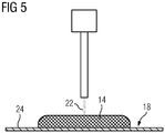
- FIG 5 shows a schematic representation of a method for producing at least one at least partially printed permanent magnet 14 on a base plate 24, the permanent magnet 14 being produced at least partially by means of cold gas spraying.
- solid particles 22 are sprayed directly onto the base plate 26, solid particles 22 made of a magnetic material being used.
- the solid particles 22 have, for example, iron, nickel, cobalt, samarium-cobalt, aluminum-nickel-cobalt, neodymium-iron-boron and / or samarium-iron-nickel.
- Solid particles 22 of at least two magnetic materials with different magnetic properties are optionally used.
- a hard magnetic material such as neodymium iron boron and a soft magnetic material such as iron.
- a cover 20 is arranged on the permanent magnet 14 and connected to the base plate 24. After the production of the at least one permanent magnet 14, it is magnetized.
- the further configuration of the permanent magnet 14 in FIG 5 corresponds to that in FIG 4 .
- FIG 6 shows a schematic representation of a second method for producing a rotor 6.
- solid particles 22 are sprayed directly onto the base plate 26, so that the permanent magnet 14 is connected directly to the base plate 26.
- a magnet module 26 is produced by spraying a cover 20 onto the permanent magnet 14 and the base plate 24 by means of cold gas spraying, so that the cover 20 is connected to both the permanent magnet 14 and the base plate 24.
- the at least one permanent magnet 14 is magnetized after the manufacture of the magnet module 26.
- the magnet module 26 is placed on a surface 16 of a rotor element 12 carrying a magnetic field, as in FIG FIG 3 shown, fixed with cold gas spraying.
- the rotor surface 16 is designed as a traverse surface, so that the flat base plate 26 lies flat on the rotor surface 16.
- FIG 7 shows a schematic representation of a third method for producing a rotor 6. Since the rotor 6 is designed as an external rotor, the rotor surface 6 is concave.
- the base plate 24 has a convex contact surface corresponding to the rotor surface 6, so that the base plate 24 can be connected to the rotor surface 6 in a planar manner.
- the base plate 24 has a cross section in the form of a segment of a circle.
- the rotor 6 is designed as an inner rotor, the rotor surface 6 being convex in the case of an inner rotor.
- the further design of the manufacturing process in FIG 7 corresponds to that in FIG 6 .
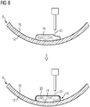
- FIG 8 shows a schematic representation of a fourth method for producing a rotor 6.
- at least one permanent magnet 14 is produced, at least partially, by means of cold gas spraying.
- solid particles 22 made of at least one magnetic material are sprayed directly onto the concave rotor surface 16 by means of cold gas spraying, so that the permanent magnet 14 is connected directly to the rotor element 12 of the rotor 6 carrying the magnetic field.
- a cover 20 is sprayed directly onto the permanent magnet 14 and the magnetic field-carrying rotor element 12 by means of cold gas spraying, so that the cover 20 is connected both to the permanent magnet 14 and to the magnetic field-carrying rotor element 12 of the rotor 6.
- the further design of the manufacturing process in FIG 8 corresponds to that in FIG 7 .
- FIG. 9 shows a schematic representation of a fifth method for producing a rotor 6.
- the connection is established by spraying the electrically conductive non-magnetic solid particles 22 by means of cold gas spraying in such a way that the cover 20 is connected to the rotor element 12 carrying the magnetic field
- the at least one permanent magnet 14 is then introduced in the axial direction between the cover 20 and the rotor surface 16.
- the further configuration of the rotor 6 in FIG. 9 corresponds to that in FIG 2 .
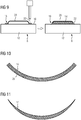
- FIG 10 shows a cross-sectional view of a first embodiment of a permanent magnet 14 which is designed as a shell magnet.
- the shell magnet is produced using an additive manufacturing method, in particular by means of cold gas spraying, and has a convex contact surface 28, which is designed to correspond to a concave rotor surface 16 of an external rotor, so that the shell magnet can be made contact with the rotor surface 16 of the external rotor.
- FIG 11 shows a cross-sectional view of a second embodiment of a permanent magnet 14, which is designed as a sickle magnet.
- the sickle magnet is produced using an additive manufacturing process, in particular using cold gas spraying, and its shape can also be used in a PM reluctance machine.
- FIG 12 shows a cross-sectional view of a third embodiment of a permanent magnet 14, which is produced using an additive manufacturing method, in particular by means of cold gas spraying, from materials with locally different magnetic properties, so that the permanent magnet 14, at least in cross section, has areas of different magnetic flux density B1, B2, B3.
- the permanent magnet 14 has a maximum in the middle magnetic flux density B1 as it decreases along the contact surface 28.
- the further configuration of the permanent magnet 14 in FIG 12 corresponds to that in FIG 2 .
- FIG. 13 shows a schematic representation of a first embodiment of an arrangement of permanent magnets 14 on a rotor surface 16.
- the permanent magnets 14 are produced using an additive manufacturing method, in particular by means of cold gas spraying, and are designed as arrow magnets.
- the arrow shape of the permanent magnets 14 is axially symmetrical in the axial direction A.
- the arrow magnets are alternately magnetized with essentially the same distances d1 in the circumferential direction U on the rotor surface 16.
- FIG 14 shows a schematic representation of a second embodiment of an arrangement of permanent magnets 14 on a rotor surface 16.
- the permanent magnets 14 are produced using an additive manufacturing method, in particular by means of cold gas spraying, and have a bevel in the axial direction A.
- the bevel is designed such that the permanent magnets 14 run in the axial direction parallel and at the same distance d1 from one another.
- the further configuration of the permanent magnets 14 in FIG 14 corresponds to that in FIG. 13 .
- FIG. 15 shows a schematic representation of a third embodiment of an arrangement of permanent magnets 14 on a rotor surface 16.
- the permanent magnets 14 have a pole offset.
- the permanent magnets 14 have different distances d1, d2 from one another in the circumferential direction U. As an example, the order of the distances d1, d2 is repeated periodically.
- the further configuration of the permanent magnets 14 in FIG. 15 corresponds to that in FIG 14 .
- FIG 16 shows a schematic representation of a wind turbine 30 with an electrical rotating machine 2.
- the wind turbine 30 there is an embodiment of an inventive electric rotating machine 2 for use.
- the electric rotating machine 2 used as a generator is driven directly (as a direct drive) or via a gear.
- the invention relates to a method for producing a rotor 6 for an electrical rotating machine 2 with a magnetic field-guiding, in particular eddy current-suppressing, rotor element 12 and at least one permanent magnet 14.
- a magnetic field-guiding, in particular eddy current-suppressing, rotor element 12 and at least one permanent magnet 14.
- the permanent magnet 14 be connected to the magnetic field-carrying rotor element 12 by means of an additive manufacturing method.
Landscapes
- Engineering & Computer Science (AREA)
- Power Engineering (AREA)
- Manufacturing & Machinery (AREA)
- Permanent Field Magnets Of Synchronous Machinery (AREA)
- Manufacture Of Motors, Generators (AREA)
Abstract
Die Erfindung betrifft ein Verfahren zur Herstellung eines Rotors (6) für eine elektrische rotierende Maschine (2) mit einem magnetfeldführenden, insbesondere wirbelstromunterdrückenden, Rotorelement (12) und mindestens einem Permanentmagneten (14). Um einen Rotor (6) anzugeben, der, im Vergleich zum Stand der Technik, einfacher und kostengünstiger herzustellen ist, wird vorgeschlagen, dass der Permanentmagnet (14) mittels eines additiven Fertigungsverfahrens mit dem magnetfeldführenden Rotorelement (12) verbunden wird.
Description
- Die Erfindung betrifft ein Verfahren zur Herstellung eines Rotors für eine elektrische rotierende Maschine mit einem magnetfeldführenden, insbesondere wirbelstromunterdrückenden, Rotorelement und mindestens einem Permanentmagneten.
- Die Erfindung betrifft darüber hinaus einen Rotor für eine elektrische rotierende Maschine, welcher mit einem derartigen Verfahren hergestellt ist.
- Ferner betrifft die Erfindung eine elektrische rotierende Maschine mit mindestens einem derartigen Rotor.
- Des Weiteren betrifft die Erfindung eine Windkraftanlage mit mindestens einer derartigen elektrischen rotierenden Maschine.
- Elektrische rotierende Maschinen sind beispielsweise als permanenterregte Synchronmaschinen, insbesondere als permanenterregte Drehstromsynchronmaschinen, ausgebildet. Derartige permanenterregte Drehstromsynchronmaschinen sind beispielsweise als Motor oder auch als Generator betreibbar. Ein Generator wird beispielsweise als Windgenerator in einer Windkraftanlage eingesetzt, wobei insbesondere Direct Drive Windgeneratoren einen Durchmesser von mehreren Metern aufweisen.
- Permanenterregte Synchronmaschinen weisen einen Rotor mit Permanentmagneten auf, welche mit einem magnetfeldführenden, insbesondere wirbelstromunterdrückenden, Rotorelement, beispielsweise einem Rotorblechpaket oder einem massiven Rotorjoch verbunden sind, um die Magnete während des Betriebes der elektrischen rotierenden Maschine zu sichern. Die Sicherung der Magnete, insbesondere bei sehr großen Maschinen, ist sehr aufwändig und teuer.
- Die Offenlegungsschrift
DE 10 2010 041 593 A1 beschreibt eine Magnetpolabdeckung für einen Pol eines Rotors einer elektrischen Maschine, welche eine erste Seitenlasche, eine zweite Seitenlasche, eine erste Seitenwand, eine zweite Seitenwand, eine Öffnung und einen zentralen Abdeckbereich zwischen der ersten Seitenwand und der zweiten Seitenwand aufweist. - Die Offenlegungsschrift
EP 2 587 633 A1 beschreibt ein Magnet-Abdeckblechmodul zum individuellen Positionieren und Schützen von Dauermagneten auf einem Rotorjoch für Windkraftanlagen. Das Magnetmodul weist eine Magnetabdeckplatte aus einem weichmagnetischen Werkstoff zum individuellen Abdecken der Dauermagnete auf, wobei eine nichtmagnetische Platte dauerhaft an der Magnetabdeckplatte befestigt ist. Die nichtmagnetische Platte weist Mittel zum Befestigen des Magnetabdeckplattenmoduls an einer Außenfläche des Rotorjochs auf, wobei die Befestigungsmittel abnehmbar sind, um eine separate Montage und Demontage des Abdeckplattenmoduls zu ermöglichen. Zusätzlich ist auf einer Innenfläche des Rotorjochs ein magnetischer Extender zur Führung des Magnetflusses und zur Vermeidung von Streuflüssen angeordnet. - Die Offenlegungsschrift
DE 10 2012 006 248 A1 beschreibt einen Kurzschlussläufer umfassend einen Kern, eine Vielzahl von Schlitzlöchern, die in dem Kern ausgebildet sind und sich entlang einer Drehachse des Kerns erstrecken, leitfähige Stangen, die in den Schlitzlöchern angeordnet sind und ein Paar leitfähiger Endringe, die an beiden Enden des Kerns angeordnet sind und miteinander mittels der leitfähigen Stangen verbunden sind. Zumindest eines aus den leitfähigen Stangen und dem Paar von leitfähigen Endringen ist durch ein Deckschichtmaterial aufgebaut, das durch Spritzen von Festkörperleiterpartikeln ausgebildet ist. - Die Offenlegungsschrift
EP 2 555 385 A1 beschreibt eine Permanentmagnetanordnung mit einer Grundplatte und mindestens einem Permanentmagneten, der an der Grundplatte befestigt ist. Der mindestens eine Permanentmagnet ist durch eine Kunststoffhaube abgedeckt. - Die Offenlegungsschrift
EP 1 844 181 A1 beschreibt ein Verfahren zum Beschichten eines Werkstückes mittels Kaltgasspritzen. Hierbei wird eine Kaltgas-Spritzdüse verwendet, die einen auf die Oberfläche gerichteten Teilchenstrahl erzeugt. - Der Erfindung liegt die Aufgabe zugrunde, ein Verfahren zur Herstellung eines Rotors für eine elektrische rotierende Maschine mit einem magnetfeldführenden, insbesondere wirbelstromunterdrückenden, Rotorelement und mindestens einem Permanentmagneten anzugeben, welches, im Vergleich zum Stand der Technik, einfacher und kostengünstiger ist.
- Die Aufgabe wird erfindungsgemäß durch ein Verfahren der eingangs genannten Art gelöst, wobei der Permanentmagnet mittels eines additiven Fertigungsverfahrens mit dem magnetfeldführenden Rotorelement verbunden wird.
- Ferner wird die Aufgabe erfindungsgemäß durch einen Rotor für eine elektrische rotierende Maschine gelöst, welcher mit einem derartigen Verfahren hergestellt ist.
- Darüber hinaus wird die Aufgabe erfindungsgemäß durch eine elektrische rotierende Maschine mit mindestens einem derartigen Rotor gelöst.
- Zudem wird die Aufgabe erfindungsgemäß durch eine Windkraftanlage mit mindestens einer derartigen elektrischen rotierenden Maschine gelöst.
- Die in Bezug auf das Verfahren nachstehend angeführten Vorteile und bevorzugten Ausgestaltungen lassen sich sinngemäß auf den Rotor, die elektrische rotierende Maschine und die Windkraftanlage übertragen.
- Der Erfindung liegt die Überlegung zugrunde, die Herstellung eines Rotors durch die Befestigung mindestens eines Permanentmagneten mit Hilfe eines additiven Fertigungsverfahrens zu vereinfachen. Derartige additive Fertigungsverfahren sind beispielsweise Pulverbettverfahren wie selektives Laserschmelzen oder selektives Lasersintern, Freiraumverfahren wie Auftragschweißen, Flüssigmaterialverfahren wie Stereolithografie, oder andere Schichtaufbauverfahren wie 3D-Siebdruck. Der mindestens eine Permanentmagnet wird auf einem magnetfeldführenden Rotorelement mit Hilfe des additiven Fertigungsverfahrens befestigt, um die Permanentmagnete während des Betriebes zu sichern, wobei das magnetfeldführende Rotorelement aus einem weichmagnetischen Werkstoff, insbesondere aus Stahl, gefertigt und als Blechpaket oder als massives Rotorjoch ausgeführt ist. Durch die Befestigung der Permanentmagnete mit Hilfe eines additiven Fertigungsverfahrens wird die Bearbeitung der Rotoroberfläche vereinfacht und die Anzahl von Prozessschritten zur Herstellung des Rotors reduziert, wodurch Kosten eingespart werden.
- Bei einer vorteilhaften Ausgestaltung wird der mindestens eine Permanentmagnet vor der Verbindung mit dem magnetfeldführenden Rotorelement magnetisiert. Eine Magnetisierung des Permanentmagneten vor der Verbindung mit dem magnetfeldführenden Rotorelement vereinfacht die Fertigung des Rotors.
- In einer bevorzugten Ausführungsform wird der Permanentmagnet mittels Kaltgasspritzen mit dem magnetfeldführenden Rotorelement verbunden. Mit Hilfe von Kaltgasspritzen sind, im Vergleich zu anderen additiven Fertigungsverfahren, dicke Schichten, beispielsweise im Millimeterbereich und im Zentimeterbereich, in kurzer Zeit und geometrisch sehr flexibel herstellbar. Da das mittels Kaltgasspritzen aufgetragene Material nicht geschmolzen, sondern durch seine kinetische Energie verformt wird und dadurch eine dichte und fest haftende Schicht bildet, sind der Permanentmagnet und das magnetfeldführende Rotorelement nur geringen Temperaturbelastungen ausgesetzt. Darüber hinaus werden thermisch induzierte Spannungen, insbesondere im Bereich der Verbindung, weitestgehend vermieden.
- Besonders vorteilhaft wird der Permanentmagnet über Verbindungsmittel mit dem magnetfeldführenden Rotorelement verbunden, wobei die Verbindungsmittel, insbesondere elektrisch leitfähige, Festkörperpartikel umfassen, welche mittels Kaltgasspritzen zur Verbindung des Permanentmagneten mit dem magnetfeldführenden Rotorelement aufgesprüht werden. Die Verbindungsmittel stellen auf einfache Weise, durch Bildung einer dichten und fest haftenden Schicht, eine stabile Verbindung zwischen dem Permanentmagneten und dem magnetfeldführenden Rotorelement her. Das Kaltgasspritzen bietet eine große Flexibilität hinsichtlich der Form, der Dicke und des Materials.
- Bei einer weiteren vorteilhaften Ausgestaltung werden die Festkörperpartikel der Verbindungsmittel aus einem unmagnetischen metallischen Werkstoff, insbesondere aus einem Edelstahl, hergestellt. Durch die Verwendung unmagnetischer Festkörperpartikel wird die Herstellung der Verbindung, insbesondere bei einem magnetisierten Permanentmagneten, vereinfacht. Ferner sind unmagnetische Festkörperpartikel für die Flussführung in der Maschine vorteilhaft, sodass beispielsweise Streuflüsse zumindest minimiert werden.
- In einer bevorzugten Ausführungsform umfassen die Verbindungsmittel eine Abdeckung, von der der Permanentmagnet zumindest teilweise bedeckt wird. Durch die Abdeckung wird der Permanentmagnet, insbesondere in Radialrichtung, gesichert. Ferner wird der Permanentmagnet durch die Abdeckung vor äußeren Einflüssen geschützt.
- Besonders vorteilhaft wird die Abdeckung aus einem unmagnetischen metallischen Werkstoff, insbesondere aus Edelstahl, hergestellt. Durch die Verwendung eines unmagnetischen metallischen Werkstoffs wird die Montage der Abdeckung, insbesondere bei einem magnetisierten Permanentmagneten, vereinfacht. Bei einer weiteren vorteilhaften Ausgestaltung ist die Abdeckung aus Festkörperpartikeln aufgebaut, welche mittels Kaltgasspritzen aufgesprüht werden. Durch das Aufsprühen der Abdeckung wird der Permanentmagnet auf einfache und kostengünstige Weise geschützt, da beispielsweise ein Vergießen des Permanentmagneten in der Abdeckung entfällt. Durch das Kaltgasspritzen ergibt sich eine große Flexibilität, beispielsweise hinsichtlich einer Materialstärke und Form der Abdeckung.
- In einer weiteren vorteilhaften Ausführungsform werden die Festkörperpartikel der Abdeckung direkt auf den Permanentmagneten aufgesprüht. Durch das direkte Aufsprühen der Festkörperpartikel wird die Fertigung des Rotors zusätzlich vereinfacht.
- Bei einer weiteren vorteilhaften Ausgestaltung umfassen die Verbindungsmittel eine Grundplatte, welche zwischen dem Permanentmagneten und dem magnetfeldführenden Rotorelement angeordnet wird. Mit Hilfe der Grundplatte ist beispielsweise ein Magnetmodul mit einer Abdeckung und einer Grundplatte mit sehr wenigen Prozessschritten automatisiert herstellbar, wodurch Kosten eingespart werden.
- Besonders vorteilhaft wird die Abdeckung mit der Grundplatte mittels Kaltgasspritzen verbunden. Da das mittels Kaltgasspritzen aufgetragene Material nicht geschmolzen, sondern durch seine kinetische Energie verformt wird, sind der Permanentmagnet und die Grundplatte nur geringen Temperaturbelastungen ausgesetzt.
- In einer weiteren vorteilhaften Ausführungsform wird die Grundplatte mit dem magnetfeldführenden Rotorelement mittels Kaltgasspritzen verbunden. Da das mittels Kaltgasspritzen aufgetragene Material nicht geschmolzen, sondern durch seine kinetische Energie verformt wird, werden thermisch induzierte Spannungen, insbesondere im Bereich der Verbindung, weitestgehend vermieden.
- Bei einer weiteren vorteilhaften Ausgestaltung wird der mindestens eine Permanentmagnet zumindest teilweise mittels Kaltgasspritzen hergestellt. Beispielsweise wird der Permanentmagnet direkt auf ein Rotorjoch aufgesprüht, sodass keine zusätzliche Abdeckung zur Fixierung des Permanentmagneten erforderlich ist. Somit wird die Anzahl der Prozessschritte zur Herstellung des Rotors reduziert und es werden Kosten eingespart.
- Besonders vorteilhaft werden bei der Herstellung des mindestens einen Permanentmagneten mindestens zwei magnetische Werkstoffe mit unterschiedlichen magnetischen Eigenschaften verwendet. Werkstoffe mit unterschiedlichen magnetischen Eigenschaften sind beispielsweise ein hartmagnetischer Werkstoff und ein weichmagnetischer Werkstoff. Beispielsweise sind Permanentmagnete mit lokal unterschiedlichen magnetischen Eigenschaften herstellbar, sodass ein Permanentmagnet Bereiche unterschiedlicher magnetische Flussdichte aufweist wodurch eine Verbesserung der Feldhomogenität, insbesondere im Luftspalt, erreicht wird.
- In einer weiteren vorteilhaften Ausführungsform wird eine Form des mindestens einen Permanentmagneten derartig gewählt, dass ein Oberwellenmoment zumindest reduziert wird. Beispielsweise werden Ecken eines quaderförmigen Permanentmagneten abgerundet, um das Oberwellenmoment zumindest zu reduzieren. Durch eine Anpassung der Form des Permanentmagneten wird eine Verbesserung der elektrischen Eigenschaften des Rotors einfach und kostengünstig ermöglicht.
- Im Folgenden wird die Erfindung anhand der in den Figuren dargestellten Ausführungsbeispiele näher beschrieben und erläutert.
- Es zeigen:
- FIG 1
- eine dreidimensionale Schnittdarstellung einer elektrischen rotierenden Maschine,
- FIG 2
- eine dreidimensionale Schnittdarstellung des Rotors der elektrischen rotierenden Maschine,
- FIG 3
- eine schematische Darstellung eines ersten Verfahrens zur Herstellung eines Rotors,
- FIG 4
- eine schematische Darstellung eines Verfahrens zur Herstellung eines Magnetmoduls,
- FIG 5
- eine schematische Darstellung eines Verfahrens zur Herstellung mindestens eines zumindest teilweise gedruckten Permanentmagneten auf einer Grundplatte,
- FIG 6
- eine schematische Darstellung eines zweiten Verfahrens zur Herstellung eines Rotors,
- FIG 7
- eine schematische Darstellung eines dritten Verfahrens zur Herstellung eines Rotors,
- FIG 8
- eine schematische Darstellung eines vierten Verfahrens zur Herstellung eines Rotors,
- FIG 9
- eine schematische Darstellung eines fünften Verfahrens zur Herstellung eines Rotors,
- FIG 10
- eine Querschnittdarstellung einer ersten Ausführungsform eines Permanentmagneten,
- FIG 11
- eine Querschnittdarstellung einer zweiten Ausführungsform eines Permanentmagneten,
- FIG 12
- eine Querschnittdarstellung einer dritten Ausführungsform eines Permanentmagneten,
- FIG 13
- eine schematische Darstellung einer ersten Ausführungsform einer Anordnung von Permanentmagneten auf einer Rotoroberfläche,
- FIG 14
- eine schematische Darstellung einer zweiten Ausführungsform einer Anordnung von Permanentmagneten auf einer Rotoroberfläche,
- FIG 15
- eine schematische Darstellung einer dritten Ausführungsform einer Anordnung von Permanentmagneten auf einer Rotoroberfläche und
- FIG 16
- eine schematische Darstellung eines Windkraftrades mit einer elektrischen rotierenden Maschine.
- Bei den im Folgenden erläuterten Ausführungsbeispielen handelt es sich um bevorzugte Ausführungsformen der Erfindung. Bei den Ausführungsbeispielen stellen die beschriebenen Komponenten der Ausführungsformen jeweils einzelne, unabhängig voneinander zu betrachtende Merkmale der Erfindung dar, welche die Erfindung jeweils auch unabhängig voneinander weiterbilden und damit auch einzeln oder in einer anderen als der gezeigten Kombination als Bestandteil der Erfindung anzusehen sind. Des Weiteren sind die beschriebenen Ausführungsformen auch durch weitere der bereits beschriebenen Merkmale der Erfindung ergänzbar.
- Gleiche Bezugszeichen haben in den verschiedenen Figuren die gleiche Bedeutung.
-
FIG 1 zeigt eine dreidimensionale Schnittdarstellung einer elektrischen rotierenden Maschine 2. Die elektrische rotierende Maschine 2 ist als permanenterregte Synchronmaschine ausgeführt und umfasst einen um eine Rotationsachse 4 rotierbaren Rotor 6. Die Rotationsachse 4 definiert eine Axialrichtung, eine Radialrichtung und eine Umfangsrichtung. Der Rotor 6 ist exemplarisch als Außenläufer ausgeführt und umfasst Permanentmagnete, welche aus Gründen der Übersichtlichkeit inFIG 1 nicht dargestellt sind. Darüber hinaus weist die elektrische rotierende Maschine 2 einen Stator 8 auf, welcher innerhalb des als Außenläufer ausgeführten Rotors 6 angeordnet ist. Zwischen dem Rotor 6 und dem Stator 8 ist ein Spalt 10, der insbesondere als Luftspalt ausgeführt ist, ausgebildet. Der Rotor 6 ist über ein Lager 11, welches inFIG 1 schematisch dargestellt ist, gelagert. -
FIG 2 zeigt eine dreidimensionale Schnittdarstellung des Rotors 6 der elektrischen rotierenden Maschine 2. Der Rotor 8 umfasst ein magnetfeldführendes, insbesondere wirbelstromunterdrückendes, Rotorelement 12 und Permanentmagnete 14. Das magnetfeldführende, insbesondere wirbelstromunterdrückende, Rotorelement 12 ist beispielsweise als massives Rotorjoch ausgeführt, welches aus einem weichmagnetischen Werkstoff, insbesondere aus Stahl, gefertigt ist. Alternativ ist das magnetfeldführende, insbesondere wirbelstromunterdrückende, Rotorelement 12 als Blechpaket ausgeführt. Das Blechpaket ist beispielsweise aus einer Vielzahl von gestapelten Elektroblechen aufgebaut. Die Permanentmagnete 14 sind in Umfangsrichtung auf einer zumindest teilweise konkav ausgeführten Rotoroberfläche 16 angeordnet. Alternativ ist die Rotoroberfläche 16 als Polygonzugoberfläche ausgeführt. Eine Polygonzugoberfläche weist im Querschnitt die Form eines N-Ecks auf, wobei die Permanentmagnete auf ebenen Abschnitten der Polygonzugoberfläche angeordnet sind. Beispielsweise entspricht N einer Polzahl der elektrischen rotierenden Maschine 2. Optional sind jeweils mindestens zwei Permanentmagnete 14 in Axialrichtung hintereinander angeordnet. - Die Permanentmagnete 14 sind mit dem magnetfeldführenden Rotorelement 12 über Verbindungsmittel 18 verbunden. Die Verbindungsmittel 18 umfassen zumindest eine Abdeckung 20 und einen Verbindungswerkstoff, durch welchen die Permanentmagnete 14 mittels eines additiven Fertigungsverfahrens mit dem magnetfeldführenden Rotorelement 12 verbunden werden. Additive Fertigungsverfahren sind beispielsweise Pulverbettverfahren wie selektives Laserschmelzen oder selektives Lasersintern, Freiraumverfahren wie Auftragschweißen oder Kaltgasspritzen, Flüssigmaterialverfahren wie Stereolithografie oder andere Schichtaufbauverfahren wie 3D-Siebdruck. Beispielswiese werden als Verbindungswerkstoff elektrisch leitfähige unmagnetische Festkörperpartikel 22 verwendet, welche mit Hilfe von Kaltgasspritzen, auf Englisch Coldspray, aufgesprüht werden. Unmagnetische Festkörperpartikel sind für die Flussführung in der elektrischen rotierenden Maschine 2 vorteilhaft, sodass beispielsweise Streuflüsse zumindest minimiert werden. Durch die mittels Kaltgasspritzen aufgetragenen Festkörperpartikel 22 wird die Abdeckung 20, welche im Wesentlichen der Form der Permanentmagnete 14 angepasst ist, mit dem magnetfeldführenden Rotorelement 12 verbunden, sodass die Permanentmagnete 14 fixiert und damit gesichert sind. Eine Form der Permanentmagnete 14 wird derartig gewählt, dass ein Oberwellenmoment zumindest reduziert wird. Ein Oberwellenmoment wird beispielsweise reduziert, indem Ecken eines insbesondere quaderförmigen Permanentmagneten 14 abgerundet werden.
- Die Abdeckung 20 wird aus einem unmagnetischen metallischen Werkstoff, insbesondere aus Edelstahl, hergestellt. Darüber hinaus sind die Permanentmagnete 14 in Axialrichtung, beispielsweise formschlüssig, gesichert, was aus Gründen der Übersichtlichkeit nicht in
FIG 2 dargestellt ist. Optional sind die Permanentmagnete 14 unter der Abdeckung 20 vergossen. Die weitere Ausgestaltung des Rotors 6 inFIG 2 entspricht der inFIG 1 . -
FIG 3 zeigt eine schematische Darstellung eines ersten Verfahrens zur Herstellung eines Rotors 6. Mindestens ein Permanentmagnet 14 wird mit Hilfe von Verbindungsmitteln 18 mit einem magnetfeldführenden Rotorelement 12 verbunden, wobei die Verbindungsmittel 18 eine Abdeckung 20 und eine Grundplatte 24 umfassen. Die Abdeckung 20 und die Grundplatte 24 umschließen den Permanentmagnet 14 zumindest teilweise und bilden ein Magnetmodul 26, wobei die Abdeckung 20 mit der Grundplatte 24 über eine stoffschlüssige Verbindung, insbesondere über eine Schweißverbindung und/oder über Verbindungselemente, insbesondere Schrauben und/oder Nieten, verbunden ist. Die Grundplatte 24 ist aus einem, insbesondere magnetfeldführenden, metallischen Werkstoff hergestellt und weist ebene Auflageflächen auf. Die Verbindungsmittel 18 umfassen darüber hinaus elektrisch leitfähige unmagnetische Festkörperpartikel 22, welche mittels Kaltgasspritzen aufgesprüht werden. Die Festkörperpartikel 22 werden mittels Kaltgasspritzen derartig aufgesprüht, dass das Magnetmodul 26 auf dem magnetfeldführenden Rotorelement 12 fixiert und damit gesichert wird. Der mindestens eine Permanentmagnet 14 wird vor der Verbindung mit dem magnetfeldführenden Rotorelement 12, beispielsweise nach der Herstellung des Magnetmoduls 26, magnetisiert. Die weitere Ausgestaltung des Rotors 6 inFIG 3 entspricht der inFIG 2 . -
FIG 4 zeigt eine schematische Darstellung eines Verfahrens zur Herstellung eines Magnetmoduls 26. Mindestens ein Permanentmagnet 14 wird auf eine Grundplatte 24 aufgelegt. Daraufhin werden Festkörperpartikel 22 mittels Kaltgasspritzen direkt auf den Permanentmagnet 14 und die Grundplatte 24 aufgesprüht, sodass die Festkörperpartikel 22 eine Abdeckung 20 bilden, von der der Permanentmagnet (14) zumindest teilweise bedeckt wird, und die Abdeckung 20 den Permanentmagnet 14 auf der Grundplatte 24 fixiert. Die Festkörperpartikel 22 sind aus einem unmagnetischen metallischen Werkstoff, insbesondere aus Edelstahl, hergestellt. Nach dem Fixieren des mindestens einen Permanentmagneten 14 wird dieser magnetisiert. Die weitere Ausgestaltung des Magnetmoduls 26 inFIG 4 entspricht der inFIG 3 . -
FIG 5 zeigt eine schematische Darstellung eines Verfahrens zur Herstellung mindestens eines zumindest teilweise gedruckten Permanentmagneten 14 auf einer Grundplatte 24, wobei der Permanentmagnet 14 zumindest teilweise mittels Kaltgasspritzen hergestellt wird. Bei der Herstellung des Permanentmagneten 14 mittels Kaltgasspritzen werden Festkörperpartikel 22 direkt auf die Grundplatte 26 gesprüht, wobei Festkörperpartikel 22 aus einem magnetischen Werkstoff verwendet werden. Die Festkörperpartikel 22 weisen beispielsweise Eisen, Nickel, Kobalt, Samarium-Kobalt, Aluminium-Nickel-Kobalt, Neodym-Eisen-Bor und/oder Samarium-Eisen-Nickel auf. Optional werden Festkörperpartikel 22 aus mindestens zwei magnetischen Werkstoffen mit unterschiedlichen magnetischen Eigenschaften verwendet. Werkstoffe mit unterschiedlichen magnetischen Eigenschaften sind beispielsweise ein hartmagnetischer Werkstoff wie Neodym-Eisen-Bor und ein weichmagnetischer Werkstoff wie Eisen. Optional wird in einem weiteren Schritt, beispielsweise mittels Kaltgasspritzen, eine Abdeckung 20 auf dem Permanentmagnet 14 angeordnet und mit der Grundplatte 24 verbunden. Nach der Herstellung des mindestens einen Permanentmagneten 14 wird dieser magnetisiert. Die weitere Ausgestaltung des Permanentmagneten 14 inFIG 5 entspricht der inFIG 4 . -
FIG 6 zeigt eine schematische Darstellung eines zweiten Verfahrens zur Herstellung eines Rotors 6. Zunächst wird, wie inFIG 5 gezeigt, mindestens ein Permanentmagnet 14 auf einer Grundplatte 26, zumindest teilweise, mittels Kaltgasspritzen hergestellt. Insbesondere werden Festkörperpartikel 22 direkt auf die Grundplatte 26 gesprüht, sodass der Permanentmagnet 14 direkt mit der Grundplatte 26 verbunden ist. - In einem weiteren Schritt wird, wie in
FIG 4 gezeigt, ein Magnetmodul 26 hergestellt, indem eine Abdeckung 20 mittels Kaltgasspritzen auf den Permanentmagnet 14 und die Grundplatte 24 aufgesprüht wird, sodass die Abdeckung 20 sowohl mit dem Permanentmagneten 14 als auch mit der Grundplatte 24 verbunden ist. Der mindestens eine Permanentmagnet 14 wird nach der Herstellung des Magnetmoduls 26 magnetisiert. - In einem weiteren Schritt wird das Magnetmodul 26 auf einer Oberfläche 16 eines magnetfeldführenden Rotorelements 12 eines Rotors 6, wie in
FIG 3 gezeigt, mittels Kaltgasspritzen fixiert. Die Rotoroberfläche 16 ist als Polygonzugoberfläche ausgeführt, sodass die ebene Grundplatte 26 flächig auf der Rotoroberfläche 16 aufliegt. -
FIG 7 zeigt eine schematische Darstellung eines dritten Verfahrens zur Herstellung eines Rotors 6. Da der Rotor 6 als Außenläufer ausgestaltet ist, ist die Rotoroberfläche 6 konkav ausgeführt. Die Grundplatte 24 weist eine zur Rotoroberfläche 6 korrespondierende konvexe Auflagefläche auf, sodass die Grundplatte 24 flächig mit der Rotoroberfläche 6 verbindbar ist. Insbesondere weist die Grundplatte 24 einen kreissegmentförmigen Querschnitt auf. - Alternativ ist der Rotor 6 als Innenläufer ausgeführt, wobei bei einem Innenläufer die Rotoroberfläche 6 konvex ausgeführt ist. Eine dazu korrespondierende Grundplatte 24 für einen Innenläufer, welche in
FIG 7 nicht dargestellt ist, weist entsprechend eine konkave Auflagefläche auf, sodass die Grundplatte 24 flächig mit der Rotoroberfläche 6 verbindbar ist. Die weitere Ausgestaltung des Herstellungsverfahrens inFIG 7 entspricht dem inFIG 6 . -
FIG 8 zeigt eine schematische Darstellung eines vierten Verfahrens zur Herstellung eines Rotors 6. Zunächst wird mindestens ein Permanentmagnet 14, zumindest teilweise, mittels Kaltgasspritzen hergestellt. Insbesondere werden Festkörperpartikel 22 aus mindestens einem magnetischen Werkstoff mittels Kaltgasspritzen direkt auf die konkave Rotoroberfläche 16 gesprüht, sodass der Permanentmagnet 14 direkt mit dem magnetfeldführenden Rotorelement 12 des Rotors 6 verbunden ist. - In einem weiteren Schritt wird eine Abdeckung 20 mittels Kaltgasspritzen direkt auf den Permanentmagneten 14 und das magnetfeldführende Rotorelement 12 gesprüht, sodass die Abdeckung 20 sowohl mit dem Permanentmagneten 14 als auch mit dem magnetfeldführenden Rotorelement 12 des Rotors 6 verbunden ist. Die weitere Ausgestaltung des Herstellungsverfahrens in
FIG 8 entspricht dem inFIG 7 . -
FIG 9 zeigt eine schematische Darstellung eines fünften Verfahrens zur Herstellung eines Rotors 6. Zunächst werden Verbindungsmittel 18 für mindestens einen Permanentmagneten 14, welche eine Abdeckung 20 und Festkörperpartikel 22 umfassen, mit der ebenen Rotoroberfläche 16 verbunden. Die Verbindung wird hergestellt, indem die elektrisch leitfähigen unmagnetischen Festkörperpartikel 22 mittels Kaltgasspritzen derartig aufgesprüht werden, dass die Abdeckung 20 mit dem magnetfeldführenden Rotorelement 12 verbunden ist - Daraufhin wird der mindestens eine Permanentmagnet 14 in Axialrichtung zwischen der Abdeckung 20 und der Rotoroberfläche 16 eingeführt. Die weitere Ausgestaltung des Rotors 6 in
FIG 9 entspricht der inFIG 2 . -
FIG 10 zeigt eine Querschnittdarstellung einer ersten Ausführungsform eines Permanentmagneten 14 welcher als Schalenmagnet ausgeführt ist. Der Schalenmagnet ist mit einem additiven Fertigungsverfahren, insbesondere mittels Kaltgasspritzen, hergestellt und weist eine konvexe Kontaktfläche 28 auf, welche korrespondierend zu einer konkaven Rotoroberfläche 16 eines Außenläufers ausgeführt ist, sodass der Schalenmagnet flächig mit der Rotoroberfläche 16 des Außenläufers kontaktierbar ist. -
FIG 11 zeigt eine Querschnittdarstellung einer zweiten Ausführungsform eines Permanentmagneten 14, welcher als Sichelmagnet ausgeführt ist. Der Sichelmagnet ist mit einem additiven Fertigungsverfahren, insbesondere mittels Kaltgasspritzen, hergestellt und ist durch seine Form auch in einer PM-Reluktanzmaschine verwendbar. -
FIG 12 zeigt eine Querschnittdarstellung einer dritten Ausführungsform eines Permanentmagneten 14, welcher mit einem additiven Fertigungsverfahren, insbesondere mittels Kaltgasspritzen, aus Werkstoffen mit lokal unterschiedlichen magnetischen Eigenschaften hergestellt ist, sodass der Permanentmagnet 14, zumindest im Querschnitt, Bereiche unterschiedlicher magnetischer Flussdichte B1, B2, B3 aufweist. Beispielsweise weist der Permanentmagnet 14 in der Mitte eine maximale magnetische Flussdichte B1 auf, während diese entlang der Kontaktfläche 28 abnimmt. Die weitere Ausgestaltung des Permanentmagneten 14 inFIG 12 entspricht der inFIG 2 . -
FIG 13 zeigt eine schematische Darstellung einer ersten Ausführungsform einer Anordnung von Permanentmagneten 14 auf einer Rotoroberfläche 16. Die Permanentmagnete 14 sind mit einem additiven Fertigungsverfahren, insbesondere mittels Kaltgasspritzen, hergestellt und als Pfeilmagnete ausgeführt. Die Pfeilform der Permanentmagnete 14 ist in Axialrichtung A achsensymmetrisch ausgebildet. Ferner sind die Pfeilmagnete wechselnd magnetisiert mit im Wesentlichen gleichen Abständen d1 in Umfangsrichtung U auf der Rotoroberfläche 16 angeordnet. -
FIG 14 zeigt eine schematische Darstellung einer zweiten Ausführungsform einer Anordnung von Permanentmagneten 14 auf einer Rotoroberfläche 16. Die Permanentmagnete 14 sind mit einem additiven Fertigungsverfahren, insbesondere mittels Kaltgasspritzen, hergestellt und weisen in Axialrichtung A eine Schrägung auf. Die Schrägung ist so ausgeführt, dass die Permanentmagnete 14 in Axialrichtung parallel und mit gleichem Abstand d1 zueinander verlaufen. Die weitere Ausgestaltung der Permanentmagnete 14 inFIG 14 entspricht der inFIG 13 . -
FIG 15 zeigt eine schematische Darstellung einer dritten Ausführungsform einer Anordnung von Permanentmagneten 14 auf einer Rotoroberfläche 16. Zusätzlich zu einer Schrägung weisen die Permanentmagnete 14 einen Polversatz auf. Die Permanentmagnete 14 weisen in Umfangsrichtung U unterschiedliche Abstände d1, d2 zueinander auf. Beispielhaft wiederholt sich die Reihenfolge der Abstände d1, d2 periodisch. Die weitere Ausgestaltung der Permanentmagnete 14 inFIG 15 entspricht der inFIG 14 . -
FIG 16 zeigt eine schematische Darstellung einer Windkraftanlage 30 mit einer elektrischen rotierenden Maschine 2. In der Windkraftanlage 30 kommt eine Ausführungsform einer erfindungsgemäßen elektrischen rotierenden Maschine 2 zum Einsatz. Die als Generator eingesetzte elektrische rotierende Maschine 2 wird direkt (als Direktantrieb) oder über ein Getriebe angetrieben. - Zusammenfassend betrifft die Erfindung ein Verfahren zur Herstellung eines Rotors 6 für eine elektrische rotierende Maschine 2 mit einem magnetfeldführenden, insbesondere wirbelstromunterdrückenden, Rotorelement 12 und mindestens einem Permanentmagneten 14. Um einen Rotor 6 anzugeben, der, im Vergleich zum Stand der Technik, einfacher und kostengünstiger herzustellen ist, wird vorgeschlagen, dass der Permanentmagnet 14 mittels eines additiven Fertigungsverfahrens mit dem magnetfeldführenden Rotorelement 12 verbunden wird.
Claims (19)
- Verfahren zur Herstellung eines Rotors (6) für eine elektrische rotierende Maschine (2) mit einem magnetfeldführenden, insbesondere wirbelstromunterdrückenden, Rotorelement (12) und mindestens einem Permanentmagneten (14),
dadurch gekennzeichnet, dass der Permanentmagnet (14) mittels eines additiven Fertigungsverfahrens mit dem magnetfeldführenden Rotorelement (12) verbunden wird. - Verfahren nach Anspruch 1,
wobei der mindestens eine Permanentmagnet (14) vor der Verbindung mit dem magnetfeldführenden Rotorelement (12) magnetisiert wird. - Verfahren nach einem der Ansprüche 1 oder 2,
der Permanentmagnet (14) mittels Kaltgasspritzen mit dem magnetfeldführenden Rotorelement (12) verbunden wird. - Verfahren nach Anspruch 3,
wobei der Permanentmagnet (14) über Verbindungsmittel (18) mit dem magnetfeldführenden Rotorelement (12) verbunden wird, wobei die Verbindungsmittel (18), insbesondere elektrisch leitfähige, Festkörperpartikel (22) umfassen, welche mittels Kaltgasspritzen zur Verbindung des Permanentmagneten (14) mit dem magnetfeldführenden Rotorelement (12) aufgesprüht werden. - Verfahren nach Anspruch 4,
wobei die Festkörperpartikel (22) der Verbindungsmittel (20) aus einem unmagnetischen metallischen Werkstoff, insbesondere aus einem Edelstahl, hergestellt werden. - Verfahren nach einem der Ansprüche 4 oder 5,
wobei die Verbindungsmittel (18) eine Abdeckung (20) umfassen von der der Permanentmagnet (14) zumindest teilweise bedeckt wird. - Verfahren nach Anspruch 6,
wobei die Abdeckung (20) aus einem unmagnetischen metallischen Werkstoff, insbesondere aus Edelstahl, hergestellt wird. - Verfahren nach einem der Ansprüche 6 oder 7,
wobei die Abdeckung (20) aus Festkörperpartikeln (22) aufgebaut ist, welche mittels Kaltgasspritzen aufgesprüht werden. - Verfahren nach Anspruch 8,
wobei die Festkörperpartikel (22) der Abdeckung (20) direkt auf den Permanentmagneten (14) aufgesprüht werden. - Verfahren nach einem der Ansprüche 4 bis 9,
wobei die Verbindungsmittel (18) eine Grundplatte (24) umfassen, welche zwischen dem Permanentmagneten (14) und dem magnetfeldführenden Rotorelement (12) angeordnet wird. - Verfahren nach einem der Ansprüche 6 bis 9 und
Anspruch 10,
wobei die Abdeckung (20) mit der Grundplatte (24) mittels Kaltgasspritzen verbunden wird. - Verfahren nach einem der Ansprüche 10 oder 11,
wobei die Grundplatte (24) mit dem magnetfeldführenden Rotorelement (12) mittels Kaltgasspritzen verbunden wird. - Verfahren nach einem der vorherigen Ansprüche,
wobei der mindestens eine Permanentmagnet (14) zumindest teilweise mittels Kaltgasspritzen hergestellt wird. - Verfahren nach Anspruch 13,
wobei bei der Herstellung des mindestens einen Permanentmagneten (14) mindestens zwei magnetische Werkstoffe mit unterschiedlichen magnetischen Eigenschaften verwendet werden. - Verfahren nach einem der vorherigen Ansprüche,
wobei eine Form des mindestens einen Permanentmagneten (14) derartig gewählt wird, dass ein Oberwellenmoment zumindest reduziert wird. - Rotor (6) für eine elektrische rotierende Maschine (2), welcher mit einem Verfahren nach einem der Ansprüche 1 bis 15 hergestellt ist.
- Rotor (6) nach Anspruch 16,
wobei der Rotor (6) als Außenläufer ausgeführt ist. - Elektrische rotierende Maschine (2) mit mindestens einem Rotor (6) nach einem der Ansprüche 16 oder 17.
- Windkraftanlage (30) mit mindestens einer elektrischen rotierenden Maschine (2) nach Anspruch 18.
Priority Applications (2)
| Application Number | Priority Date | Filing Date | Title |
|---|---|---|---|
| EP18197408.0A EP3629454A1 (de) | 2018-09-28 | 2018-09-28 | Verfahren zur herstellung eines rotors für eine elektrische rotierende maschine |
| PCT/EP2019/074812 WO2020064418A1 (de) | 2018-09-28 | 2019-09-17 | Verfahren zur herstellung eines rotors für eine elektrische rotierende maschine |
Applications Claiming Priority (1)
| Application Number | Priority Date | Filing Date | Title |
|---|---|---|---|
| EP18197408.0A EP3629454A1 (de) | 2018-09-28 | 2018-09-28 | Verfahren zur herstellung eines rotors für eine elektrische rotierende maschine |
Publications (1)
| Publication Number | Publication Date |
|---|---|
| EP3629454A1 true EP3629454A1 (de) | 2020-04-01 |
Family
ID=63708186
Family Applications (1)
| Application Number | Title | Priority Date | Filing Date |
|---|---|---|---|
| EP18197408.0A Withdrawn EP3629454A1 (de) | 2018-09-28 | 2018-09-28 | Verfahren zur herstellung eines rotors für eine elektrische rotierende maschine |
Country Status (2)
| Country | Link |
|---|---|
| EP (1) | EP3629454A1 (de) |
| WO (1) | WO2020064418A1 (de) |
Cited By (4)
| Publication number | Priority date | Publication date | Assignee | Title |
|---|---|---|---|---|
| EP4191836A3 (de) * | 2021-12-03 | 2024-01-03 | Hamilton Sundstrand Corporation | Additive herstellung eines pumpenlaufrads mit rotor eines elektromotors |
| US12117016B2 (en) | 2021-12-03 | 2024-10-15 | Hamilton Sundstrand Corporation | Shaftless rotary machine |
| DE102024120493A1 (de) * | 2024-07-19 | 2026-01-22 | Bayerische Motoren Werke Aktiengesellschaft | Rotor für eine elektrische maschine |
| DE102024120492A1 (de) * | 2024-07-19 | 2026-01-22 | Bayerische Motoren Werke Aktiengesellschaft | Rotor für eine elektrische maschine |
Citations (9)
| Publication number | Priority date | Publication date | Assignee | Title |
|---|---|---|---|---|
| EP1263006A2 (de) * | 2001-05-30 | 2002-12-04 | Ford Motor Company | Verfahren zur Dauermagnetherstellung durch kinetisches Versprühen und elektromagnetisches Gerät daraus |
| EP1844181A1 (de) | 2005-02-02 | 2007-10-17 | Siemens Aktiengesellschaft | Verfahren zum kaltgasspritzen |
| DE102010041593A1 (de) | 2010-09-29 | 2012-03-29 | Siemens Aktiengesellschaft | Magnetpolabdeckung einer elektrischen Maschine |
| DE102012006248A1 (de) | 2011-04-04 | 2012-10-04 | Fanuc Corporation | Kurzschlussläufer und dessen Herstellungsverfahren |
| EP2555385A1 (de) | 2011-08-01 | 2013-02-06 | Siemens Aktiengesellschaft | Dauermagnetanordnung mit Abdeckung aus Formkunststoff und Verfahren zum Schützen eines Dauermagneten |
| EP2587633A1 (de) | 2010-06-28 | 2013-05-01 | Gamesa Innovation & Technology, S.L. | Magnetabdeckplattenmodul für generatoren, anordnung damit sowie verfahren zu seiner anbringung und entfernung |
| EP2930825A1 (de) * | 2014-04-11 | 2015-10-14 | Siemens Aktiengesellschaft | Montage von Permanentmagneten auf einem Rotor einer elektrischen Maschine |
| DE102014211113A1 (de) * | 2014-06-11 | 2015-12-17 | Robert Bosch Gmbh | Rotor oder Stator für eine elektrische Maschine mit verbesserter Flussführung |
| WO2016051568A1 (ja) * | 2014-10-02 | 2016-04-07 | 三菱電機株式会社 | 回転電機の回転子及び回転電機の回転子の製造方法 |
-
2018
- 2018-09-28 EP EP18197408.0A patent/EP3629454A1/de not_active Withdrawn
-
2019
- 2019-09-17 WO PCT/EP2019/074812 patent/WO2020064418A1/de not_active Ceased
Patent Citations (9)
| Publication number | Priority date | Publication date | Assignee | Title |
|---|---|---|---|---|
| EP1263006A2 (de) * | 2001-05-30 | 2002-12-04 | Ford Motor Company | Verfahren zur Dauermagnetherstellung durch kinetisches Versprühen und elektromagnetisches Gerät daraus |
| EP1844181A1 (de) | 2005-02-02 | 2007-10-17 | Siemens Aktiengesellschaft | Verfahren zum kaltgasspritzen |
| EP2587633A1 (de) | 2010-06-28 | 2013-05-01 | Gamesa Innovation & Technology, S.L. | Magnetabdeckplattenmodul für generatoren, anordnung damit sowie verfahren zu seiner anbringung und entfernung |
| DE102010041593A1 (de) | 2010-09-29 | 2012-03-29 | Siemens Aktiengesellschaft | Magnetpolabdeckung einer elektrischen Maschine |
| DE102012006248A1 (de) | 2011-04-04 | 2012-10-04 | Fanuc Corporation | Kurzschlussläufer und dessen Herstellungsverfahren |
| EP2555385A1 (de) | 2011-08-01 | 2013-02-06 | Siemens Aktiengesellschaft | Dauermagnetanordnung mit Abdeckung aus Formkunststoff und Verfahren zum Schützen eines Dauermagneten |
| EP2930825A1 (de) * | 2014-04-11 | 2015-10-14 | Siemens Aktiengesellschaft | Montage von Permanentmagneten auf einem Rotor einer elektrischen Maschine |
| DE102014211113A1 (de) * | 2014-06-11 | 2015-12-17 | Robert Bosch Gmbh | Rotor oder Stator für eine elektrische Maschine mit verbesserter Flussführung |
| WO2016051568A1 (ja) * | 2014-10-02 | 2016-04-07 | 三菱電機株式会社 | 回転電機の回転子及び回転電機の回転子の製造方法 |
Cited By (5)
| Publication number | Priority date | Publication date | Assignee | Title |
|---|---|---|---|---|
| EP4191836A3 (de) * | 2021-12-03 | 2024-01-03 | Hamilton Sundstrand Corporation | Additive herstellung eines pumpenlaufrads mit rotor eines elektromotors |
| US12076930B2 (en) | 2021-12-03 | 2024-09-03 | Hamilton Sundstrand Corporation | Additively manufacturing an impeller and motor rotor |
| US12117016B2 (en) | 2021-12-03 | 2024-10-15 | Hamilton Sundstrand Corporation | Shaftless rotary machine |
| DE102024120493A1 (de) * | 2024-07-19 | 2026-01-22 | Bayerische Motoren Werke Aktiengesellschaft | Rotor für eine elektrische maschine |
| DE102024120492A1 (de) * | 2024-07-19 | 2026-01-22 | Bayerische Motoren Werke Aktiengesellschaft | Rotor für eine elektrische maschine |
Also Published As
| Publication number | Publication date |
|---|---|
| WO2020064418A1 (de) | 2020-04-02 |
Similar Documents
| Publication | Publication Date | Title |
|---|---|---|
| EP3131189B1 (de) | Rotor einer elektrischen maschine | |
| EP2255431B1 (de) | Trägheitsarmer direktantrieb grosser leistungsdichte | |
| EP1495527B1 (de) | Elektrische maschine, insbesondere permanentmagnet-erregter motor | |
| EP2962383B1 (de) | Axialflussmaschine in leichtbauweise | |
| DE102013012605B4 (de) | Rotierende elektrische Maschine und Verfahren zum Herstellen von Magnetpolschuhen | |
| DE102015111480A1 (de) | Rotor und elektrische Maschine | |
| DE102011111352B4 (de) | Elektromotor mit eisenloser Wicklung | |
| DE102019107398A1 (de) | Axialflussrotor und elektrische axialflussmaschine | |
| AT522711A1 (de) | Stator für eine Axialflussmaschine | |
| DE102008057863A1 (de) | Herstellung einer Elektromotorkomponente | |
| EP3499687B1 (de) | Rotor einer elektrischen maschine | |
| DE112014007129T5 (de) | Statorkern für eine elektrische Rotationsmaschine, elektrische Rotationsmaschine und Verfahren zur Herstellung einer elektrischen Rotationsmaschine | |
| WO2020064418A1 (de) | Verfahren zur herstellung eines rotors für eine elektrische rotierende maschine | |
| DE4423840A1 (de) | Radialmagnetmotor | |
| DE102010061784A1 (de) | Optimierter Speichenrotor | |
| EP3821521B1 (de) | Verfahren zur herstellung eines rotors für eine elektrische rotierende maschine | |
| DE112019007070T5 (de) | Rotierende elektrische maschine | |
| WO2023046663A1 (de) | Magnetvorrichtung für eine elektrische maschine | |
| DE4406471A1 (de) | Rotatorische elektrische Maschine | |
| EP2319164B1 (de) | Rotor für eine elektrische maschine mit reduziertem rastmoment | |
| EP2628237B1 (de) | Permanentmagnetrotor für einen elektrischen motor | |
| DE102015213624A1 (de) | Permanent erregte elektrische Maschine mit optimierter Geometrie | |
| DE102012221039A1 (de) | Neuartiges Rotorelement für eine permanenterregte Transversalflussmaschine sowie Magnetisierungsvorrichtung und Herstellungsverfahren | |
| EP3057203A1 (de) | Rotor einer permanenterregten Synchronmaschine und Verfahren zu dessen Herstellung | |
| DE202004002372U1 (de) | Elektromotor |
Legal Events
| Date | Code | Title | Description |
|---|---|---|---|
| PUAI | Public reference made under article 153(3) epc to a published international application that has entered the european phase |
Free format text: ORIGINAL CODE: 0009012 |
|
| STAA | Information on the status of an ep patent application or granted ep patent |
Free format text: STATUS: THE APPLICATION HAS BEEN PUBLISHED |
|
| AK | Designated contracting states |
Kind code of ref document: A1 Designated state(s): AL AT BE BG CH CY CZ DE DK EE ES FI FR GB GR HR HU IE IS IT LI LT LU LV MC MK MT NL NO PL PT RO RS SE SI SK SM TR |
|
| AX | Request for extension of the european patent |
Extension state: BA ME |
|
| STAA | Information on the status of an ep patent application or granted ep patent |
Free format text: STATUS: THE APPLICATION IS DEEMED TO BE WITHDRAWN |
|
| 18D | Application deemed to be withdrawn |
Effective date: 20201002 |