EP3629454A1 - Procédé de fabrication d'un rotor pour une machine à rotation électrique - Google Patents
Procédé de fabrication d'un rotor pour une machine à rotation électrique Download PDFInfo
- Publication number
- EP3629454A1 EP3629454A1 EP18197408.0A EP18197408A EP3629454A1 EP 3629454 A1 EP3629454 A1 EP 3629454A1 EP 18197408 A EP18197408 A EP 18197408A EP 3629454 A1 EP3629454 A1 EP 3629454A1
- Authority
- EP
- European Patent Office
- Prior art keywords
- rotor
- permanent magnet
- magnetic field
- magnetic
- cold gas
- Prior art date
- Legal status (The legal status is an assumption and is not a legal conclusion. Google has not performed a legal analysis and makes no representation as to the accuracy of the status listed.)
- Withdrawn
Links
Images






Classifications
-
- H—ELECTRICITY
- H02—GENERATION; CONVERSION OR DISTRIBUTION OF ELECTRIC POWER
- H02K—DYNAMO-ELECTRIC MACHINES
- H02K1/00—Details of the magnetic circuit
- H02K1/06—Details of the magnetic circuit characterised by the shape, form or construction
- H02K1/22—Rotating parts of the magnetic circuit
- H02K1/27—Rotor cores with permanent magnets
- H02K1/2786—Outer rotors
- H02K1/2787—Outer rotors the magnetisation axis of the magnets being perpendicular to the rotor axis
- H02K1/2789—Outer rotors the magnetisation axis of the magnets being perpendicular to the rotor axis the rotor consisting of two or more circumferentially positioned magnets
- H02K1/2791—Surface mounted magnets; Inset magnets
-
- H—ELECTRICITY
- H02—GENERATION; CONVERSION OR DISTRIBUTION OF ELECTRIC POWER
- H02K—DYNAMO-ELECTRIC MACHINES
- H02K15/00—Processes or apparatus specially adapted for manufacturing, assembling, maintaining or repairing of dynamo-electric machines
- H02K15/02—Processes or apparatus specially adapted for manufacturing, assembling, maintaining or repairing of dynamo-electric machines of stator or rotor bodies
- H02K15/03—Processes or apparatus specially adapted for manufacturing, assembling, maintaining or repairing of dynamo-electric machines of stator or rotor bodies having permanent magnets
-
- H—ELECTRICITY
- H02—GENERATION; CONVERSION OR DISTRIBUTION OF ELECTRIC POWER
- H02K—DYNAMO-ELECTRIC MACHINES
- H02K15/00—Processes or apparatus specially adapted for manufacturing, assembling, maintaining or repairing of dynamo-electric machines
-
- H—ELECTRICITY
- H02—GENERATION; CONVERSION OR DISTRIBUTION OF ELECTRIC POWER
- H02K—DYNAMO-ELECTRIC MACHINES
- H02K7/00—Arrangements for handling mechanical energy structurally associated with dynamo-electric machines, e.g. structural association with mechanical driving motors or auxiliary dynamo-electric machines
- H02K7/18—Structural association of electric generators with mechanical driving motors, e.g. with turbines
- H02K7/1807—Rotary generators
- H02K7/1823—Rotary generators structurally associated with turbines or similar engines
- H02K7/183—Rotary generators structurally associated with turbines or similar engines wherein the turbine is a wind turbine
- H02K7/1838—Generators mounted in a nacelle or similar structure of a horizontal axis wind turbine
-
- Y—GENERAL TAGGING OF NEW TECHNOLOGICAL DEVELOPMENTS; GENERAL TAGGING OF CROSS-SECTIONAL TECHNOLOGIES SPANNING OVER SEVERAL SECTIONS OF THE IPC; TECHNICAL SUBJECTS COVERED BY FORMER USPC CROSS-REFERENCE ART COLLECTIONS [XRACs] AND DIGESTS
- Y02—TECHNOLOGIES OR APPLICATIONS FOR MITIGATION OR ADAPTATION AGAINST CLIMATE CHANGE
- Y02E—REDUCTION OF GREENHOUSE GAS [GHG] EMISSIONS, RELATED TO ENERGY GENERATION, TRANSMISSION OR DISTRIBUTION
- Y02E10/00—Energy generation through renewable energy sources
- Y02E10/70—Wind energy
- Y02E10/72—Wind turbines with rotation axis in wind direction
Definitions
- the invention relates to a method for producing a rotor for an electric rotating machine with a magnetic field-guiding, in particular eddy current suppressing, rotor element and at least one permanent magnet.
- the invention also relates to a rotor for an electric rotating machine, which is produced using such a method.
- the invention further relates to an electric rotating machine with at least one such rotor.
- the invention relates to a wind power plant with at least one such rotating electrical machine.
- Electrical rotating machines are designed, for example, as permanently excited synchronous machines, in particular as permanently excited three-phase synchronous machines.
- Such permanently excited three-phase synchronous machines can be operated, for example, as a motor or as a generator.
- a generator is used, for example, as a wind generator in a wind power plant, with direct drive wind generators in particular having a diameter of several meters.
- Permanently excited synchronous machines have a rotor with permanent magnets, which are connected to a magnetic field-guiding, in particular eddy current suppressing, rotor element, for example a rotor laminated core or a solid rotor yoke, in order to secure the magnets during operation of the rotating electrical machine. Securing the magnets, particularly in the case of very large machines, is very complex and expensive.
- the disclosure DE 10 2010 041 593 A1 describes a magnetic pole cover for a pole of a rotor of an electrical machine, which has a first side plate, a second side plate, a first side wall, a second side wall, an opening and a central covering area between the first side wall and the second side wall.
- the disclosure EP 2 587 633 A1 describes a magnetic cover plate module for the individual positioning and protection of permanent magnets on a rotor yoke for wind turbines.
- the magnet module has a magnet cover plate made of a soft magnetic material for individual covering of the permanent magnets, a non-magnetic plate being permanently attached to the magnet cover plate.
- the non-magnetic plate has means for fastening the magnetic cover plate module to an outer surface of the rotor yoke, the fastening means being removable in order to enable the cover plate module to be assembled and disassembled separately.
- a magnetic extender is arranged on an inner surface of the rotor yoke to guide the magnetic flux and to avoid stray fluxes.
- the disclosure DE 10 2012 006 248 A1 describes a squirrel-cage rotor including a core, a plurality of slot holes formed in the core and extending along an axis of rotation of the core, conductive bars disposed in the slot holes, and a pair of conductive end rings disposed at both ends of the core and are connected to each other by means of the conductive rods. At least one of the conductive rods and the pair of conductive end rings is constructed by a cover layer material that is formed by spraying solid-state conductor particles.
- EP 2 555 385 A1 describes a permanent magnet arrangement with a base plate and at least one permanent magnet which is attached to the base plate is.
- the at least one permanent magnet is covered by a plastic hood.
- EP 1 844 181 A1 describes a method for coating a workpiece using cold gas spraying.
- a cold gas spray nozzle is used, which generates a particle beam directed at the surface.
- the invention has for its object to provide a method for producing a rotor for an electric rotating machine with a magnetic field-guiding, in particular eddy current suppressing, rotor element and at least one permanent magnet, which is simpler and cheaper in comparison to the prior art.
- the object is achieved according to the invention by a method of the type mentioned at the outset, the permanent magnet being connected to the rotor element carrying the magnetic field by means of an additive manufacturing method.
- the object is achieved according to the invention by a rotor for an electrical rotating machine, which is produced using such a method.
- an electrical rotating machine with at least one such rotor.
- the object is achieved according to the invention by a wind power plant with at least one such rotating electrical machine.
- the invention is based on the consideration of simplifying the manufacture of a rotor by fastening at least one permanent magnet with the aid of an additive manufacturing process.
- additive manufacturing processes are, for example, powder bed processes such as selective laser melting or selective laser sintering, free space processes such as cladding, liquid material processes such as stereolithography, or other layer build-up processes such as 3D screen printing.
- the at least one permanent magnet is attached to a magnetic field-carrying rotor element with the aid of the additive manufacturing process in order to secure the permanent magnets during operation, the magnetic field-carrying rotor element being made of a soft magnetic material, in particular steel, and being designed as a laminated core or as a solid rotor yoke.
- the attachment of the permanent magnets using an additive manufacturing process simplifies the machining of the rotor surface and reduces the number of process steps for manufacturing the rotor, thereby saving costs.
- the at least one permanent magnet is magnetized before being connected to the rotor element carrying the magnetic field. Magnetization of the permanent magnet before connection to the magnetic field-carrying rotor element simplifies the manufacture of the rotor.
- the permanent magnet is connected to the magnetic field-carrying rotor element by means of cold gas spraying.
- cold gas spraying With the help of cold gas syringes, compared to other additive manufacturing processes, thick layers, for example in the millimeter range and in the centimeter range, can be produced very quickly and geometrically very flexibly. Since the material applied by means of cold gas spraying is not melted, but is deformed by its kinetic energy and thus forms a tight and firmly adhering layer, the permanent magnet and the magnetic field-carrying rotor element are only exposed to low temperature loads. They are also thermally induced Tensions, especially in the area of the connection, largely avoided.
- the permanent magnet is particularly advantageously connected to the magnetic field-carrying rotor element via connecting means, the connecting means comprising, in particular, electrically conductive, solid particles which are sprayed on by means of cold gas spraying for connecting the permanent magnet to the magnetic field-carrying rotor element.
- the connecting means produce a stable connection between the permanent magnet and the rotor element carrying the magnetic field in a simple manner by forming a dense and firmly adhering layer.
- Cold gas spraying offers great flexibility in terms of shape, thickness and material.
- the solid particles of the connecting means are made from a non-magnetic metallic material, in particular from a stainless steel.
- non-magnetic solid particles are advantageous for the flow guidance in the machine, so that, for example, stray fluxes are at least minimized.
- the connecting means comprise a cover from which the permanent magnet is at least partially covered.
- the cover secures the permanent magnet, especially in the radial direction. Furthermore, the cover protects the permanent magnet from external influences.
- the cover is particularly advantageously made from a non-magnetic metallic material, in particular from stainless steel.
- a non-magnetic metallic material simplifies the assembly of the cover, in particular in the case of a magnetized permanent magnet.
- the cover is constructed from solid particles which are sprayed on by means of cold gas spraying.
- the permanent magnet is protected in a simple and inexpensive manner by spraying on the cover, since, for example, the permanent magnet is not cast in the cover.
- Cold gas spraying offers great flexibility, for example with regard to the material thickness and shape of the cover.
- the solid particles of the cover are sprayed directly onto the permanent magnet.
- the direct spraying of the solid particles also simplifies the manufacture of the rotor.
- the connecting means comprise a base plate which is arranged between the permanent magnet and the rotor element carrying the magnetic field.
- the cover is particularly advantageously connected to the base plate by means of cold gas spraying. Since the material applied using cold gas spraying is not melted, but rather is deformed by its kinetic energy, the permanent magnet and the base plate are only exposed to low temperatures.
- the base plate is connected to the rotor element carrying the magnetic field by means of cold gas spraying. Since the material applied using cold gas spraying is not melted, but rather is deformed by its kinetic energy, thermally induced stresses, particularly in the area of the connection, are largely avoided.
- the at least one permanent magnet is produced at least partially by means of cold gas spraying.
- the permanent magnet is sprayed directly onto a rotor yoke, so that no additional cover is required to fix the permanent magnet. This reduces the number of process steps for the manufacture of the rotor and saves costs.
- At least two magnetic materials with different magnetic properties are used particularly advantageously in the production of the at least one permanent magnet.
- Materials with different magnetic properties are, for example, a hard magnetic material and a soft magnetic material.
- permanent magnets with locally different magnetic properties can be produced, so that a permanent magnet has areas of different magnetic flux density, which improves the field homogeneity, in particular in the air gap.
- a shape of the at least one permanent magnet is selected such that a harmonic torque is at least reduced. For example, corners of a cuboid permanent magnet are rounded in order to at least reduce the harmonic torque.
- the described components of the embodiments each represent individual features of the invention that are to be considered independently of one another, which further develop the invention independently of one another and are therefore also to be regarded individually or in a combination other than the one shown as part of the invention. Furthermore, the described embodiments can also be supplemented by further features of the invention that have already been described.
- FIG. 1 shows a three-dimensional sectional view of an electric rotating machine 2.
- the electric rotating machine 2 is designed as a permanently excited synchronous machine and comprises a rotor 6 rotatable about an axis of rotation 4.
- the axis of rotation 4 defines an axial direction, a radial direction and a circumferential direction.
- the rotor 6 is designed as an external rotor as an example and comprises permanent magnets, which are shown in FIG FIG. 1 are not shown.
- the electric rotating machine 2 has a stator 8, which is arranged inside the rotor 6, which is designed as an external rotor. There is a gap 10 between the rotor 6 and the stator 8, which is designed in particular as an air gap.
- the rotor 6 is a bearing 11, which in FIG. 1 is shown schematically, stored.
- FIG 2 shows a three-dimensional sectional view of the rotor 6 of the rotating electrical machine 2.
- the rotor 8 comprises a magnetic field-guiding, in particular eddy current-suppressing, rotor element 12 and permanent magnets 14.
- the magnetic-field-guiding, in particular eddy current-suppressing, rotor element 12 is designed, for example, as a solid rotor yoke, which is made of a soft magnetic material, is made in particular of steel.
- the magnetic field-guiding, in particular eddy current-suppressing, rotor element 12 is designed as a laminated core.
- the laminated core is constructed, for example, from a large number of stacked electrical sheets.
- the permanent magnets 14 are arranged in the circumferential direction on an at least partially concave rotor surface 16.
- the rotor surface 16 is designed as a traverse surface.
- a traverse surface has the shape of an N-corner, the permanent magnets being arranged on flat sections of the traverse surface.
- N corresponds to a number of poles of the rotating electrical machine 2.
- at least two permanent magnets 14 are arranged one behind the other in the axial direction.
- the permanent magnets 14 are connected to the magnetic field-carrying rotor element 12 via connecting means 18.
- the connecting means 18 comprise at least one cover 20 and a connecting material, through which the permanent magnets 14 are connected to the magnetic field-carrying rotor element 12 by means of an additive manufacturing method.
- Additive manufacturing processes are, for example, powder bed processes such as selective laser melting or selective laser sintering, free space processes such as build-up welding or cold gas spraying, liquid material processes such as stereolithography or other layer build-up processes such as 3D screen printing.
- electrically conductive non-magnetic solid particles 22 are used as the connecting material, which are sprayed on using cold gas spraying, in English cold spray.
- Non-magnetic solid particles are advantageous for the flow guidance in the rotating electrical machine 2, so that, for example, stray fluxes are at least minimized.
- the cover 20, which is essentially adapted to the shape of the permanent magnets 14, is connected to the magnetic field-carrying rotor element 12 by means of the solid particles 22 applied by means of cold gas spraying, so that the permanent magnets 14 are fixed and thus secured.
- a shape of the permanent magnets 14 is chosen such that a harmonic torque is at least reduced. A harmonic torque is reduced, for example, by rounding corners of a, in particular, rectangular permanent magnet 14.
- the cover 20 is made of a non-magnetic metallic material, in particular stainless steel.
- the permanent magnets 14 are secured in the axial direction, for example in a form-fitting manner, which is not shown in FIG FIG 2 is shown.
- the permanent magnets 14 are optionally cast under the cover 20.
- the further configuration of the rotor 6 in FIG 2 corresponds to that in FIG. 1 .
- FIG 3 shows a schematic representation of a first method for producing a rotor 6.
- At least one permanent magnet 14 is connected to a magnetic field-carrying rotor element 12 with the aid of connecting means 18, the connecting means 18 comprising a cover 20 and a base plate 24.
- the cover 20 and the base plate 24 at least partially enclose the permanent magnet 14 and form a magnet module 26, the cover 20 being connected to the base plate 24 via a material connection, in particular via a welded connection and / or via connection elements, in particular screws and / or rivets is.
- the base plate 24 is made of one, in particular magnetic field-carrying, metallic material and has flat contact surfaces.
- the connecting means 18 also comprise electrically conductive non-magnetic solid particles 22, which are sprayed on by means of cold gas spraying.
- the solid particles 22 are sprayed on by means of cold gas spraying in such a way that the magnet module 26 is fixed on the rotor element 12 carrying the magnetic field and is thus secured.
- the at least one permanent magnet 14 is magnetized before being connected to the rotor element 12 carrying the magnetic field, for example after the magnet module 26 has been produced.
- the further configuration of the rotor 6 in FIG 3 corresponds to that in FIG 2 .
- FIG 4 shows a schematic representation of a method for producing a magnet module 26.
- At least one permanent magnet 14 is placed on a base plate 24.
- solid particles 22 are sprayed directly onto the permanent magnet 14 and the base plate 24 by means of cold gas spraying, so that the solid particles 22 form a cover 20, from which the permanent magnet (14) is at least partially covered, and the cover 20 fixes the permanent magnet 14 on the base plate 24 .
- the solid particles 22 are made of a non-magnetic metallic material, in particular stainless steel. After the at least one permanent magnet 14 has been fixed, the latter is magnetized.
- the further configuration of the magnet module 26 in FIG 4 corresponds to that in FIG 3 .
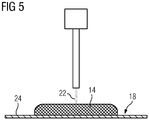
- FIG 5 shows a schematic representation of a method for producing at least one at least partially printed permanent magnet 14 on a base plate 24, the permanent magnet 14 being produced at least partially by means of cold gas spraying.
- solid particles 22 are sprayed directly onto the base plate 26, solid particles 22 made of a magnetic material being used.
- the solid particles 22 have, for example, iron, nickel, cobalt, samarium-cobalt, aluminum-nickel-cobalt, neodymium-iron-boron and / or samarium-iron-nickel.
- Solid particles 22 of at least two magnetic materials with different magnetic properties are optionally used.
- a hard magnetic material such as neodymium iron boron and a soft magnetic material such as iron.
- a cover 20 is arranged on the permanent magnet 14 and connected to the base plate 24. After the production of the at least one permanent magnet 14, it is magnetized.
- the further configuration of the permanent magnet 14 in FIG 5 corresponds to that in FIG 4 .
- FIG 6 shows a schematic representation of a second method for producing a rotor 6.
- solid particles 22 are sprayed directly onto the base plate 26, so that the permanent magnet 14 is connected directly to the base plate 26.
- a magnet module 26 is produced by spraying a cover 20 onto the permanent magnet 14 and the base plate 24 by means of cold gas spraying, so that the cover 20 is connected to both the permanent magnet 14 and the base plate 24.
- the at least one permanent magnet 14 is magnetized after the manufacture of the magnet module 26.
- the magnet module 26 is placed on a surface 16 of a rotor element 12 carrying a magnetic field, as in FIG FIG 3 shown, fixed with cold gas spraying.
- the rotor surface 16 is designed as a traverse surface, so that the flat base plate 26 lies flat on the rotor surface 16.
- FIG 7 shows a schematic representation of a third method for producing a rotor 6. Since the rotor 6 is designed as an external rotor, the rotor surface 6 is concave.
- the base plate 24 has a convex contact surface corresponding to the rotor surface 6, so that the base plate 24 can be connected to the rotor surface 6 in a planar manner.
- the base plate 24 has a cross section in the form of a segment of a circle.
- the rotor 6 is designed as an inner rotor, the rotor surface 6 being convex in the case of an inner rotor.
- the further design of the manufacturing process in FIG 7 corresponds to that in FIG 6 .
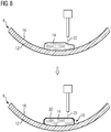
- FIG 8 shows a schematic representation of a fourth method for producing a rotor 6.
- at least one permanent magnet 14 is produced, at least partially, by means of cold gas spraying.
- solid particles 22 made of at least one magnetic material are sprayed directly onto the concave rotor surface 16 by means of cold gas spraying, so that the permanent magnet 14 is connected directly to the rotor element 12 of the rotor 6 carrying the magnetic field.
- a cover 20 is sprayed directly onto the permanent magnet 14 and the magnetic field-carrying rotor element 12 by means of cold gas spraying, so that the cover 20 is connected both to the permanent magnet 14 and to the magnetic field-carrying rotor element 12 of the rotor 6.
- the further design of the manufacturing process in FIG 8 corresponds to that in FIG 7 .
- FIG. 9 shows a schematic representation of a fifth method for producing a rotor 6.
- the connection is established by spraying the electrically conductive non-magnetic solid particles 22 by means of cold gas spraying in such a way that the cover 20 is connected to the rotor element 12 carrying the magnetic field
- the at least one permanent magnet 14 is then introduced in the axial direction between the cover 20 and the rotor surface 16.
- the further configuration of the rotor 6 in FIG. 9 corresponds to that in FIG 2 .
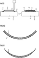
- FIG 10 shows a cross-sectional view of a first embodiment of a permanent magnet 14 which is designed as a shell magnet.
- the shell magnet is produced using an additive manufacturing method, in particular by means of cold gas spraying, and has a convex contact surface 28, which is designed to correspond to a concave rotor surface 16 of an external rotor, so that the shell magnet can be made contact with the rotor surface 16 of the external rotor.
- FIG 11 shows a cross-sectional view of a second embodiment of a permanent magnet 14, which is designed as a sickle magnet.
- the sickle magnet is produced using an additive manufacturing process, in particular using cold gas spraying, and its shape can also be used in a PM reluctance machine.
- FIG 12 shows a cross-sectional view of a third embodiment of a permanent magnet 14, which is produced using an additive manufacturing method, in particular by means of cold gas spraying, from materials with locally different magnetic properties, so that the permanent magnet 14, at least in cross section, has areas of different magnetic flux density B1, B2, B3.
- the permanent magnet 14 has a maximum in the middle magnetic flux density B1 as it decreases along the contact surface 28.
- the further configuration of the permanent magnet 14 in FIG 12 corresponds to that in FIG 2 .
- FIG. 13 shows a schematic representation of a first embodiment of an arrangement of permanent magnets 14 on a rotor surface 16.
- the permanent magnets 14 are produced using an additive manufacturing method, in particular by means of cold gas spraying, and are designed as arrow magnets.
- the arrow shape of the permanent magnets 14 is axially symmetrical in the axial direction A.
- the arrow magnets are alternately magnetized with essentially the same distances d1 in the circumferential direction U on the rotor surface 16.
- FIG 14 shows a schematic representation of a second embodiment of an arrangement of permanent magnets 14 on a rotor surface 16.
- the permanent magnets 14 are produced using an additive manufacturing method, in particular by means of cold gas spraying, and have a bevel in the axial direction A.
- the bevel is designed such that the permanent magnets 14 run in the axial direction parallel and at the same distance d1 from one another.
- the further configuration of the permanent magnets 14 in FIG 14 corresponds to that in FIG. 13 .
- FIG. 15 shows a schematic representation of a third embodiment of an arrangement of permanent magnets 14 on a rotor surface 16.
- the permanent magnets 14 have a pole offset.
- the permanent magnets 14 have different distances d1, d2 from one another in the circumferential direction U. As an example, the order of the distances d1, d2 is repeated periodically.
- the further configuration of the permanent magnets 14 in FIG. 15 corresponds to that in FIG 14 .
- FIG 16 shows a schematic representation of a wind turbine 30 with an electrical rotating machine 2.
- the wind turbine 30 there is an embodiment of an inventive electric rotating machine 2 for use.
- the electric rotating machine 2 used as a generator is driven directly (as a direct drive) or via a gear.
- the invention relates to a method for producing a rotor 6 for an electrical rotating machine 2 with a magnetic field-guiding, in particular eddy current-suppressing, rotor element 12 and at least one permanent magnet 14.
- a magnetic field-guiding, in particular eddy current-suppressing, rotor element 12 and at least one permanent magnet 14.
- the permanent magnet 14 be connected to the magnetic field-carrying rotor element 12 by means of an additive manufacturing method.
Landscapes
- Engineering & Computer Science (AREA)
- Power Engineering (AREA)
- Manufacturing & Machinery (AREA)
- Manufacture Of Motors, Generators (AREA)
- Permanent Field Magnets Of Synchronous Machinery (AREA)
Priority Applications (2)
| Application Number | Priority Date | Filing Date | Title |
|---|---|---|---|
| EP18197408.0A EP3629454A1 (fr) | 2018-09-28 | 2018-09-28 | Procédé de fabrication d'un rotor pour une machine à rotation électrique |
| PCT/EP2019/074812 WO2020064418A1 (fr) | 2018-09-28 | 2019-09-17 | Procédé de fabrication d'un rotor pour une machine tournante électrique |
Applications Claiming Priority (1)
| Application Number | Priority Date | Filing Date | Title |
|---|---|---|---|
| EP18197408.0A EP3629454A1 (fr) | 2018-09-28 | 2018-09-28 | Procédé de fabrication d'un rotor pour une machine à rotation électrique |
Publications (1)
| Publication Number | Publication Date |
|---|---|
| EP3629454A1 true EP3629454A1 (fr) | 2020-04-01 |
Family
ID=63708186
Family Applications (1)
| Application Number | Title | Priority Date | Filing Date |
|---|---|---|---|
| EP18197408.0A Withdrawn EP3629454A1 (fr) | 2018-09-28 | 2018-09-28 | Procédé de fabrication d'un rotor pour une machine à rotation électrique |
Country Status (2)
| Country | Link |
|---|---|
| EP (1) | EP3629454A1 (fr) |
| WO (1) | WO2020064418A1 (fr) |
Cited By (4)
| Publication number | Priority date | Publication date | Assignee | Title |
|---|---|---|---|---|
| EP4191836A3 (fr) * | 2021-12-03 | 2024-01-03 | Hamilton Sundstrand Corporation | Fabrication additive d'une roue de pompe comprenant un rotor de moteur électrique |
| US12117016B2 (en) | 2021-12-03 | 2024-10-15 | Hamilton Sundstrand Corporation | Shaftless rotary machine |
| DE102024120492A1 (de) * | 2024-07-19 | 2026-01-22 | Bayerische Motoren Werke Aktiengesellschaft | Rotor für eine elektrische maschine |
| DE102024120493A1 (de) * | 2024-07-19 | 2026-01-22 | Bayerische Motoren Werke Aktiengesellschaft | Rotor für eine elektrische maschine |
Citations (9)
| Publication number | Priority date | Publication date | Assignee | Title |
|---|---|---|---|---|
| EP1263006A2 (fr) * | 2001-05-30 | 2002-12-04 | Ford Motor Company | Méthode de fabrication d'un aimant permanent comprenant de pulvérisation cinétique et appareils électromagnétiques utilisant cette méthode |
| EP1844181A1 (fr) | 2005-02-02 | 2007-10-17 | Siemens Aktiengesellschaft | Procede de pulverisation par gaz froid |
| DE102010041593A1 (de) | 2010-09-29 | 2012-03-29 | Siemens Aktiengesellschaft | Magnetpolabdeckung einer elektrischen Maschine |
| DE102012006248A1 (de) | 2011-04-04 | 2012-10-04 | Fanuc Corporation | Kurzschlussläufer und dessen Herstellungsverfahren |
| EP2555385A1 (fr) | 2011-08-01 | 2013-02-06 | Siemens Aktiengesellschaft | Ensemble formant aimant permanent doté d'un couvercle moulé en plastique et procédé pour protéger un aimant permanent |
| EP2587633A1 (fr) | 2010-06-28 | 2013-05-01 | Gamesa Innovation & Technology, S.L. | Module de plaque de couverture d'aimants pour génératrices, agencement, et procédé de montage et de démontage dudit module |
| EP2930825A1 (fr) * | 2014-04-11 | 2015-10-14 | Siemens Aktiengesellschaft | Montage d'aimants permanents sur un rotor d'une machine électrique |
| DE102014211113A1 (de) * | 2014-06-11 | 2015-12-17 | Robert Bosch Gmbh | Rotor oder Stator für eine elektrische Maschine mit verbesserter Flussführung |
| WO2016051568A1 (fr) * | 2014-10-02 | 2016-04-07 | 三菱電機株式会社 | Rotor de machine électrique rotative et procédé de production d'un rotor de machine électrique rotative |
-
2018
- 2018-09-28 EP EP18197408.0A patent/EP3629454A1/fr not_active Withdrawn
-
2019
- 2019-09-17 WO PCT/EP2019/074812 patent/WO2020064418A1/fr not_active Ceased
Patent Citations (9)
| Publication number | Priority date | Publication date | Assignee | Title |
|---|---|---|---|---|
| EP1263006A2 (fr) * | 2001-05-30 | 2002-12-04 | Ford Motor Company | Méthode de fabrication d'un aimant permanent comprenant de pulvérisation cinétique et appareils électromagnétiques utilisant cette méthode |
| EP1844181A1 (fr) | 2005-02-02 | 2007-10-17 | Siemens Aktiengesellschaft | Procede de pulverisation par gaz froid |
| EP2587633A1 (fr) | 2010-06-28 | 2013-05-01 | Gamesa Innovation & Technology, S.L. | Module de plaque de couverture d'aimants pour génératrices, agencement, et procédé de montage et de démontage dudit module |
| DE102010041593A1 (de) | 2010-09-29 | 2012-03-29 | Siemens Aktiengesellschaft | Magnetpolabdeckung einer elektrischen Maschine |
| DE102012006248A1 (de) | 2011-04-04 | 2012-10-04 | Fanuc Corporation | Kurzschlussläufer und dessen Herstellungsverfahren |
| EP2555385A1 (fr) | 2011-08-01 | 2013-02-06 | Siemens Aktiengesellschaft | Ensemble formant aimant permanent doté d'un couvercle moulé en plastique et procédé pour protéger un aimant permanent |
| EP2930825A1 (fr) * | 2014-04-11 | 2015-10-14 | Siemens Aktiengesellschaft | Montage d'aimants permanents sur un rotor d'une machine électrique |
| DE102014211113A1 (de) * | 2014-06-11 | 2015-12-17 | Robert Bosch Gmbh | Rotor oder Stator für eine elektrische Maschine mit verbesserter Flussführung |
| WO2016051568A1 (fr) * | 2014-10-02 | 2016-04-07 | 三菱電機株式会社 | Rotor de machine électrique rotative et procédé de production d'un rotor de machine électrique rotative |
Cited By (5)
| Publication number | Priority date | Publication date | Assignee | Title |
|---|---|---|---|---|
| EP4191836A3 (fr) * | 2021-12-03 | 2024-01-03 | Hamilton Sundstrand Corporation | Fabrication additive d'une roue de pompe comprenant un rotor de moteur électrique |
| US12076930B2 (en) | 2021-12-03 | 2024-09-03 | Hamilton Sundstrand Corporation | Additively manufacturing an impeller and motor rotor |
| US12117016B2 (en) | 2021-12-03 | 2024-10-15 | Hamilton Sundstrand Corporation | Shaftless rotary machine |
| DE102024120492A1 (de) * | 2024-07-19 | 2026-01-22 | Bayerische Motoren Werke Aktiengesellschaft | Rotor für eine elektrische maschine |
| DE102024120493A1 (de) * | 2024-07-19 | 2026-01-22 | Bayerische Motoren Werke Aktiengesellschaft | Rotor für eine elektrische maschine |
Also Published As
| Publication number | Publication date |
|---|---|
| WO2020064418A1 (fr) | 2020-04-02 |
Similar Documents
| Publication | Publication Date | Title |
|---|---|---|
| EP3131189B1 (fr) | Rotor d'une machine electrique | |
| EP1495527B1 (fr) | Machine electrique, notamment moteur excite par aimant permanent | |
| EP2962383B1 (fr) | Machine à flux axial légère | |
| DE102013012605B4 (de) | Rotierende elektrische Maschine und Verfahren zum Herstellen von Magnetpolschuhen | |
| DE102015111480A1 (de) | Rotor und elektrische Maschine | |
| DE102011111352B4 (de) | Elektromotor mit eisenloser Wicklung | |
| DE102019107398A1 (de) | Axialflussrotor und elektrische axialflussmaschine | |
| AT522711A1 (de) | Stator für eine Axialflussmaschine | |
| DE102008057863A1 (de) | Herstellung einer Elektromotorkomponente | |
| EP2255431A1 (fr) | Entraînement direct à faible inertie et puissance volumique élevée | |
| EP3499687B1 (fr) | Rotor d'une machine électrique | |
| DE112014007129T5 (de) | Statorkern für eine elektrische Rotationsmaschine, elektrische Rotationsmaschine und Verfahren zur Herstellung einer elektrischen Rotationsmaschine | |
| EP3629454A1 (fr) | Procédé de fabrication d'un rotor pour une machine à rotation électrique | |
| DE102010061784A1 (de) | Optimierter Speichenrotor | |
| DE4423840A1 (de) | Radialmagnetmotor | |
| EP3821521B1 (fr) | Procédé de fabrication d'un rotor pour une machine à rotation électrique | |
| DE112019007070T5 (de) | Rotierende elektrische maschine | |
| DE4406471A1 (de) | Rotatorische elektrische Maschine | |
| EP2319164B1 (fr) | Rotor pour une machine électrique à couple de détente réduit | |
| EP2628237B1 (fr) | Rotor aux aimants permanents pour moteur électrique | |
| DE102015213624A1 (de) | Permanent erregte elektrische Maschine mit optimierter Geometrie | |
| DE102012221039A1 (de) | Neuartiges Rotorelement für eine permanenterregte Transversalflussmaschine sowie Magnetisierungsvorrichtung und Herstellungsverfahren | |
| EP3057203A1 (fr) | Rotor d'une machine synchrone à excitation permanente et son procédé de fabrication | |
| DE202004002372U1 (de) | Elektromotor | |
| WO2020043826A1 (fr) | Machine électrique, procédé de fabrication d'une machine électrique et véhicule électrique |
Legal Events
| Date | Code | Title | Description |
|---|---|---|---|
| PUAI | Public reference made under article 153(3) epc to a published international application that has entered the european phase |
Free format text: ORIGINAL CODE: 0009012 |
|
| STAA | Information on the status of an ep patent application or granted ep patent |
Free format text: STATUS: THE APPLICATION HAS BEEN PUBLISHED |
|
| AK | Designated contracting states |
Kind code of ref document: A1 Designated state(s): AL AT BE BG CH CY CZ DE DK EE ES FI FR GB GR HR HU IE IS IT LI LT LU LV MC MK MT NL NO PL PT RO RS SE SI SK SM TR |
|
| AX | Request for extension of the european patent |
Extension state: BA ME |
|
| STAA | Information on the status of an ep patent application or granted ep patent |
Free format text: STATUS: THE APPLICATION IS DEEMED TO BE WITHDRAWN |
|
| 18D | Application deemed to be withdrawn |
Effective date: 20201002 |