EP3629455A1 - Verfahren zur herstellung eines rotors eines elektromotors - Google Patents
Verfahren zur herstellung eines rotors eines elektromotors Download PDFInfo
- Publication number
- EP3629455A1 EP3629455A1 EP18197656.4A EP18197656A EP3629455A1 EP 3629455 A1 EP3629455 A1 EP 3629455A1 EP 18197656 A EP18197656 A EP 18197656A EP 3629455 A1 EP3629455 A1 EP 3629455A1
- Authority
- EP
- European Patent Office
- Prior art keywords
- rotor
- chassis
- flange
- magnet
- electric motor
- Prior art date
- Legal status (The legal status is an assumption and is not a legal conclusion. Google has not performed a legal analysis and makes no representation as to the accuracy of the status listed.)
- Withdrawn
Links
Images


Classifications
-
- H—ELECTRICITY
- H02—GENERATION; CONVERSION OR DISTRIBUTION OF ELECTRIC POWER
- H02K—DYNAMO-ELECTRIC MACHINES
- H02K15/00—Processes or apparatus specially adapted for manufacturing, assembling, maintaining or repairing of dynamo-electric machines
- H02K15/02—Processes or apparatus specially adapted for manufacturing, assembling, maintaining or repairing of dynamo-electric machines of stator or rotor bodies
- H02K15/03—Processes or apparatus specially adapted for manufacturing, assembling, maintaining or repairing of dynamo-electric machines of stator or rotor bodies having permanent magnets
-
- H—ELECTRICITY
- H02—GENERATION; CONVERSION OR DISTRIBUTION OF ELECTRIC POWER
- H02K—DYNAMO-ELECTRIC MACHINES
- H02K1/00—Details of the magnetic circuit
- H02K1/06—Details of the magnetic circuit characterised by the shape, form or construction
- H02K1/22—Rotating parts of the magnetic circuit
- H02K1/27—Rotor cores with permanent magnets
- H02K1/2706—Inner rotors
- H02K1/272—Inner rotors the magnetisation axis of the magnets being perpendicular to the rotor axis
- H02K1/2726—Inner rotors the magnetisation axis of the magnets being perpendicular to the rotor axis the rotor consisting of a single magnet or two or more axially juxtaposed single magnets
- H02K1/2733—Annular magnets
-
- H—ELECTRICITY
- H02—GENERATION; CONVERSION OR DISTRIBUTION OF ELECTRIC POWER
- H02K—DYNAMO-ELECTRIC MACHINES
- H02K11/00—Structural association of dynamo-electric machines with electric components or with devices for shielding, monitoring or protection
- H02K11/20—Structural association of dynamo-electric machines with electric components or with devices for shielding, monitoring or protection for measuring, monitoring, testing, protecting or switching
- H02K11/21—Devices for sensing speed or position, or actuated thereby
Definitions
- the present invention relates to a method for manufacturing a rotor for an electric motor, preferably a brushless motor, for a wiper system of an automotive vehicle.
- Electric motors comprise, in the most general sense, two main components: a stator, which remains stationary; and a rotor, which rotates within the stator. Both the rotor and the stator comprise means for generating a magnetic field, the magnetic field of the stator interacting with the magnetic field of the rotor in such a way as to drive the latter in rotation.
- the rotor comprises a chassis holding a plurality of permanent magnets while the stator comprises electromagnetic excitation coils.
- This chassis may be, for instance, cylinder-, disc-, bell-, or puck-shaped.
- the electric motor is configured so that when the coils are powered with electric current, a magnetic field is created.
- the magnetic field of the stator excitation coils interacts with the magnetic field of the rotor permanent magnets, exerting a force on the rotor and causing a rotational movement of the magnets about an axis of rotation.
- the excitation coils of the stator are switched by an electronic control system, which energizes the excitation coils with precise timing so as to generate the desired rotation of the rotor.
- the rotor further comprises a shaft comprising an endless screw whose external threads mesh with teeth of a wheel, the wheel being fixed to an output shaft of the motor.
- the rotor magnets are usually fixed to the chassis with strong glue that can be a harmful substance, particularly to the person assembling the motor.
- chassis might not be firmly attached, which degrades the performances of the electric motor.
- the present invention aims at overcoming or mitigating at least some of these shortcomings.
- the present invention relates to a method for manufacturing a rotor for an electric motor of a wiper system for an automotive vehicle, the method comprising a step of forming a chassis of the rotor, the step of forming said chassis comprising overmolding at least one magnet on at least one flange.
- the claimed method is particularly easy to implement, reducing its cost and time.
- the magnets are securely attached, which ensures optimized performances of the motor.
- said at least one flange comprises slots for determining a rotation speed of the rotor.
- said at least one magnet is overmolded on two flanges, the method comprising a step of contacting the flanges one with another.
- the two flanges are identical and positioned head to tail.
- the method comprises a step of fixing the flanges one to another.
- the method comprises a step of mounting the chassis on a shaft comprising an endless screw.
- the method comprises a chassis, said chassis comprising at least one magnet overmolded on at least one flange for closing magnetic field lines.
- the invention also relates to a rotor for an electric motor of a wiper system for an automotive vehicle, comprising a chassis, said chassis comprising at least one magnet overmolded on at least one flange for closing magnetic field lines.
- said at least one flange comprises slots for determining a rotation speed of the chassis.
- the rotor comprises two flanges positioned head to tail.
- the invention also relates to an electric motor comprising a rotor as already described.
- the invention also relates to a wiper system comprising an electric motor as already described.
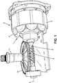
- the invention relates to a rotor 1 of an electric motor 2 for a wiper system and the associated method for manufacturing the rotor 1.
- the electric motor is preferably brushless.
- the electric motor 2 comprises a stator 5.
- the stator 5 comprises a plurality of electromagnetic excitation coils 6 of the rotor 1.
- the rotor 1 comprises at least one multipole magnet 7, detailed later, and mounted to be driven in a rotational movement about an axis of rotation, referenced L.
- the electric motor 2 is configured so that the rotor 1 rotates in the stator 5, which causes a rotation of a shaft 8 extending along the axis of rotation L.
- the shaft 8 comprises a threaded portion 9 mounted to be engaged by a gear wheel 10.
- the wheel 10 rotates an output shaft 11.
- the output shaft 11 is substantially perpendicular to the drive shaft 8.
- the rotor 1 comprises at least one magnet 7.
- the rotor 1 comprises a single magnet 7 which has a shape of an open cylinder.
- the rotor 1 also comprises at least one flange 20 for closing lines of the magnetic field generated by the magnetic coils.
- Each flange 20 is advantageously made of soft iron.
- Each flange has a shape of an open cylindrical delimiting a passage 21 for the shaft 8.
- the magnet 7 is overmolded on each flange 20 so as to form a chassis 22.
- the overmolding material is referenced 23 on the figures.
- the chassis 22 comprises at least one area 24 from which material can be removed for balancing the motor 2.
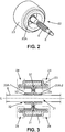
- the rotor 1 is now described in reference to the embodiment of figures 2-4 .
- the rotor 1 comprises two flanges 20-1 and 20-2.
- the flanges 20-1, 20-2 are identical.
- Each flange 20-1, 20-2 comprises a longitudinal cylindrical surface 25 delimiting two ends 26, 27 of the flange 20-1, 20-2.
- the end 26 is open while the end 27 comprises a radial surface 28 provided with a central open protuberance 29 extending inside and parallel to the surface 25.
- the flanges 20 are disposed head to tail, the radial surface 28 of the flange 20-1 contacting the radial surface 28 of the flange 20-2.
- the protuberances 29 of the flanges 20-1 and 20-2 constitute the passage 21 of the shaft 8.
- the flanges 20-1, 20-2 are fixed one to another preferably by laser welding.
- the laser welding points are referenced 30.
- the flanges 20-1, 20-2 are located inside the magnet 7.
- Overmolding material 23 is disposed around the magnet 7, around the ends 26 to the ends 27 and along the surfaces 25 of the flanges 20-1 and 20-2.
- the rotor 1 is now described in reference to the embodiment of figures 5-6 .
- the rotor 1 comprises a single flange 20.
- the flange 20 comprises a longitudinal cylindrical surface 25 delimiting two ends 26, 27 of the flange 20.
- the end 26 is open while the end 27 comprises a radial surface 28 provided with a central open protuberance 29 extending inside and parallel to the surface 25.
- the protuberance 29 forms the passage 21 of the shaft 8.
- the flange 20 is located inside the magnet 7.
- Overmolding material 23 is disposed around the magnet 7, around the end 26 to the end 27 and along the surfaces 25 of the flange 20.
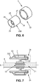
- the rotor 1 is now described in reference to the embodiment of figures 8-9 .
- the rotor 1 comprises a single flange 20.
- the flange 20 comprises a longitudinal cylindrical surface 25 delimiting two ends 26, 27 of the flange 20.
- the end 26 is open while the end 27 comprises a radial surface 28 provided with a central open protuberance 29 extending inside and parallel to the surface 25.
- the protuberance 29 forms the passage 21 of the shaft 8.
- the end 26 comprises a shoulder 30 provided with slots 31 for detecting the position of the shaft 8 when the rotor 1 rotates, hence determining its rotation speed.
- the flange 20 is located inside the magnet 7.
- Overmolding material 23 is disposed around the magnet 7, around the end 27 and along the surface 25 of the flange 20.
- the shoulder 30 protrudes outside the magnet 7 and is not covered by overmolding material 23.
- the method comprises a step of forming the chassis 22, by overmolding the magnet 7 on each flange 20.
- the method comprises a preliminary step of positioning each flange 20 in the magnet 7.
- the method comprises a step of sliding the flanges 20-1, 20-2 inside the magnet 7 so that the surfaces 28 contact each other.
- the method also comprises a step of laser welding the flanges 20-1, 20-2 to fix them together (points 31 on figure 3 ).
- the method comprises a step of sliding the flange 20 inside the magnet 7.
- the method comprises a step of sliding the flange 20 inside the magnet 7, the end 26 protruding outside the magnet 7.
- the method then comprises a step of assembling the chassis 22 to the shaft 8.
- Assembling the chassis 22 to the shaft 8 comprises sliding the shaft 8 in the protuberance(s) 29 of the flange(s) 20 and then fixing the shaft to the chassis 22, for instance with laser welding (points 32 on figure 3 ) and/or thanks to notches 33 ( figures 5 and 7 on the shaft 8).
Landscapes
- Engineering & Computer Science (AREA)
- Manufacturing & Machinery (AREA)
- Power Engineering (AREA)
- Manufacture Of Motors, Generators (AREA)
- Permanent Field Magnets Of Synchronous Machinery (AREA)
Priority Applications (2)
| Application Number | Priority Date | Filing Date | Title |
|---|---|---|---|
| EP18197656.4A EP3629455A1 (de) | 2018-09-28 | 2018-09-28 | Verfahren zur herstellung eines rotors eines elektromotors |
| PCT/EP2019/076196 WO2020065017A1 (en) | 2018-09-28 | 2019-09-27 | Method for manufacturing a rotor of an electric motor |
Applications Claiming Priority (1)
| Application Number | Priority Date | Filing Date | Title |
|---|---|---|---|
| EP18197656.4A EP3629455A1 (de) | 2018-09-28 | 2018-09-28 | Verfahren zur herstellung eines rotors eines elektromotors |
Publications (1)
| Publication Number | Publication Date |
|---|---|
| EP3629455A1 true EP3629455A1 (de) | 2020-04-01 |
Family
ID=63713691
Family Applications (1)
| Application Number | Title | Priority Date | Filing Date |
|---|---|---|---|
| EP18197656.4A Withdrawn EP3629455A1 (de) | 2018-09-28 | 2018-09-28 | Verfahren zur herstellung eines rotors eines elektromotors |
Country Status (2)
| Country | Link |
|---|---|
| EP (1) | EP3629455A1 (de) |
| WO (1) | WO2020065017A1 (de) |
Citations (5)
| Publication number | Priority date | Publication date | Assignee | Title |
|---|---|---|---|---|
| EP0308647A1 (de) * | 1987-08-26 | 1989-03-29 | Siemens Aktiengesellschaft | Verfahren zur Herstellung eines Festsitzes zwischen einer Rotorwelle und einem umspritzten Rotationskörper |
| JP2002369423A (ja) * | 2001-06-12 | 2002-12-20 | Mitsuba Corp | 回転電機の回転子 |
| EP1515419A2 (de) * | 2003-09-05 | 2005-03-16 | Robert Bosch Gmbh | Verfahren zur Magnetisierung von Magnetelementen für eine elektrische Maschine |
| DE102010063323A1 (de) * | 2010-12-17 | 2012-06-21 | Robert Bosch Gmbh | Verfahren zur Herstellung einer Maschinenkomponente für eine elektrische Maschine sowie eine Maschinenkomponente |
| EP2811168A1 (de) * | 2012-01-31 | 2014-12-10 | Mitsubishi Electric Corporation | Pumpe, kältekreislaufvorrichtung und verfahren zur herstellung der pumpe |
Family Cites Families (1)
| Publication number | Priority date | Publication date | Assignee | Title |
|---|---|---|---|---|
| DE19836451C2 (de) * | 1998-08-12 | 2000-05-31 | Baermann Max Gmbh | Hochgefülltes Kunststoffteil |
-
2018
- 2018-09-28 EP EP18197656.4A patent/EP3629455A1/de not_active Withdrawn
-
2019
- 2019-09-27 WO PCT/EP2019/076196 patent/WO2020065017A1/en not_active Ceased
Patent Citations (5)
| Publication number | Priority date | Publication date | Assignee | Title |
|---|---|---|---|---|
| EP0308647A1 (de) * | 1987-08-26 | 1989-03-29 | Siemens Aktiengesellschaft | Verfahren zur Herstellung eines Festsitzes zwischen einer Rotorwelle und einem umspritzten Rotationskörper |
| JP2002369423A (ja) * | 2001-06-12 | 2002-12-20 | Mitsuba Corp | 回転電機の回転子 |
| EP1515419A2 (de) * | 2003-09-05 | 2005-03-16 | Robert Bosch Gmbh | Verfahren zur Magnetisierung von Magnetelementen für eine elektrische Maschine |
| DE102010063323A1 (de) * | 2010-12-17 | 2012-06-21 | Robert Bosch Gmbh | Verfahren zur Herstellung einer Maschinenkomponente für eine elektrische Maschine sowie eine Maschinenkomponente |
| EP2811168A1 (de) * | 2012-01-31 | 2014-12-10 | Mitsubishi Electric Corporation | Pumpe, kältekreislaufvorrichtung und verfahren zur herstellung der pumpe |
Also Published As
| Publication number | Publication date |
|---|---|
| WO2020065017A1 (en) | 2020-04-02 |
Similar Documents
| Publication | Publication Date | Title |
|---|---|---|
| US9692270B2 (en) | Motor including brackets and fixing members | |
| JP6431774B2 (ja) | 駆動装置 | |
| US12368363B2 (en) | Magnetic-geared motor and magnetic gear | |
| US11289960B2 (en) | Motor and brushless wiper motor | |
| JP2005020887A (ja) | 回転電機のマグネット固定構造及びマグネット固定方法 | |
| WO2016067532A1 (ja) | ブラシレスモータ及び電動工具 | |
| US20040061410A1 (en) | Permanent magnet type electric rotating machine | |
| CN109560662A (zh) | 具有旋转轴、转子和平衡盘的驱动装置 | |
| EP3883092B1 (de) | Rotor, motor und bürstenloser motor | |
| KR20180041227A (ko) | 고정자 조립체 및 이를 포함하는 스테퍼 구동 모터 | |
| JPWO2020110191A1 (ja) | 回転電機 | |
| KR20180052167A (ko) | 직류 모터 | |
| WO2020054095A1 (ja) | 電動モータおよび電動モータの製造方法 | |
| WO2019157701A1 (en) | Outer rotor motor | |
| EP2744072A2 (de) | Motor | |
| WO2017126297A1 (ja) | 回転電機 | |
| JP2010022088A (ja) | 磁石回転型回転電機 | |
| JP2016181950A (ja) | 電動モータ、および電動モータの製造方法 | |
| CN116472658B (zh) | 旋转电机以及电动助力转向装置 | |
| WO2019187752A1 (ja) | 電動モータ | |
| WO2019198464A1 (ja) | モータ及びブラシレスワイパーモータ | |
| WO2020065017A1 (en) | Method for manufacturing a rotor of an electric motor | |
| JP6914443B2 (ja) | モータ及びバルブタイミング調整装置 | |
| CN104617693B (zh) | 用于电机的电机组件以及用于制造这样的电机组件的方法 | |
| EP3629456B1 (de) | Rotor und verfahren zur herstellung eines rotors eines elektromotors |
Legal Events
| Date | Code | Title | Description |
|---|---|---|---|
| PUAI | Public reference made under article 153(3) epc to a published international application that has entered the european phase |
Free format text: ORIGINAL CODE: 0009012 |
|
| STAA | Information on the status of an ep patent application or granted ep patent |
Free format text: STATUS: REQUEST FOR EXAMINATION WAS MADE |
|
| 17P | Request for examination filed |
Effective date: 20180928 |
|
| AK | Designated contracting states |
Kind code of ref document: A1 Designated state(s): AL AT BE BG CH CY CZ DE DK EE ES FI FR GB GR HR HU IE IS IT LI LT LU LV MC MK MT NL NO PL PT RO RS SE SI SK SM TR |
|
| AX | Request for extension of the european patent |
Extension state: BA ME |
|
| STAA | Information on the status of an ep patent application or granted ep patent |
Free format text: STATUS: EXAMINATION IS IN PROGRESS |
|
| 17Q | First examination report despatched |
Effective date: 20211004 |
|
| STAA | Information on the status of an ep patent application or granted ep patent |
Free format text: STATUS: THE APPLICATION IS DEEMED TO BE WITHDRAWN |
|
| 18D | Application deemed to be withdrawn |
Effective date: 20220215 |