EP3629718B1 - Système de dépuration - Google Patents
Système de dépuration Download PDFInfo
- Publication number
- EP3629718B1 EP3629718B1 EP18738383.1A EP18738383A EP3629718B1 EP 3629718 B1 EP3629718 B1 EP 3629718B1 EP 18738383 A EP18738383 A EP 18738383A EP 3629718 B1 EP3629718 B1 EP 3629718B1
- Authority
- EP
- European Patent Office
- Prior art keywords
- container
- drain
- drain canal
- canal unit
- corner
- Prior art date
- Legal status (The legal status is an assumption and is not a legal conclusion. Google has not performed a legal analysis and makes no representation as to the accuracy of the status listed.)
- Active
Links
Images



Classifications
-
- A—HUMAN NECESSITIES
- A01—AGRICULTURE; FORESTRY; ANIMAL HUSBANDRY; HUNTING; TRAPPING; FISHING
- A01K—ANIMAL HUSBANDRY; AVICULTURE; APICULTURE; PISCICULTURE; FISHING; REARING OR BREEDING ANIMALS, NOT OTHERWISE PROVIDED FOR; NEW BREEDS OF ANIMALS
- A01K63/00—Receptacles for live fish, e.g. aquaria; Terraria
- A01K63/02—Receptacles specially adapted for transporting live fish
-
- A—HUMAN NECESSITIES
- A01—AGRICULTURE; FORESTRY; ANIMAL HUSBANDRY; HUNTING; TRAPPING; FISHING
- A01K—ANIMAL HUSBANDRY; AVICULTURE; APICULTURE; PISCICULTURE; FISHING; REARING OR BREEDING ANIMALS, NOT OTHERWISE PROVIDED FOR; NEW BREEDS OF ANIMALS
- A01K61/00—Culture of aquatic animals
- A01K61/50—Culture of aquatic animals of shellfish
- A01K61/54—Culture of aquatic animals of shellfish of bivalves, e.g. oysters or mussels
-
- A—HUMAN NECESSITIES
- A01—AGRICULTURE; FORESTRY; ANIMAL HUSBANDRY; HUNTING; TRAPPING; FISHING
- A01K—ANIMAL HUSBANDRY; AVICULTURE; APICULTURE; PISCICULTURE; FISHING; REARING OR BREEDING ANIMALS, NOT OTHERWISE PROVIDED FOR; NEW BREEDS OF ANIMALS
- A01K61/00—Culture of aquatic animals
- A01K61/50—Culture of aquatic animals of shellfish
- A01K61/54—Culture of aquatic animals of shellfish of bivalves, e.g. oysters or mussels
- A01K61/55—Baskets therefor
-
- A—HUMAN NECESSITIES
- A22—BUTCHERING; MEAT TREATMENT; PROCESSING POULTRY OR FISH
- A22C—PROCESSING MEAT, POULTRY, OR FISH
- A22C29/00—Processing shellfish or bivalves, e.g. oysters, lobsters; Devices therefor, e.g. claw locks, claw crushers, grading devices; Processing lines
- A22C29/04—Processing bivalves, e.g. oysters
- A22C29/043—Cleaning operations on bivalves, e.g. evisceration, brushing, separation of meat and shell material
-
- B—PERFORMING OPERATIONS; TRANSPORTING
- B65—CONVEYING; PACKING; STORING; HANDLING THIN OR FILAMENTARY MATERIAL
- B65D—CONTAINERS FOR STORAGE OR TRANSPORT OF ARTICLES OR MATERIALS, e.g. BAGS, BARRELS, BOTTLES, BOXES, CANS, CARTONS, CRATES, DRUMS, JARS, TANKS, HOPPERS, FORWARDING CONTAINERS; ACCESSORIES, CLOSURES, OR FITTINGS THEREFOR; PACKAGING ELEMENTS; PACKAGES
- B65D21/00—Nestable, stackable or joinable containers; Containers of variable capacity
- B65D21/02—Containers specially shaped, or provided with fittings or attachments, to facilitate nesting, stacking, or joining together
- B65D21/0209—Containers specially shaped, or provided with fittings or attachments, to facilitate nesting, stacking, or joining together stackable or joined together one-upon-the-other in the upright or upside-down position
- B65D21/0213—Containers presenting a continuous stacking profile along the upper or lower edge of at least two opposite side walls
-
- A—HUMAN NECESSITIES
- A01—AGRICULTURE; FORESTRY; ANIMAL HUSBANDRY; HUNTING; TRAPPING; FISHING
- A01K—ANIMAL HUSBANDRY; AVICULTURE; APICULTURE; PISCICULTURE; FISHING; REARING OR BREEDING ANIMALS, NOT OTHERWISE PROVIDED FOR; NEW BREEDS OF ANIMALS
- A01K63/00—Receptacles for live fish, e.g. aquaria; Terraria
- A01K63/04—Arrangements for treating water specially adapted to receptacles for live fish
-
- Y—GENERAL TAGGING OF NEW TECHNOLOGICAL DEVELOPMENTS; GENERAL TAGGING OF CROSS-SECTIONAL TECHNOLOGIES SPANNING OVER SEVERAL SECTIONS OF THE IPC; TECHNICAL SUBJECTS COVERED BY FORMER USPC CROSS-REFERENCE ART COLLECTIONS [XRACs] AND DIGESTS
- Y02—TECHNOLOGIES OR APPLICATIONS FOR MITIGATION OR ADAPTATION AGAINST CLIMATE CHANGE
- Y02A—TECHNOLOGIES FOR ADAPTATION TO CLIMATE CHANGE
- Y02A40/00—Adaptation technologies in agriculture, forestry, livestock or agroalimentary production
- Y02A40/80—Adaptation technologies in agriculture, forestry, livestock or agroalimentary production in fisheries management
- Y02A40/81—Aquaculture, e.g. of fish
Definitions
- the present invention relates to a container system for the depuration of mollusk.
- the invention provides a system for depuration by means of a water circulation mechanism in a container.
- Depuration is a process of purging biological contaminants, such as bacteria, and impurities such as sand and silt, from marine and freshwater animals. Depuration is particularly used for filter feeders such as oysters, mussels and clams.
- the process usually involves the rinsing of the marine animals held in tanks with clean water, where the animals are allowed to filter feed to force out undesired contaminants.
- a constant flow of water is maintained, to allow for the removal of contaminants and faecal material, but at relatively low flow rates so that solid contaminants can settle at the bottom of the tank.
- Saeplast also known as Saeplast
- Saeplast 705 container an insulated container that is insulated and stackable, and useful in the depuration of mollusks.
- the tank has recirculation channels molded into two of its corners, such that when the container is filled with water, there is forced recirculation of water through the recirculation channels. Recirculated water is subsequently released from the container through an opening in its floor, so that when placed in a stack of containers, water is released into an adjacent container in a stack.
- EP 2567720 A1 discloses a depuration container that has two recirculation lines molded into its corners, so that water can be forced through the two lines.
- the container has a release opening having an elliptical shape in its base, to discharge water from the container in an oblique fashion so as to promote turbulent flow of water from the container.
- depuration is a process of removing sand, grit and biological contaminants such as bacteria, it is extremely important that the containers used for the depuration can be cleaned and disinfected.
- the closed circulation systems known in the art suffer from the disadvantage that the recirculation channels are typically molded into the structure of the container. The recirculation portion of the container can thus not be cleaned separately and/or replaced, should it become clogged or otherwise permanently polluted.
- ES 2187326 A1 discloses a depuration container having recirculation lines that are not molded into the container.
- the present invention addresses the above described deficiencies, by providing a container system that is suitable for the depuration of mollusks.
- the system comprises a container that is stackable and useful for depuration of mollusks, and at least one drain canal unit, that is designed to be interconnectable with corner parts of the container, so as to provide a closed circulation route within the container when engaged.
- a two-part container system is provided, where each part can be separately produced.
- the system can be used in combination with the prior art system of the present applicants, i.e. the Saeplast 705 depuration container. More importantly, the system allows for improved cleaning of the circulation channels of the container system, including the possibility of separately cleaning and/or replacing the drain canal unit.
- the invention provides a container assembly according to claim 1.
- each circulation route has an entry portion, between the drain canal unit and the floor of the container provided by a gap between the drain channel unit and the floor of the container, a corner channel portion comprising at least one circulation channel, between the drain canal unit and a container corner, and a drain channel portion, within the drain canal unit.
- the drain canal unit of the invention can be used in a container assembly for depuration of mollusks.
- a drain canal unit for use in stackable containers to allow circulation of water within individual containers in a stack of containers and drainage into adjacent containers in a stack, the drain canal unit comprising
- the drain canal unit thus serves two roles. One is to provide a barrier between the main cavity of the container and the corner portion of the container, so that water can not enter into the corner portion (the circulation channel), between the drain canal unit and the corner of the container, except by flowing through the gap between the drain canal unit and the container floor.
- the second role is to provide a drain canal, into which water can flow, through an entry opening at or near the upper end of the drain canal body, and be drained through the container floor, via the spout arranged on the lower end of the drain canal body.
- the first surface when the drain canal unit is engaged with a container, thus faces the main cavity of the container, while the second surface faces a corner of the container and is interconnected with side walls that meet at that corner.
- a distinct advantage of providing a depuration system as a two-part assembly is that each part can be manufactured independently. Thereby, complex molding of a container that includes drain canals to provide circulation and drainage of water in the container is avoided. Instead, the container itself has a much simpler structure, with no closed internal channels that can be difficult to mold and also can be difficult to clean or disinfect.
- the drain canal unit is thus preferably manufactured separately from the container. If one or more drain canal unit becomes very contaminated or clogged, the unit can be replaced at minimial cost, since its production is much cheaper than that of the container. Further, the drain canal unit is easier to handle, and can be cleaned and/or disinfected using industrial cleaning and disinfecting systems in a rather simple fashion. By comparison, the containers themselves are typically large and heavy, and thus difficult to handle. Thus, during operation, drain canal units can simply be replaced as needed, and subsequently taken away for deep cleaning and/or disinfection. Thereby, a user-friendly and efficient depuration system is provided.
- drain canal entry opening there is an opening on the drain canal unit, a drain canal entry opening, that faces the corner of a container when the drain canal unit is engaged with the container.
- the drain canal entry opening is provided near the upper end of its elongated body.
- a circulation route for water within the container can flow from the body of the container holding the drain canal unit, between the drain canal unit and the container floor, and into the corner portion of the container. Water will then flow, forced by water pressure within the container, through and up the circulation channel or channels within the corner portion, framed by the container body and the drain canal unit.
- water will flow into the drain canal unit via an entry opening to enter the drain canal within the cavity of the drain canal unit, and subsequently water is drained from the container through the spout on the drain canal unit.
- the drain canal unit can have dimensions that are adjusted so that its height, when engaged with a container, approximately matches that of the container.
- the drain canal unit when engaged with the container, does not extend beyond the upper rim of the container.
- the drain canal body can have a top surface that interconnects with the first surface, the second surface and the side surfaces and wherein the length of the drain canal structure is such that, when engaged with a container, the top surface does not vertically extend beyond the upper rim of the container.
- the drain canal body can comprise a solid approximately flat top surface.
- the top surface of the drain canal body can also be slighly tilted towards either the first or second (side) surface. Alternatively, the top surface can be curved or otherwise be tilted towards both the first and second side surfaces.
- the top surface is preferably solid, i.e. the surface is not permeable to liquid so as to ensure that the drain canal within the drain canal body is closed, water only being able to enter and exit through the drain canal entry opening and the spout, respectively.
- Water will not circulate in the container until the water level in the container has reached the height of the entry opening on the drain canal unit.
- the entry opening on the drain canal unit can conveniently be provided near the top of the first surface of the drain canal unit. Thereby, water circulation in the container will not take place until the container is nearly full, providing conditions for adequate depuration within the container, even when filled with mollusk.
- the container comprises slots on at least two of its inner side walls, near a corner of the container, wherein each slot is adapted to receive an peripheral portion of the drain canal unit, so that when engaged, the drain canal unit is interlocked with the slots. Thereby, the drain canal unit is locked in place with the container, to define a circulation route for water within the container.
- the slots can be vertical, to receive a drain canal unit of approximately constant width.
- the drain canal unit will then slide into the slots from above, i.e. the drain canal unit will be vertically provided into the slots.
- the slots can however also be tilted towards the corner, to accommodate a drain canal unit that is narrower at its bottom end than its top end; in other words, the drain canal unit may we wider at its top end than its bottom end.
- the slots can be of uniform depth and width.
- the slots can suitably however also be narrower and/or less deep at their lower end, to accommodate a drain canal unit that is slightly thinner at its bottom end and/or is accommodated at a slight angle, i.e. not completely perpendicular to the container floor.
- connection between slots on the side walls of the container and the drain canal unit are preferably tight, so as to minimize leakage through the connections.
- the connection is approximately water tight when the container is filled with water, i.e. the connection is able to withstand water pressure corresponding to the height of the container, with minimal leakage of water between the side walls of the container and the drain canal unit.
- connection between the spout and the container floor is water-tight.
- the spout and the opening in the container floor can be structured so that, when inserted into and through the floor of a container to form a watertight seal therebetween. Further, when inserted into the container floor, there is a gap present between the lower end of the drain canal body and the floor of the container. Thereby, water can flow under the drain canal unit and into the corner portion of the container.
- the drain canal unit spout is structured so that when inserted into the floor of the container, the entry portion of the circulation route is provided by a gap between the drain channel unit and the floor of the container.
- the opening on the spout can be arranged so as to face away from the drain canal entry opening. Thereby, when engaged with a container, water that is released from the drain canal unit is released towards the central portion of the body a below container in a stack of containers.
- the opening is arranged at the lower end of the spout.
- the circulation route can thus have an entry opening that is fluidly connected to the corner channel portion, such that water can flow upwardly and through the corner channel, into the drain canal of the drain canal unit, and drained downwardly through the drain canal to exit through the spout on the drain canal unit.
- the container can further comprise at least one protrusion along each side wall, wherein the protrusions are arranged to provide support for horizontal positioning of a removable drain plate within the container.
- Additional, or alternative, support for a drain plate can be provided in the container, for example by means of supports such as support knobs provided on the container floor. There can thus be provided a plurality of support protrusions or support knobs extending from the floor of the container, and which provide additional support for a drain plate.
- Such support members when present, are suitably provided so that they reach the same height as support protrusions on the side walls.
- the drain canal unit can also be provided with support means for a drain plate.
- the drain canal unit can be further adapted to provide, when engaged with the container, support for a removable drain plate within the container.
- the support can comprise a ledge or shelf on the drain canal body, so that when inserted into the container floor, there is provided a support for a drain plate that is placed in the container.
- the support is suitably provided at the same height as other support structures in the container assembly, so that the weight of the drain plate (which includes the weight of mollusks when loaded) is distributed among the support structures.
- the support means preferably are at the same height, so that the drain plate can be accommodated in a horizontal position in the container, with simultaneous support being provided by structures from the container protrusions and support ledge on the drain canal unit.
- the container in the container system can be stackable, such that one container can be placed on top of a second container, and so on.
- Support members (legs) extending downwardly from the bottom or floor of the container can be adapted to fit, when placed on top of another container, onto the upper rim of the container so that a snug and stable connection between the container is made.
- Such a connection can include having at least a portion of the upper rim configured so that it can receive legs or support members of a container so that the support members fit within an outer portion of the rim and sit on top of an inner portion or ledge of the rim, which can be provided as being lower (i.e., closer to the container floor) than an outer portion of the rim.
- the rim can at least partially container a ledge or shelf, such that container support members of a container can sit on the ledge or shelf, when placed on top of a container, so that a snug and stable stack of containers is formed.
- drain canal units There can be one or a plurality of drain canal units arranged in a container. There can for example be two drain canal units arranged in each container and that are arranged to be engaged with the container in proximity to opposite corners thereof, thereby forming two circulation routes in the container.
- the spout of a drain canal unit When engaged, the spout of a drain canal unit extends through the floor of a container, resulting in draining of water into an adjacent container in a stack.
- the spout can have an opening at its bottom end that, when engaged with the container, faces away from the corner of the container that the drain canal unit is provided in, so that circulated water is released from the spout and towards the middle interior portion of a below placed container in a stack of containers.
- the opening on the spout can be of any suitable shape.
- the opening can for example be round, oval-shaped or rectangular.
- the container assembly of the invention is not limited to any particular stacking configuration and can comprise other suitable or alternative means of stacking capabilities.
- the containers of the invention can therefore be stacked with other types of containers that are designed to fit within the outer portion of the upper rim of the container.
- the containers can be stacked with previous containers by the present applicants, e.g. Saeplast 705 containers.
- the container assembly can be manufactured using conventional molding techniques and/or other methods known in the art.
- the container assembly can be molded from a thermoplastic polymer material, such as polypropylene or polyethylene.
- the container can for example by molded from LLDPE, LDPE, HDPE, polyamide (Nylon), polystyrene, polyurethane, polyvinylchloride, acetal, polyphenylene sulfide, polyesters, and the like.
- Other polymer materials can also be used, such as acrylonitrile butadiene-styrene (ABS) and other copolymers (acetal copolymers).
- ABS acrylonitrile butadiene-styrene
- the container be provided in a mixture of materials, or that different portions of the container be provided in different material.
- the container shell is molded as a single structure from a homogeneous material.
- the containers can be double walled, with an optional filling provided in the gap between the two walls.
- the containers can be double walled, using any of the thermoplastic materials described in the above, with an insulating material such as polyurethane or other suitable insulation material provided in between the two walls.
- the drain canal unit can be comprised of the same material as the container. This is however not a necessity of the invention. Thus, the drain canal unit can be provided in a different material than the container.
- the drain canal unit is provided in a thermoplastic polymer material, or mixture of materials, such as polypropylene or polyethylene.
- the drain canal unit can by molded from LLDPE, LDPE, HDPE, polyamide (Nylon), polystyrene, polyurethane, polyvinylchloride, acetal, polyphenylene sulfide, polyesters, and the like. Other polymer materials can also be used, such as acrylonitrile butadiene-styrene (ABS) and other copolymers (acetal copolymers).
- the containers in accordance with the invention can be provided with additional features that are well known in the art, such as drain holes for draining the container, and that during normal operation are kept closed by a plug provided therein.
- Such drain holes can be provided in the container floor, on the side walls of the container, preferably close to the container floor, or both.
- the containers can also comprise fork lift insertion openings, so that the containers can be lifted and transported by fork lifts or the like.
- fork lift insertion openings can be provided as suitable, for example within a support member structure of the container.
- FIG. 1 there is shown a back view (A), front view (B), and side view (C) of a drain canal unit 10 in accordance with the invention.
- the drain canal unit has an elongated body 18, which has a spout 15 extending from its bottom. At the lower end of the the spout, there is an opening 16 that is arranged so that water that is released through the spout is released away and downwardly from the spout. Further, when engaged with a container, water is released through the opening 16 and towards the middle portion of a below container in a stack of containers.
- the body 18 has a two surfaces 11, 12 that, when engaged with a container, face away from and towards a corner of the container, respectively. On the surface 12 that faces a corner, there is an opening 19 that corresponds to the entry point into the drain canal within the drain canal unit. Side surfaces 13 and top surface 14 connect the surfaces 11, 12. The side surfaces 13 are adapted to fit within slots on adjacent side walls of a receiving container so that the drain canal unit can be connected to the container in an interlocked fashion.
- the drain canal unit further has a seat or ledge portion 17 that is intended to provide support for a drain plate in the container, so that when the drain canal unit is engaged with a container, a drain plate that is introduced in the container is partially supported by the seat portion 17.
- FIG. 2 a container 20 that can be used in a container assembly in accordance with the invention is shown in (A).
- the container has upright side walls 21, 22 that meet at a corner 35.
- two slots 23, 24 are shown, parallel and equidistant from the corner 35.
- the side walls 21, 22 also contain support ledge 27 for providing support for a drain plate that can be accommodated in the container.
- supports or support knobs 26 are arranged on the floor of the container, and which provide additional support for a drain plate. It follows that the supports 26 are configured to be equidistant from the floor and reach the same height as support protrusions 27.
- a drain hole 25 is also shown in the floor of the container. This hole is adapted to receive a spout of the drain canal unit, so that recirculated water can be drained from the container via the spout.
- the connection between the spout and the drain hole is preferably water-tight, so that there is no leak from the container body, and further to also provide structural support to the drain canal unit - container assembly.
- the upper rim of the container has a shelf or ledge 28 type structure.
- This structure serves the purpose of allowing containers to be stacked, so that that a snug and stable connection is made between the containers.
- the container comprises support members 31 that are, at their lower end, structured so that the support members can sit on the ledge 28 on a below container, fitting within the outer portion of the upper rim, forming a snug and stable connection between the support members and the rim, thereby forming a stable stack with respect to horizontal movement.
- the support member structure 31 is provided so that the support members can sit on top of the ledge 28 provided on the upper rim.
- the outer dimensions of the support members at their lower end are adjusted so that they match the dimensions of the container at its upper edge, i.e. between outer edges of shelf or ledge 28, so that the support members of one container can fit snugly within the rim of a below container.
- the container further is further structured so that that forks of a fork lift can be inserted into the support members structure 31 through slits 32. Thereby, the container can be transported and/or stacked by means of a fork lift or the like.
- a container assembly in which a drain canal unit 10 and drain plate 29 are provided.
- the drain canal unit 10 can be engaged with the container, by sliding the unit into slots 33, 34 and subsequently the spout 15 into the drain hole 25 on the container. Thereby, the drain canal unit is interlocked with the container, via the connection between side surfaces 13 on the unit and the connection between the spout and the drain hole on the container. Further, when engaged with the container, the drain canal unit provides additional support for a drain plate within the container, via its support ledge 17. Circulation channels are provided by the slots 23, 24 that are closed off from the main body of the container by the drain canal unit 10.
- the drain plate 29 is supported by ledges 27 and support members 26 on the container, with further support provided by the support ledge 17 on the drain canal unit. Further, the drain plate is secured to the container by means of a nut 40 that fits into a receiving hole 41. Preferably, the nut and hole can be threaded so as to facilitate the secure fastening of the drain plate.
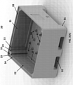
- FIG. 3 provides in (A) a close-up view of a corner section of a container in the absence of a drain canal unit, while in (B) the same section with the drain canal unit in place is shown. It can be seen how the drain canal unit is interlocked with the container walls via the connection between the side surfaces 13 of the unit and slots 33, 34, and further by the connection between the spout 15 and the drain hole 25 in the floor of the container. Circulation channels are formed by slots 23, 24 that are blocked from the body of the container, and by the drain canal unit 10 that provides the barrier between the slots and the body of the container.
- FIG. 4 a top view of the corner section is shown, showing how the drain canal unit can slide into slots 33, 34 and into the drain hole 25 in the container floor, so as to generate circulation channels behind the drain canal unit, between its inner surface 12 (facing the corner when engaged with container) and the corner 35 of the container.
- the corner section of the container can be adapted to provide additional (e.g., three or more) or fewer circulation channels (i.e. a single channel).
- the ghist of this functionality is to provide a closed circulation system, where water is forced under the drain canal unit, into one or more circulation channel in the corner of the container, and into the hollow drain canal unit, from which water is drained (e.g., into adjacent container in a stack of containers).
- the container assembly is adapted to be particularly useful for the depuration of mollusks.
- the system allows for forced circulation of water within such containers.
- the system is adapted to provide uniform circulation and thereby depuration within stacked containers, by allowing water to circulate within each container and be delivered into a below container in a stack.
- FIG. 5 shows a cut-through view of a container assembly as described in the above.
- Mollusks are placed within the container, on top of a drain plate 29.
- Water and fine dirt (sand, grit and the like) is able to pass through holes on the drain plate. Dirt settles on the bottom of the container.
- Water is forced by the water pressure in the container towards corners of the container that contain a drain channel unit, as indicated by dashed arrows. Water is forced to flow through an entry portion of the circulation route under the drain channel unit, into circulation channels in the corner of the container that are formed by the slots 23, 24 and the drain channel unit 10.
- the water path up through the circulation channels leads into the opening 19 of the drain channel unit, from where water flows through the drain canal within the body of the unit and exits via an opening 16 on the spout 15, that sits embedded in the floor of the container.
- FIG. 6 (A) a stack of container assemblies in accordance with the invention is shown.
- the containers are stackable, so that the support members 31 of one sit on ledges 28 on the upper side walls, inwardly from the upper rim of the outer side wall of a below container in a stack. Thereby, the stack is provided with structural stability.
- FIG. 6 (B) there is shown a cross-sectional view of the stack of container assemblies, highlighting the relative position of the containers in the stack and the relative position of the spouts in the stack.
- the opening 16 on the spout 15 that extends from the bottom of a drain canal unit 10 of an assembly is pointed towards the middle of the interior cavity of a below container in a stack of containers.
- water is circulated in the stack so that excess water in a top container is released from its spout and towards the middle of a below container in the stack, and so on.
- there is a continuous circulation of water in the stack with water that is released from the bottom container in the stack being delivered into a drain or the like.
- the drain plate 29 sits on support members 26 that extend from the floor of each container.
- An advantage of the container assembly as described herein is that it can be used in combination with certain prior art containers.
- Containers that can fit within the upper rim and sit on ledges 28 on the upper side walls of the container can in particular be used in combination with the container assembly.
- the container assembly in accordance with the invention can be used in combination with a prior art container by the present applicants, called Saeplast 705 container.
- This prior art container is a stackable depuration container from which depuration water that has been circulated in the container is drained into a below container in a stack.
- the prior art 705 container 50 and the container assembly 20 in accordance with the invention can be used in combination.
- shown in the figures is an assembly showing an alternate stack of containers, with a container assembly according to the invention and a 705 container in between two container assemblies.
- the stack can obviously be extended to include prior art containers 50 and container assemblies 20 in accordance with the invention in any desired order and number.
- the present invention also covers the exact terms, features, values and ranges etc. in case these terms, features, values and ranges etc. are used in conjunction with terms such as about, around, generally, substantially, essentially, at least etc. (i.e., "about 3" shall also cover exactly 3 or “substantially constant” shall also cover exactly constant).
Landscapes
- Life Sciences & Earth Sciences (AREA)
- Environmental Sciences (AREA)
- Marine Sciences & Fisheries (AREA)
- Animal Husbandry (AREA)
- Biodiversity & Conservation Biology (AREA)
- Engineering & Computer Science (AREA)
- Zoology (AREA)
- Wood Science & Technology (AREA)
- Food Science & Technology (AREA)
- Mechanical Engineering (AREA)
- Stackable Containers (AREA)
Claims (6)
- Ensemble récipient comprenant :a. un récipient (20) ayant quatre parois latérales verticales (21, 22) et un fond de récipient, etb. au moins une unité de canal de drainage (10) conçue pour venir en prise de manière opérationnelle et verrouillée avec ledit récipient (20) près d'un coin (35) de celui-ci, l'unité de canal de drainage (10) comprenant une structure creuse formant au moins un canal de drainage qui a au moins une ouverture d'entrée (19) près de son sommet et au moins un bec (15) à son extrémité inférieure, pour une insertion dans et à travers le fond de récipient de sorte que l'au moins une ouverture d'entrée (19), lorsque l'unité de canal de drainage (10) est verrouillée avec le récipient, fasse face à un coin (35) du récipient ;caractérisé en ce que le récipient comprend des fentes (33, 34) sur au moins deux parois latérales intérieures (21, 22) adjacentes, à proximité d'un coin (35) du récipient (20), l'unité de canal de drainage (10) comprenant des parties périphériques (13) conçues pour s'ajuster dans et se verrouiller avec lesdites fentes (33, 34) pour former un joint sensiblement étanche à l'eau lorsqu'il est en prise avec lesdites fentes de sorte que l'unité de canal de drainage (10) soit en prise de manière verrouillée avec deux parois latérales (21, 22) adjacentes du récipient à proximité d'un coin de celui-ci et le récipient étant en outre conçu pour recevoir le bec (15) de l'unité de canal de drainage dans et à travers une ouverture (25) dans le fond de récipient de sorte qu'un joint sensiblement étanche à l'eau est formé entre eux ;et en ce que lorsqu'une unité de canal de drainage (10) vient en prise avec un coin (35) du récipient (20), au moins un canal de circulation (23, 24) entre l'unité de canal de drainage (10) et le coin (35) du récipient est formé ;moyennant quoi l'au moins une unité de canal de drainage (10) et le récipient (20) en prise forment au moins une voie de circulation, chaque voie de circulation ayant une partie d'entrée formée entre l'unité de canal de drainage (10) et le fond de récipient fournie par un espace entre l'unité de canal de drainage et le fond de récipient,une partie de canal de coin comprenant ledit au moins un canal de circulation (23, 24), entre l'unité de canal de drainage (10) et un coin de récipient (35), et une partie de canal de drainage, à l'intérieur de l'unité de canal de drainage ;de sorte que l'eau contenue dans le corps du récipient puisse circuler à travers la partie d'entrée dans et vers le haut à travers la partie de canal de coin et être drainée vers le bas à travers la partie de canal de drainage de l'unité de canal de drainage pour sortir de l'ensemble récipient par l'intermédiaire de son bec (15) .
- Système comprenant une pluralité d'ensembles récipients empilables selon la revendication 1, conçus de sorte que l'eau qui circule à travers la voie de circulation soit drainée dans un récipient inférieur dans une pile desdits récipients.
- Système selon la revendication 2, comprenant pour chaque récipient deux unités de canal de drainage (10) qui sont en prise avec le récipient (20) à proximité de deux coins opposés de celui-ci, formant ainsi deux voies de circulation dans le récipient.
- Système selon l'une quelconque des revendications 2 ou 3,
le bec (15) ayant une ouverture (16) au niveau de son extrémité inférieure qui, lorsqu'elle vient en prise avec le récipient, est orientée à l'opposé du coin du récipient avec lequel l'unité de canal de drainage est en prise, de sorte que l'eau en circulation soit libérée du bec et vers la partie centrale d'un récipient placé en dessous dans une pile de récipients. - Système selon l'une quelconque des revendications 2 à 4,
le récipient (20) comprenant en outre au moins une saillie (27) le long de chaque paroi latérale, les saillies étant conçues pour fournir un support pour le positionnement horizontal d'une plaque de drainage amovible (29) à l'intérieur du récipient. - Système selon la revendication précédente, l'unité de canal de drainage étant en outre conçue pour fournir, lorsqu'elle est en prise avec le récipient, un support pour la plaque de drainage amovible (29) à l'intérieur du récipient.
Applications Claiming Priority (2)
| Application Number | Priority Date | Filing Date | Title |
|---|---|---|---|
| IS050180A IS2993B (is) | 2017-06-01 | 2017-06-01 | Hreinsunarkerfi |
| PCT/IS2018/050005 WO2018220658A1 (fr) | 2017-06-01 | 2018-05-31 | Système d'épuration |
Publications (2)
| Publication Number | Publication Date |
|---|---|
| EP3629718A1 EP3629718A1 (fr) | 2020-04-08 |
| EP3629718B1 true EP3629718B1 (fr) | 2022-02-23 |
Family
ID=71073624
Family Applications (1)
| Application Number | Title | Priority Date | Filing Date |
|---|---|---|---|
| EP18738383.1A Active EP3629718B1 (fr) | 2017-06-01 | 2018-05-31 | Système de dépuration |
Country Status (6)
| Country | Link |
|---|---|
| US (1) | US11528894B2 (fr) |
| EP (1) | EP3629718B1 (fr) |
| CA (1) | CA3065355A1 (fr) |
| ES (1) | ES2912402T3 (fr) |
| IS (1) | IS2993B (fr) |
| WO (1) | WO2018220658A1 (fr) |
Families Citing this family (2)
| Publication number | Priority date | Publication date | Assignee | Title |
|---|---|---|---|---|
| IT202000007180A1 (it) * | 2020-04-03 | 2021-10-03 | Tecniplast Spa | Dispositivo di screening microbiologico, in particolare per la raccolta e concentrazione di materiale organico e inorganico presente in un liquido, e apparecchiatura per l’allevamento di specie animali acquatiche da laboratorio equipaggiata con detto dispositivo |
| CH717584A1 (de) * | 2020-06-29 | 2021-12-30 | Utz Georg Holding Ag | Kunststoffbehälter mit verstärkten Eckpartien. |
Family Cites Families (13)
| Publication number | Priority date | Publication date | Assignee | Title |
|---|---|---|---|---|
| US3641982A (en) * | 1969-04-07 | 1972-02-15 | Nat Shellfish Processors Inc | Bivalvia depuration system |
| US4386700A (en) * | 1981-05-28 | 1983-06-07 | Nestier Corporation | Drain control for multiple stacked containers |
| US4537149A (en) * | 1982-09-14 | 1985-08-27 | Ryan William J | Method and apparatus for cleaning tainted shellfish |
| GB8708053D0 (en) | 1987-04-03 | 1987-05-07 | Brook E M | Shellfish purification system |
| FR2681048A1 (fr) | 1991-09-06 | 1993-03-12 | Stamp | Bac de manutention gerbable et emboitable a evacuation vers l'exterieur de tout liquide qu'il pourrait contenir. |
| US5186121A (en) * | 1991-10-31 | 1993-02-16 | Smith Jr Franklin L | Method of and apparatus for use in the depuration of bivalves |
| US5249548A (en) * | 1992-03-23 | 1993-10-05 | Chi & Associates, Inc. | Shellfish depuration system |
| ES2187326B1 (es) | 2000-10-10 | 2004-11-16 | Mariscos Veiro, S.L. | Dispositivo depurador de moluscos mediante circulacion forzada de agua, y metodo correspondiente. |
| ES1072423Y (es) | 2010-05-07 | 2010-10-06 | Rotogal S L | Contenedor para depuracion de moluscos |
| ITMI20111621A1 (it) | 2011-09-08 | 2013-03-09 | Gvs Spa | Filtro per infusioni medicali a riempimento ottimizzato |
| NL2013090B1 (nl) | 2014-06-30 | 2015-10-14 | Sybe Smit Octrooi B V | Inrichting voor het verwateren van schaal- en/of schelpdieren |
| CA2863692A1 (fr) * | 2014-09-17 | 2016-03-17 | 3283688 Nova Scotia Limited | Contenant pour fruits de mer |
| CH714972A1 (de) * | 2018-05-08 | 2019-11-15 | Utz Georg Holding Ag | Stapelbarer Behälter. |
-
2017
- 2017-06-01 IS IS050180A patent/IS2993B/is unknown
-
2018
- 2018-05-31 ES ES18738383T patent/ES2912402T3/es active Active
- 2018-05-31 US US16/617,800 patent/US11528894B2/en active Active
- 2018-05-31 EP EP18738383.1A patent/EP3629718B1/fr active Active
- 2018-05-31 WO PCT/IS2018/050005 patent/WO2018220658A1/fr not_active Ceased
- 2018-05-31 CA CA3065355A patent/CA3065355A1/fr active Pending
Non-Patent Citations (1)
| Title |
|---|
| None * |
Also Published As
| Publication number | Publication date |
|---|---|
| IS2993B (is) | 2018-03-15 |
| EP3629718A1 (fr) | 2020-04-08 |
| ES2912402T3 (es) | 2022-05-25 |
| WO2018220658A1 (fr) | 2018-12-06 |
| US20200187465A1 (en) | 2020-06-18 |
| CA3065355A1 (fr) | 2018-12-06 |
| US11528894B2 (en) | 2022-12-20 |
Similar Documents
| Publication | Publication Date | Title |
|---|---|---|
| US11528894B2 (en) | Depuration system | |
| CN100527951C (zh) | 一种水族馆过滤器装置 | |
| JP2018191558A (ja) | ペット用給水器およびそのフィルター | |
| KR20200012720A (ko) | 애완동물용 음수기 | |
| WO1999002646A1 (fr) | Systeme de croissance cellulaire autonome | |
| US9750378B2 (en) | Potty | |
| EP0285457A1 (fr) | Procédé et dispositif pour l'élevage de crustacés | |
| CA3232781A1 (fr) | Distributeurs chimiques pour traitement prolonge de l'eau | |
| EP2408512B1 (fr) | Adaptateur pour raccorder un connecteur de récipient à une prise de raccord d'une machine de dialyse | |
| KR101718360B1 (ko) | 수족관 필터링 시스템 | |
| EP2433907A1 (fr) | Dispositif d'assainissement de l'eau contenue dans un bassin | |
| US8932522B2 (en) | Revolutionary toothbrush cleaner | |
| EP3636405B1 (fr) | Réservoir de traitement des eaux usées rotomoulé et son procédé de fabrication | |
| DE60128988T2 (de) | Verfahren zur Tauchbehandlung von Geräten | |
| KR101953792B1 (ko) | 어류 보호장치 | |
| KR101639573B1 (ko) | 수족관용 스키머 | |
| KR101435343B1 (ko) | 약품 분배 투입장치 | |
| EP0506986A1 (fr) | Plateau réversible empilable pour la fabrication des fromages | |
| CA1105786A (fr) | Incubateur d'oeufs de poisson avec separateur d'alevins | |
| AU2011202579B2 (en) | Aquarium filter assembly | |
| CN216764642U (zh) | 一种三层生化仓及微滤生化一体机 | |
| CN217470938U (zh) | 一种烟草种子清洗消毒装置 | |
| JP3816244B2 (ja) | 水浄化フィルター装置枠、水浄化フィルター装着用部材及び水浄化フィルター装置 | |
| EP3211993A1 (fr) | Dispositif pour dépuration de crustacés et de fruits de mer | |
| KR20210002622U (ko) | 청수통과 오수통이 구비된 캠핑용 간이 샤워텐트 |
Legal Events
| Date | Code | Title | Description |
|---|---|---|---|
| STAA | Information on the status of an ep patent application or granted ep patent |
Free format text: STATUS: UNKNOWN |
|
| STAA | Information on the status of an ep patent application or granted ep patent |
Free format text: STATUS: THE INTERNATIONAL PUBLICATION HAS BEEN MADE |
|
| PUAI | Public reference made under article 153(3) epc to a published international application that has entered the european phase |
Free format text: ORIGINAL CODE: 0009012 |
|
| STAA | Information on the status of an ep patent application or granted ep patent |
Free format text: STATUS: REQUEST FOR EXAMINATION WAS MADE |
|
| 17P | Request for examination filed |
Effective date: 20191212 |
|
| AK | Designated contracting states |
Kind code of ref document: A1 Designated state(s): AL AT BE BG CH CY CZ DE DK EE ES FI FR GB GR HR HU IE IS IT LI LT LU LV MC MK MT NL NO PL PT RO RS SE SI SK SM TR |
|
| AX | Request for extension of the european patent |
Extension state: BA ME |
|
| DAV | Request for validation of the european patent (deleted) | ||
| DAX | Request for extension of the european patent (deleted) | ||
| STAA | Information on the status of an ep patent application or granted ep patent |
Free format text: STATUS: EXAMINATION IS IN PROGRESS |
|
| 17Q | First examination report despatched |
Effective date: 20200910 |
|
| GRAP | Despatch of communication of intention to grant a patent |
Free format text: ORIGINAL CODE: EPIDOSNIGR1 |
|
| STAA | Information on the status of an ep patent application or granted ep patent |
Free format text: STATUS: GRANT OF PATENT IS INTENDED |
|
| INTG | Intention to grant announced |
Effective date: 20210910 |
|
| GRAS | Grant fee paid |
Free format text: ORIGINAL CODE: EPIDOSNIGR3 |
|
| GRAA | (expected) grant |
Free format text: ORIGINAL CODE: 0009210 |
|
| STAA | Information on the status of an ep patent application or granted ep patent |
Free format text: STATUS: THE PATENT HAS BEEN GRANTED |
|
| AK | Designated contracting states |
Kind code of ref document: B1 Designated state(s): AL AT BE BG CH CY CZ DE DK EE ES FI FR GB GR HR HU IE IS IT LI LT LU LV MC MK MT NL NO PL PT RO RS SE SI SK SM TR |
|
| REG | Reference to a national code |
Ref country code: GB Ref legal event code: FG4D |
|
| REG | Reference to a national code |
Ref country code: CH Ref legal event code: EP |
|
| REG | Reference to a national code |
Ref country code: DE Ref legal event code: R096 Ref document number: 602018031258 Country of ref document: DE |
|
| REG | Reference to a national code |
Ref country code: AT Ref legal event code: REF Ref document number: 1469750 Country of ref document: AT Kind code of ref document: T Effective date: 20220315 |
|
| REG | Reference to a national code |
Ref country code: IE Ref legal event code: FG4D |
|
| REG | Reference to a national code |
Ref country code: ES Ref legal event code: FG2A Ref document number: 2912402 Country of ref document: ES Kind code of ref document: T3 Effective date: 20220525 |
|
| REG | Reference to a national code |
Ref country code: LT Ref legal event code: MG9D |
|
| REG | Reference to a national code |
Ref country code: NL Ref legal event code: MP Effective date: 20220223 |
|
| REG | Reference to a national code |
Ref country code: AT Ref legal event code: MK05 Ref document number: 1469750 Country of ref document: AT Kind code of ref document: T Effective date: 20220223 |
|
| PG25 | Lapsed in a contracting state [announced via postgrant information from national office to epo] |
Ref country code: SE Free format text: LAPSE BECAUSE OF FAILURE TO SUBMIT A TRANSLATION OF THE DESCRIPTION OR TO PAY THE FEE WITHIN THE PRESCRIBED TIME-LIMIT Effective date: 20220223 Ref country code: RS Free format text: LAPSE BECAUSE OF FAILURE TO SUBMIT A TRANSLATION OF THE DESCRIPTION OR TO PAY THE FEE WITHIN THE PRESCRIBED TIME-LIMIT Effective date: 20220223 Ref country code: PT Free format text: LAPSE BECAUSE OF FAILURE TO SUBMIT A TRANSLATION OF THE DESCRIPTION OR TO PAY THE FEE WITHIN THE PRESCRIBED TIME-LIMIT Effective date: 20220623 Ref country code: NO Free format text: LAPSE BECAUSE OF FAILURE TO SUBMIT A TRANSLATION OF THE DESCRIPTION OR TO PAY THE FEE WITHIN THE PRESCRIBED TIME-LIMIT Effective date: 20220523 Ref country code: NL Free format text: LAPSE BECAUSE OF FAILURE TO SUBMIT A TRANSLATION OF THE DESCRIPTION OR TO PAY THE FEE WITHIN THE PRESCRIBED TIME-LIMIT Effective date: 20220223 Ref country code: LT Free format text: LAPSE BECAUSE OF FAILURE TO SUBMIT A TRANSLATION OF THE DESCRIPTION OR TO PAY THE FEE WITHIN THE PRESCRIBED TIME-LIMIT Effective date: 20220223 Ref country code: HR Free format text: LAPSE BECAUSE OF FAILURE TO SUBMIT A TRANSLATION OF THE DESCRIPTION OR TO PAY THE FEE WITHIN THE PRESCRIBED TIME-LIMIT Effective date: 20220223 Ref country code: BG Free format text: LAPSE BECAUSE OF FAILURE TO SUBMIT A TRANSLATION OF THE DESCRIPTION OR TO PAY THE FEE WITHIN THE PRESCRIBED TIME-LIMIT Effective date: 20220523 |
|
| PG25 | Lapsed in a contracting state [announced via postgrant information from national office to epo] |
Ref country code: PL Free format text: LAPSE BECAUSE OF FAILURE TO SUBMIT A TRANSLATION OF THE DESCRIPTION OR TO PAY THE FEE WITHIN THE PRESCRIBED TIME-LIMIT Effective date: 20220223 Ref country code: LV Free format text: LAPSE BECAUSE OF FAILURE TO SUBMIT A TRANSLATION OF THE DESCRIPTION OR TO PAY THE FEE WITHIN THE PRESCRIBED TIME-LIMIT Effective date: 20220223 Ref country code: GR Free format text: LAPSE BECAUSE OF FAILURE TO SUBMIT A TRANSLATION OF THE DESCRIPTION OR TO PAY THE FEE WITHIN THE PRESCRIBED TIME-LIMIT Effective date: 20220524 Ref country code: FI Free format text: LAPSE BECAUSE OF FAILURE TO SUBMIT A TRANSLATION OF THE DESCRIPTION OR TO PAY THE FEE WITHIN THE PRESCRIBED TIME-LIMIT Effective date: 20220223 Ref country code: AT Free format text: LAPSE BECAUSE OF FAILURE TO SUBMIT A TRANSLATION OF THE DESCRIPTION OR TO PAY THE FEE WITHIN THE PRESCRIBED TIME-LIMIT Effective date: 20220223 |
|
| PG25 | Lapsed in a contracting state [announced via postgrant information from national office to epo] |
Ref country code: IS Free format text: LAPSE BECAUSE OF FAILURE TO SUBMIT A TRANSLATION OF THE DESCRIPTION OR TO PAY THE FEE WITHIN THE PRESCRIBED TIME-LIMIT Effective date: 20220623 |
|
| PG25 | Lapsed in a contracting state [announced via postgrant information from national office to epo] |
Ref country code: SM Free format text: LAPSE BECAUSE OF FAILURE TO SUBMIT A TRANSLATION OF THE DESCRIPTION OR TO PAY THE FEE WITHIN THE PRESCRIBED TIME-LIMIT Effective date: 20220223 Ref country code: SK Free format text: LAPSE BECAUSE OF FAILURE TO SUBMIT A TRANSLATION OF THE DESCRIPTION OR TO PAY THE FEE WITHIN THE PRESCRIBED TIME-LIMIT Effective date: 20220223 Ref country code: RO Free format text: LAPSE BECAUSE OF FAILURE TO SUBMIT A TRANSLATION OF THE DESCRIPTION OR TO PAY THE FEE WITHIN THE PRESCRIBED TIME-LIMIT Effective date: 20220223 Ref country code: EE Free format text: LAPSE BECAUSE OF FAILURE TO SUBMIT A TRANSLATION OF THE DESCRIPTION OR TO PAY THE FEE WITHIN THE PRESCRIBED TIME-LIMIT Effective date: 20220223 Ref country code: DK Free format text: LAPSE BECAUSE OF FAILURE TO SUBMIT A TRANSLATION OF THE DESCRIPTION OR TO PAY THE FEE WITHIN THE PRESCRIBED TIME-LIMIT Effective date: 20220223 Ref country code: CZ Free format text: LAPSE BECAUSE OF FAILURE TO SUBMIT A TRANSLATION OF THE DESCRIPTION OR TO PAY THE FEE WITHIN THE PRESCRIBED TIME-LIMIT Effective date: 20220223 |
|
| REG | Reference to a national code |
Ref country code: DE Ref legal event code: R097 Ref document number: 602018031258 Country of ref document: DE |
|
| PG25 | Lapsed in a contracting state [announced via postgrant information from national office to epo] |
Ref country code: AL Free format text: LAPSE BECAUSE OF FAILURE TO SUBMIT A TRANSLATION OF THE DESCRIPTION OR TO PAY THE FEE WITHIN THE PRESCRIBED TIME-LIMIT Effective date: 20220223 |
|
| REG | Reference to a national code |
Ref country code: DE Ref legal event code: R119 Ref document number: 602018031258 Country of ref document: DE |
|
| PLBE | No opposition filed within time limit |
Free format text: ORIGINAL CODE: 0009261 |
|
| REG | Reference to a national code |
Ref country code: CH Ref legal event code: PL |
|
| STAA | Information on the status of an ep patent application or granted ep patent |
Free format text: STATUS: NO OPPOSITION FILED WITHIN TIME LIMIT |
|
| REG | Reference to a national code |
Ref country code: BE Ref legal event code: MM Effective date: 20220531 |
|
| GBPC | Gb: european patent ceased through non-payment of renewal fee |
Effective date: 20220531 |
|
| PG25 | Lapsed in a contracting state [announced via postgrant information from national office to epo] |
Ref country code: MC Free format text: LAPSE BECAUSE OF FAILURE TO SUBMIT A TRANSLATION OF THE DESCRIPTION OR TO PAY THE FEE WITHIN THE PRESCRIBED TIME-LIMIT Effective date: 20220223 Ref country code: LU Free format text: LAPSE BECAUSE OF NON-PAYMENT OF DUE FEES Effective date: 20220531 Ref country code: LI Free format text: LAPSE BECAUSE OF NON-PAYMENT OF DUE FEES Effective date: 20220531 Ref country code: CH Free format text: LAPSE BECAUSE OF NON-PAYMENT OF DUE FEES Effective date: 20220531 |
|
| 26N | No opposition filed |
Effective date: 20221124 |
|
| PG25 | Lapsed in a contracting state [announced via postgrant information from national office to epo] |
Ref country code: SI Free format text: LAPSE BECAUSE OF FAILURE TO SUBMIT A TRANSLATION OF THE DESCRIPTION OR TO PAY THE FEE WITHIN THE PRESCRIBED TIME-LIMIT Effective date: 20220223 |
|
| PG25 | Lapsed in a contracting state [announced via postgrant information from national office to epo] |
Ref country code: IE Free format text: LAPSE BECAUSE OF NON-PAYMENT OF DUE FEES Effective date: 20220531 Ref country code: FR Free format text: LAPSE BECAUSE OF NON-PAYMENT OF DUE FEES Effective date: 20220531 |
|
| PG25 | Lapsed in a contracting state [announced via postgrant information from national office to epo] |
Ref country code: GB Free format text: LAPSE BECAUSE OF NON-PAYMENT OF DUE FEES Effective date: 20220531 Ref country code: DE Free format text: LAPSE BECAUSE OF NON-PAYMENT OF DUE FEES Effective date: 20221201 Ref country code: BE Free format text: LAPSE BECAUSE OF NON-PAYMENT OF DUE FEES Effective date: 20220531 |
|
| PG25 | Lapsed in a contracting state [announced via postgrant information from national office to epo] |
Ref country code: IT Free format text: LAPSE BECAUSE OF FAILURE TO SUBMIT A TRANSLATION OF THE DESCRIPTION OR TO PAY THE FEE WITHIN THE PRESCRIBED TIME-LIMIT Effective date: 20220223 |
|
| PG25 | Lapsed in a contracting state [announced via postgrant information from national office to epo] |
Ref country code: MK Free format text: LAPSE BECAUSE OF FAILURE TO SUBMIT A TRANSLATION OF THE DESCRIPTION OR TO PAY THE FEE WITHIN THE PRESCRIBED TIME-LIMIT Effective date: 20220223 Ref country code: CY Free format text: LAPSE BECAUSE OF FAILURE TO SUBMIT A TRANSLATION OF THE DESCRIPTION OR TO PAY THE FEE WITHIN THE PRESCRIBED TIME-LIMIT Effective date: 20220223 |
|
| PG25 | Lapsed in a contracting state [announced via postgrant information from national office to epo] |
Ref country code: HU Free format text: LAPSE BECAUSE OF FAILURE TO SUBMIT A TRANSLATION OF THE DESCRIPTION OR TO PAY THE FEE WITHIN THE PRESCRIBED TIME-LIMIT; INVALID AB INITIO Effective date: 20180531 |
|
| PG25 | Lapsed in a contracting state [announced via postgrant information from national office to epo] |
Ref country code: TR Free format text: LAPSE BECAUSE OF FAILURE TO SUBMIT A TRANSLATION OF THE DESCRIPTION OR TO PAY THE FEE WITHIN THE PRESCRIBED TIME-LIMIT Effective date: 20220223 |
|
| PG25 | Lapsed in a contracting state [announced via postgrant information from national office to epo] |
Ref country code: MT Free format text: LAPSE BECAUSE OF FAILURE TO SUBMIT A TRANSLATION OF THE DESCRIPTION OR TO PAY THE FEE WITHIN THE PRESCRIBED TIME-LIMIT Effective date: 20220223 |
|
| PGFP | Annual fee paid to national office [announced via postgrant information from national office to epo] |
Ref country code: ES Payment date: 20250611 Year of fee payment: 8 |