EP3630004B1 - Systèmes pour valvulothérapie cardiaque - Google Patents
Systèmes pour valvulothérapie cardiaque Download PDFInfo
- Publication number
- EP3630004B1 EP3630004B1 EP18805727.7A EP18805727A EP3630004B1 EP 3630004 B1 EP3630004 B1 EP 3630004B1 EP 18805727 A EP18805727 A EP 18805727A EP 3630004 B1 EP3630004 B1 EP 3630004B1
- Authority
- EP
- European Patent Office
- Prior art keywords
- valve
- assembly
- anchor
- anchor assembly
- valve assembly
- Prior art date
- Legal status (The legal status is an assumption and is not a legal conclusion. Google has not performed a legal analysis and makes no representation as to the accuracy of the status listed.)
- Active
Links
Images




Classifications
-
- A—HUMAN NECESSITIES
- A61—MEDICAL OR VETERINARY SCIENCE; HYGIENE
- A61F—FILTERS IMPLANTABLE INTO BLOOD VESSELS; PROSTHESES; DEVICES PROVIDING PATENCY TO, OR PREVENTING COLLAPSING OF, TUBULAR STRUCTURES OF THE BODY, e.g. STENTS; ORTHOPAEDIC, NURSING OR CONTRACEPTIVE DEVICES; FOMENTATION; TREATMENT OR PROTECTION OF EYES OR EARS; BANDAGES, DRESSINGS OR ABSORBENT PADS; FIRST-AID KITS
- A61F2/00—Filters implantable into blood vessels; Prostheses, i.e. artificial substitutes or replacements for parts of the body; Appliances for connecting them with the body; Devices providing patency to, or preventing collapsing of, tubular structures of the body, e.g. stents
- A61F2/02—Prostheses implantable into the body
- A61F2/24—Heart valves ; Vascular valves, e.g. venous valves; Heart implants, e.g. passive devices for improving the function of the native valve or the heart muscle; Transmyocardial revascularisation [TMR] devices; Valves implantable in the body
- A61F2/2427—Devices for manipulating or deploying heart valves during implantation
- A61F2/2439—Expansion controlled by filaments
-
- A—HUMAN NECESSITIES
- A61—MEDICAL OR VETERINARY SCIENCE; HYGIENE
- A61F—FILTERS IMPLANTABLE INTO BLOOD VESSELS; PROSTHESES; DEVICES PROVIDING PATENCY TO, OR PREVENTING COLLAPSING OF, TUBULAR STRUCTURES OF THE BODY, e.g. STENTS; ORTHOPAEDIC, NURSING OR CONTRACEPTIVE DEVICES; FOMENTATION; TREATMENT OR PROTECTION OF EYES OR EARS; BANDAGES, DRESSINGS OR ABSORBENT PADS; FIRST-AID KITS
- A61F2/00—Filters implantable into blood vessels; Prostheses, i.e. artificial substitutes or replacements for parts of the body; Appliances for connecting them with the body; Devices providing patency to, or preventing collapsing of, tubular structures of the body, e.g. stents
- A61F2/02—Prostheses implantable into the body
- A61F2/24—Heart valves ; Vascular valves, e.g. venous valves; Heart implants, e.g. passive devices for improving the function of the native valve or the heart muscle; Transmyocardial revascularisation [TMR] devices; Valves implantable in the body
- A61F2/2409—Support rings therefor, e.g. for connecting valves to tissue
-
- A—HUMAN NECESSITIES
- A61—MEDICAL OR VETERINARY SCIENCE; HYGIENE
- A61F—FILTERS IMPLANTABLE INTO BLOOD VESSELS; PROSTHESES; DEVICES PROVIDING PATENCY TO, OR PREVENTING COLLAPSING OF, TUBULAR STRUCTURES OF THE BODY, e.g. STENTS; ORTHOPAEDIC, NURSING OR CONTRACEPTIVE DEVICES; FOMENTATION; TREATMENT OR PROTECTION OF EYES OR EARS; BANDAGES, DRESSINGS OR ABSORBENT PADS; FIRST-AID KITS
- A61F2/00—Filters implantable into blood vessels; Prostheses, i.e. artificial substitutes or replacements for parts of the body; Appliances for connecting them with the body; Devices providing patency to, or preventing collapsing of, tubular structures of the body, e.g. stents
- A61F2/02—Prostheses implantable into the body
- A61F2/24—Heart valves ; Vascular valves, e.g. venous valves; Heart implants, e.g. passive devices for improving the function of the native valve or the heart muscle; Transmyocardial revascularisation [TMR] devices; Valves implantable in the body
- A61F2/2412—Heart valves ; Vascular valves, e.g. venous valves; Heart implants, e.g. passive devices for improving the function of the native valve or the heart muscle; Transmyocardial revascularisation [TMR] devices; Valves implantable in the body with soft flexible valve members, e.g. tissue valves shaped like natural valves
- A61F2/2418—Scaffolds therefor, e.g. support stents
-
- A—HUMAN NECESSITIES
- A61—MEDICAL OR VETERINARY SCIENCE; HYGIENE
- A61F—FILTERS IMPLANTABLE INTO BLOOD VESSELS; PROSTHESES; DEVICES PROVIDING PATENCY TO, OR PREVENTING COLLAPSING OF, TUBULAR STRUCTURES OF THE BODY, e.g. STENTS; ORTHOPAEDIC, NURSING OR CONTRACEPTIVE DEVICES; FOMENTATION; TREATMENT OR PROTECTION OF EYES OR EARS; BANDAGES, DRESSINGS OR ABSORBENT PADS; FIRST-AID KITS
- A61F2/00—Filters implantable into blood vessels; Prostheses, i.e. artificial substitutes or replacements for parts of the body; Appliances for connecting them with the body; Devices providing patency to, or preventing collapsing of, tubular structures of the body, e.g. stents
- A61F2/02—Prostheses implantable into the body
- A61F2/24—Heart valves ; Vascular valves, e.g. venous valves; Heart implants, e.g. passive devices for improving the function of the native valve or the heart muscle; Transmyocardial revascularisation [TMR] devices; Valves implantable in the body
- A61F2/2427—Devices for manipulating or deploying heart valves during implantation
- A61F2/2436—Deployment by retracting a sheath
-
- A—HUMAN NECESSITIES
- A61—MEDICAL OR VETERINARY SCIENCE; HYGIENE
- A61F—FILTERS IMPLANTABLE INTO BLOOD VESSELS; PROSTHESES; DEVICES PROVIDING PATENCY TO, OR PREVENTING COLLAPSING OF, TUBULAR STRUCTURES OF THE BODY, e.g. STENTS; ORTHOPAEDIC, NURSING OR CONTRACEPTIVE DEVICES; FOMENTATION; TREATMENT OR PROTECTION OF EYES OR EARS; BANDAGES, DRESSINGS OR ABSORBENT PADS; FIRST-AID KITS
- A61F2220/00—Fixations or connections for prostheses classified in groups A61F2/00 - A61F2/26 or A61F2/82 or A61F9/00 or A61F11/00 or subgroups thereof
- A61F2220/0008—Fixation appliances for connecting prostheses to the body
-
- A—HUMAN NECESSITIES
- A61—MEDICAL OR VETERINARY SCIENCE; HYGIENE
- A61F—FILTERS IMPLANTABLE INTO BLOOD VESSELS; PROSTHESES; DEVICES PROVIDING PATENCY TO, OR PREVENTING COLLAPSING OF, TUBULAR STRUCTURES OF THE BODY, e.g. STENTS; ORTHOPAEDIC, NURSING OR CONTRACEPTIVE DEVICES; FOMENTATION; TREATMENT OR PROTECTION OF EYES OR EARS; BANDAGES, DRESSINGS OR ABSORBENT PADS; FIRST-AID KITS
- A61F2220/00—Fixations or connections for prostheses classified in groups A61F2/00 - A61F2/26 or A61F2/82 or A61F9/00 or A61F11/00 or subgroups thereof
- A61F2220/0025—Connections or couplings between prosthetic parts, e.g. between modular parts; Connecting elements
- A61F2220/0033—Connections or couplings between prosthetic parts, e.g. between modular parts; Connecting elements made by longitudinally pushing a protrusion into a complementary-shaped recess, e.g. held by friction fit
-
- A—HUMAN NECESSITIES
- A61—MEDICAL OR VETERINARY SCIENCE; HYGIENE
- A61F—FILTERS IMPLANTABLE INTO BLOOD VESSELS; PROSTHESES; DEVICES PROVIDING PATENCY TO, OR PREVENTING COLLAPSING OF, TUBULAR STRUCTURES OF THE BODY, e.g. STENTS; ORTHOPAEDIC, NURSING OR CONTRACEPTIVE DEVICES; FOMENTATION; TREATMENT OR PROTECTION OF EYES OR EARS; BANDAGES, DRESSINGS OR ABSORBENT PADS; FIRST-AID KITS
- A61F2230/00—Geometry of prostheses classified in groups A61F2/00 - A61F2/26 or A61F2/82 or A61F9/00 or A61F11/00 or subgroups thereof
- A61F2230/0002—Two-dimensional shapes, e.g. cross-sections
- A61F2230/0028—Shapes in the form of latin or greek characters
- A61F2230/0034—D-shaped
-
- A—HUMAN NECESSITIES
- A61—MEDICAL OR VETERINARY SCIENCE; HYGIENE
- A61F—FILTERS IMPLANTABLE INTO BLOOD VESSELS; PROSTHESES; DEVICES PROVIDING PATENCY TO, OR PREVENTING COLLAPSING OF, TUBULAR STRUCTURES OF THE BODY, e.g. STENTS; ORTHOPAEDIC, NURSING OR CONTRACEPTIVE DEVICES; FOMENTATION; TREATMENT OR PROTECTION OF EYES OR EARS; BANDAGES, DRESSINGS OR ABSORBENT PADS; FIRST-AID KITS
- A61F2230/00—Geometry of prostheses classified in groups A61F2/00 - A61F2/26 or A61F2/82 or A61F9/00 or A61F11/00 or subgroups thereof
- A61F2230/0002—Two-dimensional shapes, e.g. cross-sections
- A61F2230/0028—Shapes in the form of latin or greek characters
- A61F2230/0039—H-shaped
-
- A—HUMAN NECESSITIES
- A61—MEDICAL OR VETERINARY SCIENCE; HYGIENE
- A61F—FILTERS IMPLANTABLE INTO BLOOD VESSELS; PROSTHESES; DEVICES PROVIDING PATENCY TO, OR PREVENTING COLLAPSING OF, TUBULAR STRUCTURES OF THE BODY, e.g. STENTS; ORTHOPAEDIC, NURSING OR CONTRACEPTIVE DEVICES; FOMENTATION; TREATMENT OR PROTECTION OF EYES OR EARS; BANDAGES, DRESSINGS OR ABSORBENT PADS; FIRST-AID KITS
- A61F2230/00—Geometry of prostheses classified in groups A61F2/00 - A61F2/26 or A61F2/82 or A61F9/00 or A61F11/00 or subgroups thereof
- A61F2230/0002—Two-dimensional shapes, e.g. cross-sections
- A61F2230/0028—Shapes in the form of latin or greek characters
- A61F2230/005—Rosette-shaped, e.g. star-shaped
-
- A—HUMAN NECESSITIES
- A61—MEDICAL OR VETERINARY SCIENCE; HYGIENE
- A61F—FILTERS IMPLANTABLE INTO BLOOD VESSELS; PROSTHESES; DEVICES PROVIDING PATENCY TO, OR PREVENTING COLLAPSING OF, TUBULAR STRUCTURES OF THE BODY, e.g. STENTS; ORTHOPAEDIC, NURSING OR CONTRACEPTIVE DEVICES; FOMENTATION; TREATMENT OR PROTECTION OF EYES OR EARS; BANDAGES, DRESSINGS OR ABSORBENT PADS; FIRST-AID KITS
- A61F2230/00—Geometry of prostheses classified in groups A61F2/00 - A61F2/26 or A61F2/82 or A61F9/00 or A61F11/00 or subgroups thereof
- A61F2230/0002—Two-dimensional shapes, e.g. cross-sections
- A61F2230/0028—Shapes in the form of latin or greek characters
- A61F2230/0054—V-shaped
-
- A—HUMAN NECESSITIES
- A61—MEDICAL OR VETERINARY SCIENCE; HYGIENE
- A61F—FILTERS IMPLANTABLE INTO BLOOD VESSELS; PROSTHESES; DEVICES PROVIDING PATENCY TO, OR PREVENTING COLLAPSING OF, TUBULAR STRUCTURES OF THE BODY, e.g. STENTS; ORTHOPAEDIC, NURSING OR CONTRACEPTIVE DEVICES; FOMENTATION; TREATMENT OR PROTECTION OF EYES OR EARS; BANDAGES, DRESSINGS OR ABSORBENT PADS; FIRST-AID KITS
- A61F2250/00—Special features of prostheses classified in groups A61F2/00 - A61F2/26 or A61F2/82 or A61F9/00 or A61F11/00 or subgroups thereof
- A61F2250/0014—Special features of prostheses classified in groups A61F2/00 - A61F2/26 or A61F2/82 or A61F9/00 or A61F11/00 or subgroups thereof having different values of a given property or geometrical feature, e.g. mechanical property or material property, at different locations within the same prosthesis
- A61F2250/0039—Special features of prostheses classified in groups A61F2/00 - A61F2/26 or A61F2/82 or A61F9/00 or A61F11/00 or subgroups thereof having different values of a given property or geometrical feature, e.g. mechanical property or material property, at different locations within the same prosthesis differing in diameter
-
- A—HUMAN NECESSITIES
- A61—MEDICAL OR VETERINARY SCIENCE; HYGIENE
- A61F—FILTERS IMPLANTABLE INTO BLOOD VESSELS; PROSTHESES; DEVICES PROVIDING PATENCY TO, OR PREVENTING COLLAPSING OF, TUBULAR STRUCTURES OF THE BODY, e.g. STENTS; ORTHOPAEDIC, NURSING OR CONTRACEPTIVE DEVICES; FOMENTATION; TREATMENT OR PROTECTION OF EYES OR EARS; BANDAGES, DRESSINGS OR ABSORBENT PADS; FIRST-AID KITS
- A61F2250/00—Special features of prostheses classified in groups A61F2/00 - A61F2/26 or A61F2/82 or A61F9/00 or A61F11/00 or subgroups thereof
- A61F2250/0058—Additional features; Implant or prostheses properties not otherwise provided for
- A61F2250/006—Additional features; Implant or prostheses properties not otherwise provided for modular
- A61F2250/0063—Nested prosthetic parts
Definitions
- This document relates to prosthetic heart valves, such as prosthetic mitral valves that can be implanted using transcatheter techniques.
- This document also relates to systems and methods for implanting a two-part prosthetic heart valve that is arranged in a nested configuration during the transcatheter delivery and deployment processes.
- the invention relates to a transcatheter mitral valve replacement system for a heart as defined in claim 1. Particular embodiments are defined in dependent claims 2 - 10.
- MR mitral regurgitation
- therapies for MR reduction can have the effect of reducing the elevated pressures in the left atrium and pulmonary vasculature reducing pulmonary edema (congestion) and shortness of breath symptomatology.
- Such therapies for MR reduction may also have a positive effect on the filling profile of the left ventricle (LV) and the restrictive LV physiology that can result with MR.
- LV left ventricle
- pathophysiologic issues indicate the potential benefits of MR therapy, but also indicate the complexity of the system and the need for a therapy to focus beyond the MR level or grade.
- percutaneous access procedures in which a medical device is introduced through a patient's skin and into a patient's blood vessel, such an access can be used to introduce devices into the patient without the use of large cut downs, which can be painful and in some cases can hemorrhage or become infected.
- a percutaneous access generally employs only a small hole through the skin, which subsequently seals relatively easily, and heals quickly in comparison to a surgical cut down.
- US 2010/249915 A1 discloses a two-part prosthetic mitral valve delivered by a catheter having an outer sheath.
- prosthetic heart valves such as prosthetic mitral valves, that interface and anchor in cooperation with the anatomical structures of a native mitral valve.
- this document describes systems and methods for implanting a two-part prosthetic heart valve in which two expandable components are arranged in a nested configuration during both the transcatheter delivery process and the deployment process within the heart.
- the invention is directed to a transcatheter mitral valve replacement system for a heart.
- the transcatheter mitral valve replacement system includes a delivery sheath having a distal end portion insertable into a left atrium, a delivery catheter slidably disposed within the delivery sheath, and a two-part prosthetic mitral valve coupled to the delivery catheter by one or more control wires.
- the two-part prosthetic mitral valve is configured to be disposed within the delivery sheath in a radially compressed condition and to radially self-expand when the two-part prosthetic mitral valve is outside of the delivery sheath and is unconstrained by the one or more control wires.
- the two-part prosthetic mitral valve includes a valve assembly including an expandable valve frame and a tri-leaflet occluder and an anchor assembly separately expandable from the valve assembly and defining an interior space within which the valve assembly is nested while the two-part prosthetic mitral valve is within the delivery sheath for simultaneous deployment from the delivery sheath.
- the system also includes a pusher catheter slidably disposed within the deliver catheter and releasably coupled to the anchor assembly.
- the one or more control wires may include: a first control wire coupled to a proximal end portion of the anchor assembly; a second control wire coupled to a mid-body portion of the anchor assembly; a third control wire coupled to a proximal end portion of the valve assembly; and a fourth control wire coupled to a distal end portion of the valve assembly.
- the one or more control wires may include: a first control wire coupled to a proximal end portion of the anchor assembly; a second control wire coupled to a proximal end portion of the valve assembly; and a third control wire coupled to a distal end portion of the valve assembly.
- the one or more control wires may include: a first control wire coupled to a proximal end portion of the anchor assembly and to a proximal end portion of the valve assembly; a second control wire coupled to a mid-body portion of the anchor assembly; and a third control wire coupled to a distal end portion of the valve assembly.
- the one or more control wires may include: a first control wire coupled to a proximal end portion of the anchor assembly and to a proximal end portion of the valve assembly; and a second control wire coupled to a distal end portion of the valve assembly.
- a mid-body portion of the valve assembly may have a D-shaped cross-sectional shape.
- the anchor assembly may include four feet configured to reside within a sub-annular gutter of a native mitral valve when the two-part prosthetic mitral valve is implanted within the heart.
- the anchor assembly may include supra-annular features including an undulating supra-annular ring that defines an end of the interior space and atrial holding features configured to contact supra-annular tissue surfaces above an annulus of the mitral valve.
- the system may also include a deployment control system coupled to proximal ends of the delivery sheath and the delivery catheter. The deployment control system may include mechanisms for adjusting tension applied to the one or more control wires.
- this disclosure is directed to a method for deploying a transcatheter prosthetic mitral valve system within a native mitral valve of a patient.
- the method may include: navigating a delivery sheath within the vasculature of the patient such that a distal end portion of the delivery sheath is positioned within a left atrium of the patient.
- the delivery sheath contains a two-part prosthetic mitral valve in a radially compressed condition and comprising: a valve assembly including an expandable valve frame and a tri-leaflet occluder; and an anchor assembly including an expandable anchor frame separate from the expandable valve frame of the valve assembly and defining an interior space within which the valve assembly is disposed while the two-part prosthetic mitral valve is within the delivery sheath.
- the method may also include expressing, in the left atrium, the two-part prosthetic mitral valve.
- a delivery catheter is releasably engaged with the two-part prosthetic mitral valve using one or more control wires.
- the valve assembly remains disposed within the interior space defined by the anchor assembly during and after the expressing.
- the method may also include engaging the anchor assembly with the native mitral valve.
- the anchor assembly is in a radially expanded condition while engaged with the native mitral valve.
- the method may also include, after the engaging the anchor assembly in in the radially expanded condition, expanding the valve assembly within the interior space to couple the valve assembly to the anchor assembly.
- Such a method for deploying a transcatheter prosthetic mitral valve system within a native mitral valve of a patient may optionally include one or more of the following features.
- the expanding the valve assembly may include relieving tension of the one or more control wires to allow the valve assembly to self-expand.
- the engaging the anchor assembly with the native mitral valve may include relieving tension of the one or more control wires to allow the anchor assembly to self-expand and positioning four feet of the anchor assembly within a sub-annular gutter of the native mitral valve.
- the engaging the anchor assembly with the native mitral valve may also include positioning atrial holding features of the anchor assembly adjacent to supra-annular tissue surfaces above an annulus of the mitral valve.
- this disclosure is directed to a two-part prosthetic heart valve having two separately expandable components arranged in a nested configuration for transcatheter delivery to a heart.
- the two-part prosthetic heart valve includes an anchor assembly including an expandable anchor frame defining an interior space and defining a plurality of sub-annular anchor feet.
- the anchor assembly is expandable from a compressed anchor delivery configuration to an expanded anchor deployment configuration in which the sub-annular anchor feet are sized and shaped to engage along an underside of a mitral valve annulus.
- the two-part prosthetic heart valve also includes a valve assembly including an expandable valve frame that is separately expandable from the expandable anchor frame.
- the valve assembly is nested within the interior space of the expandable anchor frame while the anchor assembly is in the compressed anchor delivery configuration.
- the expandable valve frame defines a central orifice and a leaflet occluder positioned within the central orifice.
- the valve assembly is expandable from a compressed valve delivery configuration to an expanded valve deployment configuration after the anchor assembly is in the expanded anchor deployment configuration.
- Such a two-part prosthetic heart valve may optionally include one or more of the following optional features.
- the plurality of sub-annular anchor feet of the anchor assembly may include four anchor feet configured to reside within a sub-annular gutter of a native mitral valve when the anchor assembly is in the expanded anchor deployment configuration.
- the anchor assembly may include a supra-annular element including an undulating supra-annular ring that defines an uppermost end of the interior space and atrial holding elements configured to contact supra-annular tissue above the mitral valve annulus.
- this disclosure is directed to a method of deploying a two-part prosthetic heart valve having two separately expandable components arranged in a nested configuration during transcatheter delivery to a heart.
- the method includes delivering a valve assembly having an expandable valve frame to the heart while nested within a separately expandable anchor frame of an anchor assembly in a compressed anchor delivery configuration, and contemporaneously deploying the valve assembly and the anchor assembly into the heart while the valve assembly is nested within the anchor assembly.
- Such a method of deploying a two-part prosthetic heart valve having two separately expandable components arranged in a nested configuration during transcatheter delivery to a heart may optionally include one or more of the following features.
- the method may also include expanding the anchor assembly from the compressed anchor delivery configuration to an expanded anchor deployment configuration in which sub-annular anchor feet of the anchor assembly engage along an underside of a mitral valve annulus.
- the method may also include, after expanding the anchor assembly to the expanded anchor deployment configuration, expanding the valve assembly from a compressed valve configuration to an expanded valve deployment configuration in which the valve assembly mechanically mates to an interior region of the anchor assembly.
- Some or all of the embodiments described herein may provide one or more of the following advantages.
- various medical conditions such as heart valve conditions
- Such minimally invasive techniques can tend to reduce recovery times, patient discomfort, and treatment costs.
- the devices, systems, and methods described herein facilitate the implantation of a two-part prosthetic heart valve in which two expandable components are arranged in a nested configuration during the transcatheter delivery and deployment processes. Accordingly, the time to complete the procedure is advantageously minimalized. This can result in reduced time in the operating room, lessened patient risks, and lower procedural costs.
- the transcatheter prosthetic heart valve and deployment systems described herein are configured to facilitate accurate control of the prosthetic valve components during the delivery and deployment process.
- one or more control wires are coupled to end portions or middle portions of the prosthetic valve components in a manner that allows for isolated, accurate movements of each degree of freedom associated with the catheters and prosthetic valve components. Accordingly, relatively complex catheter and/or valve component movements are facilitated in an accurately controllable and user-convenient manner.
- transcatheter implant procedures can be performed with enhanced patient safety and treatment efficacy using the devices, systems, and methods described herein.
- some embodiments of the prosthetic mitral valve and deployment systems described herein can be used in a completely percutaneous/transcatheter mitral replacement procedure that is streamlined, safe, reliable, and repeatable by surgeons and/or interventional cardiologists of a variety of different skill levels.
- the two-part prosthetic mitral valve can optionally include two different expandable components (e.g., an anchor assembly and a valve assembly) that are delivered to the implantation site in a nested arrangement.
- the first component e.g., the anchor assembly including a first expandable frame
- the second component e.g., the valve assembly including a second expandable frame
- the first component can be configured to engage with the heart tissue that is at or proximate to the annulus of the native mitral valve
- the second component e.g., the valve assembly including a second expandable frame
- the second component can be configured to provide a seal interface with native valve leaflets of the mitral valve.
- prosthetic heart valves such as prosthetic mitral valves, that interface and anchor in cooperation with the anatomical structures of a native mitral valve.
- this document describes systems and methods for implanting a two-part prosthetic heart valve in which two expandable components are arranged in a nested configuration during the transcatheter delivery and deployment processes.
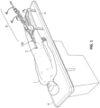
- a two-part prosthetic mitral valve 400 can be deployed in a patient 1 using a transcatheter delivery system 100.
- the prosthetic mitral valve 400 is percutaneously deployed via a femoral or iliac vein through a groin opening/incision 2 in the patient 1 in a minimally invasive fashion.
- a deployment control system 6 is used to initiate and/or control the movements of various components of the transcatheter delivery system 100, and of the prosthetic mitral valve 400, as described further below.
- the two-part prosthetic mitral valve 400 can be delivered to and implanted in the heart 10 using a percutaneous, or minimally invasive, technique via the venous or arterial system (without open-chest or open-heart surgery).
- the transcatheter delivery system 100 and prosthetic mitral valve 400 are used in conjunction with one or more imaging modalities such as x-ray fluoroscopy, echocardiography, magnetic resonance imaging, computed tomography (CT), and the like.
- imaging modalities such as x-ray fluoroscopy, echocardiography, magnetic resonance imaging, computed tomography (CT), and the like.
- CT computed tomography
- various components of the transcatheter delivery system 100 and/or the prosthetic mitral valve 400 can include one or more features to enhance their visibilities under imaging modalities, such as radio-opaque markers.
- the guidewire 110 is installed into the heart 10 prior to the other components of the delivery system 100.
- the guidewire 110 has a diameter of about 0.035 inches (about 0.89 mm).
- the guidewire 110 has a diameter in a range of about 0.032 inches to about 0.038 inches (about 0.8 mm to about 0.97 mm).
- the guidewire 110 has a diameter smaller than 0.032 inches (about 0.80 mm) or larger than 0.038 inches (about 0.97 mm).
- the guidewire 110 is made of materials such as, but not limited to, nitinol, stainless steel, high-tensile-strength stainless steel, and the like, and combinations thereof.
- the guidewire 110 may include various tip designs (e.g., J-tip, straight tip, etc.), tapers, coatings, covers, radiopaque (RO) markers, and other features.
- the guidewire 110 has one or more portions with differing lateral stiffnesses, column strengths, lubricity, and/or other physical properties in comparison to other portions of the guidewire 110.
- the guidewire 110 is percutaneously inserted into a femoral vein of the patient 1.
- the guidewire 110 is routed to the inferior vena cava and into the right atrium.
- the guidewire 110 is routed into the left atrium 16.
- the guidewire 110 is routed through the mitral valve 17 and into the left ventricle 18. This is preferably performed without entangling the guidewire 110 with the chordae tendineae 40 of the mitral valve 17.
- the guidewire 110 can be installed into the heart 10 along other anatomical pathways.
- the guidewire 110 thereafter serves as a rail over which other components of the delivery system 100 are passed.
- the transcatheter delivery system 100 facilitates implantation of the two-part prosthetic mitral valve 400 in the heart 10 while the heart 10 is beating.
- the transcatheter prosthetic heart valve delivery system 100 can be navigated through the venous vasculature of the patient 1, and through the atrial septum (e.g., a trans-septal puncture of the fossa ovalis or other portion of the atrial septum), to obtain access to the left atrium 16 of the patient's heart 10.
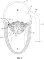
- FIG. 2 shows the two-part prosthetic mitral valve 400 fully deployed within the native mitral valve such that the prosthetic mitral valve 400 is performing the mitral valve function.
- the example two-part prosthetic mitral valve 400 includes an anchor assembly 200 (including a first expandable frame structure) and a separate valve assembly 300 (including a second expandable frame structure).
- the valve assembly 300 is sized and shaped to releasably mount to the framework of the anchor assembly 200.
- the anchor assembly 200 includes four anchor feet: a lateral anterior foot 220a, a lateral posterior foot 220b, a medial posterior foot 220c, and a medial anterior foot 220d. In some embodiments, fewer or more anchor feet may be included (e.g., two, three, five, six, or more than six). In some embodiments, the anchor feet 220a, 220b, 220c, and 220d are portions of the anchor assembly 200 that are configured for contact with a sub-annular gutter 19 of the native mitral valve 17, without penetrating tissue of the native mitral valve 17. Accordingly, the anchor feet 220a, 220b, 220c, and 220d have atraumatic surfaces that are generally comparable to feet. However, in some embodiments one or more of the anchor feet 220a, 220b, 220c, and 220d are configured to penetrate tissue and may have anchor features such as barbs, coils, hooks, and the like.
- anchor assembly 200 is merely one non-limiting example of the anchor assemblies included within the scope of this disclosure.
- the anchor assembly 200 includes supra-annular structures and sub-annular structures.
- the sub-annular structures of the anchor assembly 200 can include the aforementioned anchor feet 220a, 220b, 220c, and 220d, a systolic anterior motion (SAM) containment member 212, and a hub 210.
- the SAM containment member 212 is designed to inhibit the incursion of an anterior leaflet of the native mitral valve into the LVOT during systole, which might otherwise cause LVOT obstruction or the creation of high LVOT pressure gradients.
- the hub 210 functions as a connection structure for the delivery system 100.
- the hub 210 can function as a stabilizing structural component from which a lateral anterior sub-annular support arm 230a and a medial anterior sub-annular support arm 230d extend to the anchor feet 220a and 220d respectively.
- a lateral posterior sub-annular support arm 230b extends from the lateral anterior sub-annular support arm 230a to the lateral posterior foot 220b.
- a medial posterior sub-annular support arm 230c extends from the medial anterior sub-annular support arm 230d to the medial posterior foot 220c.
- the supra-annular structures of the anchor assembly 200 include: a lateral anterior atrial holding feature 240a, a posterior atrial holding feature 240b, and a medial anterior atrial holding feature 240c; a lateral anterior anchor arch 250a, a posterior anchor arch 250b, and a medial anterior anchor arch 250c.
- the lateral anterior anchor arch 250a, the posterior anchor arch 250b, and the medial anterior anchor arch 250c are joined with each other to form an undulating supra-annular ring 250 that acts as a supra-annular structural element for the anchor assembly 200.
- the supra-annular ring 250 also defines an opening to a space within the interior of the anchor assembly 200 that is configured to receive and engage with the valve assembly 300.
- the atrial holding features 240a, 240b, and 240c are configured to contact the shelf-like supra-annular tissue surface above the mitral valve annulus, and to thereby stabilize the anchor assembly 200 in supra-annular areas and to provide migration resistance in the direction towards the left ventricle 18.
- the valve assembly 300 includes a proximal end portion 302 and a distal end portion 303.
- the proximal end portion 302 When the valve assembly 300 is implanted in a native mitral valve, the proximal end portion 302 is located supra-annular (in the left atrium 16) and the distal end portion 303 is located sub-annular (in the left ventricle 18).
- the proximal end portion 302 defines the generally circular entrance orifice of the valve assembly 300.
- At least three prosthetic valve leaflets are located within the valve assembly 300.
- valve assembly 300 is merely one non-limiting example of the valve assemblies included within the scope of this disclosure.
- the valve assembly 300 generally flares outward along a distal direction.
- the distal end portion 303 is flared outward in comparison to the proximal end portion 302.
- the proximal end portion 302 defines a smaller outer profile in comparison to the distal end portion 303.
- some regions of the distal end portion 303 bow inwardly. Such inward bowing can serve to mitigate LVOT obstructions and enhance sealing in some cases.
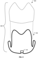
- the periphery of the distal end portion 303 is generally D-shaped in cross-section.
- the D-shaped periphery of the distal end portion 303 provides the valve assembly 300 with an advantageous outer profile for interfacing and sealing with the native mitral valve.
- sealing is attained by coaptation between the D-shaped periphery of the distal end portion 303 and the leaflets of the native mitral valve.
- the proximal end portion 302 of the valve assembly 300 includes three atrial leaflet arches 310a, 310b, and 310c that together define an undulating ring at the proximal end portion 302.
- Each of the leaflet arches 310a, 310b, and 310c includes an apex having one or more holes 312a, 312b, and 312c respectively.
- the holes 312a, 312b, and 312c are used for coupling the proximal end of the valve assembly 300 to a delivery catheter using a proximal control wire.
- one or more of the holes 312a, 312b, and 312c are used for containing radiopaque material.
- valve assembly 300 includes three leaflets (not visible) that perform the occluding function of the prosthetic mitral valve 400.
- the cusps of the three leaflets are fixed to the three atrial leaflet arches 310a, 310b, and 310c, and to three commissural posts (not visible) that each extend distally from the intersections of the three leaflet arches 310a, 310b, and 310c.
- the three commissural posts are disposed at about 120° apart from each other.
- the commissural posts each have a series of holes that can be used for attachment of the prosthetic valve leaflets, such as by suturing.
- the three leaflet arches 310a, 310b, and 310c and the three commissural posts are areas on the valve assembly 300 to which the three prosthetic valve leaflets become attached to comprise a tri-leaflet occluder.
- the valve assembly 300 provides a proven and advantageous frame configuration for the tri-leaflet occluder.
- the tri-leaflet occluder of the valve assembly 300 provides open flow during diastole and occlusion of flow during systole.
- the free edges of the three leaflets can seal by coaptation with each other during systole and open during diastole.
- the three leaflets can be comprised of natural or synthetic materials.
- the three leaflets can be comprised of any of the materials described below in reference to the coverings 270 and/or 340, including the natural tissues such as, but not limited to, bovine, porcine, ovine, or equine pericardium.
- the tissues are chemically cross-linked using glutaraldehyde, formaldehyde, or triglycidyl amine solution, or other suitable crosslinking agents.
- the leaflets have a thickness in a range of about 0.005" to about 0.020" (about 0.13 mm to about 0.51 mm), or about 0.008" to about 0.012" (about 0.20 mm to about 0.31 mm).
- the leaflets have a thickness that is less than about 0.005" (about 0.13 mm) or greater than about 0.020" (about 0.51 mm).
- the occluding function of the prosthetic mitral valve 400 can be performed using configurations other than a tri-leaflet occluder.
- bi-leaflet, quad-leaflet, or mechanical valve constructs can be used in some embodiments.
- the anchor assembly 200 includes a covering material 270 disposed on one or more portions of the anchor assembly 200 and/or the valve assembly 300 includes a covering material 340 disposed on one or more portion of the valve assembly 300.
- the covering materials 270/340 can provide various benefits. For example, in some implementations the covering materials 270/340 can facilitate tissue ingrowth and/or endothelialization, thereby enhancing the migration resistance of the anchor assembly 200 and/or valve assembly 300, and preventing thrombus formation on blood contact elements. In another example, as described further below, the covering materials 270/340 can be used to facilitate coupling between the anchor assembly 200 and the valve assembly 300 that is received therein.
- the cover materials 270/340 also prevent or minimizes abrasion and/or fretting between the anchor assembly 200 and valve assembly 300 to enhance durability.
- the covering materials 270/340 are omitted in FIG. 2 to provide enhanced visualization of the interface between the anchor assembly 200 and valve assembly 300 with the native mitral valve 17.
- the covering materials 270/340, or portions thereof comprises a fluoropolymer, such as an expanded polytetrafluoroethylene (ePTFE) polymer.
- the covering materials 270/340, or portions thereof comprises a polyester, a silicone, a urethane, ELAST-EON TM (a silicone and urethane polymer), another biocompatible polymer, DACRON ® , polyethylene terephthalate (PET), copolymers, or combinations and subcombinations thereof.
- the covering materials 270/340, or portions thereof comprises a biological tissue.
- the covering materials 270/340 can include natural tissues such as, but not limited to, bovine, porcine, ovine, or equine pericardium.
- the tissues are chemically treated using glutaraldehyde, formaldehyde, or triglycidylamine (TGA) solutions, or other suitable tissue crosslinking agents.
- the anchor assembly 200 can include features that are designed for mechanically mating with the valve assembly 300 that is received by the anchor assembly 200.
- the lateral anterior anchor arch 250a, the posterior anchor arch 250b, and the medial anterior anchor arch 250c can be shaped and arranged for coupling with the valve assembly 300.
- the anchor arches 250a, 250b, and 250c can include one or more covering-material cut-outs 252a, 252b, and 252c respectively.
- the valve assembly 300 can include a fabric portion 314a (and fabric portions 314b and 314b; not visible) that become physically disposed within the covering-material cut-outs 252a, 252b, and 252c when the valve assembly 300 is coupled with the anchor assembly 200.
- a fabric portion 314a and fabric portions 314b and 314b; not visible
- Such an arrangement can serve to provide a robust coupling arrangement between the valve assembly 300 and the anchor assembly 200.
- the expandable frame structure of the anchor assembly 200 and/or the expandable frame structure of the valve assembly 300 are formed from a single piece of precursor material (e.g., sheet or tube) that is cut and expanded (and then connected to the hub 210 in the case of the anchor assembly 200).
- precursor material e.g., sheet or tube
- some embodiments are fabricated from a tube that is laser-cut (or machined, chemically etched, water-jet cut, etc.) and then expanded and heat-set into its final expanded size and shape.
- the expandable frame structure of the anchor assembly 200 is created compositely from multiple elongate members (e.g., wires or cut members) that are joined together with the hub 210 and each other to form the anchor assembly 200.
- the expandable frame structure of the anchor assembly 200 and/or the expandable frame structure of the valve assembly 300 can comprise various materials and combinations of materials.
- nitinol NiTi
- other materials such as stainless steel, L605 steel, polymers, MP35N steel, stainless steels, titanium, cobalt/chromium alloy, polymeric materials, Pyhnox, Elgiloy, or any other appropriate biocompatible material, and combinations thereof can be used.
- NiTi can be heat-set into a desired shape. That is, NiTi can be heat-set so that the anchor assembly 200 and/or the valve assembly 300 tends to self-expand into a desired shape when the anchor assembly 200 and/or the valve assembly 300 is unconstrained, such as when the anchor assembly 200 and/or the valve assembly 300 is deployed out from the anchor delivery sheath 130.
- An expandable frame structure of the anchor assembly 200 and/or the valve assembly 300 made of NiTi, for example, may have a spring nature that allows the anchor assembly 200 and/or the valve assembly 300 to be elastically collapsed or "crushed" to a low-profile delivery configuration and then to self-expand to the expanded configuration.
- the anchor assembly 200 and/or the valve assembly 300 may be generally conformable, fatigue resistant, and elastic to conform to the topography of the surrounding tissue when the anchor assembly 200 and/or the valve assembly 300 is deployed in the native mitral valve 17 of the patient 1.
- the anchor feet 220a, 220b, 220c, and 220d are sized and shaped to engage the sub-annular gutter 19 of the mitral valve 17.
- the anterior feet 220a and 220d are spaced apart from each other by a distance in a range of about 30 mm to about 45 mm, or about 20 mm to about 35 mm, or about 40 mm to about 55 mm.
- the posterior feet 220b and 220c are spaced apart from each other by a distance in a range of about 20 mm to about 30 mm, or about 10 mm to about 25 mm, or about 25 mm to about 40 mm.
- the anchor feet 220a, 220b, 220c, and 220d have a height ranging from about 8 mm to about 12 mm, or more than about 12 mm. In some embodiments, the anchor feet 220a, 220b, 220c, and 220d have a gutter engaging surface area (when fabric covered) ranging from about 6 mm 2 to about 24 mm 2 . In some embodiments, the anchor feet 220a, 220b, 220c, and 220d each have essentially the same gutter engaging surface area.
- one or more of the anchor feet 220a, 220b, 220c, and 220d has a different gutter engaging surface area than one or more of the other anchor feet 220a, 220b, 220c, and 220d.
- the anchor feet 220a, 220b, 220c, and 220d can have widths ranging within about 1.5 mm to about 4.0 mm or more, and lengths ranging within about 3 mm to about 6 mm or more.
- the anchor feet 220a, 220b, 220c, and 220d are sized and shaped so that the anchor assembly 200 does not significantly impair the natural function of mitral valve chordae tendineae 40, the native mitral valve leaflets, and papillary muscles even after the anchor assembly 200 is anchored at the mitral valve site.
- the two-part prosthetic mitral valve 400 can be schematically depicted (e.g., shown here in an exploded view corresponding to FIG. 3 ) to make the transcatheter deployment technique described below easier to visualize and understand.
- the two-part prosthetic mitral valve 400 includes the anchor assembly 200 (including the hub 210) and the valve assembly 300.
- the valve assembly 300 is removably receivable within the interior space of the anchor assembly 200 as described above.
- the anchor assembly 200 is schematically shown in solid lines, while the valve assembly 300 is schematically shown in dashed lines for illustrative purposes.
- the valve assembly 300 is positioned within the anchor assembly 200 during the transcatheter delivery and deployment processes.
- the two devices e.g., the anchor assembly 200 and the valve assembly 300
- the two devices can be separate devices having different frame structures that are independently expandable from one another, but with one device laterally surrounding the other device so that when they are radially expanded in situ, the anchor assembly 200 and the valve assembly 300 will be mechanically mated together.
- the two-part prosthetic heart valve 400 includes two expandable components that are arranged in a nested configuration during both the transcatheter delivery process and the deployment process within the heart.
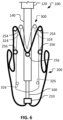
- a sheath 120 (which is a part of the transcatheter delivery system 100) can be used to simultaneously deliver the anchor assembly 200 and the valve assembly 300 to the heart 10. That is, the anchor assembly 200 and the valve assembly 300 can be elastically collapsed to reduced diameters and constrained within the confines of the low-profile sheath 120. In that arrangement, the sheath 120 (containing the anchor assembly 200 and the valve assembly 300 in radially collapsed configurations) can be navigated through the patient's vasculature and heart to arrive at the target location (e.g., within the heart proximate to the patient's native mitral valve). There, the anchor assembly 200 and the valve assembly 300 can be expressed out of the sheath 120.
- FIG. 5 depicts the anchor assembly 200 and the valve assembly 300 after having been expressed from the sheath 120. As shown in this embodiment, the valve assembly 300 is nested within the anchor assembly 200.
- the sheath 120 has an outer diameter of about 28 Fr (about 9.3 mm), or about 30 Fr (about 10.0 mm). In some embodiments, the sheath 120 has an outer diameter in the range of about 26 Fr to about 34 Fr (about 8.7 mm to about 11.3 mm). In some embodiments, the sheath 120 has an outer diameter in the range of about 20 Fr to about 28 Fr (about 6.7 mm to about 9.3 mm).
- the transcatheter delivery system 100 can also include a delivery catheter 140.
- the anchor assembly 200 and the valve assembly 300 can be attached to the delivery catheter 140 using one or more control wires.
- the delivery catheter 140 can thereby control the positioning of the anchor assembly 200 and the valve assembly 300 relative to the sheath 120.
- the delivery catheter 140 can be pushed distally while the sheath 120 is held stationary to make the anchor assembly 200 and the valve assembly 300 emerge from within the sheath 120.
- the sheath 120 can be pulled proximally while the delivery catheter 140 is held stationary to make the anchor assembly 200 and the valve assembly 300 emerge from within the sheath 120.
- the transcatheter delivery system 100 can also include an inner catheter 160 (also referred to herein as a "pusher catheter 160").
- the inner catheter 160 is releasably coupled with the hub 210 of the anchor assembly 200.
- a distal end portion of the inner catheter 160 can be threadedly coupled with the hub 210.
- the inner catheter 160 can be moved (e.g., pushed distally) or held stationary in concert with the delivery catheter 140.
- components of the transcatheter delivery system 100 can include one or more of the following features.
- one or more portions of the components of the transcatheter delivery system 100 are steerable (also referred to herein as "deflectable"). Using such steering, the transcatheter delivery system 100 can be deflected to navigate the patient's anatomy and/or to be positioned in relation to the patient's anatomy as desired.
- the sheath 120 can be angled within the right atrium 12 to navigate the sheath 120 from the inferior vena cava 11 to the atrial septum. Accordingly, in some embodiments the sheath 120 may include at least one deflectable zone.
- one or more components of the transcatheter delivery system 100 can include one or more portions that have differing properties as compared to other portions of the component.
- a component such as the sheath 120, the delivery catheter 140, and/or the inner catheter 160 may have a portion that has greater flexibility, stiffness, column strength, and/or the like as compared to other portions of that same component.
- the sheath 120, the delivery catheter 140, and/or the inner catheter 160 can comprise a tubular polymeric or metallic material.
- the sheath 120, the delivery catheter 140, and/or the inner catheter 160 can be made from polymeric materials such as, but not limited to, polytetrafluoroethylene (PTFE), fluorinated ethylene propylene (FEP), HYTREL ® , nylon, PICOFLEX ® , PEBAX ® , TECOFLEX ® , and the like, and combinations thereof.
- the sheath 120, the delivery catheter 140, and/or the inner catheter 160 can be made from metallic materials such as, but not limited to, nitinol, stainless steel, stainless steel alloys, titanium, titanium alloys, and the like, and combinations thereof.
- the sheath 120, the delivery catheter 140, and/or the inner catheter 160 can be made from combinations of such polymeric and metallic materials (e.g., polymer layers with metal braid, coil reinforcement, stiffening members, and the like, and combinations thereof).
- one or more control wires can be used to releasably couple the anchor assembly 200 and the valve assembly 300 to the delivery catheter 140.
- Such control wires can also be used by a clinician to control the radial expansion of the anchor assembly 200 and the valve assembly 300-in some optional implementations, to control the radial expansion of the anchor assembly 200 independently from the radial expansion of the valve assembly 300 during the deployment procedure. For example, when a control wire is slackened (tension is relaxed) the associated anchor assembly 200 or valve assembly 300 will be allowed to radially self-expand. Conversely, when a control wire is tensioned, the associated anchor assembly 200 or valve assembly 300 will be radially contracted, compressed, or constrained.
- the control wires may also be thought of as "lassos" because, like a lasso, the control wires function to circumferentially, radially, or diametrically control/constrain the anchor assembly 200 and the valve assembly 300.
- Control wires can be releasably coupled around one or more regions of the anchor assembly 200 and the valve assembly 300.
- control wires can be coupled to a proximal end region, one or more mid-body regions, and/or a distal end region of the anchor assembly 200 and/or the valve assembly 300.
- a single control wire can be coupled to both the anchor assembly 200 and the valve assembly 300.
- a single control wire can be coupled to the proximal end regions of both the anchor assembly 200 and the valve assembly 300.
- Tensioning the single control wire that is coupled to the proximal end regions of both the anchor assembly 200 and the valve assembly 300 will cause the proximal end regions of both the anchor assembly 200 and the valve assembly 300 to be concurrently radially contracted and constrained. Releasing tension from the single control wire that is coupled to the proximal end regions of both the anchor assembly 200 and the valve assembly 300 will allow the proximal end regions of both the anchor assembly 200 and the valve assembly 300 to concurrently radially expand.
- a single control wire is coupled to only one of either the anchor assembly 200 or the valve assembly 300.
- a first control wire can be coupled to one region of either the anchor assembly 200 or the valve assembly 300, and a second control wire can be coupled to another region of same anchor assembly 200 or valve assembly 300.
- the anchor assembly 200 is configured to be releasably coupled with a proximal end region control wire at one or more anchor assembly proximal end coupling sites 254.
- the anchor assembly 200 is configured to be releasably coupled with a mid-body region control wire at one or more anchor assembly mid-body coupling sites 256.
- valve assembly 300 is configured to be releasably coupled with a proximal end region control wire at one or more valve assembly proximal end coupling sites 324.
- valve assembly 300 is configured to be releasably coupled with a distal end region control wire at one or more valve assembly distal end coupling sites 326.
- the control wire coupling sites can be various types of structures to which a wire can be releasably coupled.
- the control wire coupling sites can be a loop of suture material, two loops of suture material, or three or more loops of suture material.
- the control wire coupling sites can be a structure defining an eyelet formed by, or attached to, the framework of the anchor assembly 200 and/or the valve assembly 300.
- the control wire coupling sites can be cells or struts of the framework of the anchor assembly 200 and/or the valve assembly 300. Other types of suitable control wire coupling sites can also be used.
- one or more control wires can releasably couple the valve assembly 300 to the delivery catheter 140 (for enhanced clarity, the control wires coupling the anchor assembly 200 to the delivery catheter 140 are not shown).
- the valve assembly 300 is coupled to the delivery catheter 140 by: (i) a valve assembly proximal end control wire 142 and (ii) a valve assembly distal end control wire 144.
- the valve assembly proximal end control wire 142 can be releasably coupled with the valve assembly proximal end coupling sites 324.
- the valve assembly distal end control wire 144 can be releasably coupled with the valve assembly distal end coupling sites 326.
- one or more control wires can releasably couple the anchor assembly 200 to the delivery catheter 140 (for enhanced clarity, the control wires coupling the valve assembly 300 to the delivery catheter 140 are not shown).
- the anchor assembly 200 is coupled to the delivery catheter 140 by: (i) an anchor assembly proximal end control wire 146 and (ii) an anchor assembly mid-body control wire 148.
- the anchor assembly proximal end control wire 146 can be releasably coupled with the anchor assembly proximal end coupling sites 254.
- the anchor assembly mid-body control wire 148 can be releasably coupled with the anchor assembly mid-body coupling sites 256.
- valve assembly proximal end control wire 142 the valve assembly distal end control wire 144, the anchor assembly proximal end control wire 146, and the anchor assembly mid-body control wire 148) are now depicted.
- fewer than four control wires are included.
- the anchor assembly mid-body control wire 148 is not included (but the valve assembly proximal end control wire 142, the valve assembly distal end control wire 144, and the anchor assembly proximal end control wire 146), for a total of three control wires.
- the proximal ends of the anchor assembly 200 and the valve assembly 300 can share a single control wire, and the valve assembly distal end control wire 144 can be also used, for a total of two control wires.
- proximal ends of the anchor assembly 200 and the valve assembly 300 can share a single control wire, and the valve assembly distal end control wire 144 and the anchor assembly mid-body control wire 148 can be also used, for a total of three control wires.
- a deployment control handle/system (such as the deployment frame system 6 of FIG. 1 ) is used to control the movements of the control wires, and by extension, the movements of the corresponding anchor assembly 200 or valve assembly 300 to which the control wires are coupled.
- the tension of the control wires can be increased or decreased to thereby allow radial self-expansion, or to thereby cause radial contraction/constriction, of the corresponding anchor assembly 200 or valve assembly 300.
- control wires extend through lumens defined in the wall of a catheter, such as the delivery catheter 140.
- the control wires can extend from such lumens through luminal orifices at the end of the catheter, or at non-end luminal orifice locations along the catheter.
- the valve assembly distal end control wire 144 extends from luminal orifices at the end of the delivery catheter 140.
- the valve assembly proximal end control wire 142, the anchor assembly proximal end control wire 146, and the anchor assembly mid-body control wire 148 each extend from non-end luminal orifices located along the delivery catheter 140.
- individual control wires form a loop at the end of the catheter (e.g., the delivery catheter 140). That is, the control wire exits from a first luminal orifice of the catheter, then loops through one or more attachment sites of the anchor assembly 200 and/or the valve assembly 300, then reenters a second luminal orifice of the catheter. Portions of the control wire are slidably positioned within lumens within the wall of the catheter. The two terminal ends of the control wire can be positioned at the user control mechanism (e.g., the deployment frame system 6 of FIG. 1 ).
- a clinician can simply pull on one end of the control wire while allowing the second end of the control wire to freely pass into the catheter wall lumen. As the clinician continues to pull, the entire control wire can be removed from engagement with the anchor assembly 200 and/or the valve assembly 300, and even from within the lumens of the catheter (if so desired).
- control wires e.g., the valve assembly proximal end control wire 142, the valve assembly distal end control wire 144, the anchor assembly proximal end control wire 146, and the anchor assembly mid-body control wire 1408
- fewer than four or more than four control wires can be used in conjunction with the depicted nested arrangement of the anchor assembly 200 and valve assembly 300.
- exactly three control wires are included to couple the nested anchor assembly 200 and valve assembly 300 to the delivery catheter 140.
- a first control wire can be releasably coupled with a proximal end region of the valve assembly 300
- a second control wire can be releasably coupled with a distal end region of the valve assembly 300
- a third control wire can be releasably coupled with a proximal end region of the anchor assembly 200.
- the relative positioning of the inner catheter 160 (coupled to the hub 210) compared to the delivery catheter 140 can be adjusted to provide some control of the expansion of the mid-body of the anchor assembly 210. For example, extending the inner catheter 160 further distally in comparison to the delivery catheter 140 can cause a radial contraction of the mid-body region of the anchor assembly 200.
- a first control wire can be releasably coupled with a distal end region of the valve assembly 300
- a second control wire can be releasably coupled with a mid-body region of the anchor assembly 300
- a third control wire can be releasably coupled with the proximal end regions of both of the anchor assembly 200 and the valve assembly 300. That is, a single control wire can be releasably coupled with the proximal end region of the anchor assembly 200 and also with the proximal end region of the valve assembly 300.
- control wires e.g., the valve assembly proximal end control wire 142, the valve assembly distal end control wire 144, the anchor assembly proximal end control wire 146, and the anchor assembly mid-body control wire 148
- exactly two control wires are included to couple the nested anchor assembly 200 and valve assembly 300 to the delivery catheter 140.
- a first control wire can be releasably coupled with a distal end region of the valve assembly 300
- a second control wire can be releasably coupled with the proximal end regions of both of the anchor assembly 200 and the valve assembly 300. That is, a single control wire can be releasably coupled with the proximal end region of the anchor assembly 200 and also with the proximal end region of the valve assembly 300.
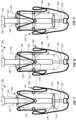
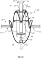
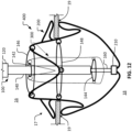
- FIGS. 10-13 schematically depict an example serial process for deploying the anchor assembly 200 in a native heart valve 17 while the anchor assembly 200 and the valve assembly 300 (collectively the two-part prosthetic mitral valve 400; FIGS. 3 and 4 ) are positioned relative to each other in the nested arrangement.
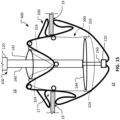
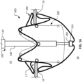
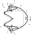
- FIGS. 15-17 schematically depict an example serial process for deploying the valve assembly 300 in the native heart valve 17 while the anchor assembly 200 and the valve assembly 300 are positioned relative to each other in the nested arrangement. It should be understood that retrieval of the anchor assembly 200 and/or the valve assembly 300 can be readily performed at any time during the depicted sequential procedures as long as at least one of the control wires remain coupled to the valve assembly 300.
- the depicted implementation includes four control wires, in some implementations a total of three control wires or a total of two control are included.
- retrieval can be performed, for example, using the following procedure.
- the anchor assembly mid-body control wire 148 can be released and/or removed from engagement with the anchor assembly 200.
- the valve assembly distal end control wire 144 can be tensioned to collapse the distal end of the valve assembly 300.
- the single control wire that is shared by the proximal ends of the anchor assembly 200 and the valve assembly 300 can be tensioned to collapse the proximal end of the valve assembly 300 such that retrieval features (e.g., hooks, clips, slots, etc.) on the delivery catheter 140 become engaged with the framework of the valve assembly 300.
- the single control wire that is shared by the proximal ends of the anchor assembly 200 and the valve assembly 300 can be released/removed to decouple the collapsed valve assembly 300 from the anchor assembly 200 (while the proximal end of the valve assembly 300 remains engaged with the delivery catheter 140 by virtue of the proximally-located retrieval features and valve assembly distal end control wire 144).
- valve assembly 300 can be retracted into sheath 120 (e.g., by pulling the delivery catheter 140 proximally in relation to the sheath 120).
- the retrieval features on the delivery catheter 140 (with which the valve assembly 300 are engaged) and the tensioned valve assembly distal end control wire 144 facilitate the insertion of the valve assembly 300 (along with the delivery catheter 140) into the sheath 120.
- the anchor assembly 200 can be positioned within the sheath 120 by pulling the inner catheter 160 (to which the hub 210 is coupled) into the sheath 120. The anchor assembly 200 may evert as it is pulled into the sheath 120.
- the transcatheter delivery system 100 can be been used to intravascularly navigate the two-part prosthetic mitral valve 400 to the left atrium 16.
- the anchor assembly 200 and the valve assembly 300 (positioned relative to each other in the nested arrangement as shown) can be simultaneously expressed from the sheath 120 while in the left atrium 16.
- Such orienting of the partially or fully expanded nested anchor assembly 200 and valve assembly 300 within the atrium 16 may be advantageous versus having to orient them while they are still constrained within the delivery sheath 120, as the latter assembly can be a relatively large and stiff catheter assembly.
- the nested anchor assembly 200 and valve assembly 300 is expressed from the sheath 120 in the left atrium 16, a clinician can relax some tension from the anchor assembly mid-body control wire 148 to allow the anchor assembly 200 to partially expand.
- the mid-body region of the anchor assembly 200 may be allowed to expand about 75% of its fully expanded radial size.
- the anchor feet 220a, 220b, 220c, and 220d ( FIG. 3 ) expand radially outward. Such expansion can be performed in preparation for seating the anchor feet 220a, 220b, 220c, and 220d within the sub-annular gutter 19 of the native mitral valve 17.
- the other control wires e.g., the valve assembly proximal end control wire 142, the valve assembly distal end control wire 144, and the anchor assembly proximal end control wire 146) can remain fully tensioned such that the proximal end region of the anchor assembly 200 and the entirety of the valve assembly 200 remain radially contracted.
- the nested anchor assembly 200 and valve assembly 300 can be pushed distally as indicated by arrow 50.
- the anchor feet 220a, 220b, 220c, and 220d may physically help to proper align the anchor assembly 200 to the native mitral valve 17 as the anchor assembly 200 is partially pushed through the annulus of the native mitral valve 17.
- the distal portions of the nested anchor assembly 200 and valve assembly 300 will pass through the annulus of the mitral valve 17 and into the left ventricle 18 as shown.
- the anchor assembly 200 With the anchor assembly 200 partially radially contracted in a desired orientation, and appropriately aligned with the mitral valve 17, the anchor assembly 200 can be safely passed through the native mitral valve 17 without damaging the native mitral valve 17 and/or entangling chordae tendineae of the mitral valve 17.
- anchor feet 220a, 220b, 220c, and 220d FIG. 3
- the clinician can fully relax (or nearly fully relax) the tension from the anchor assembly mid-body control wire 148 to allow the mid-body region of the anchor assembly 200 to fully expand (or nearly fully expand).
- the anchor feet 220a, 220b, 220c, and 220d can be then properly seated within the sub-annular gutter 19 of the native mitral valve 17.
- the regions at or near the high collagen annular trigones of the sub-annular gutter 19 can generally be relied upon to provide strong, stable anchoring locations.
- the muscle tissue in the regions at or near the trigones also provides a good tissue ingrowth substrate for added stability and migration resistance of the anchor assembly 200. Therefore, the regions at or near the trigones define a left anterior anchor zone and a right anterior anchor zone.
- the left anterior anchor zone and the right anterior anchor zone provide advantageous target locations for placement of the lateral anterior foot 220a and the medial anterior foot 220d respectively.
- the left posterior anchor zone and the right anterior anchor zone of the sub-annular gutter 19 can receive the lateral posterior foot 220b and the medial posterior foot 220c respectively.
- the clinician can relax the anchor assembly proximal end control wire 146. Doing so will allow the proximal end of the anchor assembly 200, including the supra-annular structures of the anchor assembly 200, to self-expand. For example (referring also to FIG. 3 ), relaxing the tension on the anchor assembly proximal end control wire 146 will allow radial expansion of the atrial holding features 240a, 240b, and 240c.
- the atrial holding features 240a, 240b, and 240c are configured to contact the shelf-like supra-annular tissue surface above the annulus of the mitral valve 17, and to thereby stabilize the anchor assembly 200 in supra-annular areas while providing resistance against migration in the direction towards the left ventricle 18. Relaxing the tension on the anchor assembly proximal end control wire 146 will also allow radial expansion of the lateral anterior anchor arch 250a, the posterior anchor arch 250b, and the medial anterior anchor arch 250c. The lateral anterior anchor arch 250a, the posterior anchor arch 250b, and the medial anterior anchor arch 250c are joined with each other to form the undulating supra-annular ring 250 that acts as a supra-annular structural element for the anchor assembly 200.
- the anchor assembly 200 With the tensions from the anchor assembly proximal end control wire 146 and the anchor assembly mid-body control wire 148 removed, the anchor assembly 200 is fully expanded and engaged with the native mitral valve 17. Thereafter, the clinician can remove the anchor assembly proximal end control wire 146 and the anchor assembly mid-body control wire 148 from engagement with the anchor assembly 200 if so desired. To do so, the clinician can simply pull on a first end of the control wire 146 and/or 148 while the second end of the control wire 146 and/or 148 is free to move.
- the control wire 146 and/or 148 will become disengaged from the anchor assembly 200 as shown.
- the anchor assembly 200 is fully expanded and engaged with the anatomical structure of the native mitral valve 17.
- the inner catheter 160 can continue to be coupled with the hub 210 of the anchor assembly 200. Therefore, retrieval of the anchor assembly 200 is still possible even though the control wires 146 and 148 have been removed from engagement with the anchor assembly 200.
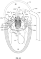
- FIG. 14 illustrates the same arrangement as in FIG. 13 , but in a less schematic fashion.
- the still radially-constrained valve assembly 300 is shown within the expanded anchor assembly 200 that is engaged with the native mitral valve 17.
- This commissural cross-sectional view of the heart 10 is a cross-sectional view taken through the mitral valve 17 along a plane through the left atrium 16 and left ventricle 18 that is parallel to the line that intersects the two commissures of the mitral valve 17. The view is slightly tilted so that better visualization of the two-part prosthetic mitral valve 400 is provided.
- the supra-annular structures of the anchor assembly 200 are radially expanded (e.g., the atrial holding features 240a, 240b, and 240c, and the anchor arches 250a, 250b, and 250c).
- the atrial holding features 240a, 240b, and 240c are in contact with or adjacent to the shelf-like supra-annular tissue surface above the annulus of the mitral valve 17.
- the lateral anterior anchor arch 250a, the posterior anchor arch 250b, and the medial anterior anchor arch 250c are expanded to form the undulating supra-annular ring 250 that acts as a supra-annular structural element for the anchor assembly 200.
- the sub-annular structures of the anchor assembly 200 are also radially expanded (e.g., the anchor feet 220a, 220b, 220c, and 220d). In this arrangement, the anchor feet 220a, 220b, 220c, and 220d are properly seated within the sub-annular gutter 19 of the native mitral valve 17.
- FIG. 15 a schematic depiction of the two-part prosthetic mitral valve 400 arranged in the nested configuration can once again be used to describe the remaining steps of the deployment process.
- the anchor assembly 200 is already deployed at this stage (other than the continued releasable coupling of the inner catheter 160 to the hub 210 of the anchor assembly 200).
- the tensions of the valve assembly proximal end control wire 142 and the valve assembly distal end control wire 144 can be relaxed. Relaxing tension from the valve assembly proximal end control wire 142 and the valve assembly distal end control wire 144 allow the valve assembly 300 to self-expand and to couple with the anchor assembly 200.
- the tensions of the valve assembly proximal end control wire 142 and the valve assembly distal end control wire 144 can be relaxed simultaneously. In some cases, the tensions of the valve assembly proximal end control wire 142 and the valve assembly distal end control wire 144 can be relaxed serially (including any and all possible patterns of altemating, step-wise, and partial relaxations of the tensions).
- valve assembly 300 When the valve assembly 300 and the anchor assembly 200 are coupled together, the valve assembly 300 is geometrically interlocked within the interior space of the anchor assembly 200 (e.g., in some embodiments by virtue of the tapered shape of the valve assembly 300 within the supra-annular ring and interior space of the anchor assembly 200). In particular, in some embodiments the valve assembly 300 is contained within the interior space between the supra-annular ring 250 and the sub-annular support arms 230a, 230b, 230c, and 230d (refer to FIG. 3 ).
- the next step of the process for deploying the two-part prosthetic mitral valve 400 arranged in the nested configuration can include removal of the valve assembly proximal end control wire 142 from engagement with the valve assembly proximal end coupling sites 324, and removal of the valve assembly distal end control wire 144 from engagement with the valve assembly distal end coupling sites 326.
- the removals of the valve assembly proximal end control wire 142 and the valve assembly distal end control wire 144 can be performed as described above in reference to the anchor assembly proximal end control wire 146 and the anchor assembly mid-body control wire 148.
- the clinician can verify that the anchor assembly 200 and the valve assembly 300 are in the desired positions. Additionally, the clinician may verify other aspects such as, but not limited to, the hemodynamic performance and sealing of the anchor assembly 200 and the valve assembly 300.
- the anchor assembly 200 and the valve assembly 300 are deployed at this stage (other than the continued releasable coupling of the inner catheter 160 to the hub 210 of the anchor assembly 200).
- the process of deploying the two-part prosthetic mitral valve 400 arranged in the nested configuration can be completed by disengaging the inner catheter 160 from the hub 210 of the anchor assembly 200, and removing the delivery system 100 from the patient.
- the SAM containment member 212 ( FIG. 3 ) may also be deployed as a result of this step.
- the two-part prosthetic mitral valve 400 engaged with the native mitral valve 17 is thereafter able to take over the performance the native mitral valve function.
Landscapes
- Health & Medical Sciences (AREA)
- Cardiology (AREA)
- Engineering & Computer Science (AREA)
- Biomedical Technology (AREA)
- Heart & Thoracic Surgery (AREA)
- Transplantation (AREA)
- Oral & Maxillofacial Surgery (AREA)
- Vascular Medicine (AREA)
- Life Sciences & Earth Sciences (AREA)
- Animal Behavior & Ethology (AREA)
- General Health & Medical Sciences (AREA)
- Public Health (AREA)
- Veterinary Medicine (AREA)
- Prostheses (AREA)
Claims (10)
- Système transcathéter de remplacement d'une valve mitrale pour un cœur (10), comprenant :une gaine de pose (120) ayant une portion d'extrémité distale pouvant être insérée dans une oreillette gauche ;un cathéter de pose (140) disposé de manière à pouvoir coulisser à l'intérieur de la gaine de pose (120) ; etune valve mitrale prothétique en deux parties (400) accouplée au cathéter de pose (140) par un ou plusieurs fils de contrôle, la valve mitrale prothétique en deux parties (400) configurée pour être mise en place à l'intérieur de la gaine de pose (120) sous un état radialement comprimé et pour s'auto-expanser radialement lorsque la valve mitrale prothétique en deux parties (400) se trouve à l'extérieur de la gaine de pose (120) et n'est pas contrainte par un ou plusieurs fils de contrôle, la valve mitrale prothétique en deux parties (400) comprenant :un ensemble valve (300) incluant un cadre de valve expansible et un dispositif d'occlusion à triple feuillet ;un ensemble ancre (200) pouvant être séparément expansé de l'ensemble valve (300) et définissant un espace intérieur à l'intérieur duquel l'ensemble valve (300) est niché tandis que la valve mitrale prothétique en deux parties (400) se trouve à l'intérieur de la gaine de pose (120) pour le déploiement simultané depuis la gaine de pose (120) ; etun cathéter poussoir (160) disposé de manière à pouvoir coulisser à l'intérieur du cathéter de pose (140) et accouplé de manière à pouvoir être libéré à l'ensemble ancre (200).
- Système selon la revendication 1, dans lequel l'ensemble ancre (200) comprend en outre un raccord (210) et le cathéter poussoir (160) est accouplé de manière à pouvoir être libéré au raccord (210).
- Système selon l'une quelconque des revendications précédentes, dans lequel le un ou plusieurs fils de contrôle comprend :un premier fil de contrôle accouplé à une portion d'extrémité proximale de l'ensemble ancre (200) ;un second fil de contrôle accouplé à une portion de corps médiane de l'ensemble ancre (200) ;un troisième fil de contrôle accouplé à une portion d'extrémité proximale de l'ensemble valve (300) ; etun quatrième fil de contrôle accouplé à une portion d'extrémité distale de l'ensemble valve (300).
- Système selon la revendication 1, dans lequel le un ou plusieurs fils de contrôle comprend :un premier fil de contrôle accouplé à une portion d'extrémité proximale de l'ensemble ancre (200) ;un second fil de contrôle accouplé à une portion d'extrémité proximale de l'ensemble valve (300) ; etun troisième fil de contrôle accouplé à une portion d'extrémité distale de l'ensemble valve (300).
- Système selon la revendication 1, dans lequel le un ou plusieurs fils de contrôle comprend :un premier fil de contrôle accouplé à une portion d'extrémité proximale de l'ensemble ancre (200) et à une portion d'extrémité proximale de l'ensemble valve (300) ;un second fil de contrôle accouplé à une portion de corps médiane de l'ensemble ancre (200) ; etun troisième fil de contrôle accouplé à une portion d'extrémité distale de l'ensemble valve (300).
- Système selon la revendication 1, dans lequel le un ou plusieurs fils de contrôle comprend :un premier fil de contrôle accouplé à une portion d'extrémité proximale de l'ensemble ancre (200) et à une portion d'extrémité proximale de l'ensemble valve (300) ; etun second fil de contrôle accouplé à une portion d'extrémité distale de l'ensemble valve (300).
- Système selon l'une quelconque des revendications précédentes, dans lequel une portion de corps médiane de l'ensemble valve (300) présente une forme transversale en forme de « D ».
- Système selon l'une quelconque des revendications précédentes, dans lequel l'ensemble ancre (200) comprend quatre pieds configurés pour reposer à l'intérieur d'une gouttière sous-annulaire d'une valve mitrale (17) d'origine naturelle lorsque la valve mitrale prothétique en deux parties (400) est implantée à l'intérieur du cœur.
- Système selon la revendication 8, dans lequel l'ensemble ancre (200) comprend des éléments supra-annulaires incluant une bague supra-annulaire ondulante qui définit une extrémité de l'espace intérieur et des éléments de maintien auriculaires configurés pour entrer en contact avec les surfaces tissulaires supra-annulaires au-dessus d'un anneau de la valve mitrale (17).
- Système selon l'une quelconque des revendications précédentes, comprenant en outre un système de commande de déploiement accouplé à des extrémités proximales de la gaine de pose (120) et du cathéter de pose (140), le système de commande de déploiement incluant des mécanismes d'ajustement d'une tension appliquée à un ou plusieurs fils de contrôle.
Priority Applications (1)
| Application Number | Priority Date | Filing Date | Title |
|---|---|---|---|
| EP25150513.7A EP4512373A3 (fr) | 2017-05-26 | 2018-04-19 | Systèmes et procédés de thérapie de valvule cardiaque |
Applications Claiming Priority (2)
| Application Number | Priority Date | Filing Date | Title |
|---|---|---|---|
| US201762511581P | 2017-05-26 | 2017-05-26 | |
| PCT/US2018/028284 WO2018217338A1 (fr) | 2017-05-26 | 2018-04-19 | Systèmes et méthodes pour valvulothérapie cardiaque |
Related Child Applications (2)
| Application Number | Title | Priority Date | Filing Date |
|---|---|---|---|
| EP25150513.7A Division EP4512373A3 (fr) | 2017-05-26 | 2018-04-19 | Systèmes et procédés de thérapie de valvule cardiaque |
| EP25150513.7A Division-Into EP4512373A3 (fr) | 2017-05-26 | 2018-04-19 | Systèmes et procédés de thérapie de valvule cardiaque |
Publications (3)
| Publication Number | Publication Date |
|---|---|
| EP3630004A1 EP3630004A1 (fr) | 2020-04-08 |
| EP3630004A4 EP3630004A4 (fr) | 2021-02-17 |
| EP3630004B1 true EP3630004B1 (fr) | 2025-02-19 |
Family
ID=64396807
Family Applications (2)
| Application Number | Title | Priority Date | Filing Date |
|---|---|---|---|
| EP18805727.7A Active EP3630004B1 (fr) | 2017-05-26 | 2018-04-19 | Systèmes pour valvulothérapie cardiaque |
| EP25150513.7A Pending EP4512373A3 (fr) | 2017-05-26 | 2018-04-19 | Systèmes et procédés de thérapie de valvule cardiaque |
Family Applications After (1)
| Application Number | Title | Priority Date | Filing Date |
|---|---|---|---|
| EP25150513.7A Pending EP4512373A3 (fr) | 2017-05-26 | 2018-04-19 | Systèmes et procédés de thérapie de valvule cardiaque |
Country Status (3)
| Country | Link |
|---|---|
| US (2) | US11213391B2 (fr) |
| EP (2) | EP3630004B1 (fr) |
| WO (1) | WO2018217338A1 (fr) |
Families Citing this family (56)
| Publication number | Priority date | Publication date | Assignee | Title |
|---|---|---|---|---|
| EP3708123A1 (fr) | 2009-03-30 | 2020-09-16 | JC Medical, Inc. | Prothèses valvulaires sans suture, dispositifs et procédés d'administration |
| CN107496054B (zh) | 2011-06-21 | 2020-03-03 | 托尔福公司 | 人工心脏瓣膜装置及相关系统和方法 |
| JP6151705B2 (ja) | 2011-10-19 | 2017-06-21 | トゥエルヴ, インコーポレイテッド | 心臓弁置換のためのデバイス、システムおよび方法 |
| US10016271B2 (en) | 2011-10-19 | 2018-07-10 | Twelve, Inc. | Prosthetic heart valve devices, prosthetic mitral valves and associated systems and methods |
| US9039757B2 (en) | 2011-10-19 | 2015-05-26 | Twelve, Inc. | Prosthetic heart valve devices, prosthetic mitral valves and associated systems and methods |
| US11202704B2 (en) | 2011-10-19 | 2021-12-21 | Twelve, Inc. | Prosthetic heart valve devices, prosthetic mitral valves and associated systems and methods |
| CA2905422A1 (fr) | 2013-03-14 | 2014-10-02 | Cardiovantage Medical, Inc. | Dispositifs de protection contre l'embolie et leurs procedes d'utilisation |
| US11259923B2 (en) | 2013-03-14 | 2022-03-01 | Jc Medical, Inc. | Methods and devices for delivery of a prosthetic valve |
| US11406497B2 (en) | 2013-03-14 | 2022-08-09 | Jc Medical, Inc. | Heart valve prosthesis |
| CN109172046B (zh) | 2015-11-06 | 2022-02-11 | 麦克尔有限公司 | 二尖瓣假体 |
| US10702378B2 (en) | 2017-04-18 | 2020-07-07 | Twelve, Inc. | Prosthetic heart valve device and associated systems and methods |
| EP3630004B1 (fr) | 2017-05-26 | 2025-02-19 | Caisson Interventional, LLC | Systèmes pour valvulothérapie cardiaque |
| US10709591B2 (en) | 2017-06-06 | 2020-07-14 | Twelve, Inc. | Crimping device and method for loading stents and prosthetic heart valves |
| US10786352B2 (en) | 2017-07-06 | 2020-09-29 | Twelve, Inc. | Prosthetic heart valve devices and associated systems and methods |
| US10729541B2 (en) | 2017-07-06 | 2020-08-04 | Twelve, Inc. | Prosthetic heart valve devices and associated systems and methods |
| US10722349B2 (en) * | 2017-12-07 | 2020-07-28 | Medtronic Vascular, Inc. | Adjustable prosthetic heart valve |
| CN210582754U (zh) | 2018-01-07 | 2020-05-22 | 苏州杰成医疗科技有限公司 | 用于输送瓣膜假体的输送系统 |
| CN210697902U (zh) | 2018-01-07 | 2020-06-09 | 苏州杰成医疗科技有限公司 | 心脏瓣膜假体 |
| AU2019220377A1 (en) | 2018-02-15 | 2020-07-16 | Tricares SAS | Stent and replacement heart valve prosthesis with improved fixation features |
| WO2019195860A2 (fr) | 2018-04-04 | 2019-10-10 | Vdyne, Llc | Dispositifs et procédés d'ancrage d'une valvule cardiaque transcathéter |
| US10321995B1 (en) | 2018-09-20 | 2019-06-18 | Vdyne, Llc | Orthogonally delivered transcatheter heart valve replacement |
| US12186187B2 (en) | 2018-09-20 | 2025-01-07 | Vdyne, Inc. | Transcatheter deliverable prosthetic heart valves and methods of delivery |
| US11071627B2 (en) | 2018-10-18 | 2021-07-27 | Vdyne, Inc. | Orthogonally delivered transcatheter heart valve frame for valve in valve prosthesis |
| US11278437B2 (en) | 2018-12-08 | 2022-03-22 | Vdyne, Inc. | Compression capable annular frames for side delivery of transcatheter heart valve replacement |
| US10595994B1 (en) | 2018-09-20 | 2020-03-24 | Vdyne, Llc | Side-delivered transcatheter heart valve replacement |
| US11344413B2 (en) | 2018-09-20 | 2022-05-31 | Vdyne, Inc. | Transcatheter deliverable prosthetic heart valves and methods of delivery |
| US11109969B2 (en) | 2018-10-22 | 2021-09-07 | Vdyne, Inc. | Guidewire delivery of transcatheter heart valve |
| US10653522B1 (en) | 2018-12-20 | 2020-05-19 | Vdyne, Inc. | Proximal tab for side-delivered transcatheter heart valve prosthesis |
| US11253359B2 (en) | 2018-12-20 | 2022-02-22 | Vdyne, Inc. | Proximal tab for side-delivered transcatheter heart valves and methods of delivery |
| WO2020146842A1 (fr) | 2019-01-10 | 2020-07-16 | Vdyne, Llc | Crochet d'ancrage pour prothèse de valvule cardiaque transcathéter à distribution latérale |
| DE102019100530B4 (de) * | 2019-01-10 | 2021-05-06 | Qatna Medical GmbH | Okkluder und System zur Einführung eines Okkluders |
| US11273032B2 (en) | 2019-01-26 | 2022-03-15 | Vdyne, Inc. | Collapsible inner flow control component for side-deliverable transcatheter heart valve prosthesis |
| US11185409B2 (en) | 2019-01-26 | 2021-11-30 | Vdyne, Inc. | Collapsible inner flow control component for side-delivered transcatheter heart valve prosthesis |
| AU2020215234B2 (en) * | 2019-01-28 | 2022-03-17 | Tricares SAS | Three part stent second generation |
| CN113543750B (zh) | 2019-03-05 | 2025-10-10 | 维迪内股份有限公司 | 用于正交经导管心脏瓣膜假体的三尖瓣反流控制装置 |
| US11173027B2 (en) | 2019-03-14 | 2021-11-16 | Vdyne, Inc. | Side-deliverable transcatheter prosthetic valves and methods for delivering and anchoring the same |
| US11076956B2 (en) | 2019-03-14 | 2021-08-03 | Vdyne, Inc. | Proximal, distal, and anterior anchoring tabs for side-delivered transcatheter mitral valve prosthesis |
| US10758346B1 (en) | 2019-03-14 | 2020-09-01 | Vdyne, Inc. | A2 clip for side-delivered transcatheter mitral valve prosthesis |
| US10631983B1 (en) | 2019-03-14 | 2020-04-28 | Vdyne, Inc. | Distal subannular anchoring tab for side-delivered transcatheter valve prosthesis |
| US12186188B2 (en) | 2019-05-01 | 2025-01-07 | Twelve, Inc. | Support devices for transcatheter delivery system handles |
| US11452599B2 (en) | 2019-05-02 | 2022-09-27 | Twelve, Inc. | Fluid diversion devices for hydraulic delivery systems and associated methods |
| AU2020267390B2 (en) | 2019-05-04 | 2025-12-04 | Vdyne, Inc. | Cinch device and method for deployment of a side-delivered prosthetic heart valve in a native annulus |
| US20220226106A1 (en) * | 2019-05-20 | 2022-07-21 | Caisson Interventional Llc | Systems and methods for heart valve therapy |
| JP7584500B2 (ja) | 2019-08-20 | 2024-11-15 | ブイダイン,インコーポレイテッド | 側方送達可能な経カテーテル人工弁の送達及び回収のデバイス及び方法 |
| CN114630665B (zh) | 2019-08-26 | 2025-06-17 | 维迪内股份有限公司 | 可侧面输送的经导管假体瓣膜及其输送和锚定方法 |
| US11234813B2 (en) | 2020-01-17 | 2022-02-01 | Vdyne, Inc. | Ventricular stability elements for side-deliverable prosthetic heart valves and methods of delivery |
| CN115887066B (zh) * | 2021-11-17 | 2024-08-30 | 北京佰仁医疗科技股份有限公司 | 一种分体式可精准锚定的介入主动脉瓣系统 |
| US20250107888A1 (en) * | 2021-11-17 | 2025-04-03 | Beijing Balance Medical Technology Co., Ltd. | Split-type precisely anchorable interventional valve-in-ring system |
| US12268594B2 (en) | 2021-11-17 | 2025-04-08 | Beijing Balance Medical Technology Co., Ltd. | Split-type precisely anchored interventional mitral valve system |
| WO2023088377A1 (fr) * | 2021-11-17 | 2023-05-25 | 北京佰仁医疗科技股份有限公司 | Système de valvule tricuspide d'intervention de type fendu capable d'ancrage avec précision |
| WO2023172485A1 (fr) * | 2022-03-07 | 2023-09-14 | Edwards Lifesciences Corporation | Introducteur avec élément de dilatation et gaines d'accès expansibles |
| CA3258906A1 (fr) * | 2022-05-13 | 2025-03-24 | Cormos Medical Gmbh | Valvule cardiaque artificielle, dispositif pour réaliser une implantation par cathéter d’une valvule cardiaque artificielle, dispositif pour le remplacement in situ d’une valvule cardiaque artificielle interne, procédé d’explantation d’une valvule cardiaque artificielle et procédé de réimplantation d’une valvule cardiaque artificielle |
| CN115670744A (zh) * | 2022-09-08 | 2023-02-03 | 赛诺心畅医疗科技有限公司 | 一种心脏瓣膜原生瓣叶的处理装置及处理方法 |
| EP4601585A1 (fr) | 2022-10-14 | 2025-08-20 | Vdyne, Inc. | Dispositifs et procédés de pose d'une valve cardiaque prothétique à l'aide d'un support supra-annulaire |
| US20240350263A1 (en) * | 2023-04-19 | 2024-10-24 | Laplace Interventional Inc. | Prosthetic heart valves |
| US12440333B1 (en) | 2024-07-17 | 2025-10-14 | Laplace Interventional Inc. | Prosthetic heart valves |
Family Cites Families (10)
| Publication number | Priority date | Publication date | Assignee | Title |
|---|---|---|---|---|
| US9005273B2 (en) | 2003-12-23 | 2015-04-14 | Sadra Medical, Inc. | Assessing the location and performance of replacement heart valves |
| EP3708123A1 (fr) * | 2009-03-30 | 2020-09-16 | JC Medical, Inc. | Prothèses valvulaires sans suture, dispositifs et procédés d'administration |
| ES3023659T3 (en) * | 2010-07-23 | 2025-06-02 | Edwards Lifesciences Corp | Retaining mechanisms for prosthetic valves |
| CN107496054B (zh) * | 2011-06-21 | 2020-03-03 | 托尔福公司 | 人工心脏瓣膜装置及相关系统和方法 |
| US9750607B2 (en) * | 2014-10-23 | 2017-09-05 | Caisson Interventional, LLC | Systems and methods for heart valve therapy |
| CN107405195B (zh) | 2015-01-07 | 2020-09-08 | 坦迪尼控股股份有限公司 | 人造二尖瓣以及用于递送人造二尖瓣的设备和方法 |
| WO2017030940A1 (fr) * | 2015-08-14 | 2017-02-23 | Caisson Interventional Llc | Systèmes et procédés pour thérapie de valvule cardiaque |
| WO2017218375A1 (fr) * | 2016-06-13 | 2017-12-21 | Tendyne Holdings, Inc. | Administration séquentielle de valvule mitrale prothétique en deux parties |
| US10433961B2 (en) * | 2017-04-18 | 2019-10-08 | Twelve, Inc. | Delivery systems with tethers for prosthetic heart valve devices and associated methods |
| EP3630004B1 (fr) | 2017-05-26 | 2025-02-19 | Caisson Interventional, LLC | Systèmes pour valvulothérapie cardiaque |
-
2018
- 2018-04-19 EP EP18805727.7A patent/EP3630004B1/fr active Active
- 2018-04-19 WO PCT/US2018/028284 patent/WO2018217338A1/fr not_active Ceased
- 2018-04-19 US US15/957,154 patent/US11213391B2/en active Active
- 2018-04-19 EP EP25150513.7A patent/EP4512373A3/fr active Pending
-
2021
- 2021-12-08 US US17/643,331 patent/US12544225B2/en active Active
Also Published As
| Publication number | Publication date |
|---|---|
| EP3630004A4 (fr) | 2021-02-17 |
| EP4512373A3 (fr) | 2025-06-25 |
| US20180338832A1 (en) | 2018-11-29 |
| EP4512373A2 (fr) | 2025-02-26 |
| US12544225B2 (en) | 2026-02-10 |
| US11213391B2 (en) | 2022-01-04 |
| US20220096231A1 (en) | 2022-03-31 |
| WO2018217338A1 (fr) | 2018-11-29 |
| EP3630004A1 (fr) | 2020-04-08 |
Similar Documents
| Publication | Publication Date | Title |
|---|---|---|
| US12544225B2 (en) | Systems and methods for heart valve therapy | |
| US20230088407A1 (en) | Systems and methods for heart valve therapy | |
| US12115064B2 (en) | Systems and methods for heart valve therapy | |
| US20250228665A1 (en) | Systems and methods for heart valve therapy | |
| US10939998B2 (en) | Systems and methods for heart valve therapy | |
| US20220226106A1 (en) | Systems and methods for heart valve therapy | |
| US10213301B2 (en) | Systems and methods for heart valve therapy | |
| US20260124034A1 (en) | Systems and methods for heart valve therapy |
Legal Events
| Date | Code | Title | Description |
|---|---|---|---|
| STAA | Information on the status of an ep patent application or granted ep patent |
Free format text: STATUS: THE INTERNATIONAL PUBLICATION HAS BEEN MADE |
|
| PUAI | Public reference made under article 153(3) epc to a published international application that has entered the european phase |
Free format text: ORIGINAL CODE: 0009012 |
|
| STAA | Information on the status of an ep patent application or granted ep patent |
Free format text: STATUS: REQUEST FOR EXAMINATION WAS MADE |
|
| 17P | Request for examination filed |
Effective date: 20191126 |
|
| AK | Designated contracting states |
Kind code of ref document: A1 Designated state(s): AL AT BE BG CH CY CZ DE DK EE ES FI FR GB GR HR HU IE IS IT LI LT LU LV MC MK MT NL NO PL PT RO RS SE SI SK SM TR |
|
| AX | Request for extension of the european patent |
Extension state: BA ME |
|
| DAV | Request for validation of the european patent (deleted) | ||
| DAX | Request for extension of the european patent (deleted) | ||
| REG | Reference to a national code |
Ref country code: DE Ref legal event code: R079 Free format text: PREVIOUS MAIN CLASS: A61F0002000000 Ipc: A61F0002240000 Ref document number: 602018079360 Country of ref document: DE |
|
| A4 | Supplementary search report drawn up and despatched |
Effective date: 20210120 |
|
| RIC1 | Information provided on ipc code assigned before grant |
Ipc: A61F 2/24 20060101AFI20210114BHEP |
|
| STAA | Information on the status of an ep patent application or granted ep patent |
Free format text: STATUS: EXAMINATION IS IN PROGRESS |
|
| 17Q | First examination report despatched |
Effective date: 20230705 |
|
| GRAP | Despatch of communication of intention to grant a patent |
Free format text: ORIGINAL CODE: EPIDOSNIGR1 |
|
| STAA | Information on the status of an ep patent application or granted ep patent |
Free format text: STATUS: GRANT OF PATENT IS INTENDED |
|
| INTG | Intention to grant announced |
Effective date: 20240912 |
|
| GRAS | Grant fee paid |
Free format text: ORIGINAL CODE: EPIDOSNIGR3 |
|
| GRAA | (expected) grant |
Free format text: ORIGINAL CODE: 0009210 |
|
| STAA | Information on the status of an ep patent application or granted ep patent |
Free format text: STATUS: THE PATENT HAS BEEN GRANTED |
|
| P01 | Opt-out of the competence of the unified patent court (upc) registered |
Free format text: CASE NUMBER: APP_66737/2024 Effective date: 20241217 |
|
| AK | Designated contracting states |
Kind code of ref document: B1 Designated state(s): AL AT BE BG CH CY CZ DE DK EE ES FI FR GB GR HR HU IE IS IT LI LT LU LV MC MK MT NL NO PL PT RO RS SE SI SK SM TR |
|
| REG | Reference to a national code |
Ref country code: GB Ref legal event code: FG4D |
|
| REG | Reference to a national code |
Ref country code: CH Ref legal event code: EP |
|
| REG | Reference to a national code |
Ref country code: DE Ref legal event code: R096 Ref document number: 602018079360 Country of ref document: DE |
|
| REG | Reference to a national code |
Ref country code: IE Ref legal event code: FG4D |
|
| REG | Reference to a national code |
Ref country code: NL Ref legal event code: MP Effective date: 20250219 |
|
| PG25 | Lapsed in a contracting state [announced via postgrant information from national office to epo] |
Ref country code: RS Free format text: LAPSE BECAUSE OF FAILURE TO SUBMIT A TRANSLATION OF THE DESCRIPTION OR TO PAY THE FEE WITHIN THE PRESCRIBED TIME-LIMIT Effective date: 20250519 |
|
| PG25 | Lapsed in a contracting state [announced via postgrant information from national office to epo] |
Ref country code: FI Free format text: LAPSE BECAUSE OF FAILURE TO SUBMIT A TRANSLATION OF THE DESCRIPTION OR TO PAY THE FEE WITHIN THE PRESCRIBED TIME-LIMIT Effective date: 20250219 |
|
| PG25 | Lapsed in a contracting state [announced via postgrant information from national office to epo] |
Ref country code: PL Free format text: LAPSE BECAUSE OF FAILURE TO SUBMIT A TRANSLATION OF THE DESCRIPTION OR TO PAY THE FEE WITHIN THE PRESCRIBED TIME-LIMIT Effective date: 20250219 |
|
| PGFP | Annual fee paid to national office [announced via postgrant information from national office to epo] |
Ref country code: DE Payment date: 20250305 Year of fee payment: 8 |
|
| PG25 | Lapsed in a contracting state [announced via postgrant information from national office to epo] |
Ref country code: ES Free format text: LAPSE BECAUSE OF FAILURE TO SUBMIT A TRANSLATION OF THE DESCRIPTION OR TO PAY THE FEE WITHIN THE PRESCRIBED TIME-LIMIT Effective date: 20250219 |
|
| REG | Reference to a national code |
Ref country code: LT Ref legal event code: MG9D |
|
| PG25 | Lapsed in a contracting state [announced via postgrant information from national office to epo] |
Ref country code: IS Free format text: LAPSE BECAUSE OF FAILURE TO SUBMIT A TRANSLATION OF THE DESCRIPTION OR TO PAY THE FEE WITHIN THE PRESCRIBED TIME-LIMIT Effective date: 20250619 Ref country code: NO Free format text: LAPSE BECAUSE OF FAILURE TO SUBMIT A TRANSLATION OF THE DESCRIPTION OR TO PAY THE FEE WITHIN THE PRESCRIBED TIME-LIMIT Effective date: 20250519 |
|
| PG25 | Lapsed in a contracting state [announced via postgrant information from national office to epo] |
Ref country code: NL Free format text: LAPSE BECAUSE OF FAILURE TO SUBMIT A TRANSLATION OF THE DESCRIPTION OR TO PAY THE FEE WITHIN THE PRESCRIBED TIME-LIMIT Effective date: 20250219 |
|
| PG25 | Lapsed in a contracting state [announced via postgrant information from national office to epo] |
Ref country code: HR Free format text: LAPSE BECAUSE OF FAILURE TO SUBMIT A TRANSLATION OF THE DESCRIPTION OR TO PAY THE FEE WITHIN THE PRESCRIBED TIME-LIMIT Effective date: 20250219 |
|
| PG25 | Lapsed in a contracting state [announced via postgrant information from national office to epo] |
Ref country code: PT Free format text: LAPSE BECAUSE OF FAILURE TO SUBMIT A TRANSLATION OF THE DESCRIPTION OR TO PAY THE FEE WITHIN THE PRESCRIBED TIME-LIMIT Effective date: 20250620 Ref country code: LV Free format text: LAPSE BECAUSE OF FAILURE TO SUBMIT A TRANSLATION OF THE DESCRIPTION OR TO PAY THE FEE WITHIN THE PRESCRIBED TIME-LIMIT Effective date: 20250219 |
|
| PG25 | Lapsed in a contracting state [announced via postgrant information from national office to epo] |
Ref country code: GR Free format text: LAPSE BECAUSE OF FAILURE TO SUBMIT A TRANSLATION OF THE DESCRIPTION OR TO PAY THE FEE WITHIN THE PRESCRIBED TIME-LIMIT Effective date: 20250520 Ref country code: BG Free format text: LAPSE BECAUSE OF FAILURE TO SUBMIT A TRANSLATION OF THE DESCRIPTION OR TO PAY THE FEE WITHIN THE PRESCRIBED TIME-LIMIT Effective date: 20250219 |
|
| REG | Reference to a national code |
Ref country code: AT Ref legal event code: MK05 Ref document number: 1767603 Country of ref document: AT Kind code of ref document: T Effective date: 20250219 |
|
| PG25 | Lapsed in a contracting state [announced via postgrant information from national office to epo] |
Ref country code: SE Free format text: LAPSE BECAUSE OF FAILURE TO SUBMIT A TRANSLATION OF THE DESCRIPTION OR TO PAY THE FEE WITHIN THE PRESCRIBED TIME-LIMIT Effective date: 20250219 |
|
| PG25 | Lapsed in a contracting state [announced via postgrant information from national office to epo] |
Ref country code: SM Free format text: LAPSE BECAUSE OF FAILURE TO SUBMIT A TRANSLATION OF THE DESCRIPTION OR TO PAY THE FEE WITHIN THE PRESCRIBED TIME-LIMIT Effective date: 20250219 |
|
| PG25 | Lapsed in a contracting state [announced via postgrant information from national office to epo] |
Ref country code: DK Free format text: LAPSE BECAUSE OF FAILURE TO SUBMIT A TRANSLATION OF THE DESCRIPTION OR TO PAY THE FEE WITHIN THE PRESCRIBED TIME-LIMIT Effective date: 20250219 |
|
| PG25 | Lapsed in a contracting state [announced via postgrant information from national office to epo] |
Ref country code: IT Free format text: LAPSE BECAUSE OF FAILURE TO SUBMIT A TRANSLATION OF THE DESCRIPTION OR TO PAY THE FEE WITHIN THE PRESCRIBED TIME-LIMIT Effective date: 20250219 |
|
| PG25 | Lapsed in a contracting state [announced via postgrant information from national office to epo] |
Ref country code: AT Free format text: LAPSE BECAUSE OF FAILURE TO SUBMIT A TRANSLATION OF THE DESCRIPTION OR TO PAY THE FEE WITHIN THE PRESCRIBED TIME-LIMIT Effective date: 20250219 |
|
| PG25 | Lapsed in a contracting state [announced via postgrant information from national office to epo] |
Ref country code: CZ Free format text: LAPSE BECAUSE OF FAILURE TO SUBMIT A TRANSLATION OF THE DESCRIPTION OR TO PAY THE FEE WITHIN THE PRESCRIBED TIME-LIMIT Effective date: 20250219 Ref country code: EE Free format text: LAPSE BECAUSE OF FAILURE TO SUBMIT A TRANSLATION OF THE DESCRIPTION OR TO PAY THE FEE WITHIN THE PRESCRIBED TIME-LIMIT Effective date: 20250219 |
|
| PG25 | Lapsed in a contracting state [announced via postgrant information from national office to epo] |
Ref country code: RO Free format text: LAPSE BECAUSE OF FAILURE TO SUBMIT A TRANSLATION OF THE DESCRIPTION OR TO PAY THE FEE WITHIN THE PRESCRIBED TIME-LIMIT Effective date: 20250219 |
|
| PG25 | Lapsed in a contracting state [announced via postgrant information from national office to epo] |
Ref country code: SK Free format text: LAPSE BECAUSE OF FAILURE TO SUBMIT A TRANSLATION OF THE DESCRIPTION OR TO PAY THE FEE WITHIN THE PRESCRIBED TIME-LIMIT Effective date: 20250219 |
|
| REG | Reference to a national code |
Ref country code: DE Ref legal event code: R097 Ref document number: 602018079360 Country of ref document: DE |
|
| REG | Reference to a national code |
Ref country code: CH Ref legal event code: H13 Free format text: ST27 STATUS EVENT CODE: U-0-0-H10-H13 (AS PROVIDED BY THE NATIONAL OFFICE) Effective date: 20251125 |
|
| PG25 | Lapsed in a contracting state [announced via postgrant information from national office to epo] |
Ref country code: LU Free format text: LAPSE BECAUSE OF NON-PAYMENT OF DUE FEES Effective date: 20250419 |
|
| PG25 | Lapsed in a contracting state [announced via postgrant information from national office to epo] |
Ref country code: MC Free format text: LAPSE BECAUSE OF FAILURE TO SUBMIT A TRANSLATION OF THE DESCRIPTION OR TO PAY THE FEE WITHIN THE PRESCRIBED TIME-LIMIT Effective date: 20250219 |
|
| PLBE | No opposition filed within time limit |
Free format text: ORIGINAL CODE: 0009261 |
|
| STAA | Information on the status of an ep patent application or granted ep patent |
Free format text: STATUS: NO OPPOSITION FILED WITHIN TIME LIMIT |
|
| REG | Reference to a national code |
Ref country code: BE Ref legal event code: MM Effective date: 20250430 |
|
| PG25 | Lapsed in a contracting state [announced via postgrant information from national office to epo] |
Ref country code: FR Free format text: LAPSE BECAUSE OF NON-PAYMENT OF DUE FEES Effective date: 20250419 |
|
| PG25 | Lapsed in a contracting state [announced via postgrant information from national office to epo] |
Ref country code: BE Free format text: LAPSE BECAUSE OF NON-PAYMENT OF DUE FEES Effective date: 20250430 |
|
| PG25 | Lapsed in a contracting state [announced via postgrant information from national office to epo] |
Ref country code: CH Free format text: LAPSE BECAUSE OF NON-PAYMENT OF DUE FEES Effective date: 20250430 |
|
| 26N | No opposition filed |
Effective date: 20251120 |
|
| GBPC | Gb: european patent ceased through non-payment of renewal fee |
Effective date: 20250519 |
|
| PG25 | Lapsed in a contracting state [announced via postgrant information from national office to epo] |
Ref country code: GB Free format text: LAPSE BECAUSE OF NON-PAYMENT OF DUE FEES Effective date: 20250519 |
|
| PG25 | Lapsed in a contracting state [announced via postgrant information from national office to epo] |
Ref country code: IE Free format text: LAPSE BECAUSE OF NON-PAYMENT OF DUE FEES Effective date: 20250419 |