EP3630459B1 - Verfahren zur funktionsüberprüfung einer schlauchbeutelmaschine - Google Patents
Verfahren zur funktionsüberprüfung einer schlauchbeutelmaschine Download PDFInfo
- Publication number
- EP3630459B1 EP3630459B1 EP18729333.7A EP18729333A EP3630459B1 EP 3630459 B1 EP3630459 B1 EP 3630459B1 EP 18729333 A EP18729333 A EP 18729333A EP 3630459 B1 EP3630459 B1 EP 3630459B1
- Authority
- EP
- European Patent Office
- Prior art keywords
- target
- drive
- transverse sealing
- actual
- control system
- Prior art date
- Legal status (The legal status is an assumption and is not a legal conclusion. Google has not performed a legal analysis and makes no representation as to the accuracy of the status listed.)
- Active
Links
Images


Classifications
-
- B—PERFORMING OPERATIONS; TRANSPORTING
- B29—WORKING OF PLASTICS; WORKING OF SUBSTANCES IN A PLASTIC STATE IN GENERAL
- B29C—SHAPING OR JOINING OF PLASTICS; SHAPING OF MATERIAL IN A PLASTIC STATE, NOT OTHERWISE PROVIDED FOR; AFTER-TREATMENT OF THE SHAPED PRODUCTS, e.g. REPAIRING
- B29C65/00—Joining or sealing of preformed parts, e.g. welding of plastics materials; Apparatus therefor
- B29C65/02—Joining or sealing of preformed parts, e.g. welding of plastics materials; Apparatus therefor by heating, with or without pressure
-
- B—PERFORMING OPERATIONS; TRANSPORTING
- B29—WORKING OF PLASTICS; WORKING OF SUBSTANCES IN A PLASTIC STATE IN GENERAL
- B29C—SHAPING OR JOINING OF PLASTICS; SHAPING OF MATERIAL IN A PLASTIC STATE, NOT OTHERWISE PROVIDED FOR; AFTER-TREATMENT OF THE SHAPED PRODUCTS, e.g. REPAIRING
- B29C66/00—General aspects of processes or apparatus for joining preformed parts
- B29C66/01—General aspects dealing with the joint area or with the area to be joined
- B29C66/05—Particular design of joint configurations
- B29C66/10—Particular design of joint configurations particular design of the joint cross-sections
- B29C66/11—Joint cross-sections comprising a single joint-segment, i.e. one of the parts to be joined comprising a single joint-segment in the joint cross-section
- B29C66/112—Single lapped joints
- B29C66/1122—Single lap to lap joints, i.e. overlap joints
-
- B—PERFORMING OPERATIONS; TRANSPORTING
- B29—WORKING OF PLASTICS; WORKING OF SUBSTANCES IN A PLASTIC STATE IN GENERAL
- B29C—SHAPING OR JOINING OF PLASTICS; SHAPING OF MATERIAL IN A PLASTIC STATE, NOT OTHERWISE PROVIDED FOR; AFTER-TREATMENT OF THE SHAPED PRODUCTS, e.g. REPAIRING
- B29C66/00—General aspects of processes or apparatus for joining preformed parts
- B29C66/40—General aspects of joining substantially flat articles, e.g. plates, sheets or web-like materials; Making flat seams in tubular or hollow articles; Joining single elements to substantially flat surfaces
- B29C66/41—Joining substantially flat articles ; Making flat seams in tubular or hollow articles
- B29C66/43—Joining a relatively small portion of the surface of said articles
- B29C66/431—Joining the articles to themselves
- B29C66/4312—Joining the articles to themselves for making flat seams in tubular or hollow articles, e.g. transversal seams
-
- B—PERFORMING OPERATIONS; TRANSPORTING
- B29—WORKING OF PLASTICS; WORKING OF SUBSTANCES IN A PLASTIC STATE IN GENERAL
- B29C—SHAPING OR JOINING OF PLASTICS; SHAPING OF MATERIAL IN A PLASTIC STATE, NOT OTHERWISE PROVIDED FOR; AFTER-TREATMENT OF THE SHAPED PRODUCTS, e.g. REPAIRING
- B29C66/00—General aspects of processes or apparatus for joining preformed parts
- B29C66/80—General aspects of machine operations or constructions and parts thereof
- B29C66/82—Pressure application arrangements, e.g. transmission or actuating mechanisms for joining tools or clamps
- B29C66/822—Transmission mechanisms
- B29C66/8226—Cam mechanisms; Wedges; Eccentric mechanisms
- B29C66/82265—Eccentric mechanisms
-
- B—PERFORMING OPERATIONS; TRANSPORTING
- B29—WORKING OF PLASTICS; WORKING OF SUBSTANCES IN A PLASTIC STATE IN GENERAL
- B29C—SHAPING OR JOINING OF PLASTICS; SHAPING OF MATERIAL IN A PLASTIC STATE, NOT OTHERWISE PROVIDED FOR; AFTER-TREATMENT OF THE SHAPED PRODUCTS, e.g. REPAIRING
- B29C66/00—General aspects of processes or apparatus for joining preformed parts
- B29C66/80—General aspects of machine operations or constructions and parts thereof
- B29C66/83—General aspects of machine operations or constructions and parts thereof characterised by the movement of the joining or pressing tools
- B29C66/834—General aspects of machine operations or constructions and parts thereof characterised by the movement of the joining or pressing tools moving with the parts to be joined
- B29C66/8351—Jaws mounted on rollers, cylinders, drums, bands, belts or chains; Flying jaws
- B29C66/83541—Jaws mounted on rollers, cylinders, drums, bands, belts or chains; Flying jaws flying jaws, e.g. jaws mounted on crank mechanisms or following a hand over hand movement
- B29C66/83543—Jaws mounted on rollers, cylinders, drums, bands, belts or chains; Flying jaws flying jaws, e.g. jaws mounted on crank mechanisms or following a hand over hand movement cooperating flying jaws
-
- B—PERFORMING OPERATIONS; TRANSPORTING
- B29—WORKING OF PLASTICS; WORKING OF SUBSTANCES IN A PLASTIC STATE IN GENERAL
- B29C—SHAPING OR JOINING OF PLASTICS; SHAPING OF MATERIAL IN A PLASTIC STATE, NOT OTHERWISE PROVIDED FOR; AFTER-TREATMENT OF THE SHAPED PRODUCTS, e.g. REPAIRING
- B29C66/00—General aspects of processes or apparatus for joining preformed parts
- B29C66/80—General aspects of machine operations or constructions and parts thereof
- B29C66/84—Specific machine types or machines suitable for specific applications
- B29C66/849—Packaging machines
-
- B—PERFORMING OPERATIONS; TRANSPORTING
- B29—WORKING OF PLASTICS; WORKING OF SUBSTANCES IN A PLASTIC STATE IN GENERAL
- B29C—SHAPING OR JOINING OF PLASTICS; SHAPING OF MATERIAL IN A PLASTIC STATE, NOT OTHERWISE PROVIDED FOR; AFTER-TREATMENT OF THE SHAPED PRODUCTS, e.g. REPAIRING
- B29C66/00—General aspects of processes or apparatus for joining preformed parts
- B29C66/80—General aspects of machine operations or constructions and parts thereof
- B29C66/87—Auxiliary operations or devices
-
- B—PERFORMING OPERATIONS; TRANSPORTING
- B29—WORKING OF PLASTICS; WORKING OF SUBSTANCES IN A PLASTIC STATE IN GENERAL
- B29C—SHAPING OR JOINING OF PLASTICS; SHAPING OF MATERIAL IN A PLASTIC STATE, NOT OTHERWISE PROVIDED FOR; AFTER-TREATMENT OF THE SHAPED PRODUCTS, e.g. REPAIRING
- B29C66/00—General aspects of processes or apparatus for joining preformed parts
- B29C66/80—General aspects of machine operations or constructions and parts thereof
- B29C66/87—Auxiliary operations or devices
- B29C66/872—Starting or stopping procedures
-
- B—PERFORMING OPERATIONS; TRANSPORTING
- B29—WORKING OF PLASTICS; WORKING OF SUBSTANCES IN A PLASTIC STATE IN GENERAL
- B29C—SHAPING OR JOINING OF PLASTICS; SHAPING OF MATERIAL IN A PLASTIC STATE, NOT OTHERWISE PROVIDED FOR; AFTER-TREATMENT OF THE SHAPED PRODUCTS, e.g. REPAIRING
- B29C66/00—General aspects of processes or apparatus for joining preformed parts
- B29C66/80—General aspects of machine operations or constructions and parts thereof
- B29C66/87—Auxiliary operations or devices
- B29C66/876—Maintenance or cleaning
-
- B—PERFORMING OPERATIONS; TRANSPORTING
- B29—WORKING OF PLASTICS; WORKING OF SUBSTANCES IN A PLASTIC STATE IN GENERAL
- B29C—SHAPING OR JOINING OF PLASTICS; SHAPING OF MATERIAL IN A PLASTIC STATE, NOT OTHERWISE PROVIDED FOR; AFTER-TREATMENT OF THE SHAPED PRODUCTS, e.g. REPAIRING
- B29C66/00—General aspects of processes or apparatus for joining preformed parts
- B29C66/90—Measuring or controlling the joining process
- B29C66/92—Measuring or controlling the joining process by measuring or controlling the pressure, the force, the mechanical power or the displacement of the joining tools
- B29C66/922—Measuring or controlling the joining process by measuring or controlling the pressure, the force, the mechanical power or the displacement of the joining tools by measuring the pressure, the force, the mechanical power or the displacement of the joining tools
- B29C66/9221—Measuring or controlling the joining process by measuring or controlling the pressure, the force, the mechanical power or the displacement of the joining tools by measuring the pressure, the force, the mechanical power or the displacement of the joining tools by measuring the pressure, the force or the mechanical power
- B29C66/92211—Measuring or controlling the joining process by measuring or controlling the pressure, the force, the mechanical power or the displacement of the joining tools by measuring the pressure, the force, the mechanical power or the displacement of the joining tools by measuring the pressure, the force or the mechanical power with special measurement means or methods
-
- B—PERFORMING OPERATIONS; TRANSPORTING
- B29—WORKING OF PLASTICS; WORKING OF SUBSTANCES IN A PLASTIC STATE IN GENERAL
- B29C—SHAPING OR JOINING OF PLASTICS; SHAPING OF MATERIAL IN A PLASTIC STATE, NOT OTHERWISE PROVIDED FOR; AFTER-TREATMENT OF THE SHAPED PRODUCTS, e.g. REPAIRING
- B29C66/00—General aspects of processes or apparatus for joining preformed parts
- B29C66/90—Measuring or controlling the joining process
- B29C66/92—Measuring or controlling the joining process by measuring or controlling the pressure, the force, the mechanical power or the displacement of the joining tools
- B29C66/922—Measuring or controlling the joining process by measuring or controlling the pressure, the force, the mechanical power or the displacement of the joining tools by measuring the pressure, the force, the mechanical power or the displacement of the joining tools
- B29C66/9231—Measuring or controlling the joining process by measuring or controlling the pressure, the force, the mechanical power or the displacement of the joining tools by measuring the pressure, the force, the mechanical power or the displacement of the joining tools by measuring the displacement of the joining tools
- B29C66/92311—Measuring or controlling the joining process by measuring or controlling the pressure, the force, the mechanical power or the displacement of the joining tools by measuring the pressure, the force, the mechanical power or the displacement of the joining tools by measuring the displacement of the joining tools with special measurement means or methods
-
- B—PERFORMING OPERATIONS; TRANSPORTING
- B29—WORKING OF PLASTICS; WORKING OF SUBSTANCES IN A PLASTIC STATE IN GENERAL
- B29C—SHAPING OR JOINING OF PLASTICS; SHAPING OF MATERIAL IN A PLASTIC STATE, NOT OTHERWISE PROVIDED FOR; AFTER-TREATMENT OF THE SHAPED PRODUCTS, e.g. REPAIRING
- B29C66/00—General aspects of processes or apparatus for joining preformed parts
- B29C66/90—Measuring or controlling the joining process
- B29C66/92—Measuring or controlling the joining process by measuring or controlling the pressure, the force, the mechanical power or the displacement of the joining tools
- B29C66/924—Measuring or controlling the joining process by measuring or controlling the pressure, the force, the mechanical power or the displacement of the joining tools by controlling or regulating the pressure, the force, the mechanical power or the displacement of the joining tools
- B29C66/9241—Measuring or controlling the joining process by measuring or controlling the pressure, the force, the mechanical power or the displacement of the joining tools by controlling or regulating the pressure, the force, the mechanical power or the displacement of the joining tools by controlling or regulating the pressure, the force or the mechanical power
-
- B—PERFORMING OPERATIONS; TRANSPORTING
- B29—WORKING OF PLASTICS; WORKING OF SUBSTANCES IN A PLASTIC STATE IN GENERAL
- B29C—SHAPING OR JOINING OF PLASTICS; SHAPING OF MATERIAL IN A PLASTIC STATE, NOT OTHERWISE PROVIDED FOR; AFTER-TREATMENT OF THE SHAPED PRODUCTS, e.g. REPAIRING
- B29C66/00—General aspects of processes or apparatus for joining preformed parts
- B29C66/90—Measuring or controlling the joining process
- B29C66/92—Measuring or controlling the joining process by measuring or controlling the pressure, the force, the mechanical power or the displacement of the joining tools
- B29C66/929—Measuring or controlling the joining process by measuring or controlling the pressure, the force, the mechanical power or the displacement of the joining tools characterized by specific pressure, force, mechanical power or displacement values or ranges
- B29C66/9292—Measuring or controlling the joining process by measuring or controlling the pressure, the force, the mechanical power or the displacement of the joining tools characterized by specific pressure, force, mechanical power or displacement values or ranges in explicit relation to another variable, e.g. pressure diagrams
-
- B—PERFORMING OPERATIONS; TRANSPORTING
- B29—WORKING OF PLASTICS; WORKING OF SUBSTANCES IN A PLASTIC STATE IN GENERAL
- B29C—SHAPING OR JOINING OF PLASTICS; SHAPING OF MATERIAL IN A PLASTIC STATE, NOT OTHERWISE PROVIDED FOR; AFTER-TREATMENT OF THE SHAPED PRODUCTS, e.g. REPAIRING
- B29C66/00—General aspects of processes or apparatus for joining preformed parts
- B29C66/90—Measuring or controlling the joining process
- B29C66/96—Measuring or controlling the joining process characterised by the method for implementing the controlling of the joining process
-
- B—PERFORMING OPERATIONS; TRANSPORTING
- B65—CONVEYING; PACKING; STORING; HANDLING THIN OR FILAMENTARY MATERIAL
- B65B—MACHINES, APPARATUS OR DEVICES FOR, OR METHODS OF, PACKAGING ARTICLES OR MATERIALS; UNPACKING
- B65B51/00—Devices for, or methods of, sealing or securing package folds or closures; Devices for gathering or twisting wrappers, or necks of bags
- B65B51/10—Applying or generating heat or pressure or combinations thereof
- B65B51/26—Devices specially adapted for producing transverse or longitudinal seams in webs or tubes
- B65B51/30—Devices, e.g. jaws, for applying pressure and heat, e.g. for subdividing filled tubes
- B65B51/303—Devices, e.g. jaws, for applying pressure and heat, e.g. for subdividing filled tubes reciprocating along only one axis
-
- B—PERFORMING OPERATIONS; TRANSPORTING
- B65—CONVEYING; PACKING; STORING; HANDLING THIN OR FILAMENTARY MATERIAL
- B65B—MACHINES, APPARATUS OR DEVICES FOR, OR METHODS OF, PACKAGING ARTICLES OR MATERIALS; UNPACKING
- B65B57/00—Automatic control, checking, warning, or safety devices
-
- B—PERFORMING OPERATIONS; TRANSPORTING
- B65—CONVEYING; PACKING; STORING; HANDLING THIN OR FILAMENTARY MATERIAL
- B65B—MACHINES, APPARATUS OR DEVICES FOR, OR METHODS OF, PACKAGING ARTICLES OR MATERIALS; UNPACKING
- B65B65/00—Details peculiar to packaging machines and not otherwise provided for; Arrangements of such details
- B65B65/02—Driving gear
-
- B—PERFORMING OPERATIONS; TRANSPORTING
- B29—WORKING OF PLASTICS; WORKING OF SUBSTANCES IN A PLASTIC STATE IN GENERAL
- B29C—SHAPING OR JOINING OF PLASTICS; SHAPING OF MATERIAL IN A PLASTIC STATE, NOT OTHERWISE PROVIDED FOR; AFTER-TREATMENT OF THE SHAPED PRODUCTS, e.g. REPAIRING
- B29C66/00—General aspects of processes or apparatus for joining preformed parts
- B29C66/80—General aspects of machine operations or constructions and parts thereof
- B29C66/82—Pressure application arrangements, e.g. transmission or actuating mechanisms for joining tools or clamps
- B29C66/824—Actuating mechanisms
- B29C66/8246—Servomechanisms, e.g. servomotors
-
- B—PERFORMING OPERATIONS; TRANSPORTING
- B29—WORKING OF PLASTICS; WORKING OF SUBSTANCES IN A PLASTIC STATE IN GENERAL
- B29C—SHAPING OR JOINING OF PLASTICS; SHAPING OF MATERIAL IN A PLASTIC STATE, NOT OTHERWISE PROVIDED FOR; AFTER-TREATMENT OF THE SHAPED PRODUCTS, e.g. REPAIRING
- B29C66/00—General aspects of processes or apparatus for joining preformed parts
- B29C66/90—Measuring or controlling the joining process
- B29C66/92—Measuring or controlling the joining process by measuring or controlling the pressure, the force, the mechanical power or the displacement of the joining tools
- B29C66/924—Measuring or controlling the joining process by measuring or controlling the pressure, the force, the mechanical power or the displacement of the joining tools by controlling or regulating the pressure, the force, the mechanical power or the displacement of the joining tools
- B29C66/9261—Measuring or controlling the joining process by measuring or controlling the pressure, the force, the mechanical power or the displacement of the joining tools by controlling or regulating the pressure, the force, the mechanical power or the displacement of the joining tools by controlling or regulating the displacement of the joining tools
Definitions
- the invention relates to a method for checking the function of a tubular bag machine according to the preamble of claim 1.
- Flow wrapping machines are generically equipped with a drive control that can control several electronic drive units independently of one another. This makes it possible to drive the various functional elements of the packaging machine, in particular the sealing units, in synchronism with the cycle when performing predefined movement sequences.
- the method according to the invention is directed to the functional check of the transverse sealing unit of a tubular bag machine.
- the transverse sealing unit of the generic tubular bag machine comprises at least one drive motor, for example a servo motor, a gear servo motor or a torque motor, with which two transverse sealing jaws that can be driven relative to one another can be driven.
- the film tubes are welded transversely to the conveying direction by means of the transverse sealing jaws.
- transverse sealing jaws are moved together with the inclusion of the film web of the tubular bag and introduced welded by process heat.
- Such generic devices and methods for controlling the movement of transverse sealing units of a tubular bag machine are for example from the EP 0 368 016 A2 , the JP 2006 193176 A , the DE 10 2007 004140 A1 , DE 10 2013 203295 A1 and the EP 0 865 989 A2 famous.
- the described transverse sealing unit comprises two transverse sealing jaws that can be driven relative to one another for welding a packaging film, the position of the drive motor being able to be determined with a rotation angle detector.
- a drive motor which is equipped with a position sensor system to be provided to drive the transverse sealing jaws.
- a drive controller which is to be characterized quite generally by the fact that it can be used to measure the drive torque applied by the drive motor directly or indirectly.
- the drive controller for example, the power consumption of the drive motor can be measured and the drive torque of the drive motor can be derived from this value using the motor characteristics.
- the position sensor system should be characterized quite generally in that the position of the drive motor can be measured directly or indirectly with it.
- the sealing force acting between the transverse sealing jaws is a highly relevant process parameter for maintaining the desired sealing quality.
- the direct measurement of the sealing force between the two transverse sealing jaws is only possible with complex sensor systems, which is why the drive torque of the drive motor is usually used instead in known tubular bag machines is measured. Since the drive torque is transmitted from the mechanical components of the transverse sealing unit to the transverse sealing jaws, the sealing force acting between the transverse sealing jaws can be derived from the respective drive torque of the drive motor using a transfer function that essentially represents the spring stiffness of the mechanical component of the transverse sealing unit.
- the transfer function to be used to characterize the mechanical properties of the transverse sealing unit, with which the drive torque of the drive motor is transferred into the sealing force of the sealing jaws is determined experimentally. Once this transfer function has been set, the flow wrapping machine is then operated, although disturbances and deviations in the transfer function can no longer be determined.
- the transfer function with which the drive torque is translated into the sealing force may change because, for example, the new sealing tool has a different rigidity than the one previously used. Changes in the transfer function can also occur as a result of different installation conditions or the installation of new installation equipment, such as washers.
- the object of the present invention is therefore to propose a method for checking the function of a tubular bag machine with which changes in the transfer function between the drive motor and the transverse sealing unit can be determined.
- the method according to the invention is based first of all on the fact that the film tube is only removed from the sealing zone between the transverse sealing jaws at the beginning of the functional check.
- the transverse sealing jaws are then moved together under specification of a setpoint torque stored in the drive control.
- the actual position of the drive motor is then measured.
- this actual position of the drive motor is last compared with a target position stored in the drive control, which is assigned to the specified target torque. If the measured actual position deviates from the expected target position when the target torque is reached, it can be concluded from this that the transfer function between the drive motor and the transverse sealing unit has undergone an unexpected change, so that the previously existing transfer function should no longer be used .
- method steps b), c) and d) are repeated one after the other for different target torques and the respectively assigned target positions.
- the way in which the target positions assigned to the target torques are determined is basically arbitrary. This can be achieved in a particularly simple manner by first calibrating the transverse sealing unit together with the entire tubular bag machine and thereby providing for known boundary conditions during the operation of the tubular bag machine. In this calibrated operation, the transfer function between the drive motor and the transverse sealing unit can be known as be accepted. The actual position reached for various target torques is then measured, and this measured actual position is then stored in the drive control as the target position for the later function checks. An assigned setpoint position is then stored in the drive control for each setpoint torque.
- the method according to the invention can also be carried out in that when the transverse sealing jaws move together, a target position is specified instead of a target torque. Then the actual torque of the drive motor applied after the target position has been reached is measured and lastly this measured actual torque is compared with a target torque stored in the drive control, which is assigned to the specified target position.
- the diagnostic quality can also be improved with this variant of the method if several target torques are stored in the drive control for several target positions and method steps b), c) and d) are performed one after the other for the different target positions and the respectively assigned target torque. Torques are repeated.
- the target torques that are assigned to the specified target positions can also be recorded in this variant of the method by recording the actual torques when the calibrated tubular bag machine is in operation without a film tube.
- the process temperature present in each case is also of decisive importance. This is because the mechanical strength of the components between the drive motor and the transverse sealing jaws is either increased or decreased depending on the respective temperature. This changes accordingly also the transfer function between the drive motor and the transverse sealing jaws.
- the method according to the invention with method steps a), b), c) and d) is carried out at a reference temperature stored in the drive control.
- the reference temperature would preferably correspond to the temperature at which the target positions or target torques were determined by measuring actual positions or actual torques of the calibrated transverse sealing unit.
- the measured actual values are each compared with the expected setpoint values for the position or the torque of the drive motor.
- the way in which the actual position of the drive motor is measured is basically arbitrary. According to a preferred embodiment, it is provided that the actual position is measured directly with a rotation angle sensor.
- method steps a), b), c) and d) of the two methods according to the invention should preferably be carried out in order to identify or exclude the transverse sealing unit as a possible source of error.
- the method according to the invention can be used for functional testing both of continuously operating tubular bag machines and of intermittently operating tubular bag machines.
- Fig. 1 the transverse sealing unit of a tubular bag machine with two transverse sealing jaws 13a and 13b movable relative to one another is sketched as an example.
- Fig. 1 You can see in Fig. 1 an endlessly produced film tube 09, in which a packaged item can be filled by means of a filler tube 08.
- the film tube 09 is transported in the conveying direction 21.
- the film tube 09 is sealed transversely.
- the transverse sealing jaws 13a and 13b are used for this. These transverse sealing jaws 13a and 13b can be moved towards one another or away from one another in the transverse direction 22 transversely to the conveying direction 21. In the sealing position, the transverse sealing jaws 13a and 13b are moved towards one another, so that the film tube 09 lying between them can be pressed and welded by heating the transverse sealing jaws 13a and 13b.
- the technique for the transverse sealing of tubular bags is known in principle and requires no further explanation.
- the transverse sealing jaws 13a and 13b are in the in Fig. 1
- the illustrated embodiment is arranged in each case on holding rods 16, which are mounted in a holding rod mounting 17 such that they can be linearly displaced in the transverse direction.
- An opposite movement of the transverse sealing jaws 13a and 13b is realized by means of an eccentric arrangement.
- an eccentric element 14a and 14b is attached to the drive shaft 04 for each holding rod 16 in a rotationally fixed manner.
- a coupling element 15 is rotatably mounted, which is pivotable with the associated support rod 16 is in connection.
- the transmission device with the transverse sealing jaws 13a and 13b is part of the transverse sealing unit 11.
- a drive motor 02 with a stator 03a and a stator 03b is provided for driving the drive shaft 04.
- the drive motor 02 is designed in the manner of a drive motor, in which the actual position, namely the angle of rotation ⁇ , and the actual torque M with a corresponding drive controller, which is shown in Fig. 1 is not shown, can be measured.
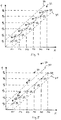
- Fig. 2 shows a diagram for recording target positions, namely target rotation angles ⁇ , each of which is assigned a target torque M.
- target rotation angles ⁇ 1 to ⁇ 6 the entire tubular bag machine with the transverse sealing unit 01 is first calibrated and the film tube 09 between the transverse sealing jaws 13a and 13b is removed. Subsequently, the transverse sealing unit 01 is given the set torques M1, M2, M3, M4, M5 and M6 one after the other by the drive control. As soon as the respective torque values M1 to M6 have been reached, the actual angle of rotation ⁇ determined by the position sensor system is determined and the determined actual angle of rotation is saved as the set angle of rotation ⁇ 1 to ⁇ 6 in the drive control.
- a setpoint rotation angle ⁇ 1 to ⁇ 6 is stored for each setpoint torque M1 to M6, the setpoint torques and setpoint angle of rotation each forming pairs of values.
- the value pairs plotted in the torque-angle of rotation diagram are all on a straight line. The slope of this straight line represents the spring stiffness of the translation between the drive motor 02 and the transverse sealing jaws 13a and 13b.
- Fig. 3 shows the diagram according to Fig. 2 supplemented by two tolerance thresholds 30 and 31.
- the two tolerance thresholds form a corridor around the straight line through the value pairs of the set torques M1 to M6 with the set angles of rotation ⁇ 1 to ⁇ 6.
- FIG. 4 The diagram shown shows the diagram according to Fig. 3 after a first functional check has been carried out. During this functional check, the film tube 02 between the transverse sealing jaws 13a and 13b is again removed and the transverse sealing jaws moved together. Then the target torque M1 to M6 is applied one after the other by the drive motor 02 and the resulting actual angle of rotation of the drive motor 02 is measured in each case.
- the corresponding value pairs 32 are in Fig. 4 marked circled. It can be seen that the six pairs of values 32 that result from the function check all lie on a straight line that is shifted upwards parallel to the straight line through the pairs of values 33 of the target torque and target angle of rotation (see FIG Fig. 3 ).
- This parallel displacement of the spring line can be based, for example, on the fact that when a new transverse sealing tool was installed, a somewhat different distance was implemented between the transverse sealing jaws 13a and 13b. However, since the value pairs 32 are all within the corridor between the tolerance thresholds 30 and 31, an error message does not need to be output.
- Fig. 5 shows the value pairs 34 of a second function check, which represents the actual position, namely the actual angle of rotation together with the respectively applied setpoint torque M1 to M6. It can be seen that the pairs of values 34 also all lie on a straight line, this straight line resulting in a different slope than the straight line through the pairs of values 33 made up of the target torque and target angle of rotation. This other slope of the Spring line through the value pairs 34 can be caused, for example, by the installation of a stiffer component, for example a somewhat stiffer transverse sealing tool. Since the upper three pairs of values 34 lie outside the corridor between the tolerance thresholds 30 and 31, an error message is output in this case so that the operating personnel can carry out an error diagnosis.
Landscapes
- Engineering & Computer Science (AREA)
- Mechanical Engineering (AREA)
- Containers And Plastic Fillers For Packaging (AREA)
- Package Closures (AREA)
Description
- Die Erfindung betrifft Verfahren zur Funktionsüberprüfung einer Schlauchbeutelmaschine nach dem Oberbegriff des Anspruchs 1.
- Schlauchbeutelmaschinen sind gattungsgemäß mit einer Antriebssteuerung ausgestattet, die mehrere elektronische Antriebseinheiten unabhängig voneinander ansteuern kann. Dadurch wird es möglich, die verschiedenen Funktionselemente der Verpackungsmaschine, insbesondere die Siegeleinheiten, beim Abfahren von vordefinierten Bewegungsabläufen taktzeitsynchron anzutreiben. Das erfindungsgemäße Verfahren ist dabei auf die Funktionsüberprüfung der Quersiegeleinheit einer Schlauchbeutelmaschine gerichtet. Die Quersiegeleinheit gattungsgemäßer Schlauchbeutelmaschinen umfasst zumindest einen Antriebsmotor, beispielsweise einen Servomotor, einen Getriebe-Servomotor oder ein Torquemotor, mit dem zwei relativ zueinander antreibbare Quersiegelbacken angetrieben werden können. Mittels der Quersiegelbacken werden die Folienschläuche bei der Herstellung der Schlauchbeutel quer zur Förderrichtung verschweißt. Dazu werden die Quersiegelbacken unter Einschluss der Folienbahn des Schlauchbeutels zusammengefahren und durch Einbringung von Prozesswärme verschweißt. Derartige gattungsgemäße Vorrichtungen und Verfahren zur Steuerung der Bewegung von Quersiegeleinheiten einer Schlauchbeutelmaschine sind beispielsweise aus der
EP 0 368 016 A2 , derJP 2006 193176 A DE 10 2007 004140 A1 ,DE 10 2013 203295 A1 und derEP 0 865 989 A2 bekannt. - Aus der
US 5 653 085 A ist eine Schlauchbeutelmaschine mit einer Antriebssteuerung für mehrere elektronische Antriebseinheiten und einer angetriebenen Quersiegeleinheit bekannt. Die beschriebene Quersiegeleinheit umfasst dabei zum Verschweißen eines Verpackungsfilms zwei zueinander antreibbare Quersiegelbacken, wobei die Stellung des Antriebsmotors mit einem Drehwinkeldetektor ermittelt werden kann. - Gattungsgemäß kann es auch vorgesehen sein, dass zum Antrieb der Quersiegelbacken ein Antriebsmotor vorgesehen ist, der mit einer Lagesensorik ausgestattet ist. Weiter ist ein Antriebsregler vorhanden, der dabei ganz allgemein dadurch charakterisiert werden soll, dass mit ihm mittelbar oder unmittelbar das vom Antriebsmotor aufgebrachte Antriebsmoment gemessen werden kann. Mit dem Antriebsregler kann beispielsweise die Stromaufnahme des Antriebsmotors gemessen und aus diesem Wert das Antriebsmoment des Antriebsmotors unter Verwendung der Motorkennwerte abgeleitet werden.
- Die Stellungssensorik soll ganz allgemein dadurch charakterisiert sein, dass mit ihr mittelbar oder unmittelbar die Stellung des Antriebsmotors gemessen werden kann.
- Für den eigentlichen Siegelprozess in der Schweißzone zwischen den beiden Quersiegelbacken ist die zwischen den Quersiegelbacken wirkende Siegelkraft ein hochrelevanter Prozessparameter für die Einhaltung der gewünschten Siegelqualität. Allerdings ist die unmittelbare Messung der Siegelkraft zwischen den beiden Quersiegelbacken nur mit aufwendigen Sensorsystemen möglich, weshalb stattdessen bei bekannten Schlauchbeutelmaschinen üblicherweise das Antriebsmoment des Antriebsmotors gemessen wird. Da das Antriebsmoment von den mechanischen Komponenten der Quersiegeleinheit auf die Quersiegelbacken übertragen wird, kann die zwischen den Quersiegelbacken wirkende Siegelkraft unter Verwendung einer Übertragungsfunktion, die im Wesentlichen die Federsteifigkeit der mechanischen Komponente der Quersiegeleinheit darstellt, aus dem jeweiligen Antriebsmoment des Antriebsmotors abgeleitet werden. Vielfach wird die jeweils zu verwendende Übertragungsfunktion zur Charakterisierung der mechanischen Eigenschaften der Quersiegeleinheit, mit der das Antriebsmoment des Antriebsmotors in die Siegelkraft der Siegelbacken übertragen wird, experimentell ermittelt. Unter Verwendung dieser einmal eingestellten Übertragungsfunktion wird dann der Betrieb der Schlauchbeutelmaschine vorgenommen, wobei jedoch Störungen und Abweichungen der Übertragungsfunktion nicht mehr feststellbar sind.
- Wird beispielsweise das Siegelwerkzeug in den Quersiegelbacken ausgetauscht, so kann es aufgrund abweichender Montagebedingungen dazu kommen, dass sich die Übertragungsfunktion, mit der das Antriebsmoment in die Siegelkraft übersetzt wird, dadurch verändert, weil beispielsweise das neue Siegelwerkzeug eine andere Steifigkeit aufweist als das zuvor verwendete. Auch durch unterschiedliche Montagebedingungen oder den Einbau neuer Montagemittel, beispielsweise Unterlegscheiben, kann es zu Veränderungen in der Übertragungsfunktion kommen.
- Bei den bekannten Schlauchbeutelmaschinen können diese Änderungen in der Charakteristik der Übertragungsfunktion zwischen Antriebsmotor und Quersiegelbacken nicht festgestellt werden, weshalb bei Störungen des Verpackungsprozesses eine Fehleranalyse vielfach nicht möglich ist.
- Aufgabe der vorliegenden Erfindung ist es deshalb, ein Verfahren zur Funktionsüberprüfung einer Schlauchbeutelmaschine vorzuschlagen, mit der Änderungen der Übertragungsfunktion zwischen Antriebsmotor und Quersiegeleinheit feststellbar sind.
- Diese Aufgabe wird durch die Lehre der beiden unabhängigen Hauptansprüche gelöst.
- Das erfindungsgemäße Verfahren beruht zunächst einmal darauf, dass erst zu Beginn der Funktionsüberprüfung der Folienschlauch aus der Siegelzone zwischen den Quersiegelbacken entfernt wird.
- Gemäß der ersten Variante des erfindungsgemäßen Verfahrens werden die Quersiegelbacken dann unter Vorgabe eines in der Antriebssteuerung abgespeicherten Soll-Drehmoments zusammengefahren. Nach Erreichen des Soll-Drehmoments wird anschließend die Ist-Stellung des Antriebsmotors gemessen. Diese Ist-Stellung des Antriebsmotors wird bei Erreichen des Soll-Drehmoments zuletzt mit einer in der Antriebssteuerung abgespeicherten Soll-Stellung, die dem vorgegebenen Soll-Drehmoment zugeordnet ist, verglichen. Weicht die gemessene Ist-Stellung bei Erreichen des Soll-Drehmoments von der erwarteten Soll-Stellung ab, so kann daraus geschlossen werden, dass die Übertragungsfunktion zwischen Antriebsmotor und Quersiegeleinheit eine unerwartete Änderung erfahren hat, so dass mit der bisher vorhandenen Übertragungsfunktion nicht weiterproduziert werden sollte.
- Um die Diagnose der Änderung der Übertragungsfunktion zwischen Antriebsmotor und Quersiegeleinheit mit größerer Zuverlässigkeit abzusichern, ist es besonders vorteilhaft, wenn die Verfahrensschritte b), c) und d) nacheinander für unterschiedliche Soll-Drehmomente und den jeweils zugeordneten Soll-Stellungen wiederholt werden.
- In welcher Weise die den Soll-Drehmomenten zugeordneten Soll-Stellungen ermittelt werden, ist grundsätzlich beliebig. Besonders einfach kann dies dadurch gelingen, dass zunächst die Quersiegeleinheit zusammen mit der gesamten Schlauchbeutelmaschine kalibriert und dadurch für bekannte Randbedingungen beim Betrieb der Schlauchbeutelmaschine gesorgt werden. In diesem kalibrierten Betrieb kann die Übertragungsfunktion zwischen Antriebsmotor und Quersiegeleinheit als bekannt angenommen werden. Anschließend wird dann die für verschiedene Soll-Drehmomente jeweils erreichte Ist-Stellung gemessen und diese gemessene Ist-Stellung anschließend in der Antriebssteuerung als Soll-Stellung für die späteren Funktionsüberprüfungen abgespeichert. Dabei ist also dann in der Antriebssteuerung für jedes Soll-Drehmoment eine zugeordnete Soll-Stellung abgespeichert.
- Alternativ kann das erfindungsgemäße Verfahren auch dadurch durchgeführt werden, dass beim Zusammenfahren der Quersiegelbacken statt eines Soll-Drehmoments eine Soll-Stellung vorgegeben wird. Anschließend wird dann das nach Erreichen der Soll-Stellung aufgebrachte Ist-Drehmoment des Antriebsmotors gemessen und zuletzt dieses gemessene Ist-Drehmoment mit einem in der Antriebssteuerung abgespeicherten Soll-Drehmoment, das der vorgegebenen Soll-Stellung zugeordnet ist, verglichen.
- Auch bei dieser Verfahrensvariante kann die Diagnosequalität verbessert werden, wenn in der Antriebssteuerung zu mehreren Soll-Stellungen jeweils mehrere Soll-Drehmomente abgespeichert sind und die Verfahrensschritte b), c) und d) nacheinander für die unterschiedlichen Soll-Stellungen und den jeweils zugeordneten Soll-Drehmomenten wiederholt werden.
- Die Soll-Drehmomente, die den vorgegebenen Soll-Stellungen zugeordnet sind, können auch bei dieser Verfahrensvariante durch Aufnahme der Ist-Drehmomente bei Betrieb der kalibrierten Schlauchbeutelmaschine ohne Folienschlauch aufgenommen werden.
- Für das mechanische Verhalten der Übertragung des Antriebsmoments des Antriebsmotors auf die Siegelkraft der Siegeleinheit ist insbesondere auch die jeweils vorhandene Prozesstemperatur von maßgeblicher Bedeutung. Denn die mechanische Festigkeit der Bauteile zwischen Antriebsmotor und Quersiegelbacken wird abhängig von der jeweiligen Temperatur entweder erhöht oder abgesenkt. Entsprechend verändert sich dadurch auch die Übertragungsfunktion zwischen Antriebsmotor und Quersiegelbacken. Um diese Fehlerquelle auszuschalten, ist es deshalb besonders vorteilhaft, wenn das erfindungsgemäße Verfahren mit den Verfahrensschritten a), b), c) und d) bei einer in der Antriebssteuerung abgespeicherten Referenztemperatur durchgeführt wird. Insbesondere ist es vorteilhaft, das erfindungsgemäße Verfahren mit den Verfahrensschritten a), b), c) und d) bei Raumtemperatur durchzuführen.
- Die Referenztemperatur würde dabei bevorzugt der Temperatur entsprechen, bei der die Soll-Stellungen bzw. Soll-Drehmomente durch Messung von Ist-Stellungen bzw. Ist-Drehmomenten der kalibrierten Quersiegeleinheit ermittelt wurden.
- Im Verfahrensschritt d) der beiden erfindungsgemäßen Verfahren werden die gemessenen Ist-Werte jeweils mit den erwarteten Soll-Werten für die Stellung bzw. das Drehmoment des Antriebsmotors verglichen. Um eine Auswertung dieses Vergleichsergebnisses zu erleichtern, ist es besonders vorteilhaft, wenn die im Verfahrensschritt d) ermittelte Differenz zwischen Soll-Stellung und Ist-Stellung bzw. zwischen Soll-Drehmoment und Ist-Drehmoment mit einer in der Antriebssteuerung abgespeicherten Toleranzschwelle verglichen wird. Erst bei Überschreiten der Toleranzschwelle wird dann eine Fehlermeldung ausgegeben. Dadurch wird verhindert, dass bereits sehr kleine Abweichungen zwischen Soll-Wert und Ist-Wert bereits zu einer Fehlermeldung führen.
- In welcher Weise die Ist-Stellung des Antriebsmotors gemessen wird, ist grundsätzlich beliebig. Gemäß einer bevorzugten Ausführungsform ist es vorgesehen, dass die Ist-Stellung unmittelbar mit einem Drehwinkelsensor gemessen wird.
- Weiter ist es auch im Prinzip beliebig, in welcher Weise das Ist-Drehmoment des Antriebsmotors gemessen wird. Besonders einfach kann dies durch mittelbare Messung des Antriebsreglers realisiert werden. Denn Antriebsmotoren gemäß dem Stand der Technik übertragen das vorgesehene Drehmoment mit hoher Genauigkeit .
- Zu welchen Gelegenheiten die erfindungsgemäßen Verfahren zur Funktionsüberprüfung der Quersiegeleinheit einer Schlauchbeutelmaschine eingesetzt werden, ist grundsätzlich beliebig. Besonders vorteilhaft ist es, wenn die Verfahrensschritte a), b), c) und d) nach einem Wechsel der Quersiegelbacken durchgeführt werden. Dadurch kann nach dem Wechsel der Quersiegelbacken sichergestellt werden, dass die in der Schlauchbeutelmaschine voreingestellte Übertragungsfunktion zur Übertragung des Antriebsmoments des Antriebsmotors in die Siegelkraft der Quersiegelbacken auch tatsächlich mit den eingebauten Quersiegelbacken erreicht wird.
- Auch nach Störungen des Betriebs der Schlauchbeutelmaschinen sollten die Verfahrensschritte a), b), c) und d) der beiden erfindungsgemäßen Verfahren bevorzugt durchgeführt werden, um die Quersiegeleinheit als mögliche Fehlerquelle zu identifizieren bzw. auszuschließen.
- Die erfindungsgemäßen Verfahren können zur Funktionsüberprüfung sowohl von kontinuierlich arbeitenden Schlauchbeutelmaschinen als auch von intermittierend arbeitenden Schlauchbeutelmaschinen eingesetzt werden.
- Eine Ausführungsform der Erfindung ist in den Zeichnungen schematisch dargestellt und wird nachfolgend beispielhaft erläutert.
- Es zeigen:
-
Fig. 1 die Quersiegeleinheit einer bekannten Schlauchbeutelmaschine in schematisierter seitlicher Ansicht; -
Fig. 2 ein Diagramm zur Ermittlung der den verschiedenen Soll-Drehmomenten zugeordneten Soll-Stellungen; -
Fig. 3 das Diagramm gemäßFig. 2 nach Einführung von Toleranzschwellen; -
Fig. 4 das Diagramm gemäßFig. 3 nach Ermittlung von Ist-Stellungen während einer ersten Funktionsüberprüfung; -
Fig. 5 das Diagramm gemäßFig. 3 nach Ermittlung von Ist-Stellungen bei einer zweiten Funktionsüberprüfung. - In
Fig. 1 ist die Quersiegeleinheit einer Schlauchbeutelmaschine mit zwei relativ zueinander beweglichen Quersiegelbacken 13a und 13b beispielhaft skizziert. - Zu erkennen ist in
Fig. 1 ein endlos erzeugter Folienschlauch 09, in dem ein Verpackungsgut mittels eines Einfüllrohrs 08 eingefüllt werden kann. Der Folienschlauch 09 wird dabei in Förderrichtung 21 transportiert. Zur Erzeugung der einzelnen Schlauchbeutel wird der Folienschlauch 09 quergesiegelt. Dazu dienen die Quersiegelbacken13a und 13b. Diese Quersiegelbacken 13a und 13b können in Querrichtung 22 quer zur Förderrichtung 21 aufeinander zu- bzw. voneinander wegbewegt werden. In der Siegelstellung werden die Quersiegelbacken 13a und 13b gegeneinander gefahren, so dass der dazwischen liegende Folienschlauch 09 verpresst und durch Beheizen der Quersiegelbacken 13a und 13b verschweißt werden kann. Die Technik für das Quersiegeln von Schlauchbeuteln ist im Prinzip bekannt und bedarf keiner weiteren Erläuterung. - Die Quersiegelbacken 13a und 13b sind in dem in
Fig. 1 dargestellten Ausführungsbeispiel jeweils an Haltestangen 16 angeordnet, die in einer Haltestangenlagerung 17 in Querrichtung linear verschiebbar gelagert sind. Eine gegenläufige Bewegung der Quersiegelbacken 13a und 13b wird mittels einer Exzenteranordnung realisiert. Hierzu wird auf der Antriebswelle 04 je Haltestange 16 ein Exzenterelement 14a und 14b drehfest angeschlagen. Am Exzenterelement 14a bzw. 14b ist wiederum ein Koppelelement 15 drehbar gelagert, welches schwenkbar mit der zugehörigen Haltestange 16 in Verbindung steht. Somit kann die rotierende Drehbewegung 24 der Antriebswelle 04 und zugleich die Exzenterelemente 14a und 14b in alternierender Bewegung der jeweiligen Haltestange 16 und somit der Quersiegelbacken 13a und 13b übertragen werden. - Die Anordnung der Exzenterelemente 14a und 14b auf der Antriebswelle 04 bildet zusammen mit Koppelelement 15 und der Haltestange 16 eine Übersetzungseinrichtung, welche die Drehbewegung 24 der Antriebswelle 04 in alternierende gegenläufige Bewegung der Quersiegelbacken 13a und 13b übersetzt. Die Übersetzungseinrichtung mit den Quersiegelbacken 13a und 13b ist Bestandteil der Quersiegeleinheit 11. Zum Antrieb der Antriebswelle 04 ist ein Antriebsmotor 02 mit einem Ständer 03a und einem Stator 03b vorgesehen. Der Antriebsmotor 02 ist dabei in der Art eines Antriebsmotors ausgebildet, bei dem die Ist-Stellung, nämlich der Drehwinkel ϕ, und das Ist-Drehmoment M mit einem entsprechenden Antriebsregler, der in
Fig. 1 nicht dargestellt ist, gemessen werden kann. -
Fig. 2 zeigt ein Diagramm zur Aufnahme von Soll-Stellungen, nämlich Soll-Drehwinkeln ϕ, die jeweils einen Soll-Drehmoment M zugeordnet werden. Zur Aufnahme der entsprechenden Werte der Soll-Drehwinkel ϕ1 bis ϕ6 wird zunächst die gesamte Schlauchbeutelmaschine mit der Quersiegeleinheit 01 kalibriert und der Folienschlauch 09 zwischen den Quersiegelbacken 13a und 13b entfernt. Anschließend wird der Quersiegeleinheit 01 von der Antriebssteuerung nacheinander die Soll-Drehmomente M1, M2, M3, M4, M5 und M6 vorgegeben. Sobald die jeweiligen Drehmomentwerte M1 bis M6 jeweils erreicht wurden, wird der von der Stellungssensorik ermittelte Ist-Drehwinkel ϕ ermittelt und der ermittelte Ist-Drehwinkel als Soll-Drehwinkel ϕ1 bis ϕ6 in der Antriebssteuerung abgespeichert. Im Ergebnis sind damit nach Ende des Ermittlungsprozesses zu jedem Soll-Drehmoment M1 bis M6 ein Soll-Drehwinkel ϕ1 bis ϕ6 abgespeichert, wobei die Soll-Drehmomente und Soll-Drehwinkel jeweils Wertepaare bilden. Wie inFig. 2 skizzenhaft und beispielhaft dargestellt liegen die im Drehmoment-Drehwinkel-Diagramm angetragenen Wertepaaren jeweils alle auf einer Geraden. Die Steigung dieser Gerade repräsentiert gerade die Federsteifigkeit der Übersetzung zwischen dem Antriebsmotor 02 und den Quersiegelbacken 13a bzw. 13b. -
Fig. 3 zeigt das Diagramm gemäßFig. 2 ergänzt durch zwei Toleranzschwellen 30 und 31. Die beiden Toleranzschwellen bilden dabei einen Korridor um die Gerade durch die Wertepaare der Soll-Drehmomente M1 bis M6 mit den Soll-Drehwinkeln ϕ1 bis ϕ6. - Das in
Fig. 4 dargestellte Diagramm zeigt das Diagramm gemäßFig. 3 nach Durchführung einer ersten Funktionsüberprüfung. Bei dieser Funktionsüberprüfung wird wiederum der Folienschlauch 02 zwischen den Quersiegelbacken 13a und 13b entfernt und die Quersiegelbacken zusammengefahren. Anschließend wird nacheinander das Soll-Drehmoment M1 bis M6 vom Antriebsmotor 02 ausgebracht und jeweils der sich dabei ergebende Ist-Drehwinkel des Antriebsmotors 02 gemessen. Die entsprechenden Wertepaare 32 sind inFig. 4 eingekreist markiert. Man erkennt, dass die sechs Wertepaare 32, die sich bei der Funktionsüberprüfung ergeben, alle auf einer Gerade liegen, die nach oben parallel verschoben ist zur Gerade durch die Wertepaare 33 aus Soll-Drehmoment und Soll-Drehwinkel (sieheFig. 3 ). Diese Parallelverschiebung der Federlinie kann beispielsweise darauf beruhen, dass beim Einbau eines neuen Quersiegelwerkzeugs ein etwas anderer Abstand zwischen den Quersiegelbacken 13a und 13b realisiert wurde. Da die Wertepaare 32 jedoch alle innerhalb des Korridors zwischen den Toleranzschwellen 30 und 31 liegen, braucht eine Fehlermeldung nicht ausgegeben werden. -
Fig. 5 zeigt die Wertepaare 34 einer zweiten Funktionsüberprüfung, die die Ist-Stellung, nämlich den Ist-Drehwinkel zusammen mit dem jeweils aufgebrachten Soll-Drehmoment M1 bis M6 darstellt. Man erkennt, dass auch die Wertepaare 34 alle auf einer Gerade liegen, wobei diese Gerade eine andere Steigung als die Gerade durch die Wertepaare 33 aus Soll-Drehmoment und Soll-Drehwinkel ergibt. Diese andere Steigung der Federlinie durch die Wertepaare 34 kann beispielsweise durch den Einbau eines steiferen Bauteils, beispielsweise eines etwas steiferen Quersiegelwerkzeugs verursacht sein. Da die oberen drei Wertepaare 34 außerhalb des Korridors zwischen den Toleranzschwellen 30 und 31 liegen, wird in diesem Fall eine Fehlermeldung ausgegeben, so dass das Bedienpersonal eine Fehlerdiagnose durchführen kann.
Claims (15)
- Verfahren zur Funktionsüberprüfung einer Schlauchbeutelmaschine, wobei die Schlauchbeutelmaschine eine Antriebsteuerung und mehrere elektronische Antriebseinheiten umfasst, die unabhängig voneinander von der Antriebsteuerung angesteuert werden und die verschiedene Funktionselemente der Verpackungsmaschine beim Abfahren von vordefinierten Bewegungsabläufen taktzeitsynchron antreiben, und wobei eine Antriebseinheit in der Art einer Quersiegeleinheit ausgebildet ist, und wobei die Quersiegeleinheit zumindest einen Antriebsmotors (02) und zwei vom Antriebsmotor (02) relativ zueinander antreibbaren Quersiegelbacken (13a, 13b) umfasst, mittels denen ein Folienschlauch (09) quer zur Förderrichtung (21) verschweißt werden kann, und wobei die Stellung (cp) des Antriebsmotors (02) mit einem Stellungssensor mittelbar oder unmittelbar gemessen werden kann,
dadurch gekennzeichnet,
dass das Antriebsmoment (M) des Antriebsmotors (02) mit einem Antriebsregler mittelbar oder unmittelbar gemessen werden kann, wobei das Verfahren folgende Verfahrensschritteaufweist:a) Entfernen des Folienschlauchs (09) aus der Siegelzone zwischen den Quersiegelbacken (13a, 13b);b) Zusammenfahren der Quersiegelbacken (13a, 13b) unter Vorgabe eines in der Antriebsteuerung gespeicherten Soll-Drehmoments;c) Messen der Ist-Stellung des Antriebsmotors (02) nach Erreichen des Soll-Drehmoments;d) Vergleich der gemessenen Ist-Stellung mit einer in der Antriebsteuerung abgespeicherten Soll-Stellung, die dem vorgegebenen Soll-Drehmoment zugeordnet ist. - Verfahren nach Anspruch 1,
dadurch gekennzeichnet,
dass in der Antriebsteuerung mehrere Soll-Drehmomente mit jeweils einer zugeordneten Soll-Stellung abgespeichert sind, wobei die Verfahrensschritte b), c) und d) nacheinander für die unterschiedlichen Soll-Drehmomente und den jeweils zugeordneten Soll-Stellungen wiederholt werden. - Verfahren nach Anspruch 1 oder 2,
dadurch gekennzeichnet,
dass zur Ermittlung der Soll-Stellungen die Quersiegeleinheit zunächst kalibriert und anschließend für verschiedene Soll-Drehmomente die erreichten Ist-Stellungen gemessen werden, wobei die so gemessenen Ist-Stellungen in der Antriebssteuerung als Soll-Stellungen, die den Soll-Drehmomenten jeweils zugeordnet sind, abgespeichert werden. - Verfahren zur Funktionsüberprüfung einer Schlauchbeutelmaschine, wobei die Schlauchbeutelmaschine eine Antriebsteuerung und mehrere elektronische Antriebseinheiten umfasst, die unabhängig voneinander von der Antriebsteuerung angesteuert werden und die verschiedene Funktionselemente der Verpackungsmaschine beim Abfahren von vordefinierten Bewegungsabläufen taktzeitsynchron antreiben, und wobei eine Antriebseinheit in der Art einer Quersiegeleinheit ausgebildet ist, und wobei die Quersiegeleinheit zumindest einen Antriebsmotors (02) und zwei vom Antriebsmotor (02) relativ zueinander antreibbaren Quersiegelbacken (13a, 13b) umfasst, mittels denen ein Folienschlauch (09) quer zur Förderrichtung (21) verschweißt werden kann, und wobei die Stellung (cp) des Antriebsmotors (02) mit einem Stellungssensor mittelbar oder unmittelbar gemessen werden kann,
dadurch gekennzeichnet,
dass das Antriebsmoment (M) des Antriebsmotors (02) mit einem Antriebsregler mittelbar oder unmittelbar gemessen werden kann, wobei das Verfahren folgende Verfahrensschritte aufweist:a) Entfernen des Folienschlauchs (09) aus der Siegelzone zwischen den Quersiegelbacken (13a, 13b);b) Zusammenfahren der Quersiegelbacken (13a, 13b) unter Vorgabe einer in der Antriebsteuerung gespeicherten Soll-Stellung;c) Messen des Ist-Drehmoments des Antriebsmotors nach Erreichen des Soll-Stellung;d) Vergleich des gemessenen Ist-Drehmoments mit einem in der Antriebsteuerung abgespeicherten Soll-Drehmoment, das der vorgegebenen Soll-Stellung zugeordnet ist. - Verfahren nach Anspruch 4,
dadurch gekennzeichnet,
dass in der Antriebsteuerung mehrere Soll-Stellungen mit jeweils einem zugeordneten Soll-Drehmoment abgespeichert sind, wobei die Verfahrensschritte b), c) und d) nacheinander für die unterschiedlichen Soll-Stellungen und den jeweils zugeordneten Soll-Drehmomenten wiederholt werden. - Verfahren nach Anspruch 4 oder 5,
dadurch gekennzeichnet,
dass zur Ermittlung der Soll-Drehmomente die Quersiegeleinheit zunächst kalibriert und anschließend für verschiedene Soll-Stellungen die erreichten Ist-Drehmomente gemessen werden, wobei die so gemessenen Ist-Drehmomente in der Antriebssteuerung als Soll-Drehmomente, die den Soll-Stellungen jeweils zugeordnet sind, abgespeichert werden. - Verfahren nach einem der Ansprüche 1 bis 6,
dadurch gekennzeichnet,
dass die Verfahrensschritte a), b), c) und d) bei einer in der Antriebssteuerung abgespeicherten Referenztemperatur, insbesondere bei Raumtemperatur, durchgeführt werden. - Verfahren nach Anspruch 7,
dadurch gekennzeichnet,
dass die Referenztemperatur der gemessenen Temperatur entspricht, bei der die Soll-Stellungen oder Soll-Drehmomenten durch Messung von Ist-Stellungen oder Ist-Drehmomenten der kalibrierten Quersiegeleinheit ermittelt wurden. - Verfahren nach einem der Ansprüche 1 bis 8,
dadurch gekennzeichnet,
dass eine im Verfahrensschritt d) ermittelte Differenz zwischen Soll-Stellung und Ist-Stellung oder zwischen Soll-Drehmoment und Ist-Drehmoment mit einem in der Antriebsteuerung abgespeicherten Toleranzschwelle (30, 31) verglichen wird, wobei beim Überschreiten der Toleranzschwelle (30, 31) eine Fehlermeldung ausgegeben wird. - Verfahren nach einem der Ansprüche 1 bis 9,
dadurch gekennzeichnet,
dass die Ist-Stellung unmittelbar mit einem Drehwinkelsensor gemessen wird. - Verfahren nach einem der Ansprüche 1 bis 10,
dadurch gekennzeichnet,
dass das Ist-Drehmoment mittelbar vom Antriebsregler des Antriebsmotors (02) gemessen wird. - Verfahren nach einem der Ansprüche 1 bis 11,
dadurch gekennzeichnet,
dass die Verfahrensschritte a), b), c) und d) nach einem Wechsel der Quersiegelbacken durchgeführt werden. - Verfahren nach einem der Ansprüche 1 bis 11,
dadurch gekennzeichnet,
dass die Verfahrensschritte a), b), c) und d) nach einer Störung des Betriebs der Schlauchbeutelmaschine durchgeführt werden. - Verfahren nach einem der Ansprüche 1 bis 13,
dadurch gekennzeichnet,
dass von den Antriebseinheiten ein Bewegungsablauf zur intermittierenden Herstellung von Schlauchbeuteln abgefahren wird. - Verfahren nach einem der Ansprüche 1 bis 13,
dadurch gekennzeichnet,
dass von den Antriebseinheiten ein Bewegungsablauf zur kontinuierlichen Herstellung von Schlauchbeuteln abgefahren wird.
Applications Claiming Priority (2)
| Application Number | Priority Date | Filing Date | Title |
|---|---|---|---|
| DE102017208766.8A DE102017208766A1 (de) | 2017-05-23 | 2017-05-23 | Verfahren zur Funktionsüberprüfung einer Schlauchbeutelmaschine |
| PCT/EP2018/062682 WO2018215256A1 (de) | 2017-05-23 | 2018-05-16 | Verfahren zur funktionsüberprüfung einer schlauchbeutelmaschine |
Publications (3)
| Publication Number | Publication Date |
|---|---|
| EP3630459A1 EP3630459A1 (de) | 2020-04-08 |
| EP3630459B1 true EP3630459B1 (de) | 2021-08-11 |
| EP3630459B9 EP3630459B9 (de) | 2022-08-17 |
Family
ID=62530178
Family Applications (1)
| Application Number | Title | Priority Date | Filing Date |
|---|---|---|---|
| EP18729333.7A Active EP3630459B9 (de) | 2017-05-23 | 2018-05-16 | Verfahren zur funktionsüberprüfung einer schlauchbeutelmaschine |
Country Status (5)
| Country | Link |
|---|---|
| US (1) | US11370573B2 (de) |
| EP (1) | EP3630459B9 (de) |
| DE (1) | DE102017208766A1 (de) |
| ES (1) | ES2887265T3 (de) |
| WO (1) | WO2018215256A1 (de) |
Families Citing this family (3)
| Publication number | Priority date | Publication date | Assignee | Title |
|---|---|---|---|---|
| EP3950545A4 (de) * | 2019-04-05 | 2022-12-28 | Itoh Denki Co., Ltd. | Fördersystem, vorrichtung zum melden von ursacheninformationen, programm für die vorrichtung zum melden von ursacheninformationen und computerlesbares aufzeichnungsmedium mit darauf aufgezeichnetem programm für die vorrichtung zum melden von ursacheninformationen |
| BE1030346B1 (nl) * | 2022-03-15 | 2023-10-16 | Engilico Eng Solutions Nv | Werkwijze en inrichting voor detecteren van defecten bij het verzegelen van een folie omvattende verpakking |
| CN116572216A (zh) * | 2023-06-05 | 2023-08-11 | 广州达意隆包装机械股份有限公司 | 一种自立袋夹具控制系统、控制方法、装置及存储介质 |
Family Cites Families (10)
| Publication number | Priority date | Publication date | Assignee | Title |
|---|---|---|---|---|
| DE3907208A1 (de) * | 1988-10-18 | 1990-04-19 | Rovema Gmbh | Verfahren und vorrichtung zur steuerung der bewegung von querschweissbacken einer schlauchbeutelmaschine |
| US5322586A (en) * | 1992-05-11 | 1994-06-21 | Reynolds Metals Company | Computer controller heat-sealing machine |
| JP3473861B2 (ja) | 1993-12-28 | 2003-12-08 | 株式会社イシダ | 包材の封止部に介在する介在物の有無の判定方法 |
| WO1996040558A1 (en) * | 1995-06-07 | 1996-12-19 | Tetra Laval Holdings & Finance S.A. | Diagnostic system for a servomotor driven apparatus |
| US5653085A (en) | 1996-05-20 | 1997-08-05 | Ibaraki Seiki Machinery Company, Ltd. | Sealing device for packaging machine |
| US5836136A (en) * | 1997-03-18 | 1998-11-17 | Kliklok Corporation | Seal integrity monitoring and adaptive control method and apparatus |
| JP2006193176A (ja) * | 2005-01-13 | 2006-07-27 | Ishida Co Ltd | 製袋包装機 |
| DE102007004140B4 (de) * | 2007-01-26 | 2018-04-26 | Rovema Gmbh | Schlauchbeutelmaschine |
| US20100108249A1 (en) | 2008-11-05 | 2010-05-06 | Cmd Corporation | Method and Apparatus For Making Sealed Pouches |
| DE102013203295A1 (de) | 2013-02-27 | 2014-08-28 | Rovema Gmbh | Schlauchbeutelmaschine mit kombiniertem Antrieb für zwei Achsen |
-
2017
- 2017-05-23 DE DE102017208766.8A patent/DE102017208766A1/de not_active Ceased
-
2018
- 2018-05-16 US US16/613,358 patent/US11370573B2/en active Active
- 2018-05-16 WO PCT/EP2018/062682 patent/WO2018215256A1/de not_active Ceased
- 2018-05-16 EP EP18729333.7A patent/EP3630459B9/de active Active
- 2018-05-16 ES ES18729333T patent/ES2887265T3/es active Active
Also Published As
| Publication number | Publication date |
|---|---|
| DE102017208766A1 (de) | 2018-11-29 |
| ES2887265T3 (es) | 2021-12-22 |
| US11370573B2 (en) | 2022-06-28 |
| EP3630459B9 (de) | 2022-08-17 |
| EP3630459A1 (de) | 2020-04-08 |
| US20210078745A1 (en) | 2021-03-18 |
| WO2018215256A1 (de) | 2018-11-29 |
Similar Documents
| Publication | Publication Date | Title |
|---|---|---|
| DE102013214019B3 (de) | Spannvorrichtung zum Positionieren von Werkstücken, Werkzeugmaschine mit einer derartigen Spannvorrichtung, Verfahren zum Positionieren von Werkstücken mittels einer derartigen Spannvorrichtung | |
| EP3630459B1 (de) | Verfahren zur funktionsüberprüfung einer schlauchbeutelmaschine | |
| EP2853354B1 (de) | Lageregelung mit Kollisionsvermeidung und Anpassung eines Maschinenmodells an die reale Maschine | |
| DE102020208961B3 (de) | Verfahren zur Ausrichtung eines Roboterarms | |
| DE19723650C2 (de) | Verfahren und Vorrichtung zur Überwachung eines Stellgeräts | |
| DE20321807U1 (de) | Vorrichtung zum Steuern der Andruckkraft einer Schweißzange | |
| DE102014226008B3 (de) | Verfahren zur Überprüfung der Zuordnung eines Antriebs zu einer Steuereinrichtung | |
| DE102019212631A1 (de) | Verfahren zur Zustandsüberwachung einer Vorrichtung und Vorrichtung | |
| EP3630460B1 (de) | Verfahren zur funktionsüberwachung einer schlauchbeutelmaschine | |
| WO2018215258A1 (de) | Verfahren zum betrieb einer schlauchbeutelmaschine und schlauchbeutelmaschine | |
| DE102011001167A1 (de) | Verfahren zum Betreiben einer Schweißvorrichtung, insbesondere eines wärmeimpulsgesteuerten und/oder dauerbeheizten Folienschweiß- und/oder Heißsiegelgerätes mit vorwählbarer elektronischer, prozessorgesteuerter Anpressdruck- und Temperaturregelung und Vorrichtung hierzu | |
| EP1806837B1 (de) | Verfahren zum Testen einer Bremsfunktion eines Roboterantriebes | |
| EP3747734A1 (de) | Ermitteln einer lenkposition bei einem fahrzeuglenksystem mit variabler übersetzung | |
| DE10354526A1 (de) | Industrieroboter mit Reibschweißeinheit und Verfahren zur Steuerung | |
| DE102004047207A1 (de) | Verfahren und Vorrichtung zum Bewegen einer Schweißbacke | |
| AT524080B1 (de) | Vorrichtung und Verfahren zum Erfassen von Geschwindigkeiten von Armsegmenten eines Roboters | |
| DE102005013786A1 (de) | Maschinenfähigkeitsuntersuchung in Winkelschritten | |
| DE102014004877B3 (de) | Antriebssystem und Verfahren zum Betreiben eines Antriebssystems | |
| DE112022005622T5 (de) | Einrichtung zur Herstellung von Behältern, die mit einer Flüssigkeit gefüllt und versiegelt sind | |
| EP3258331B1 (de) | Überwachung einer maschine | |
| DE10204183A1 (de) | Verfahren zum Ermitteln einer fehlerbehafteten Ansteuerung eines über einen Stellantrieb angetriebenen Bauteils | |
| EP2000875B1 (de) | Verfahren zum automatischen Kalibrieren einer Stelleinrichtung für eine regelbare Fluidzuführung | |
| DE10104099A1 (de) | Getriebe und ein Verfahren hierfür | |
| EP3127683B1 (de) | Schweissstation zum verschweissen von folienbeuteln und verfahren dazu | |
| EP4177134B1 (de) | Elektromechanisches lenksystem und verfahren zum betreiben eines elektromechanischen lenksystems mit plausibilitätsprüfung von winkelsensorwerten |
Legal Events
| Date | Code | Title | Description |
|---|---|---|---|
| STAA | Information on the status of an ep patent application or granted ep patent |
Free format text: STATUS: UNKNOWN |
|
| STAA | Information on the status of an ep patent application or granted ep patent |
Free format text: STATUS: THE INTERNATIONAL PUBLICATION HAS BEEN MADE |
|
| PUAI | Public reference made under article 153(3) epc to a published international application that has entered the european phase |
Free format text: ORIGINAL CODE: 0009012 |
|
| STAA | Information on the status of an ep patent application or granted ep patent |
Free format text: STATUS: REQUEST FOR EXAMINATION WAS MADE |
|
| 17P | Request for examination filed |
Effective date: 20191205 |
|
| AK | Designated contracting states |
Kind code of ref document: A1 Designated state(s): AL AT BE BG CH CY CZ DE DK EE ES FI FR GB GR HR HU IE IS IT LI LT LU LV MC MK MT NL NO PL PT RO RS SE SI SK SM TR |
|
| AX | Request for extension of the european patent |
Extension state: BA ME |
|
| DAV | Request for validation of the european patent (deleted) | ||
| DAX | Request for extension of the european patent (deleted) | ||
| GRAP | Despatch of communication of intention to grant a patent |
Free format text: ORIGINAL CODE: EPIDOSNIGR1 |
|
| STAA | Information on the status of an ep patent application or granted ep patent |
Free format text: STATUS: GRANT OF PATENT IS INTENDED |
|
| RIC1 | Information provided on ipc code assigned before grant |
Ipc: B29C 65/02 20060101AFI20210218BHEP Ipc: B65B 51/30 20060101ALI20210218BHEP Ipc: B65B 57/00 20060101ALI20210218BHEP Ipc: B65B 65/02 20060101ALI20210218BHEP |
|
| INTG | Intention to grant announced |
Effective date: 20210305 |
|
| GRAS | Grant fee paid |
Free format text: ORIGINAL CODE: EPIDOSNIGR3 |
|
| GRAA | (expected) grant |
Free format text: ORIGINAL CODE: 0009210 |
|
| STAA | Information on the status of an ep patent application or granted ep patent |
Free format text: STATUS: THE PATENT HAS BEEN GRANTED |
|
| AK | Designated contracting states |
Kind code of ref document: B1 Designated state(s): AL AT BE BG CH CY CZ DE DK EE ES FI FR GB GR HR HU IE IS IT LI LT LU LV MC MK MT NL NO PL PT RO RS SE SI SK SM TR |
|
| REG | Reference to a national code |
Ref country code: CH Ref legal event code: EP |
|
| REG | Reference to a national code |
Ref country code: DE Ref legal event code: R096 Ref document number: 502018006546 Country of ref document: DE |
|
| REG | Reference to a national code |
Ref country code: IE Ref legal event code: FG4D Free format text: LANGUAGE OF EP DOCUMENT: GERMAN Ref country code: AT Ref legal event code: REF Ref document number: 1418947 Country of ref document: AT Kind code of ref document: T Effective date: 20210915 |
|
| REG | Reference to a national code |
Ref country code: NL Ref legal event code: FP |
|
| REG | Reference to a national code |
Ref country code: LT Ref legal event code: MG9D |
|
| REG | Reference to a national code |
Ref country code: ES Ref legal event code: FG2A Ref document number: 2887265 Country of ref document: ES Kind code of ref document: T3 Effective date: 20211222 |
|
| PG25 | Lapsed in a contracting state [announced via postgrant information from national office to epo] |
Ref country code: FI Free format text: LAPSE BECAUSE OF FAILURE TO SUBMIT A TRANSLATION OF THE DESCRIPTION OR TO PAY THE FEE WITHIN THE PRESCRIBED TIME-LIMIT Effective date: 20210811 Ref country code: HR Free format text: LAPSE BECAUSE OF FAILURE TO SUBMIT A TRANSLATION OF THE DESCRIPTION OR TO PAY THE FEE WITHIN THE PRESCRIBED TIME-LIMIT Effective date: 20210811 Ref country code: RS Free format text: LAPSE BECAUSE OF FAILURE TO SUBMIT A TRANSLATION OF THE DESCRIPTION OR TO PAY THE FEE WITHIN THE PRESCRIBED TIME-LIMIT Effective date: 20210811 Ref country code: SE Free format text: LAPSE BECAUSE OF FAILURE TO SUBMIT A TRANSLATION OF THE DESCRIPTION OR TO PAY THE FEE WITHIN THE PRESCRIBED TIME-LIMIT Effective date: 20210811 Ref country code: PT Free format text: LAPSE BECAUSE OF FAILURE TO SUBMIT A TRANSLATION OF THE DESCRIPTION OR TO PAY THE FEE WITHIN THE PRESCRIBED TIME-LIMIT Effective date: 20211213 Ref country code: NO Free format text: LAPSE BECAUSE OF FAILURE TO SUBMIT A TRANSLATION OF THE DESCRIPTION OR TO PAY THE FEE WITHIN THE PRESCRIBED TIME-LIMIT Effective date: 20211111 Ref country code: BG Free format text: LAPSE BECAUSE OF FAILURE TO SUBMIT A TRANSLATION OF THE DESCRIPTION OR TO PAY THE FEE WITHIN THE PRESCRIBED TIME-LIMIT Effective date: 20211111 Ref country code: LT Free format text: LAPSE BECAUSE OF FAILURE TO SUBMIT A TRANSLATION OF THE DESCRIPTION OR TO PAY THE FEE WITHIN THE PRESCRIBED TIME-LIMIT Effective date: 20210811 |
|
| PG25 | Lapsed in a contracting state [announced via postgrant information from national office to epo] |
Ref country code: PL Free format text: LAPSE BECAUSE OF FAILURE TO SUBMIT A TRANSLATION OF THE DESCRIPTION OR TO PAY THE FEE WITHIN THE PRESCRIBED TIME-LIMIT Effective date: 20210811 Ref country code: LV Free format text: LAPSE BECAUSE OF FAILURE TO SUBMIT A TRANSLATION OF THE DESCRIPTION OR TO PAY THE FEE WITHIN THE PRESCRIBED TIME-LIMIT Effective date: 20210811 Ref country code: GR Free format text: LAPSE BECAUSE OF FAILURE TO SUBMIT A TRANSLATION OF THE DESCRIPTION OR TO PAY THE FEE WITHIN THE PRESCRIBED TIME-LIMIT Effective date: 20211112 |
|
| PG25 | Lapsed in a contracting state [announced via postgrant information from national office to epo] |
Ref country code: DK Free format text: LAPSE BECAUSE OF FAILURE TO SUBMIT A TRANSLATION OF THE DESCRIPTION OR TO PAY THE FEE WITHIN THE PRESCRIBED TIME-LIMIT Effective date: 20210811 |
|
| REG | Reference to a national code |
Ref country code: DE Ref legal event code: R097 Ref document number: 502018006546 Country of ref document: DE |
|
| PG25 | Lapsed in a contracting state [announced via postgrant information from national office to epo] |
Ref country code: SM Free format text: LAPSE BECAUSE OF FAILURE TO SUBMIT A TRANSLATION OF THE DESCRIPTION OR TO PAY THE FEE WITHIN THE PRESCRIBED TIME-LIMIT Effective date: 20210811 Ref country code: SK Free format text: LAPSE BECAUSE OF FAILURE TO SUBMIT A TRANSLATION OF THE DESCRIPTION OR TO PAY THE FEE WITHIN THE PRESCRIBED TIME-LIMIT Effective date: 20210811 Ref country code: RO Free format text: LAPSE BECAUSE OF FAILURE TO SUBMIT A TRANSLATION OF THE DESCRIPTION OR TO PAY THE FEE WITHIN THE PRESCRIBED TIME-LIMIT Effective date: 20210811 Ref country code: EE Free format text: LAPSE BECAUSE OF FAILURE TO SUBMIT A TRANSLATION OF THE DESCRIPTION OR TO PAY THE FEE WITHIN THE PRESCRIBED TIME-LIMIT Effective date: 20210811 Ref country code: AL Free format text: LAPSE BECAUSE OF FAILURE TO SUBMIT A TRANSLATION OF THE DESCRIPTION OR TO PAY THE FEE WITHIN THE PRESCRIBED TIME-LIMIT Effective date: 20210811 |
|
| PLBE | No opposition filed within time limit |
Free format text: ORIGINAL CODE: 0009261 |
|
| STAA | Information on the status of an ep patent application or granted ep patent |
Free format text: STATUS: NO OPPOSITION FILED WITHIN TIME LIMIT |
|
| 26N | No opposition filed |
Effective date: 20220512 |
|
| REG | Reference to a national code |
Ref country code: CH Ref legal event code: PK Free format text: BERICHTIGUNG B9 |
|
| PG25 | Lapsed in a contracting state [announced via postgrant information from national office to epo] |
Ref country code: SI Free format text: LAPSE BECAUSE OF FAILURE TO SUBMIT A TRANSLATION OF THE DESCRIPTION OR TO PAY THE FEE WITHIN THE PRESCRIBED TIME-LIMIT Effective date: 20210811 |
|
| REG | Reference to a national code |
Ref country code: CH Ref legal event code: PL |
|
| REG | Reference to a national code |
Ref country code: BE Ref legal event code: MM Effective date: 20220531 |
|
| PG25 | Lapsed in a contracting state [announced via postgrant information from national office to epo] |
Ref country code: MC Free format text: LAPSE BECAUSE OF FAILURE TO SUBMIT A TRANSLATION OF THE DESCRIPTION OR TO PAY THE FEE WITHIN THE PRESCRIBED TIME-LIMIT Effective date: 20210811 Ref country code: LU Free format text: LAPSE BECAUSE OF NON-PAYMENT OF DUE FEES Effective date: 20220516 Ref country code: LI Free format text: LAPSE BECAUSE OF NON-PAYMENT OF DUE FEES Effective date: 20220531 Ref country code: CH Free format text: LAPSE BECAUSE OF NON-PAYMENT OF DUE FEES Effective date: 20220531 |
|
| PG25 | Lapsed in a contracting state [announced via postgrant information from national office to epo] |
Ref country code: IE Free format text: LAPSE BECAUSE OF NON-PAYMENT OF DUE FEES Effective date: 20220516 |
|
| PG25 | Lapsed in a contracting state [announced via postgrant information from national office to epo] |
Ref country code: BE Free format text: LAPSE BECAUSE OF NON-PAYMENT OF DUE FEES Effective date: 20220531 |
|
| P01 | Opt-out of the competence of the unified patent court (upc) registered |
Effective date: 20230524 |
|
| PG25 | Lapsed in a contracting state [announced via postgrant information from national office to epo] |
Ref country code: MK Free format text: LAPSE BECAUSE OF FAILURE TO SUBMIT A TRANSLATION OF THE DESCRIPTION OR TO PAY THE FEE WITHIN THE PRESCRIBED TIME-LIMIT Effective date: 20210811 Ref country code: CY Free format text: LAPSE BECAUSE OF FAILURE TO SUBMIT A TRANSLATION OF THE DESCRIPTION OR TO PAY THE FEE WITHIN THE PRESCRIBED TIME-LIMIT Effective date: 20210811 |
|
| PG25 | Lapsed in a contracting state [announced via postgrant information from national office to epo] |
Ref country code: HU Free format text: LAPSE BECAUSE OF FAILURE TO SUBMIT A TRANSLATION OF THE DESCRIPTION OR TO PAY THE FEE WITHIN THE PRESCRIBED TIME-LIMIT; INVALID AB INITIO Effective date: 20180516 |
|
| REG | Reference to a national code |
Ref country code: AT Ref legal event code: MM01 Ref document number: 1418947 Country of ref document: AT Kind code of ref document: T Effective date: 20230516 |
|
| PG25 | Lapsed in a contracting state [announced via postgrant information from national office to epo] |
Ref country code: AT Free format text: LAPSE BECAUSE OF NON-PAYMENT OF DUE FEES Effective date: 20230516 |
|
| PG25 | Lapsed in a contracting state [announced via postgrant information from national office to epo] |
Ref country code: AT Free format text: LAPSE BECAUSE OF NON-PAYMENT OF DUE FEES Effective date: 20230516 |
|
| PG25 | Lapsed in a contracting state [announced via postgrant information from national office to epo] |
Ref country code: MT Free format text: LAPSE BECAUSE OF FAILURE TO SUBMIT A TRANSLATION OF THE DESCRIPTION OR TO PAY THE FEE WITHIN THE PRESCRIBED TIME-LIMIT Effective date: 20210811 |
|
| PGFP | Annual fee paid to national office [announced via postgrant information from national office to epo] |
Ref country code: NL Payment date: 20250522 Year of fee payment: 8 |
|
| PGFP | Annual fee paid to national office [announced via postgrant information from national office to epo] |
Ref country code: GB Payment date: 20250522 Year of fee payment: 8 Ref country code: ES Payment date: 20250616 Year of fee payment: 8 |
|
| PGFP | Annual fee paid to national office [announced via postgrant information from national office to epo] |
Ref country code: IT Payment date: 20250530 Year of fee payment: 8 |
|
| PGFP | Annual fee paid to national office [announced via postgrant information from national office to epo] |
Ref country code: FR Payment date: 20250523 Year of fee payment: 8 |
|
| PGFP | Annual fee paid to national office [announced via postgrant information from national office to epo] |
Ref country code: CZ Payment date: 20250430 Year of fee payment: 8 |
|
| PGFP | Annual fee paid to national office [announced via postgrant information from national office to epo] |
Ref country code: DE Payment date: 20250722 Year of fee payment: 8 |
|
| PG25 | Lapsed in a contracting state [announced via postgrant information from national office to epo] |
Ref country code: TR Free format text: LAPSE BECAUSE OF FAILURE TO SUBMIT A TRANSLATION OF THE DESCRIPTION OR TO PAY THE FEE WITHIN THE PRESCRIBED TIME-LIMIT Effective date: 20210811 |
|
| PGFP | Annual fee paid to national office [announced via postgrant information from national office to epo] |
Ref country code: AT Payment date: 20260410 Year of fee payment: 5 |