EP3630497B1 - Verbesserte rundeckenschneidemaschine für schulhefte - Google Patents
Verbesserte rundeckenschneidemaschine für schulhefte Download PDFInfo
- Publication number
- EP3630497B1 EP3630497B1 EP18735422.0A EP18735422A EP3630497B1 EP 3630497 B1 EP3630497 B1 EP 3630497B1 EP 18735422 A EP18735422 A EP 18735422A EP 3630497 B1 EP3630497 B1 EP 3630497B1
- Authority
- EP
- European Patent Office
- Prior art keywords
- sucker
- books
- book
- corner cutting
- round corner
- Prior art date
- Legal status (The legal status is an assumption and is not a legal conclusion. Google has not performed a legal analysis and makes no representation as to the accuracy of the status listed.)
- Active
Links
Images


Classifications
-
- B—PERFORMING OPERATIONS; TRANSPORTING
- B42—BOOKBINDING; ALBUMS; FILES; SPECIAL PRINTED MATTER
- B42C—BOOKBINDING
- B42C19/00—Multi-step processes for making books
- B42C19/08—Conveying between operating stations in machines
-
- B—PERFORMING OPERATIONS; TRANSPORTING
- B42—BOOKBINDING; ALBUMS; FILES; SPECIAL PRINTED MATTER
- B42C—BOOKBINDING
- B42C5/00—Preparing the edges or backs of leaves or signatures for binding
- B42C5/02—Preparing the edges or backs of leaves or signatures for binding by rounding or backing
Definitions
- the present invention relates to a round corner cutting machine for exercise note books and more particularly, it relate to an improved round corner cutting machine that is configured to accommodate numbers of sharp cornered books of different size and to round corner cutting of accommodated sharp cornered bound instruction books.
- books are manufactured with sharp corner. Said sharp cornered products may hurt if it is not properly handled by the user. Hence, from the safety point of view, it is required to make it round corner to avoid injury occurred during improper handling.
- the main object of present invention is to provide an improved round corner cutting machine that performs round corner cutting of the books by overcoming the limitations associated with conventional machines.
- Another object of the present invention is to provide an improved corner cutting machine that comprises a simplified mechanism for separating the books from one another from their side edges.
- Further object of the present invention is to provide an improved round corner cutting machine that has simplified mechanism for adjustment to accommodate different size of books.
- One more object of the present invention is to provide an improved round corner cutting machine that is capable of performing round corner cutting of the multiple books simultaneously.
- the present invention relates to an improved round corner cutting machine according to claim 1 and a method according to claim 10.
- the round corner cutting machine according to present invention is described herein by implying that said machine installed in the reel to book binding machine. However, it is within the scope of present invention to utilize said machine independently. It is to be also noted that, in the drawing, identical reference number identify similar element and acts.
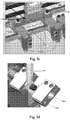
- book binding machine the numbers of sharp cornered books (i.e. 3 ups, 4 ups, 5 ups etc.) are prepared and conveyed towards the round corner cutting operation. Initially, said sharp cornered books are adjacent to each other at their edges. Hence, to accommodate said books, these books are required to be separated from the partition line (B) (shown in Fig. 4a, 4b, 4c ).
- the round corner cutting machine according to present invention is configured to perform separation of books as well as round corner cutting of the separated books.
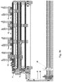
- the round corner cutting machine mainly comprises a books separator sucker assembly (1) to separate out the adjacent sharp cornered books from partition line (B) for easy entry into next unit, a book gripper assembly (2) configured for griping and placing sharp cornered book onto the book separator sucker assembly (1) and conveying the books towards next unit after separation of books, a book stopper assembly (3) ( Fig. 2 ) for adjusting the position of the separated book and a corner cutting assembly (4) for performing corner cutting of separated books.
- Fig. 3 illustrates the diagrams for comprehensive view of the book separator sucker assembly (1).
- said book separator sucker assembly (1) comprises linearly arranged T-shaped linear guide sucker mounting blocks (100, 101, 102, 103), a cam operated lever (104) being connected to a cam shaft (105) through an eccentric bracket (106), extendable connecting links (107, 108), the length of each said link (107, 108) is adjusted by loosing bolts (107a, 108a), one end of each said connecting link (107, 108) is connected to the lever (104) at point (PI, P2) respectively and another end of each link (107, 108) is respectively connected to the guide blocks (100, 101) through bolts (109), said guide blocks (100) and (103) are connected with each other and the guide blocks (101) and (102) are connected with each other through chain sprocket mechanisms (110) and (111) respectively.
- Said eccentric bracket (106) comprises a centre hole (106a) and a side hole (106b).
- Said cam shaft follower (105) is connected with the eccentric block (106) at its end through the side hole (106b) and the lever (104) is connected with the bock (106) at its one end through the center hole (106a).
- Said eccentric bracket (106) is rotated with respect to the side center (106b) along with the rotation of cam shaft (105).
- a distance (A) between the centre hole (106a) and the side hole (106b) is configured in accordance with displacement of the guide blocks (100, 101, 102, 103) during separation of books.
- each said guide bock (100, 101, 102, 103) is configured with two extended adjustment slots (112).
- a sucker cup (113) is fastened on both sides of flat surface of each T shaped guide block through a fastening means (114) so that each guide block is connected with pair of sucker cup (113).
- FIG. 3a and 3b there is shown 4 sets (4 pairs) of sucker cups (113) and each guide block is coupled with pair of sucker cup (113).
- Said fastening means (114) is extended from the sucker cup (113) through the adjustable hole (112) and is secured at its end through a bolt (114a) so that each said guide block (100, 101, 102, 103) is anchored with the pair of sucker cup (113) as shown in Fig. 3c . Further, said suckers cups (113) are slidably supported through bars (115). For smooth sliding of said sucker cups on the bar, bearings or bushes are utilized. Each said sucker cup (113) is equipped with a sucker (116) which is connected to the vacuum pump (not shown) through valve and said valve maintain the on/off of vacuum.
- each guide block (100, 101, 102, 103) is connected with a pair of sucker (116) as shown in Fig. 3a and 3b .
- each pairs of sucker (116) grips a single book by generating vacuum therein through the vacuum pump during separating process.
- one extra middle sucker cup (113) with a sucker (116) is mounted on the bar (115) with respect to centre line (C) such that it divides equal pairs of sucker cup (113) at it's both the side.
- Said middle sucker cup (113) is operated to grip the middle book in position in case of separation of odd numbers (i.e. 3 and 5) of book.
- vacuum connection of the middle sucker (116) is disconnected.
- the distance between two paired sucker cups (113) is adjusted by sliding the sucker cups (113) in the adjustment hole (112) by losing the bolt (114a) such that one book having 2 number of suckers (116) and after adjusting the position of the sucker cups (113), said bolt (114a) is tighten.
- the position of guide blocks (100, 101, 102, 103) are also required to be set.
- the length of said links (107, 108) is adjusted by loosing the bolts (107a, 108a) and also a bolt (109) is loosen for sliding the guide blocks (100, 101, 102, 103) till one book is having pair of sucker (116) and once such position of each guide block is achieved, said bolts are secured.
- the pairs of sucker cups (113) and hence pairs of suckers (116) connected with corresponding guide blocks are also slide along the bars (115) so that the books gripped by said suckers are also separated from their partition line along with separation of pairs of suckers.
- the position of pair of suckers (116) such that each book is gripped by pair of suckers (116).
- the position of suckers (116) and guide blocks (100, 101, 102, 103) can easily be adjusted according to the size of books to be accommodated.
- the numbers of books to be accommodated can also be increased.
- the middle sucker (116) is fixedly supported through the bar (115).
- Said book stopper assembly (3) comprises a back stopper (301), at each back stopper (301) the separated book is stopped, a front jogger cam (302) ( Fig. 1 ) and a side jogger cam (not shown) for adjusting and positioning the books accurately once the book is stopped at the back stopper (301) so that the corner cutting operation is accurately carried out.
- a front jogger cam (302) Fig. 1
- a side jogger cam not shown
- Said corner cutting assembly (4) comprises a top movable knife (401) ( Fig. 2 ) and a bottom stationary knife (not shown) for performing corner cutting operation on the book.
- the product (book) is sensed by sensing means that actuate the corner cutting assembly (4).
- a book holder (402) ( Fig. 2 ) holds the book and the corner cutting of book is carried out by said top and bottom knife.
- the radius of corner cutting portion of the book can be changed by changing the top and bottom knife. According to the numbers of books to be accommodated, such corner cutting assemblies are linearly arranged such that corner cutting of each book is done by the single corner cutting assembly (4).
- the corner cutting machine is configured to accommodate 3, 4, and 5 no. of books.
- the positions of pair of suckers (116) and the guide blocks (100, 101, 102, 103) are pre-adjusted according to the size and numbers of books such that each book is positioned on pair of suckers (116) except that in case of separation of odd numbers of book, the middle book will be placed on the middle sucker.
- first mode as shown in Fig. 4a , four numbers of books are linearly conveyed towards pairs of sucker (116) through their corresponding book griping assemblies (2). Said book gripping assemblies (2) will place the sharp cornered books on the suckers (116) such that each book is placed on the pair of suckers (116).
- vacuum is generated in each sucker (116) by the vacuum pump so that each pair of sucker (116) grip and hold a single book.
- the cam operated lever (104) is operated through the cam shaft (105).
- Said lever (104) will linearly move each guide block (100, 101, 102, 103) by using connecting links (107, 108) and said chain sprocket mechanism (110, 111).
- each pair of sucker cups (113) and hence the pair suckers (116) will also be moved linearly.
- the pairs of suckers (116) are separated from each other whereby the books gripped/sucked by said pairs are also separated from their partition line (B) as shown in Fig. 4a .
- the vacuum connection of the middle sucker (116) is kept in OFF condition.
- the book grippers (2) remain in OFF condition and after separation, said gripping assembly (2) grips the corresponding books again and feed the book towards the back stopper (301).
- Said lever (104) will linearly move said guide blocks (100, 101, 102, 103) with respect to each other by using the connecting links (107, 108) and the chain sprocket mechanism (110, 111).
- each pair of sucker cups (113) and hence the pair of suckers (116) will also travel.
- the pairs of suckers (116) are separated from each other whereby the books gripped/sucked by said pairs are also separated from their partition line (B).
- the middle sucker (116) will remain stationary and only pairs of sucker (116) will be moved so that the books are separated from their partition line (B) as shown in Fig. 4b .
- the vacuum is disconnected and pressurized air will allow book to move inside the back stopper assembly (3).
- each pair of sucker (116) takes it original position for receiving next set of books.
- Said gripping assembly (2) conveys the separated book towards the back stopper assembly (3) where the book is properly positioned by the front jogger cam (302) and the side jogger cam.
- corner cutting of the books is carried by corner cutting assembly (4) so that multiple numbers of books are converted into round cornered mode simultaneously.
- the round corner cutting machine according to the present invention is configured by simplified mechanism to accommodate different size and number of books for performing the corner cutting operation.
Landscapes
- Engineering & Computer Science (AREA)
- Mechanical Engineering (AREA)
- Sheets, Magazines, And Separation Thereof (AREA)
- Making Paper Articles (AREA)
Claims (10)
- Verbesserte Rundeckenschneidemaschine, die dazu ausgebildet ist, scharfeckige, gebundene Anweisungsbücher unterschiedlicher Größe, die linear an einer Teilungslinie (B) aneinander angrenzen, unterzubringen und zu trennen und die Ecken untergebrachter und getrennter scharfeckiger Bücher rundzuschneiden, dadurch gekennzeichnet, dass sie Folgendes umfasst:eine Buch-Trenner-Saugeranordnung (1) zum Unterbringen und Trennen der angrenzenden scharfeckigen Bücher von ihrer Teilungslinie (B), eine Buch-Greifanordnung (2), die dazu ausgebildet ist, das Buch entlang einer seitlichen Kante zu greifen und die Bücher zu der Buch-Trenneranordnung (1) zu befördern, und eine Rücken-Stopperanordnung (3), die Rücken-Stopperanordnung (3) zum Einstellen der Position des getrennten scharfeckigen Buches und eine Eckenschneideanordnung (4) zum Ausführen des Eckenschneidevorgangs an dem von der Buchstopperanordnung (3) positionierten scharfeckigen Buch;wobei die Buch-Trenner-Saugeranordnung (1) linear angeordnete Sauger mit linearen Führungsblöcken (100, 101, 102, 103) umfasst, wobei ein nockenbetätigter Hebel (104) mit einer Nockenwelle (105) verbunden ist durch einen Exzenterbügel (106), Verbindungsglieder (107, 108), Paare von Saugnäpfen (113) zum Greifen der Bücher, ein mittlerer Saugnapf (113), der auf der Mittellinie (C) positioniert ist, derart, dass sie die Paare von Saugnäpfen (113) auf ihren beiden Seiten in die gleiche Anzahl teilt und im Falle von ungerader Anzahl von zu trennenden Büchern das mittlere Buch hält;ein Ende eines jeden Verbindungsglieds (107, 108) ist mit dem Hebel (104) verbunden und ein anderes Ende eines jeden Glieds (107, 108) ist jeweils mit den Führungsblöcken (100, 101) durch Bolzen (109) verbunden;wobei jeder Führungsblock (100, 101, 102, 103) mit zwei erweiterten Einstellschlitzen (112) ausgebildet ist, wobei jeder Führungsblock (100, 101, 102, 103) durch Sichern des Saugnapfes (113) durch den Einstellschlitz (112) mittels Befestigungsmitteln (114) mit dem Paar von Saugnäpfen (113) verbunden ist;wobei jeder Saugnapf (113) mit einem Sauger (116) zum Greifen der Bücher ausgestattet ist;wobei der Abstand zwischen den Saugern (116) eines jeden Paares durch Lockern der Sicherungsmittel (114) und Gleiten der Saugnäpfe (113) innerhalb der Einstellschlitze (112) eingestellt wird;wobei jedes Paar von Saugern (116) mindestens ein Buch greift;wobei die Führungsblöcke (100) und (103) gleichmäßig beabstandet in entgegengesetzte Richtung in Bezug auf die Mittellinie (C) bewegt werden;wobei die Führungsblöcke (101) und (102) gleichmäßig beabstandet in entgegengesetzte Richtung in Bezug auf die Mittellinie (C) bewegt werden;wobei jedes Paar von Saugern (116) sich zusammen mit der Bewegung entsprechender Führungsblöcke (100, 101, 102, 103) durch den nockenbetätigten Hebel (104) bewegt, derart, dass die Bücher von ihrer Teilungslinie (B) zusammen mit der Trennung der Paare von Saugern (116) getrennt werden.
- Verbesserte Rundeckenschneidemaschine nach Anspruch 1, wobei die Paare von Saugnäpfen (113) durch Stangen (115) gleitbar getragen werden.
- Verbesserte Rundeckenschneidemaschine nach Anspruch 1, wobei die Verbindungsglieder (107, 108) erweiterbar sind, wobei die Position der Führungsblöcke (100, 101, 102, 103) durch Einstellen der Länge der Glieder (107, 108) durch Lockern von Bolzen (107a, 108a) und Bolzen (109) eingestellt wird.
- Verbesserte Rundeckenschneidemaschine nach Anspruch 1, wobei jeder Sauger (116) mit einem erzeugten Unterdruckmittel verbunden ist.
- Verbesserte Rundeckenschneidemaschine nach Anspruch 1, wobei der mittlere Saugnapf (113) fest auf der Stange (115) gesichert ist.
- Verbesserte Rundeckenschneidemaschine nach Anspruch 1, wobei die Buchstopperanordnung (3) Mittel zum Einstellen der Position des Buches umfasst.
- Verbesserte Rundeckenschneidemaschine nach Anspruch 1, wobei die Führungsblöcke (100) und (103) miteinander verbunden sind und die Führungsblöcke (101) und (102) jeweils durch den Kettentriebmechanismus (110) und (111) miteinander verbunden sind.
- Verbesserte Rundeckenschneidemaschine nach Anspruch 1, wobei alle Führungsblöcke (100, 101, 102, 103) durch den Kettentriebmechanismus miteinander verbunden sind.
- Verfahren zum Rundeckenschneiden von scharfeckigen gebundenen Anleitungsbüchern durch eine verbesserte Rundeckenschneidemaschine, umfassend die folgenden Schritte:a) Einstellen der Position des Führungsblocks (100, 101, 102, 103) durch die Verbindungsglieder (107, 108);b) Einstellen der Position der Saugnäpfe (113) eines jeden Paares innerhalb des Einstellschlitzes (112) der Führungsblöcke (100, 101, 102, 103), derart, dass jedes Buch durch das Paar von Saugern (116) gegriffen wird;c) Befördern und Platzieren des angrenzenden scharfeckigen Buches auf jedem Paar von Saugern (116);d) Greifen der Bücher in Position durch Erzeugen von Unterdruck in den Saugern (116);e) Betätigen des nockenbetätigten Hebels (104) durch die Nockenwelle (105);f) Bewegen der Führungsblöcke (100, 101) in linearer Richtung durch die Verbindungsglieder (107, 108) zusammen mit der Auf- und Abbewegung des Hebels (104);g) Bewegen des Führungsblockes (103) in entgegengesetzte lineare Richtung in Bezug auf die Bewegung des Blockes (100) durch den Kettentriebmechanismus (110);h) Bewegen des Führungsblockes (102) in entgegengesetzte lineare Richtung in Bezug auf die Bewegung des Blockes (101) durch den Kettentriebmechanismus (111);i) Bewegen eines jeden Paares von Saugern (116) zusammen mit der Bewegung seines entsprechenden Führungsblockes (100, 101, 102, 103);j) Trennen der Bücher von ihrer Teilungslinie (B) zusammen mit der Bewegung der Paare von Saugern (116);k) Abschalten des Unterdrucks in jedem Paar von Saugern (116) und Positionieren eines jeden Paares von Saugern (116) zum Empfangen des nächsten Satzes von angrenzenden Büchern;l) Befördern der getrennten Bücher zu der Buchstopperanordnung (3) und Einstellen eines jeden Buches in der richtigen Position durch die Buchstopperanordnung (3);m) Schneiden der Ecke eines jeden Buches im Rundeckenmodus durch die Eckenschneideanordnung (4).
- Verfahren nach Anspruch 9, wobei Schritt d), Erzeugen von Unterdruck in dem mittleren Sauger (116) zum Greifen des mittleren Buches im Falle des Trennens einer ungeraden Anzahl von Büchern und Halten der Unterdruckverbindung des mittleren Saugers (116) in ausgeschaltetem Zustand im Falle des Trennens von geraden Büchern.
Applications Claiming Priority (2)
| Application Number | Priority Date | Filing Date | Title |
|---|---|---|---|
| IN201721019533 | 2017-06-03 | ||
| PCT/IN2018/050353 WO2018220651A1 (en) | 2017-06-03 | 2018-06-01 | An improved round corner cutting machine for exercise note books |
Publications (2)
| Publication Number | Publication Date |
|---|---|
| EP3630497A1 EP3630497A1 (de) | 2020-04-08 |
| EP3630497B1 true EP3630497B1 (de) | 2020-12-02 |
Family
ID=62784207
Family Applications (1)
| Application Number | Title | Priority Date | Filing Date |
|---|---|---|---|
| EP18735422.0A Active EP3630497B1 (de) | 2017-06-03 | 2018-06-01 | Verbesserte rundeckenschneidemaschine für schulhefte |
Country Status (3)
| Country | Link |
|---|---|
| US (1) | US11046103B2 (de) |
| EP (1) | EP3630497B1 (de) |
| WO (1) | WO2018220651A1 (de) |
Families Citing this family (3)
| Publication number | Priority date | Publication date | Assignee | Title |
|---|---|---|---|---|
| CN110587677A (zh) * | 2019-10-17 | 2019-12-20 | 青岛海刚烫印设备制造有限公司 | 一种双头切角机 |
| CN111844223B (zh) * | 2020-06-29 | 2022-02-01 | 吴忠市嘉信塑料制品制造有限公司 | 一种塑料吸管的裁切下料装置 |
| CN116001469B (zh) * | 2022-12-30 | 2025-07-25 | 南京泛恩科技有限公司 | 三孔线式装订机 |
Family Cites Families (4)
| Publication number | Priority date | Publication date | Assignee | Title |
|---|---|---|---|---|
| US5022297A (en) * | 1990-05-25 | 1991-06-11 | E. I. Du Pont De Nemours And Company | Method and apparatus for preparing sheet stacks |
| DE06110940T1 (de) * | 2006-03-10 | 2008-02-21 | Scs Automaberg S.N.C. | Vorrichtung für Bücher mit Doppelumschlagklappe |
| DE102011002490A1 (de) * | 2011-01-10 | 2012-07-12 | Kugler-Womako Gmbh | Herstellung von gebundenen Papierprodukten |
| CN202846595U (zh) | 2012-11-05 | 2013-04-03 | 苏州工业园区明扬彩色包装印刷有限公司 | 圆角成册说明书刀切机 |
-
2018
- 2018-06-01 EP EP18735422.0A patent/EP3630497B1/de active Active
- 2018-06-01 WO PCT/IN2018/050353 patent/WO2018220651A1/en not_active Ceased
- 2018-06-01 US US16/617,605 patent/US11046103B2/en active Active
Non-Patent Citations (1)
| Title |
|---|
| None * |
Also Published As
| Publication number | Publication date |
|---|---|
| WO2018220651A1 (en) | 2018-12-06 |
| US20200180340A1 (en) | 2020-06-11 |
| EP3630497A1 (de) | 2020-04-08 |
| US11046103B2 (en) | 2021-06-29 |
Similar Documents
| Publication | Publication Date | Title |
|---|---|---|
| US20130213766A1 (en) | Device For Feeding Book Blocks Into The Infeed Channel Of A Subsequent Processing Arrangement | |
| EP3630497B1 (de) | Verbesserte rundeckenschneidemaschine für schulhefte | |
| US9580193B2 (en) | Cutting station with complete cutting tool | |
| US8028821B2 (en) | Apparatus for gathering signatures along a conveying section of a circulating conveyor | |
| FI98352C (fi) | Laite taitettujen painoarkkien kokoamista ja nitomista varten | |
| FI98351C (fi) | Nitojalaite | |
| EP3917863B1 (de) | System zum handhaben von behältern, die mit einer verpackung und einem durchgehenden symmetrieplan für das mundstück versehen sind, und verfahren zum handhaben dieser behälter | |
| US4603846A (en) | Dual-stream envelope feeder | |
| US4022367A (en) | Device for conveying metal sheets for affixation to a windup drum for winding thereon | |
| US5125304A (en) | Cutting system for cutting three sides of printed products, particularly folded printed products | |
| CN103786424B (zh) | 可变切断尺寸折页装置和包括该装置的印刷机 | |
| US4383683A (en) | Apparatus for separating the bottom sheet of a stack or sheets | |
| EP2942298B1 (de) | Linienwechselvorrichtung für eine horizontale automatische form- und füllmaschine für flexible behälter | |
| CN108750774B (zh) | 纸张自动分叠机 | |
| JP3964410B2 (ja) | 自動サイズ認識機能を備えたフィーダ | |
| US6270068B1 (en) | Transport device | |
| DE102007023768A1 (de) | Vorrichtung zum Zuführen von Bogen an eine Verarbeitungsmaschine und Verfahren zur Beschicken der Vorrichtung | |
| US7156798B2 (en) | Blanking station of a diecutting press | |
| GB1567082A (en) | Bag feeding machines | |
| US4576369A (en) | Method in producing stitched printed matters and feeder for working the method | |
| CN116648337B (zh) | 工具夹持组件和组件 | |
| EP0445878A2 (de) | Zentral betätigte automatische Vorrichtung zur Zuführung einzelner Blätter oder dergleichen in einer Verpackungsmaschine | |
| JP2010513168A (ja) | 平面的製品を運搬するための装置および方法 | |
| US7172547B2 (en) | Variable-circumference folder | |
| CN211997946U (zh) | 一种送纸装置 |
Legal Events
| Date | Code | Title | Description |
|---|---|---|---|
| STAA | Information on the status of an ep patent application or granted ep patent |
Free format text: STATUS: UNKNOWN |
|
| STAA | Information on the status of an ep patent application or granted ep patent |
Free format text: STATUS: THE INTERNATIONAL PUBLICATION HAS BEEN MADE |
|
| PUAI | Public reference made under article 153(3) epc to a published international application that has entered the european phase |
Free format text: ORIGINAL CODE: 0009012 |
|
| STAA | Information on the status of an ep patent application or granted ep patent |
Free format text: STATUS: REQUEST FOR EXAMINATION WAS MADE |
|
| 17P | Request for examination filed |
Effective date: 20191126 |
|
| AK | Designated contracting states |
Kind code of ref document: A1 Designated state(s): AL AT BE BG CH CY CZ DE DK EE ES FI FR GB GR HR HU IE IS IT LI LT LU LV MC MK MT NL NO PL PT RO RS SE SI SK SM TR |
|
| AX | Request for extension of the european patent |
Extension state: BA ME |
|
| GRAP | Despatch of communication of intention to grant a patent |
Free format text: ORIGINAL CODE: EPIDOSNIGR1 |
|
| STAA | Information on the status of an ep patent application or granted ep patent |
Free format text: STATUS: GRANT OF PATENT IS INTENDED |
|
| DAV | Request for validation of the european patent (deleted) | ||
| DAX | Request for extension of the european patent (deleted) | ||
| INTG | Intention to grant announced |
Effective date: 20200721 |
|
| GRAS | Grant fee paid |
Free format text: ORIGINAL CODE: EPIDOSNIGR3 |
|
| GRAA | (expected) grant |
Free format text: ORIGINAL CODE: 0009210 |
|
| STAA | Information on the status of an ep patent application or granted ep patent |
Free format text: STATUS: THE PATENT HAS BEEN GRANTED |
|
| AK | Designated contracting states |
Kind code of ref document: B1 Designated state(s): AL AT BE BG CH CY CZ DE DK EE ES FI FR GB GR HR HU IE IS IT LI LT LU LV MC MK MT NL NO PL PT RO RS SE SI SK SM TR |
|
| REG | Reference to a national code |
Ref country code: GB Ref legal event code: FG4D |
|
| REG | Reference to a national code |
Ref country code: AT Ref legal event code: REF Ref document number: 1340493 Country of ref document: AT Kind code of ref document: T Effective date: 20201215 Ref country code: CH Ref legal event code: EP |
|
| REG | Reference to a national code |
Ref country code: IE Ref legal event code: FG4D |
|
| REG | Reference to a national code |
Ref country code: DE Ref legal event code: R096 Ref document number: 602018010452 Country of ref document: DE |
|
| PG25 | Lapsed in a contracting state [announced via postgrant information from national office to epo] |
Ref country code: FI Free format text: LAPSE BECAUSE OF FAILURE TO SUBMIT A TRANSLATION OF THE DESCRIPTION OR TO PAY THE FEE WITHIN THE PRESCRIBED TIME-LIMIT Effective date: 20201202 Ref country code: RS Free format text: LAPSE BECAUSE OF FAILURE TO SUBMIT A TRANSLATION OF THE DESCRIPTION OR TO PAY THE FEE WITHIN THE PRESCRIBED TIME-LIMIT Effective date: 20201202 Ref country code: GR Free format text: LAPSE BECAUSE OF FAILURE TO SUBMIT A TRANSLATION OF THE DESCRIPTION OR TO PAY THE FEE WITHIN THE PRESCRIBED TIME-LIMIT Effective date: 20210303 Ref country code: NO Free format text: LAPSE BECAUSE OF FAILURE TO SUBMIT A TRANSLATION OF THE DESCRIPTION OR TO PAY THE FEE WITHIN THE PRESCRIBED TIME-LIMIT Effective date: 20210302 |
|
| REG | Reference to a national code |
Ref country code: NL Ref legal event code: MP Effective date: 20201202 |
|
| REG | Reference to a national code |
Ref country code: AT Ref legal event code: MK05 Ref document number: 1340493 Country of ref document: AT Kind code of ref document: T Effective date: 20201202 |
|
| PG25 | Lapsed in a contracting state [announced via postgrant information from national office to epo] |
Ref country code: BG Free format text: LAPSE BECAUSE OF FAILURE TO SUBMIT A TRANSLATION OF THE DESCRIPTION OR TO PAY THE FEE WITHIN THE PRESCRIBED TIME-LIMIT Effective date: 20210302 Ref country code: SE Free format text: LAPSE BECAUSE OF FAILURE TO SUBMIT A TRANSLATION OF THE DESCRIPTION OR TO PAY THE FEE WITHIN THE PRESCRIBED TIME-LIMIT Effective date: 20201202 Ref country code: PL Free format text: LAPSE BECAUSE OF FAILURE TO SUBMIT A TRANSLATION OF THE DESCRIPTION OR TO PAY THE FEE WITHIN THE PRESCRIBED TIME-LIMIT Effective date: 20201202 Ref country code: LV Free format text: LAPSE BECAUSE OF FAILURE TO SUBMIT A TRANSLATION OF THE DESCRIPTION OR TO PAY THE FEE WITHIN THE PRESCRIBED TIME-LIMIT Effective date: 20201202 |
|
| PG25 | Lapsed in a contracting state [announced via postgrant information from national office to epo] |
Ref country code: NL Free format text: LAPSE BECAUSE OF FAILURE TO SUBMIT A TRANSLATION OF THE DESCRIPTION OR TO PAY THE FEE WITHIN THE PRESCRIBED TIME-LIMIT Effective date: 20201202 Ref country code: HR Free format text: LAPSE BECAUSE OF FAILURE TO SUBMIT A TRANSLATION OF THE DESCRIPTION OR TO PAY THE FEE WITHIN THE PRESCRIBED TIME-LIMIT Effective date: 20201202 |
|
| REG | Reference to a national code |
Ref country code: LT Ref legal event code: MG9D |
|
| PG25 | Lapsed in a contracting state [announced via postgrant information from national office to epo] |
Ref country code: SM Free format text: LAPSE BECAUSE OF FAILURE TO SUBMIT A TRANSLATION OF THE DESCRIPTION OR TO PAY THE FEE WITHIN THE PRESCRIBED TIME-LIMIT Effective date: 20201202 Ref country code: SK Free format text: LAPSE BECAUSE OF FAILURE TO SUBMIT A TRANSLATION OF THE DESCRIPTION OR TO PAY THE FEE WITHIN THE PRESCRIBED TIME-LIMIT Effective date: 20201202 Ref country code: EE Free format text: LAPSE BECAUSE OF FAILURE TO SUBMIT A TRANSLATION OF THE DESCRIPTION OR TO PAY THE FEE WITHIN THE PRESCRIBED TIME-LIMIT Effective date: 20201202 Ref country code: CZ Free format text: LAPSE BECAUSE OF FAILURE TO SUBMIT A TRANSLATION OF THE DESCRIPTION OR TO PAY THE FEE WITHIN THE PRESCRIBED TIME-LIMIT Effective date: 20201202 Ref country code: LT Free format text: LAPSE BECAUSE OF FAILURE TO SUBMIT A TRANSLATION OF THE DESCRIPTION OR TO PAY THE FEE WITHIN THE PRESCRIBED TIME-LIMIT Effective date: 20201202 Ref country code: RO Free format text: LAPSE BECAUSE OF FAILURE TO SUBMIT A TRANSLATION OF THE DESCRIPTION OR TO PAY THE FEE WITHIN THE PRESCRIBED TIME-LIMIT Effective date: 20201202 Ref country code: PT Free format text: LAPSE BECAUSE OF FAILURE TO SUBMIT A TRANSLATION OF THE DESCRIPTION OR TO PAY THE FEE WITHIN THE PRESCRIBED TIME-LIMIT Effective date: 20210405 |
|
| PG25 | Lapsed in a contracting state [announced via postgrant information from national office to epo] |
Ref country code: AT Free format text: LAPSE BECAUSE OF FAILURE TO SUBMIT A TRANSLATION OF THE DESCRIPTION OR TO PAY THE FEE WITHIN THE PRESCRIBED TIME-LIMIT Effective date: 20201202 |
|
| REG | Reference to a national code |
Ref country code: DE Ref legal event code: R097 Ref document number: 602018010452 Country of ref document: DE |
|
| PG25 | Lapsed in a contracting state [announced via postgrant information from national office to epo] |
Ref country code: IS Free format text: LAPSE BECAUSE OF FAILURE TO SUBMIT A TRANSLATION OF THE DESCRIPTION OR TO PAY THE FEE WITHIN THE PRESCRIBED TIME-LIMIT Effective date: 20210402 |
|
| PLBE | No opposition filed within time limit |
Free format text: ORIGINAL CODE: 0009261 |
|
| STAA | Information on the status of an ep patent application or granted ep patent |
Free format text: STATUS: NO OPPOSITION FILED WITHIN TIME LIMIT |
|
| PG25 | Lapsed in a contracting state [announced via postgrant information from national office to epo] |
Ref country code: AL Free format text: LAPSE BECAUSE OF FAILURE TO SUBMIT A TRANSLATION OF THE DESCRIPTION OR TO PAY THE FEE WITHIN THE PRESCRIBED TIME-LIMIT Effective date: 20201202 |
|
| 26N | No opposition filed |
Effective date: 20210903 |
|
| PG25 | Lapsed in a contracting state [announced via postgrant information from national office to epo] |
Ref country code: DK Free format text: LAPSE BECAUSE OF FAILURE TO SUBMIT A TRANSLATION OF THE DESCRIPTION OR TO PAY THE FEE WITHIN THE PRESCRIBED TIME-LIMIT Effective date: 20201202 Ref country code: SI Free format text: LAPSE BECAUSE OF FAILURE TO SUBMIT A TRANSLATION OF THE DESCRIPTION OR TO PAY THE FEE WITHIN THE PRESCRIBED TIME-LIMIT Effective date: 20201202 |
|
| PG25 | Lapsed in a contracting state [announced via postgrant information from national office to epo] |
Ref country code: ES Free format text: LAPSE BECAUSE OF FAILURE TO SUBMIT A TRANSLATION OF THE DESCRIPTION OR TO PAY THE FEE WITHIN THE PRESCRIBED TIME-LIMIT Effective date: 20201202 Ref country code: MC Free format text: LAPSE BECAUSE OF FAILURE TO SUBMIT A TRANSLATION OF THE DESCRIPTION OR TO PAY THE FEE WITHIN THE PRESCRIBED TIME-LIMIT Effective date: 20201202 |
|
| REG | Reference to a national code |
Ref country code: CH Ref legal event code: PL |
|
| REG | Reference to a national code |
Ref country code: BE Ref legal event code: MM Effective date: 20210630 |
|
| PG25 | Lapsed in a contracting state [announced via postgrant information from national office to epo] |
Ref country code: LU Free format text: LAPSE BECAUSE OF NON-PAYMENT OF DUE FEES Effective date: 20210601 |
|
| PG25 | Lapsed in a contracting state [announced via postgrant information from national office to epo] |
Ref country code: LI Free format text: LAPSE BECAUSE OF NON-PAYMENT OF DUE FEES Effective date: 20210630 Ref country code: IE Free format text: LAPSE BECAUSE OF NON-PAYMENT OF DUE FEES Effective date: 20210601 Ref country code: CH Free format text: LAPSE BECAUSE OF NON-PAYMENT OF DUE FEES Effective date: 20210630 |
|
| PG25 | Lapsed in a contracting state [announced via postgrant information from national office to epo] |
Ref country code: IS Free format text: LAPSE BECAUSE OF FAILURE TO SUBMIT A TRANSLATION OF THE DESCRIPTION OR TO PAY THE FEE WITHIN THE PRESCRIBED TIME-LIMIT Effective date: 20210402 Ref country code: FR Free format text: LAPSE BECAUSE OF NON-PAYMENT OF DUE FEES Effective date: 20210630 |
|
| PG25 | Lapsed in a contracting state [announced via postgrant information from national office to epo] |
Ref country code: BE Free format text: LAPSE BECAUSE OF NON-PAYMENT OF DUE FEES Effective date: 20210630 |
|
| GBPC | Gb: european patent ceased through non-payment of renewal fee |
Effective date: 20220601 |
|
| PG25 | Lapsed in a contracting state [announced via postgrant information from national office to epo] |
Ref country code: GB Free format text: LAPSE BECAUSE OF NON-PAYMENT OF DUE FEES Effective date: 20220601 |
|
| PG25 | Lapsed in a contracting state [announced via postgrant information from national office to epo] |
Ref country code: CY Free format text: LAPSE BECAUSE OF FAILURE TO SUBMIT A TRANSLATION OF THE DESCRIPTION OR TO PAY THE FEE WITHIN THE PRESCRIBED TIME-LIMIT Effective date: 20201202 |
|
| P01 | Opt-out of the competence of the unified patent court (upc) registered |
Effective date: 20230610 |
|
| PG25 | Lapsed in a contracting state [announced via postgrant information from national office to epo] |
Ref country code: HU Free format text: LAPSE BECAUSE OF FAILURE TO SUBMIT A TRANSLATION OF THE DESCRIPTION OR TO PAY THE FEE WITHIN THE PRESCRIBED TIME-LIMIT; INVALID AB INITIO Effective date: 20180601 |
|
| PG25 | Lapsed in a contracting state [announced via postgrant information from national office to epo] |
Ref country code: MK Free format text: LAPSE BECAUSE OF FAILURE TO SUBMIT A TRANSLATION OF THE DESCRIPTION OR TO PAY THE FEE WITHIN THE PRESCRIBED TIME-LIMIT Effective date: 20201202 |
|
| PG25 | Lapsed in a contracting state [announced via postgrant information from national office to epo] |
Ref country code: MT Free format text: LAPSE BECAUSE OF FAILURE TO SUBMIT A TRANSLATION OF THE DESCRIPTION OR TO PAY THE FEE WITHIN THE PRESCRIBED TIME-LIMIT Effective date: 20201202 |
|
| PGFP | Annual fee paid to national office [announced via postgrant information from national office to epo] |
Ref country code: DE Payment date: 20250627 Year of fee payment: 8 |
|
| PGFP | Annual fee paid to national office [announced via postgrant information from national office to epo] |
Ref country code: IT Payment date: 20250623 Year of fee payment: 8 |
|
| PG25 | Lapsed in a contracting state [announced via postgrant information from national office to epo] |
Ref country code: TR Free format text: LAPSE BECAUSE OF FAILURE TO SUBMIT A TRANSLATION OF THE DESCRIPTION OR TO PAY THE FEE WITHIN THE PRESCRIBED TIME-LIMIT Effective date: 20201202 |