EP0445878A2 - Zentral betätigte automatische Vorrichtung zur Zuführung einzelner Blätter oder dergleichen in einer Verpackungsmaschine - Google Patents
Zentral betätigte automatische Vorrichtung zur Zuführung einzelner Blätter oder dergleichen in einer Verpackungsmaschine Download PDFInfo
- Publication number
- EP0445878A2 EP0445878A2 EP91200448A EP91200448A EP0445878A2 EP 0445878 A2 EP0445878 A2 EP 0445878A2 EP 91200448 A EP91200448 A EP 91200448A EP 91200448 A EP91200448 A EP 91200448A EP 0445878 A2 EP0445878 A2 EP 0445878A2
- Authority
- EP
- European Patent Office
- Prior art keywords
- sheet
- lower conveyor
- presser roller
- conveyor band
- cam mechanism
- Prior art date
- Legal status (The legal status is an assumption and is not a legal conclusion. Google has not performed a legal analysis and makes no representation as to the accuracy of the status listed.)
- Granted
Links
Images


Classifications
-
- B—PERFORMING OPERATIONS; TRANSPORTING
- B65—CONVEYING; PACKING; STORING; HANDLING THIN OR FILAMENTARY MATERIAL
- B65H—HANDLING THIN OR FILAMENTARY MATERIAL, e.g. SHEETS, WEBS, CABLES
- B65H3/00—Separating articles from piles
- B65H3/08—Separating articles from piles using pneumatic force
- B65H3/0808—Suction grippers
- B65H3/085—Suction grippers separating from the bottom of pile
- B65H3/0858—Suction grippers separating from the bottom of pile this action resulting merely in a curvature of each article being separated
Definitions
- This invention relates to a centrally controlled automatic device for feeding single sheets or the like within a packaging machine.
- machines for packaging signatures, newspapers or the like in a continuous film of thermoplastic material it is known to provide automatic devices for feeding single sheets or the like, which withdraw the single sheet from a container and feed it onto the continuous film of thermoplastic material, for example unwinding from a reel.
- Known sheet feeding devices are provided with means which separate one of the sheets disposed in the container, in particular that close to its base, and means which extract said sheet from the container and feed it onto a conveyor band which transfers it onto the continuous film.
- Said separation means are generally sucker devices, while the extraction means are grippers which grip the end portion of the sheet and pull it to move it onto the conveyor band.
- said grippers have difficulty in correctly gripping the sheet in phase with the speed of operation of the packaging machine. They can also tear the sheet due to incorrect gripping, or form drag marks or impressions at the gripping points. Moreover, because of their constructional complexity, they can also cause phasing problems for their constituent elements and are consequently subject to inconstant and imperfect operation.
- An object of the present invention is to provide an automatic sheet feed device in which said extraction means are such as to overcome all the problems of synchronization and possible product damage inherent in known packaging machines.
- a further object is to provide a device with a single central drive for it and for all the further means which cooperate in its correct operation.
- a centrally controlled automatic device for feeding single sheets or the like in a machine for packaging signatures, newspapers or the like in a continuous film of thermoplastic material comprising a frame, means for containing sheets stacked one on the other for feeding, means for separating at least one of said sheets from the bottom of said container means, means for extracting said at least one sheet separated by said separation means, and means for evacuating said at least one sheet once extracted, characterised in that said extraction means consist of a lower conveyor band on which a presser roller is caused to engage with rocking movement, said rocking movement being provided by a first cam mechanism which causes the presser roller to move from a first detached position to a second position of engagement with said lower conveyor band as soon as said separation means have gripped an initial portion of said a least one sheet and moved it from the bottom of said container means onto said lower conveyor band, there also being provided a second cam mechanism arranged coaxially to said first cam mechanism to operate said separation means, said cam mechanisms being driven by a single central drive
- the conveyor band consists of a series of parallel accompanying belts which cooperate with at least one pair of drums of diameter greater than the support for the belts, so that advantageously the presser roller enters into engagement only with the pair of drums when the sheet withdrawn from the container means is interposed, so ensuring reliable operation in perfect synchronism with and preventing any damage to the gripped and extracted sheet.
- an automatic device for feeding single sheets or the like to be packaged in a continuous film of thermoplastic material which is fed for example from a reel.
- the automatic feed device for single sheets according to the invention comprises essentially a series of means arranged in a particular combination. Essentially they comprise means for containing the sheets stacked one on the other for feeding, means for separating at least one of said sheets from the bottom of the container means, means for extracting at least one sheet separated by the separation means, and finally means for evacuating the sheet.
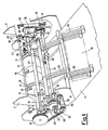
- the illustrated device comprises essentially a frame, represented schematically by the pair of shoulders 11, on the top of which a container means indicated overall by 12 is disposed, in which single sheets 13 or the like are stacked one on the other.
- a container means indicated overall by 12 In the lower part opposite the container means 12 there is an exit table represented schematically by 14 and consisting for example of a conveyor (not shown) on which a continuous film of thermoplastic material (also not shown) is fed, to be used for the packaging.
- a central drive means (not shown), of which only a motion transmission chain 15 deriving from it is shown, provides for the entire movement of all the parts of the device according to the invention. More precisely, the chain 15, engaged about a sprocket 20, rotates a central drive shaft 16 on which the sprocket 20 is keyed and which is supported between the shoulders 11 to firstly rotate a lower conveyor band consisting essentially of a first series of belts 17.
- a lower conveyor band consisting essentially of a first series of belts 17.
- two belts 17 are shown purely by way of example and to allow better understanding of the drawing, but are usually more numerous.
- the belts 17 accompany each other spaced apart and parallel, and in their initial portion are positioned essentially below the container means 12.
- the belts 17 pass within recesses 18 provided in a pair of drums 19 rigid coaxially with the central drive shaft 16. In this manner the drums 19, which are of greater diameter than the recesses 18 and the portions of the belts 17 contained within them, enter into engagement with a presser roller 27 which is described in detail hereinafter.
- the drive shaft 16 carries a composite belt transmission by which it rotates a series of means which constitute the device of the invention.
- a first toothed pulley 21 keyed onto the drive shaft 16 rotates a belt 22 provided with teeth on both its surfaces.
- the teeth on the outer surface of the belt 22 engage a second pulley 23 provided on a second shaft 24 and free to rotate on interposed bearings.
- the second pulley 23 is rigidly connected to a third pulley 25 of greater diameter, which is also free to rotate on interposed bearings and with which there engage a second toothed belt 26 to rotate a presser roller 27 and a third toothed belt 28 to rotate an upper presser band consisting of a second series of belts 29.
- the presser roller 27 and the first series of belts 17 essentially form the said extraction means for the sheet 13, the presence of the drums 19 completing or improving said extraction means in a preferred embodiment such as that described.
- the second series of belts 29 in cooperation with the terminal portion of the first series of belts 17 form said evacuation means for the sheet 13.
- a pair of levers 31 supporting the presser roller 27 are fixed on the second shaft 24 by end clamps 30. It can also be seen that an extension of one end of a shaft 32 connected to the roller 27 carries a further toothed pulley 33 which receives its motion from the second toothed belt 26, to rotate the roller 27. Because of the particular arrangement and rocking motion of the presser roller 27 which is explained hereinafter, the second toothed belt 26 is provided with a rotary tensioning device 34 rotatably supported on a right-angled lever 35 rigidly secured to one end of the second shaft 24 by a locking clamp 36.
- the device according to the invention is provided with a first cam mechanism which causes the presser roller to move from a first position detached from the first series of belts 17 or rather from the drums 19 to a second position in engagement with them.
- This first cam mechanism consists essentially of a first cam 37 keyed onto the drive shaft 16 and on which an elastically yieldable articulated lever system 38 acts to transform the rotational motion of the cam into rocking motion of an end lever 39 locked on the second shaft 24. In this manner the second shaft 24 is subjected to a rocking movement which is consequently transmitted to the presser roller 27 supported on it.
- An elastic element such as a spring 40 is secured at one end to the shoulder 11 and at its other end to a free end of a further lever 41 rigid with the free end of the second shaft 24.
- the spring 40 therefore exerts traction on the lever 41 which by rotating the second shaft 24 urges the presser roller in the direction against the first series of belts 17, ie against the drums 19.
- the device of the invention is also provided with means for separating the sheets 13 from the bottom of the container means 12. More specifically, in a position corresponding with an aperture 42 provided in the base of the container means 12 there is a series of sucker elements 43 supported on a third shaft 44 arranged transverse to the shoulders 11 and caused to rock by a second cam mechanism provided at one end.
- the second cam mechanism comprises a second cam 45 keyed onto the drive shaft 16, and on which a further elastically yieldable articulated lever 46 system acts to transform the rotational motion into rocking motion of an end lever 47 locked on the third shaft 44.
- the third shaft is subjected to a rocking movement which causes the sucker elements 43 to move from a first retracted position below the conveyor band, ie below the first series of belts and below the outer surface of the drums, to a second position corresponding with the aperture 42 of the container means where they engage an initial portion of the sheet 13.
- an elastic element such as a spring 48 is provided suitably secured at one end to the shoulder and at its other end to a further lever 49 of the articulated lever system 46 to ensure engagement of the sucker elements on the initial portion of the sheet 13.
- the two cam mechanisms 37, 38 and 45, 46 determine the position shown in Figure 3 in which the presser roller 27 is raised from the belts 17 and drums 19, and the suckers 43 are in contact with an initial portion of a sheet 13 at the aperture 42 in the container means 12.
- first cam mechanism 37, 38 causes the presser roller to swing onto the initial portion of the sheet 13 to retain it between the presser roller and the outer surfaces of the drums 19 ( Figure 5).
- suckers 43 disengage in known manner to allow the further rotation of the central drive shaft 16 to advance the sheet 13, which being supported only at the exit of the drums 19 on the belts 17 moves until it becomes inserted between the belts 17 and the belts 29 of the upper presser band.
- the cycle then continues with the further extraction of a sheet and its further feed onto the continuous film of thermoplastic material of the packaging machine.
- the particular structure of the centrally controlled automatic feed device of the present invention and its positive movement transmission ensure perfect synchronism between the various speeds by proper choice of the toothed pulley dimensions and cam contours based on the various transmission ratios required.
- This type of transmission also ensures correct transmission of rotation to the presser roller by virtue of having provided a rotary tensioning device which rocks rigidly with the rocking of the second drive shaft supporting the presser roller and which consequently maintains correct tensioning of the toothed belt in the various positions.
- the particular structure of the extraction means formed from the presser roller and the lower conveyor band and the further presence of the drums ensure reliable extraction of the sheet previously separated from the container means, and at the same time prevents any damage to the sheet.
Landscapes
- Engineering & Computer Science (AREA)
- Mechanical Engineering (AREA)
- Sheets, Magazines, And Separation Thereof (AREA)
- Supplying Of Containers To The Packaging Station (AREA)
- Controlling Rewinding, Feeding, Winding, Or Abnormalities Of Webs (AREA)
- Basic Packing Technique (AREA)
Applications Claiming Priority (2)
| Application Number | Priority Date | Filing Date | Title |
|---|---|---|---|
| IT1963590 | 1990-03-09 | ||
| IT19635A IT1239374B (it) | 1990-03-09 | 1990-03-09 | Dispositivo automatico a comando centralizzato di alimentazione di fogli singoli e similari in una macchina confezionatrice |
Publications (3)
| Publication Number | Publication Date |
|---|---|
| EP0445878A2 true EP0445878A2 (de) | 1991-09-11 |
| EP0445878A3 EP0445878A3 (en) | 1993-01-27 |
| EP0445878B1 EP0445878B1 (de) | 1996-10-09 |
Family
ID=11159935
Family Applications (1)
| Application Number | Title | Priority Date | Filing Date |
|---|---|---|---|
| EP91200448A Expired - Lifetime EP0445878B1 (de) | 1990-03-09 | 1991-03-02 | Zentral betätigte automatische Vorrichtung zur Zuführung einzelner Blätter oder dergleichen in einer Verpackungsmaschine |
Country Status (10)
| Country | Link |
|---|---|
| US (1) | US5125638A (de) |
| EP (1) | EP0445878B1 (de) |
| JP (1) | JP3016886B2 (de) |
| AT (1) | ATE143907T1 (de) |
| CA (1) | CA2037640C (de) |
| DE (1) | DE69122527T2 (de) |
| DK (1) | DK0445878T3 (de) |
| ES (1) | ES2093069T3 (de) |
| GR (1) | GR3021852T3 (de) |
| IT (1) | IT1239374B (de) |
Cited By (1)
| Publication number | Priority date | Publication date | Assignee | Title |
|---|---|---|---|---|
| CN102070031A (zh) * | 2010-12-14 | 2011-05-25 | 彭智勇 | 从泡沫塑料薄板叠垛底部连续单张抽取薄板的方法及装置 |
Families Citing this family (4)
| Publication number | Priority date | Publication date | Assignee | Title |
|---|---|---|---|---|
| US5441248A (en) * | 1994-05-13 | 1995-08-15 | Jay L. Kristola | Feeding mechanism |
| ITMI20040833A1 (it) * | 2004-04-27 | 2004-07-27 | Sitma Spa | Procedimento di alimentazione di singoli prodotti in foglio ad un trasportatore a spintori in una apparecchiatura di confezionamento di prodotti editoriali |
| WO2019176933A1 (ja) * | 2018-03-14 | 2019-09-19 | 株式会社Nbcメッシュテック | メッシュ部材、篩及びスクリーン版 |
| CN109896092A (zh) * | 2019-03-28 | 2019-06-18 | 无锡恒泰电缆机械制造有限公司 | 自动放置电线圈标签装置 |
Family Cites Families (11)
| Publication number | Priority date | Publication date | Assignee | Title |
|---|---|---|---|---|
| GB191424307A (en) * | 1913-12-18 | 1915-04-15 | Molins Machine Co Ltd | Method of and Means for Removing Sheets severally from the Bottom of a Pile. |
| US1806102A (en) * | 1928-09-20 | 1931-05-19 | Harry G Traver | Amusement ride |
| US2550079A (en) * | 1948-09-15 | 1951-04-24 | Remington Rand Inc | Wiring unit |
| GB829518A (en) * | 1957-04-04 | 1960-03-02 | Ertma S A | A new or improved apparatus for the separation of sheets from a pile |
| CH475095A (de) * | 1967-05-25 | 1969-07-15 | Martini Buchbindermaschf | Verfahren und Maschine zum Zusammentragen ungefalzter und gefalzter Bogen |
| US3497205A (en) * | 1967-09-07 | 1970-02-24 | Halm Instrument Co | Sheet feeding means |
| US4155546A (en) * | 1977-07-27 | 1979-05-22 | Itek Corporation | Bottom sheet feeding apparatus |
| JPS5748543A (en) * | 1980-09-04 | 1982-03-19 | Laurel Bank Mach Co Ltd | Attraction and drawing-out apparatus of paper sheet processing machine |
| US4369962A (en) * | 1981-02-17 | 1983-01-25 | Murray Spiro | Apparatus for feeding sheets |
| JPS57184036A (en) * | 1981-05-06 | 1982-11-12 | Laurel Bank Mach Co Ltd | Conveying mechanism in separate conveyance device for bank note |
| DE3220237C2 (de) * | 1982-05-28 | 1984-06-28 | Agfa-Gevaert Ag, 5090 Leverkusen | Vereinzelungseinrichtung für blattförmige Kopieträger |
-
1990
- 1990-03-09 IT IT19635A patent/IT1239374B/it active IP Right Grant
-
1991
- 1991-03-01 US US07/664,542 patent/US5125638A/en not_active Expired - Lifetime
- 1991-03-02 AT AT91200448T patent/ATE143907T1/de not_active IP Right Cessation
- 1991-03-02 DE DE69122527T patent/DE69122527T2/de not_active Expired - Fee Related
- 1991-03-02 EP EP91200448A patent/EP0445878B1/de not_active Expired - Lifetime
- 1991-03-02 ES ES91200448T patent/ES2093069T3/es not_active Expired - Lifetime
- 1991-03-02 DK DK91200448.8T patent/DK0445878T3/da active
- 1991-03-06 CA CA002037640A patent/CA2037640C/en not_active Expired - Fee Related
- 1991-03-08 JP JP3043842A patent/JP3016886B2/ja not_active Expired - Lifetime
-
1996
- 1996-12-02 GR GR960403262T patent/GR3021852T3/el unknown
Cited By (1)
| Publication number | Priority date | Publication date | Assignee | Title |
|---|---|---|---|---|
| CN102070031A (zh) * | 2010-12-14 | 2011-05-25 | 彭智勇 | 从泡沫塑料薄板叠垛底部连续单张抽取薄板的方法及装置 |
Also Published As
| Publication number | Publication date |
|---|---|
| IT1239374B (it) | 1993-10-20 |
| IT9019635A0 (it) | 1990-03-09 |
| IT9019635A1 (it) | 1991-09-09 |
| JPH04213526A (ja) | 1992-08-04 |
| DK0445878T3 (da) | 1997-02-17 |
| DE69122527T2 (de) | 1997-03-20 |
| CA2037640C (en) | 2001-08-28 |
| CA2037640A1 (en) | 1991-09-10 |
| DE69122527D1 (de) | 1996-11-14 |
| JP3016886B2 (ja) | 2000-03-06 |
| EP0445878B1 (de) | 1996-10-09 |
| ATE143907T1 (de) | 1996-10-15 |
| GR3021852T3 (en) | 1997-03-31 |
| EP0445878A3 (en) | 1993-01-27 |
| US5125638A (en) | 1992-06-30 |
| ES2093069T3 (es) | 1996-12-16 |
Similar Documents
| Publication | Publication Date | Title |
|---|---|---|
| EP0748277B1 (de) | Pappenzufuhreinheit | |
| US3825247A (en) | Rotary gathering machine | |
| GB1584109A (en) | Apparatus for destacking flexible flat structures | |
| US4988086A (en) | Apparatus and method for forming sheet material assemblages | |
| US2313100A (en) | Sheet feeding mechanism | |
| JPS5938131B2 (ja) | ふた付き袋を分離して充填機に送る装置 | |
| EP0445878B1 (de) | Zentral betätigte automatische Vorrichtung zur Zuführung einzelner Blätter oder dergleichen in einer Verpackungsmaschine | |
| US4976420A (en) | Method for gathering signatures and a gathering machine for working the method | |
| US4768770A (en) | Signature feeder for a bookbinding machine | |
| GB1597996A (en) | Production of foldable boxes | |
| US4465269A (en) | Printing substrate handling, particularly sheet folding apparatus | |
| US4383683A (en) | Apparatus for separating the bottom sheet of a stack or sheets | |
| EP0738682B1 (de) | Vorrichtung zum schnellen Zuführen von Beilage-Bögen zu einer Überschiebeeinrichtung einer Verpackungsmachine | |
| JPH034468B2 (de) | ||
| EP0526946B1 (de) | Vorrichtung zum vereinzelten Zuführen von Blättern oder dergleichen zu einer Verpackungs- oder Etikettiermaschine | |
| US4068582A (en) | Automatically controlled numbering machine | |
| US20200180340A1 (en) | An Improved Round Corner Cutting Machine for Exercise Note Books | |
| US3688472A (en) | Transfer apparatus for a packing machine | |
| US2905067A (en) | Cutting and creasing press | |
| US3667663A (en) | Feeder unit | |
| GB2119767A (en) | Apparatus for opening multi- layered folded sheets | |
| US3384366A (en) | Outfeed mechanism | |
| GB763916A (en) | A machine for feeding sheet blanks to box or carton forming machines | |
| US7320463B2 (en) | Device for feeding a processing section | |
| JPS59182131A (ja) | 紙葉類分離装置 |
Legal Events
| Date | Code | Title | Description |
|---|---|---|---|
| PUAI | Public reference made under article 153(3) epc to a published international application that has entered the european phase |
Free format text: ORIGINAL CODE: 0009012 |
|
| AK | Designated contracting states |
Kind code of ref document: A2 Designated state(s): AT BE CH DE DK ES FR GB GR IT LI LU NL SE |
|
| PUAL | Search report despatched |
Free format text: ORIGINAL CODE: 0009013 |
|
| AK | Designated contracting states |
Kind code of ref document: A3 Designated state(s): AT BE CH DE DK ES FR GB GR IT LI LU NL SE |
|
| RHK1 | Main classification (correction) |
Ipc: B65H 3/08 |
|
| 17P | Request for examination filed |
Effective date: 19930710 |
|
| 17Q | First examination report despatched |
Effective date: 19940620 |
|
| GRAG | Despatch of communication of intention to grant |
Free format text: ORIGINAL CODE: EPIDOS AGRA |
|
| GRAH | Despatch of communication of intention to grant a patent |
Free format text: ORIGINAL CODE: EPIDOS IGRA |
|
| GRAH | Despatch of communication of intention to grant a patent |
Free format text: ORIGINAL CODE: EPIDOS IGRA |
|
| GRAA | (expected) grant |
Free format text: ORIGINAL CODE: 0009210 |
|
| AK | Designated contracting states |
Kind code of ref document: B1 Designated state(s): AT BE CH DE DK ES FR GB GR IT LI LU NL SE |
|
| REF | Corresponds to: |
Ref document number: 143907 Country of ref document: AT Date of ref document: 19961015 Kind code of ref document: T |
|
| ITF | It: translation for a ep patent filed | ||
| REF | Corresponds to: |
Ref document number: 69122527 Country of ref document: DE Date of ref document: 19961114 |
|
| REG | Reference to a national code |
Ref country code: CH Ref legal event code: NV Representative=s name: A. BRAUN, BRAUN, HERITIER, ESCHMANN AG PATENTANWAE |
|
| REG | Reference to a national code |
Ref country code: ES Ref legal event code: FG2A Ref document number: 2093069 Country of ref document: ES Kind code of ref document: T3 |
|
| ET | Fr: translation filed | ||
| REG | Reference to a national code |
Ref country code: DK Ref legal event code: T3 |
|
| REG | Reference to a national code |
Ref country code: GR Ref legal event code: FG4A Free format text: 3021852 |
|
| PLBE | No opposition filed within time limit |
Free format text: ORIGINAL CODE: 0009261 |
|
| STAA | Information on the status of an ep patent application or granted ep patent |
Free format text: STATUS: NO OPPOSITION FILED WITHIN TIME LIMIT |
|
| 26N | No opposition filed | ||
| REG | Reference to a national code |
Ref country code: GB Ref legal event code: IF02 |
|
| PGFP | Annual fee paid to national office [announced via postgrant information from national office to epo] |
Ref country code: DE Payment date: 20070222 Year of fee payment: 17 |
|
| PGFP | Annual fee paid to national office [announced via postgrant information from national office to epo] |
Ref country code: LU Payment date: 20070228 Year of fee payment: 17 Ref country code: GB Payment date: 20070228 Year of fee payment: 17 |
|
| PGFP | Annual fee paid to national office [announced via postgrant information from national office to epo] |
Ref country code: CH Payment date: 20070301 Year of fee payment: 17 |
|
| PGFP | Annual fee paid to national office [announced via postgrant information from national office to epo] |
Ref country code: SE Payment date: 20070307 Year of fee payment: 17 |
|
| PGFP | Annual fee paid to national office [announced via postgrant information from national office to epo] |
Ref country code: AT Payment date: 20070313 Year of fee payment: 17 |
|
| PGFP | Annual fee paid to national office [announced via postgrant information from national office to epo] |
Ref country code: DK Payment date: 20070315 Year of fee payment: 17 |
|
| PGFP | Annual fee paid to national office [announced via postgrant information from national office to epo] |
Ref country code: ES Payment date: 20070417 Year of fee payment: 17 |
|
| PGFP | Annual fee paid to national office [announced via postgrant information from national office to epo] |
Ref country code: BE Payment date: 20070514 Year of fee payment: 17 |
|
| PGFP | Annual fee paid to national office [announced via postgrant information from national office to epo] |
Ref country code: GR Payment date: 20070214 Year of fee payment: 17 |
|
| PGFP | Annual fee paid to national office [announced via postgrant information from national office to epo] |
Ref country code: FR Payment date: 20070308 Year of fee payment: 17 |
|
| PGFP | Annual fee paid to national office [announced via postgrant information from national office to epo] |
Ref country code: NL Payment date: 20080303 Year of fee payment: 18 |
|
| REG | Reference to a national code |
Ref country code: CH Ref legal event code: PFA Owner name: SITMA S.P.A. Free format text: SITMA S.P.A.#VIA VIGNOLESE, 85#41057 SPILAMBERTO (MODENA) (IT) -TRANSFER TO- SITMA S.P.A.#VIA VIGNOLESE, 85#41057 SPILAMBERTO (MODENA) (IT) |
|
| BERE | Be: lapsed |
Owner name: SITMA S.P.A. Effective date: 20080331 |
|
| REG | Reference to a national code |
Ref country code: CH Ref legal event code: PL |
|
| REG | Reference to a national code |
Ref country code: DK Ref legal event code: EBP |
|
| EUG | Se: european patent has lapsed | ||
| GBPC | Gb: european patent ceased through non-payment of renewal fee |
Effective date: 20080302 |
|
| PG25 | Lapsed in a contracting state [announced via postgrant information from national office to epo] |
Ref country code: AT Free format text: LAPSE BECAUSE OF NON-PAYMENT OF DUE FEES Effective date: 20080302 |
|
| REG | Reference to a national code |
Ref country code: FR Ref legal event code: ST Effective date: 20081125 |
|
| PG25 | Lapsed in a contracting state [announced via postgrant information from national office to epo] |
Ref country code: LI Free format text: LAPSE BECAUSE OF NON-PAYMENT OF DUE FEES Effective date: 20080331 Ref country code: SE Free format text: LAPSE BECAUSE OF NON-PAYMENT OF DUE FEES Effective date: 20080303 Ref country code: CH Free format text: LAPSE BECAUSE OF NON-PAYMENT OF DUE FEES Effective date: 20080331 Ref country code: DE Free format text: LAPSE BECAUSE OF NON-PAYMENT OF DUE FEES Effective date: 20081001 |
|
| PG25 | Lapsed in a contracting state [announced via postgrant information from national office to epo] |
Ref country code: BE Free format text: LAPSE BECAUSE OF NON-PAYMENT OF DUE FEES Effective date: 20080331 |
|
| PG25 | Lapsed in a contracting state [announced via postgrant information from national office to epo] |
Ref country code: DK Free format text: LAPSE BECAUSE OF NON-PAYMENT OF DUE FEES Effective date: 20080331 Ref country code: FR Free format text: LAPSE BECAUSE OF NON-PAYMENT OF DUE FEES Effective date: 20080331 |
|
| REG | Reference to a national code |
Ref country code: ES Ref legal event code: FD2A Effective date: 20080303 |
|
| PG25 | Lapsed in a contracting state [announced via postgrant information from national office to epo] |
Ref country code: GB Free format text: LAPSE BECAUSE OF NON-PAYMENT OF DUE FEES Effective date: 20080302 Ref country code: GR Free format text: LAPSE BECAUSE OF NON-PAYMENT OF DUE FEES Effective date: 20081002 |
|
| PG25 | Lapsed in a contracting state [announced via postgrant information from national office to epo] |
Ref country code: ES Free format text: LAPSE BECAUSE OF NON-PAYMENT OF DUE FEES Effective date: 20080303 |
|
| NLV4 | Nl: lapsed or anulled due to non-payment of the annual fee |
Effective date: 20091001 |
|
| PG25 | Lapsed in a contracting state [announced via postgrant information from national office to epo] |
Ref country code: NL Free format text: LAPSE BECAUSE OF NON-PAYMENT OF DUE FEES Effective date: 20091001 |
|
| PGFP | Annual fee paid to national office [announced via postgrant information from national office to epo] |
Ref country code: IT Payment date: 20100309 Year of fee payment: 20 |
|
| PG25 | Lapsed in a contracting state [announced via postgrant information from national office to epo] |
Ref country code: LU Free format text: LAPSE BECAUSE OF NON-PAYMENT OF DUE FEES Effective date: 20080302 |