EP3630574B1 - Bogie pour véhicule ferroviaire - Google Patents
Bogie pour véhicule ferroviaire Download PDFInfo
- Publication number
- EP3630574B1 EP3630574B1 EP18720204.9A EP18720204A EP3630574B1 EP 3630574 B1 EP3630574 B1 EP 3630574B1 EP 18720204 A EP18720204 A EP 18720204A EP 3630574 B1 EP3630574 B1 EP 3630574B1
- Authority
- EP
- European Patent Office
- Prior art keywords
- bogie
- bogie according
- primary suspension
- suspension means
- wheelset
- Prior art date
- Legal status (The legal status is an assumption and is not a legal conclusion. Google has not performed a legal analysis and makes no representation as to the accuracy of the status listed.)
- Active
Links
Images



Classifications
-
- B—PERFORMING OPERATIONS; TRANSPORTING
- B61—RAILWAYS
- B61F—RAIL VEHICLE SUSPENSIONS, e.g. UNDERFRAMES, BOGIES OR ARRANGEMENTS OF WHEEL AXLES; RAIL VEHICLES FOR USE ON TRACKS OF DIFFERENT WIDTH; PREVENTING DERAILING OF RAIL VEHICLES; WHEEL GUARDS, OBSTRUCTION REMOVERS OR THE LIKE FOR RAIL VEHICLES
- B61F3/00—Types of bogies
- B61F3/02—Types of bogies with more than one axle
- B61F3/04—Types of bogies with more than one axle with driven axles or wheels
-
- B—PERFORMING OPERATIONS; TRANSPORTING
- B61—RAILWAYS
- B61F—RAIL VEHICLE SUSPENSIONS, e.g. UNDERFRAMES, BOGIES OR ARRANGEMENTS OF WHEEL AXLES; RAIL VEHICLES FOR USE ON TRACKS OF DIFFERENT WIDTH; PREVENTING DERAILING OF RAIL VEHICLES; WHEEL GUARDS, OBSTRUCTION REMOVERS OR THE LIKE FOR RAIL VEHICLES
- B61F5/00—Constructional details of bogies; Connections between bogies and vehicle underframes; Arrangements or devices for adjusting or allowing self-adjustment of wheel axles or bogies when rounding curves
- B61F5/26—Mounting or securing axle-boxes in vehicle or bogie underframes
- B61F5/28—Axle-boxes integral with, or directly secured to, vehicle or bogie underframes
-
- B—PERFORMING OPERATIONS; TRANSPORTING
- B61—RAILWAYS
- B61F—RAIL VEHICLE SUSPENSIONS, e.g. UNDERFRAMES, BOGIES OR ARRANGEMENTS OF WHEEL AXLES; RAIL VEHICLES FOR USE ON TRACKS OF DIFFERENT WIDTH; PREVENTING DERAILING OF RAIL VEHICLES; WHEEL GUARDS, OBSTRUCTION REMOVERS OR THE LIKE FOR RAIL VEHICLES
- B61F5/00—Constructional details of bogies; Connections between bogies and vehicle underframes; Arrangements or devices for adjusting or allowing self-adjustment of wheel axles or bogies when rounding curves
- B61F5/50—Other details
- B61F5/52—Bogie frames
Definitions
- the invention relates to a bogie for rail vehicles, in particular a driven bogie, having at least two wheel sets with wheels and a wheel set shaft, a frame with at least two longitudinal members and at least one cross member, and first primary suspension systems, suitable for cushioning the wheel sets relative to the frame, and wheel set bearings that Store wheel sets in the frame.
- Conventional bogies have a running gear frame with two longitudinal beams, which usually run over the wheel set bearings, and bearing supports, which are held on the longitudinal beam by primary springs and axle links. Thus, the frame is sprung in relation to the wheel sets. Secondary springs are arranged between the frame of the bogie and the car body of the rail vehicle, which cushion the bogie relative to the car body.
- An example of such bogies is in WO 2016/045864 A1 shown.
- the wheel bearing is located on a bearing carrier, which is attached to the longitudinal member of the frame via a wheel set guide and which is cushioned in relation to the frame via the primary suspension, designed as a spiral spring.
- a major disadvantage of the previously known bogies is that a lot of space is required for the primary suspension and the bearing bracket.
- the drive power is transferred from the motor to one of the wheel sets via a final drive and a clutch.
- the final drive is usually located inside the wheels.
- a lot of coordination is required in the arrangement - between the engine, transmission, frame, primary suspension and wheelset bearings.
- a three-axle powered bogie is disclosed.
- the wheelset bearing is attached to a bearing carrier that Is cushioned primary springs in the form of spiral springs compared to the longitudinal members of the frame.
- the traction motor is provided on the bogie.
- the engine and the final drive are attached to the outside of one of the side members as a traction unit.
- a large amount of space is required, which is disadvantageous and which further restricts the usable low-floor portion between the wheels due to an internal longitudinal member.
- the EP 0814993 A1 describes a bogie with longitudinal beams as a self-supporting housing that enclose electric drives, which each drive two individual wheels.
- the object of the invention is now to provide a space-saving bogie with good suspension.
- the bogie according to the invention is characterized in that the longitudinal beams are each designed as a self-supporting housing from which the respective first primary suspension systems and the wheel set bearings of the two wheel sets are essentially enclosed, with the first primary suspension systems being arranged radially inside the respective wheel set bearings and with the first primary suspension systems being designed in such a way that during operation at least over one, in particular over at least one of the primary suspension systems for each wheel set drive torque can be transferred. That is, there is a left side rail surrounding the left side axle box and first primary suspension and a right side rail surrounding the right side axle box and first primary suspension.
- the main advantage of the solution according to the invention is that by designing the longitudinal member as a self-supporting housing and the first primary springs and wheel set bearings integrated therein, an enormous amount of space and height can be saved. This is particularly interesting for low-floor vehicles.
- the unsprung mass on the primary side, i.e. on the wheelset side is very small. This is good for smooth running behavior and offers reduced susceptibility to vibration.
- the self-supporting housing forms the supporting structure of the bogie and must be designed so stable and torsion-resistant that it can absorb the weight and dynamic forces that occur. Due to the fact that the wheelset bearing and the first primary suspension are arranged in the side member within the supporting structure of the frame, which is designed like a housing, the installation space is optimally utilized. In relation to the wheel set bearings and the first primary suspensions, it is understood here by substantially enclosed that a substantial part thereof is surrounded by the housing that forms the supporting structure, in particular that the housing surrounds the wheel set bearings and the first primary suspensions along their perimeter.
- Another advantage of this design is that the wheel set bearings and the first primary suspension are better protected by the surrounding housing, for example from dirt or damage.
- the first primary springs are designed in such a way that they can transmit drive torque, ie torque to the wheelsets. It is possible to also install the first primary suspension in a very space-saving manner and in particular without the need for additional height.
- the bearing supports can be whole omitted.
- several rubber elements which are arranged as wedge segments between corresponding radial driver wedges, can be used. However, differently shaped rubber elements can also be used for this.
- the bogie according to the invention does not necessarily have to be a driven bogie. In particular, not all wheel sets of the bogie have to be driven. And in particular, torque does not have to be transmitted via both sides of a wheelset.
- second primary springs can be present, which also cushion the wheel sets relative to the frame.
- an even better cushioning of oscillations and vibrations can be achieved, which significantly increases the service life of the components.
- the effective diameter of the second primary springs is greater than the effective diameter of the first primary springs. This improves the spring effect.
- These second primary springs are also designed in such a way that drive torque can be transmitted via them.
- Each wheel set preferably has such a second primary suspension on each side. This arrangement achieves a symmetrical behavior of the bogie.
- the second primary springs can be arranged in the self-supporting housing of the side member. However, they can just as well be provided outside of the longitudinal member. The second option offers the possibility of realizing a larger effective diameter for the second primary suspension without the self-supporting housing becoming too large.
- first primary springs are arranged concentrically to the axle.
- concentric means that they are arranged symmetrically around the axle or its extension.
- second primary springs in the above sense are also arranged concentrically to the wheel set axle.
- the second primary springs can be designed as so-called wedge pack clutches, in which wedge-shaped rubber packs are arranged between radial driver elements of the hollow shaft.
- the first primary suspension and the wheel set bearing are each arranged around a stub shaft which is attached to the outside of the wheel as an extension of the wheel set shaft.
- the wheel set With a corresponding screw connection between the stub shaft and the wheel or wheelset shaft, the wheel set can be separated and dismantled very easily and quickly from the stub shaft and the wheel set bearing.
- this screw connection can be made via a central screw in the stub shaft.
- the connection can also be made using socket pins.
- the power and torque can be transmitted via suitable clutches.
- a Hirth tooth system on the wheel and on the stub shaft, which mesh, is particularly suitable for this.
- the first primary springs are arranged radially within the wheelset bearings.
- the overall unit is still more compact and is very easy to change.
- the unsprung mass on the primary side of the wheel set is smaller than in previously known bogies.
- the result is a very compact design with very good spring properties and a long service life for the components.
- the first primary springs can each be arranged in a hollow shaft, with the hollow shafts being mounted in the housing via the wheel set bearings.
- the first and the second primary springs preferably act side by side, that is, the second primary spring acts like the first primary spring between the hollow shaft and the stub shaft or the wheel.
- the first primary springs are designed as wedge-shaped rubber elements which are preferably arranged between radial driver elements which are part of the hollow shaft and/or are rigidly connected to the hollow shaft.
- each wheel set has at least one such hollow shaft as mentioned above.
- At least one of the hollow shafts is connected to a brake disk, in particular if at least one hollow shaft is connected to a brake disk on each wheelset.
- the brake disc is particularly preferably provided on the outside, ie on the side facing away from the wheel. This in turn enables a particularly space-saving design and the attachment to the hollow shaft means that the wheel set can still be easily dismantled.
- the braking force can take effect before the primary suspension in the drive train. With several brake discs per bogie, the braking force can also be better distributed.
- the brake disc can also be connected directly to one of the stub shafts or to the wheelset. As a result, the braking force is applied directly to the primary side.
- a gear can be present in at least one: i, preferably in both, self-supporting housings.
- the gearbox increases or decreases the speed and transmits drive torque to the wheelsets.
- a transmission located in the housing is also considered when only one transmission stage of a multi-stage transmission is present in the self-supporting housing.
- the gear can be designed as a bevel gear or as a spur gear or as a combination of both.
- a two-stage gearbox offers a higher reduction ratio without the need for oversized gears.
- the drive torque can be transmitted from a longitudinally arranged motor to the transverse wheel sets by means of a bevel gear or a bevel-spur gear.
- a traction motor can be present in at least one, preferably in both, self-supporting housings.
- a gearbox located in the housing a very efficient, integrated, driven bogie can be created.
- the entire mechanical drive part is housed and protected in the housing-like side member. If two wheelsets are driven and there is an integrated drive train in each side member, smaller motors and gearboxes can be used, which offers advantages when integrated into the housing. In addition, much less coordination between the components is necessary, which simplifies the design.
- the bogie according to the invention is improved even further with a power converter integrated into the self-supporting housing. This enables a fully integrated traction unit protected in the housing on the bogie. This means that very short current bridges are possible, which significantly reduces the overall cabling effort.
- the two drive trains consisting of the traction motor and the gear, optionally also with a power converter, are arranged point-symmetrically to one another on the two sides of the bogie. This means that one drive train drives the front wheel set and the other drive train drives the rear wheel set.
- the two side members are arranged essentially outside the space between the wheels. This leaves the entire gap, only somewhat limited by the relative turn-out angle of the bogie to the Car body, the possibility of a lowered floor of the car body.
- the possible low-floor proportion is therefore very high.
- secondary springs In particular two secondary springs per bogie.
- the secondary springs are preferably designed as spring assemblies and can each contain several springs.
- the invention can also be used for three-axle bogies.
- only one or two wheel sets can be driven and all wheel sets can be mounted and cushioned in the manner according to the invention.
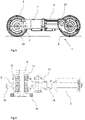
- FIGS 1a and 1b show schematically the essential structure of a bogie according to the invention 1 '.
- the frame has two self-supporting housings 2' as longitudinal members and a cross member 2a' which connects the two longitudinal members 2' to one another.
- the longitudinal beams 2' are located outside the space between the wheels 6.
- On the cross beam 2a' are the secondary springs 17, which cushion the bogie 1 relative to the car body, and a pivot socket, not shown, via which the bogie can be rotated with the car body but is load-bearing can be connected.
- a traction motor 3' is installed on each side of the self-supporting housing 2'.
- the traction motor 3' is fully or largely integrated in the side member 2'.
- a part of the motor 3' can also be integrated in the cross member 2a.
- the traction motor 3' transmits the drive torque to the wheel sets 5 via the drive shaft 15' and a single-stage bevel gear 21'.
- Part of the single-stage bevel gear 21' is a gear 14', which is designed here as a crown wheel and is connected directly to the hollow shaft 9' .
- the other pinion sits on the drive shaft 15'.
- the hollow shaft 9' is mounted in the housing 2' via the wheel bearing 12'.
- the two motors 3 ′ and the associated drive trains are arranged in a point-symmetrically mirrored manner such that one drives the front wheel set and one drives the rear wheel set 5 .
- a stub shaft 8' is fastened on each side, which is surrounded radially in each case by the first primary suspension 13'.
- the stub shaft 8' is rigid with the wheel 6, for example via a coupling, in particular a Hirth tooth system, and via additional screw connections tied together.
- the first primary suspension 13' is designed here with wedge-shaped rubber elements, between which there are driver elements of the hollow shaft.
- All first primary springs 13' are designed in the same way. Even if each wheel set 5 only transmits drive torque on one side. On the drive side, the drive torque is transmitted from the hollow shaft 9' via the first primary suspension 13' to the stub shaft 8' and thus to the wheelset 5, with simultaneous cushioning. On the side of the wheel set 5 remote from the drive, only the cushioning takes place via the first primary spring 13'.
- the wheel bearings 12' are dimensioned in such a way that they can enclose the first primary suspension 13'. The larger wheel bearings 12' offer additional advantages with regard to maintenance intervals and service life.
- Fig.2 another embodiment of a bogie 1 according to the invention is shown.
- the converters 4 required for this or essential parts thereof, such as power parts of the converter 4 are housed in the longitudinal beam 2, which is designed as a self-supporting housing.
- the drive trains are arranged point-symmetrically mirrored. Traction is transmitted from the drive shaft 15 of the engine to the hollow shaft 9 via the gearbox 21 .
- the gear wheel 14 firmly connected to the hollow shaft is part of the transmission 21.
- the drive torque is transmitted to the stub shaft 8 via driver elements (not shown) of the hollow shaft and the first primary springs 13, which can be designed as wedge-shaped rubber packages.
- the first primary springs 13 are located radially inside the wheel set bearings 12 and together with them in the self-supporting housing of the side member 2.
- second primary springs 10 are provided, which have a larger effective diameter than the first primary springs 13 and serve to further increase the spring effect.
- the stub shaft 8 is rigidly connected to the wheel 6 via a coupling 16 with a Hirth toothing and preferably via screw connections.
- a central screw through the stub shaft 8 can be provided as a screw connection, or several screws distributed over the circumference can be used for attachment to the wheel.
- a brake disc 20 can be fastened to one or both wheelsets 5 on the outside of the stub shaft 8, on which the brake 11, which is fastened to the side member 2, can act.
- the cross member 2a also carries the pivot socket 18 and lateral anti-lift devices 19 for the car body.
- elements for longitudinal and lateral force transmission, damping devices and stabilizing elements can also be present.
- a very compact bogie can be created by the complete integration of both the wheel bearings 12 and the first primary springs 13 as well as the traction motor 3 and the power converter 4 in the side members 2 .
- the power converter 4 can also be arranged separately, ie outside of the side member 2 . be, the enclosed by the self-supporting housing 2 components are very well protected against damage and dirt. In addition, the mechanical and geometric coordination in the traction train is much easier.
- cooling devices that are used to cool the traction motor 3 and / or the converter 4 and on the Bogie can be provided.
- a common cooling device for the motor 3 and the power converter 4 can be present.
- Traction motor 3 and power converter 4 are integrated into the side member 2, which is designed as a self-supporting housing.
- the right-hand wheel set can be driven via the gearbox 21, which is also integrated.
- the brake 11 and the brake disc 20 can also be seen.
- the drive train 4 shows the drive train as a section.
- the drive torque is transmitted to the hollow shaft 9 via the mounted drive shaft 15 and the two-stage bevel-spur gear 21 .
- the pinion on the drive shaft 15 meshes with the bevel gear on the intermediate shaft and the spur gear on the intermediate shaft meshes with the gear wheel 14 on the hollow shaft. So the speed of the motor 3 can be stocky according to the requirements.
- the hollow shaft 9 is mounted in the housing of the side member (not shown) via the wheel bearings 12 .
- the rubber elements of the first primary suspension 13 are located inside the wheel bearings 12 and transmit the drive torque from the driver elements of the hollow shaft 9 (not visible in this illustration) to the stub shaft 8.
- the second primary suspension 10 which is designed as a wedge pack coupling with wedge-shaped rubber elements, Transfer drive torque from the hollow shaft 9 to the stub shaft 8.
- the power is preferably transmitted via Hirth gearing. Shown as an example is a central bore in the stub shaft 8 via which it can be fastened to the wheelset with a central screw.
- Fig.5 an example of a wheel set 5 of a bogie according to the invention can be seen.
- the axle 7 two wheels 6 are available.
- On the outside of the wheels 6 there are coupling elements 16 with Hirth teeth for connecting the stub shaft.
- the wheels 6 there may be holes for screwing to the stub shafts. This allows screwing from the inside of the wheels into the stub shafts.
Landscapes
- Engineering & Computer Science (AREA)
- Mechanical Engineering (AREA)
- Vehicle Body Suspensions (AREA)
- Arrangement Or Mounting Of Propulsion Units For Vehicles (AREA)
Claims (14)
- Bogie (1, 1') pour un véhicule ferroviaire, réalisé en particulier sous la forme d'un bogie entraîné, présentant au moins deux essieux montés (5) pourvus de roues (6) et d'un arbre d'essieu monté (7), un cadre pourvu d'au moins deux longerons (2, 2') et d'au moins une traverse (2a, 2a'), ainsi que des premiers systèmes de suspension primaires (13, 13') adaptés pour assurer la suspension des essieux montés (5) par rapport au cadre, et des paliers d'essieu monté (12, 12') qui logent les essieux montés (5) dans le cadre, les longerons étant respectivement réalisés sous la forme d'un logement autoporteur (2, 2') qui entoure les paliers d'essieu monté (12, 12') respectifs des deux essieux montés (5), dans lequel au moins un, de préférence pour chaque essieu monté (5) au moins l'un des premiers systèmes de suspension primaires (13, 13') est configuré de telle sorte qu'en cours de fonctionnement, un couple d'entraînement peut être transmis par celui-ci,
caractérisé en ce que les premiers systèmes de suspension primaires (13, 13') respectifs sont également entourés du logement autoporteur (2, 2'), et en ce que les premiers systèmes de suspension primaires (13, 13'), vus radialement, sont disposés à l'intérieur des paliers d'essieu monté (12, 12') respectifs. - Bogie selon la revendication 1, caractérisé en ce que des deuxièmes systèmes de suspension primaires (10), adaptés pour assurer la suspension des essieux montés (5) par rapport au cadre, sont prévus et sont configurés de telle sorte qu'en cours de fonctionnement, un couple d'entraînement peut être transmis par ceux-ci, chaque essieu monté présentant de préférence un deuxième système de suspension primaire (10) par côté.
- Bogie selon la revendication 2, caractérisé en ce que les deuxièmes systèmes de suspension primaires (10) sont réalisée sous forme d'accouplements à crabots.
- Bogie selon l'une quelconque des revendications précédentes, caractérisé en ce que les premiers systèmes de suspension primaires (13, 13') sont respectivement disposés dans un arbre creux (9, 9'), et les arbres creux (9, 9') respectifs sont logés dans le logement (2, 2') par l'intermédiaire des paliers d'essieu monté (12, 12').
- Bogie selon la revendication 4, caractérisé en ce que les premiers systèmes de suspension primaires (13, 13') présentent des éléments en caoutchouc en forme de clavette qui sont disposés entre des éléments d'entraînement qui font partie de l'arbre creux (9, 9') ou sont reliés à celui-ci.
- Bogie selon l'une quelconque des revendications 4 ou 5, caractérisé en ce qu'au moins l'un des arbres creux (9, 9') présente une roue dentée (14, 14') ou est relié à une roue dentée (14, 14') par l'intermédiaire de laquelle le couple provenant d'un moteur de traction (3, 3') peut être introduit.
- Bogie selon l'une quelconque des revendications 4 à 6, caractérisé en ce qu'un disque de frein (20) est fixé à au moins l'un des arbres creux (9, 9'), et en ce que sur au moins l'un des longerons (2, 2'), un frein est prévu qui peut agir sur le disque de frein (20).
- Bogie selon l'une quelconque des revendications précédentes, caractérisé en ce qu'un engrenage (21, 21') est prévu au moins dans un, de préférence dans les deux logements autoporteurs (2, 2'), l'engrenage (21, 21') étant réalisé de préférence sous la forme d'un engrenage conique ou d'un engrenage droit ou sous la forme d'un engrenage conique et droit.
- Bogie selon l'une quelconque des revendications précédentes, caractérisé en ce qu'un moteur de traction (3, 3') est prévu au moins dans un, de préférence dans les deux logements autoporteurs (2, 2').
- Bogie selon l'une quelconque des revendications précédentes, caractérisé en ce qu'au moins dans un, de préférence dans les deux logements autoporteurs (2, 2'), un convertisseur de puissance (4) est prévu ou des parties essentielles d'un convertisseur de puissance (4), en particulier des parties de puissance, sont prévues.
- Bogie selon l'une quelconque des revendications 9 ou 10, caractérisé en ce qu'un refroidissement pour le moteur de traction (3, 3') et/ou le convertisseur de puissance (4) est prévu, en particulier en ce qu'un refroidissement commun pour le moteur de traction (3, 3') et le convertisseur de puissance (4) est prévu.
- Bogie selon l'une quelconque des revendications précédentes, caractérisé en ce que respectivement un bout d'arbre (8, 8') est prévu sur lequel est disposé le système de suspension primaire (13, 13'), le bout d'arbre (8 ; 8') étant relié à l'essieu monté (5) par des vis et/ou des axes embrochables.
- Bogie selon l'une quelconque des revendications précédentes, caractérisé en ce que les deux longerons (2, 2') sont disposés substantiellement à l'extérieur de l'espace entre les roues (6) des essieux montés.
- Bogie selon l'une quelconque des revendications précédentes, caractérisé en ce que des systèmes de suspension secondaires (17) sont prévues qui assurent la suspension du cadre du bogie (1, 1') par rapport à la caisse.
Applications Claiming Priority (2)
| Application Number | Priority Date | Filing Date | Title |
|---|---|---|---|
| DE102017111190.5A DE102017111190A1 (de) | 2017-05-23 | 2017-05-23 | Drehgestell für Schienenfahrzeug |
| PCT/EP2018/060178 WO2018215147A1 (fr) | 2017-05-23 | 2018-04-20 | Bogie pour véhicule ferroviaire |
Publications (2)
| Publication Number | Publication Date |
|---|---|
| EP3630574A1 EP3630574A1 (fr) | 2020-04-08 |
| EP3630574B1 true EP3630574B1 (fr) | 2022-06-08 |
Family
ID=62063038
Family Applications (1)
| Application Number | Title | Priority Date | Filing Date |
|---|---|---|---|
| EP18720204.9A Active EP3630574B1 (fr) | 2017-05-23 | 2018-04-20 | Bogie pour véhicule ferroviaire |
Country Status (6)
| Country | Link |
|---|---|
| EP (1) | EP3630574B1 (fr) |
| CN (1) | CN110662685B (fr) |
| DE (1) | DE102017111190A1 (fr) |
| ES (1) | ES2923433T3 (fr) |
| PL (1) | PL3630574T3 (fr) |
| WO (1) | WO2018215147A1 (fr) |
Families Citing this family (4)
| Publication number | Priority date | Publication date | Assignee | Title |
|---|---|---|---|---|
| DE102019109971A1 (de) * | 2019-04-16 | 2020-10-22 | Voith Patent Gmbh | Antriebsstrang für ein Schienenfahrzeug |
| CN110155110B (zh) * | 2019-05-30 | 2021-02-02 | 中车青岛四方机车车辆股份有限公司 | 轨道车辆的转向架构架及转向架 |
| GB2603202B (en) * | 2021-02-02 | 2024-02-28 | The Council Of The City Of Coventry | Bogie for a light rail system |
| US20250001878A1 (en) * | 2021-02-02 | 2025-01-02 | The Council Of The City Of Coventry | Bogie for a light rail system |
Family Cites Families (13)
| Publication number | Priority date | Publication date | Assignee | Title |
|---|---|---|---|---|
| FR784029A (fr) * | 1934-11-03 | 1935-07-20 | Bogie pour automotrices électriques | |
| US4150627A (en) | 1974-04-03 | 1979-04-24 | Hamilton Neil King Paton | Self-contained frictionally damped resilient suspension system for railcars |
| DE4429889A1 (de) * | 1994-08-24 | 1996-02-29 | Bergische Stahlindustrie | Angetriebenes Fahrwerk für Schienenfahrzeuge |
| AT406569B (de) * | 1995-03-23 | 2000-06-26 | Elin Ebg Traction Gmbh | Fahrwerk für ein schienenfahrzeug, insbesondere niederflurstrassenbahn |
| WO2008070953A1 (fr) | 2006-12-15 | 2008-06-19 | National Steel Car Limited | Traverse danseuse |
| DE102011016906A1 (de) | 2011-04-13 | 2012-10-18 | Voith Patent Gmbh | Drehmomentenstütze sowie Drehgestell für ein Schienenfahrzeug |
| CN102407854A (zh) * | 2011-11-04 | 2012-04-11 | 张琳 | 轨道交通装置 |
| CN103273938A (zh) * | 2013-05-31 | 2013-09-04 | 南车株洲电力机车有限公司 | 一种转向架 |
| CN103587544A (zh) * | 2013-11-29 | 2014-02-19 | 米建军 | 一种轨道交通用减速装置 |
| FI125398B (fi) | 2013-12-11 | 2015-09-30 | Helsingin Kaupungin Liikennelaitos Liikelaitos | Teli ja vaunurakenne kiskokulkuneuvoa varten |
| AT516364A1 (de) | 2014-09-22 | 2016-04-15 | Siemens Ag Oesterreich | Fahrwerksrahmen mit Federtopf |
| FR3029879B1 (fr) | 2014-12-15 | 2017-01-13 | Alstom Transp Tech | Bogie motorise pour un vehicule ferroviaire a plancher surbaisse |
| DE102015211064A1 (de) | 2015-06-16 | 2016-12-22 | Bombardier Transportation Gmbh | Antriebsanordnung für Schienenfahrzeug, Schienenfahrzeug mit Antriebsanordnung sowie Verfahren zum Herstellen der Antriebsanordnung und des Schienenfahrzeugs |
-
2017
- 2017-05-23 DE DE102017111190.5A patent/DE102017111190A1/de not_active Withdrawn
-
2018
- 2018-04-20 CN CN201880033766.6A patent/CN110662685B/zh not_active Expired - Fee Related
- 2018-04-20 WO PCT/EP2018/060178 patent/WO2018215147A1/fr not_active Ceased
- 2018-04-20 PL PL18720204.9T patent/PL3630574T3/pl unknown
- 2018-04-20 EP EP18720204.9A patent/EP3630574B1/fr active Active
- 2018-04-20 ES ES18720204T patent/ES2923433T3/es active Active
Also Published As
| Publication number | Publication date |
|---|---|
| PL3630574T3 (pl) | 2022-09-05 |
| CN110662685B (zh) | 2021-05-18 |
| CN110662685A (zh) | 2020-01-07 |
| DE102017111190A1 (de) | 2018-11-29 |
| ES2923433T3 (es) | 2022-09-27 |
| EP3630574A1 (fr) | 2020-04-08 |
| WO2018215147A1 (fr) | 2018-11-29 |
Similar Documents
| Publication | Publication Date | Title |
|---|---|---|
| EP3630574B1 (fr) | Bogie pour véhicule ferroviaire | |
| EP3057843B1 (fr) | Boggie à essieu motorisé sur paliers | |
| EP2085284B1 (fr) | Dispositif de propulsion pour un véhicule ferroviaire | |
| EP0698540A1 (fr) | Train de roulement entraîné pour véhicules ferroviaires | |
| DE69708753T2 (de) | Angetriebene Achse mit unabhängig drehenden Rädern | |
| EP1685014B1 (fr) | Chassis propulse pour vehicules sur rails, en particulier pour boggies de vehicules a plancher bas | |
| EP0308616B1 (fr) | Groupe de propulsion pour véhicules ferroviaires | |
| EP2089263B1 (fr) | Train de roulement pour un véhicule ferroviaire | |
| EP2692607B1 (fr) | Châssis pour véhicule ferroviaire avec liaison fixe amovible entre les roues | |
| EP1532033B1 (fr) | Bogie moteur pour un vehicule sur rails | |
| DE69009076T2 (de) | Mehrzweck-Drehgestell für Schienenfahrzeuge. | |
| AT406569B (de) | Fahrwerk für ein schienenfahrzeug, insbesondere niederflurstrassenbahn | |
| EP1065122B1 (fr) | Essieu de roue folle pour véhicules ferroviaires | |
| DE102015222125A1 (de) | Antriebsanordnung für ein Schienenfahrzeug, Schienenfahrzeug mit der Antriebsanordnung und Verfahren zur Herstellung | |
| EP2939898B1 (fr) | Boggie pour véhicules sur rails ayant trois essieux montés | |
| WO2017093094A1 (fr) | Châssis de train de roulement pour un véhicule ferroviaire | |
| EP4122790B1 (fr) | Bogie à plancher surbaissé pourvu d'arbre d'essieu entrainé d'un côté | |
| DE4141463C2 (fr) | ||
| DE68905410T2 (de) | Antriebsdrehgestell fuer schienenfahrzeuge. | |
| DE102013210235A1 (de) | Drehmomentstütze für ein Schienenfahrzeug | |
| WO2024088896A1 (fr) | Organe de roulement pour véhicule ferroviaire et véhicule ferroviaire associé | |
| AT500277B1 (de) | Fahrwerk | |
| DE534732C (de) | Fahrgestell fuer Bahnfahrzeuge, insbesondere fuer Strassenbahntriebwagen | |
| AT517180B1 (de) | Fahrwerksrahmen für ein Schienenfahrzeug | |
| EP0870661A1 (fr) | Configuration d'entraínement dans bogies moteurs pour véhicles a plancher bas, notamment pour tramway destiné au transport urbain |
Legal Events
| Date | Code | Title | Description |
|---|---|---|---|
| STAA | Information on the status of an ep patent application or granted ep patent |
Free format text: STATUS: UNKNOWN |
|
| STAA | Information on the status of an ep patent application or granted ep patent |
Free format text: STATUS: THE INTERNATIONAL PUBLICATION HAS BEEN MADE |
|
| PUAI | Public reference made under article 153(3) epc to a published international application that has entered the european phase |
Free format text: ORIGINAL CODE: 0009012 |
|
| STAA | Information on the status of an ep patent application or granted ep patent |
Free format text: STATUS: REQUEST FOR EXAMINATION WAS MADE |
|
| 17P | Request for examination filed |
Effective date: 20200102 |
|
| AK | Designated contracting states |
Kind code of ref document: A1 Designated state(s): AL AT BE BG CH CY CZ DE DK EE ES FI FR GB GR HR HU IE IS IT LI LT LU LV MC MK MT NL NO PL PT RO RS SE SI SK SM TR |
|
| AX | Request for extension of the european patent |
Extension state: BA ME |
|
| DAV | Request for validation of the european patent (deleted) | ||
| DAX | Request for extension of the european patent (deleted) | ||
| GRAP | Despatch of communication of intention to grant a patent |
Free format text: ORIGINAL CODE: EPIDOSNIGR1 |
|
| STAA | Information on the status of an ep patent application or granted ep patent |
Free format text: STATUS: GRANT OF PATENT IS INTENDED |
|
| INTG | Intention to grant announced |
Effective date: 20220202 |
|
| GRAS | Grant fee paid |
Free format text: ORIGINAL CODE: EPIDOSNIGR3 |
|
| GRAA | (expected) grant |
Free format text: ORIGINAL CODE: 0009210 |
|
| STAA | Information on the status of an ep patent application or granted ep patent |
Free format text: STATUS: THE PATENT HAS BEEN GRANTED |
|
| AK | Designated contracting states |
Kind code of ref document: B1 Designated state(s): AL AT BE BG CH CY CZ DE DK EE ES FI FR GB GR HR HU IE IS IT LI LT LU LV MC MK MT NL NO PL PT RO RS SE SI SK SM TR |
|
| REG | Reference to a national code |
Ref country code: AT Ref legal event code: REF Ref document number: 1496745 Country of ref document: AT Kind code of ref document: T Effective date: 20220615 Ref country code: CH Ref legal event code: EP |
|
| REG | Reference to a national code |
Ref country code: DE Ref legal event code: R096 Ref document number: 502018009874 Country of ref document: DE |
|
| REG | Reference to a national code |
Ref country code: IE Ref legal event code: FG4D Free format text: LANGUAGE OF EP DOCUMENT: GERMAN |
|
| REG | Reference to a national code |
Ref country code: LT Ref legal event code: MG9D |
|
| REG | Reference to a national code |
Ref country code: ES Ref legal event code: FG2A Ref document number: 2923433 Country of ref document: ES Kind code of ref document: T3 Effective date: 20220927 |
|
| REG | Reference to a national code |
Ref country code: NL Ref legal event code: MP Effective date: 20220608 |
|
| PG25 | Lapsed in a contracting state [announced via postgrant information from national office to epo] |
Ref country code: SE Free format text: LAPSE BECAUSE OF FAILURE TO SUBMIT A TRANSLATION OF THE DESCRIPTION OR TO PAY THE FEE WITHIN THE PRESCRIBED TIME-LIMIT Effective date: 20220608 Ref country code: NO Free format text: LAPSE BECAUSE OF FAILURE TO SUBMIT A TRANSLATION OF THE DESCRIPTION OR TO PAY THE FEE WITHIN THE PRESCRIBED TIME-LIMIT Effective date: 20220908 Ref country code: LT Free format text: LAPSE BECAUSE OF FAILURE TO SUBMIT A TRANSLATION OF THE DESCRIPTION OR TO PAY THE FEE WITHIN THE PRESCRIBED TIME-LIMIT Effective date: 20220608 Ref country code: HR Free format text: LAPSE BECAUSE OF FAILURE TO SUBMIT A TRANSLATION OF THE DESCRIPTION OR TO PAY THE FEE WITHIN THE PRESCRIBED TIME-LIMIT Effective date: 20220608 Ref country code: GR Free format text: LAPSE BECAUSE OF FAILURE TO SUBMIT A TRANSLATION OF THE DESCRIPTION OR TO PAY THE FEE WITHIN THE PRESCRIBED TIME-LIMIT Effective date: 20220909 Ref country code: FI Free format text: LAPSE BECAUSE OF FAILURE TO SUBMIT A TRANSLATION OF THE DESCRIPTION OR TO PAY THE FEE WITHIN THE PRESCRIBED TIME-LIMIT Effective date: 20220608 Ref country code: BG Free format text: LAPSE BECAUSE OF FAILURE TO SUBMIT A TRANSLATION OF THE DESCRIPTION OR TO PAY THE FEE WITHIN THE PRESCRIBED TIME-LIMIT Effective date: 20220908 |
|
| PG25 | Lapsed in a contracting state [announced via postgrant information from national office to epo] |
Ref country code: RS Free format text: LAPSE BECAUSE OF FAILURE TO SUBMIT A TRANSLATION OF THE DESCRIPTION OR TO PAY THE FEE WITHIN THE PRESCRIBED TIME-LIMIT Effective date: 20220608 Ref country code: LV Free format text: LAPSE BECAUSE OF FAILURE TO SUBMIT A TRANSLATION OF THE DESCRIPTION OR TO PAY THE FEE WITHIN THE PRESCRIBED TIME-LIMIT Effective date: 20220608 |
|
| PG25 | Lapsed in a contracting state [announced via postgrant information from national office to epo] |
Ref country code: NL Free format text: LAPSE BECAUSE OF FAILURE TO SUBMIT A TRANSLATION OF THE DESCRIPTION OR TO PAY THE FEE WITHIN THE PRESCRIBED TIME-LIMIT Effective date: 20220608 |
|
| PG25 | Lapsed in a contracting state [announced via postgrant information from national office to epo] |
Ref country code: SM Free format text: LAPSE BECAUSE OF FAILURE TO SUBMIT A TRANSLATION OF THE DESCRIPTION OR TO PAY THE FEE WITHIN THE PRESCRIBED TIME-LIMIT Effective date: 20220608 Ref country code: SK Free format text: LAPSE BECAUSE OF FAILURE TO SUBMIT A TRANSLATION OF THE DESCRIPTION OR TO PAY THE FEE WITHIN THE PRESCRIBED TIME-LIMIT Effective date: 20220608 Ref country code: RO Free format text: LAPSE BECAUSE OF FAILURE TO SUBMIT A TRANSLATION OF THE DESCRIPTION OR TO PAY THE FEE WITHIN THE PRESCRIBED TIME-LIMIT Effective date: 20220608 Ref country code: PT Free format text: LAPSE BECAUSE OF FAILURE TO SUBMIT A TRANSLATION OF THE DESCRIPTION OR TO PAY THE FEE WITHIN THE PRESCRIBED TIME-LIMIT Effective date: 20221010 Ref country code: EE Free format text: LAPSE BECAUSE OF FAILURE TO SUBMIT A TRANSLATION OF THE DESCRIPTION OR TO PAY THE FEE WITHIN THE PRESCRIBED TIME-LIMIT Effective date: 20220608 |
|
| PG25 | Lapsed in a contracting state [announced via postgrant information from national office to epo] |
Ref country code: IS Free format text: LAPSE BECAUSE OF FAILURE TO SUBMIT A TRANSLATION OF THE DESCRIPTION OR TO PAY THE FEE WITHIN THE PRESCRIBED TIME-LIMIT Effective date: 20221008 |
|
| REG | Reference to a national code |
Ref country code: DE Ref legal event code: R097 Ref document number: 502018009874 Country of ref document: DE |
|
| PG25 | Lapsed in a contracting state [announced via postgrant information from national office to epo] |
Ref country code: AL Free format text: LAPSE BECAUSE OF FAILURE TO SUBMIT A TRANSLATION OF THE DESCRIPTION OR TO PAY THE FEE WITHIN THE PRESCRIBED TIME-LIMIT Effective date: 20220608 |
|
| PLBE | No opposition filed within time limit |
Free format text: ORIGINAL CODE: 0009261 |
|
| STAA | Information on the status of an ep patent application or granted ep patent |
Free format text: STATUS: NO OPPOSITION FILED WITHIN TIME LIMIT |
|
| PG25 | Lapsed in a contracting state [announced via postgrant information from national office to epo] |
Ref country code: DK Free format text: LAPSE BECAUSE OF FAILURE TO SUBMIT A TRANSLATION OF THE DESCRIPTION OR TO PAY THE FEE WITHIN THE PRESCRIBED TIME-LIMIT Effective date: 20220608 |
|
| 26N | No opposition filed |
Effective date: 20230310 |
|
| PG25 | Lapsed in a contracting state [announced via postgrant information from national office to epo] |
Ref country code: SI Free format text: LAPSE BECAUSE OF FAILURE TO SUBMIT A TRANSLATION OF THE DESCRIPTION OR TO PAY THE FEE WITHIN THE PRESCRIBED TIME-LIMIT Effective date: 20220608 |
|
| PGFP | Annual fee paid to national office [announced via postgrant information from national office to epo] |
Ref country code: IT Payment date: 20230426 Year of fee payment: 6 Ref country code: FR Payment date: 20230424 Year of fee payment: 6 Ref country code: ES Payment date: 20230627 Year of fee payment: 6 Ref country code: DE Payment date: 20230420 Year of fee payment: 6 Ref country code: CZ Payment date: 20230412 Year of fee payment: 6 Ref country code: CH Payment date: 20230502 Year of fee payment: 6 |
|
| PGFP | Annual fee paid to national office [announced via postgrant information from national office to epo] |
Ref country code: PL Payment date: 20230411 Year of fee payment: 6 Ref country code: AT Payment date: 20230420 Year of fee payment: 6 |
|
| GBPC | Gb: european patent ceased through non-payment of renewal fee |
Effective date: 20230420 |
|
| PG25 | Lapsed in a contracting state [announced via postgrant information from national office to epo] |
Ref country code: LU Free format text: LAPSE BECAUSE OF NON-PAYMENT OF DUE FEES Effective date: 20230420 |
|
| REG | Reference to a national code |
Ref country code: BE Ref legal event code: MM Effective date: 20230430 |
|
| PG25 | Lapsed in a contracting state [announced via postgrant information from national office to epo] |
Ref country code: MC Free format text: LAPSE BECAUSE OF FAILURE TO SUBMIT A TRANSLATION OF THE DESCRIPTION OR TO PAY THE FEE WITHIN THE PRESCRIBED TIME-LIMIT Effective date: 20220608 |
|
| PG25 | Lapsed in a contracting state [announced via postgrant information from national office to epo] |
Ref country code: GB Free format text: LAPSE BECAUSE OF NON-PAYMENT OF DUE FEES Effective date: 20230420 |
|
| PG25 | Lapsed in a contracting state [announced via postgrant information from national office to epo] |
Ref country code: MC Free format text: LAPSE BECAUSE OF FAILURE TO SUBMIT A TRANSLATION OF THE DESCRIPTION OR TO PAY THE FEE WITHIN THE PRESCRIBED TIME-LIMIT Effective date: 20220608 Ref country code: GB Free format text: LAPSE BECAUSE OF NON-PAYMENT OF DUE FEES Effective date: 20230420 |
|
| REG | Reference to a national code |
Ref country code: IE Ref legal event code: MM4A |
|
| PG25 | Lapsed in a contracting state [announced via postgrant information from national office to epo] |
Ref country code: BE Free format text: LAPSE BECAUSE OF NON-PAYMENT OF DUE FEES Effective date: 20230430 |
|
| PG25 | Lapsed in a contracting state [announced via postgrant information from national office to epo] |
Ref country code: IE Free format text: LAPSE BECAUSE OF NON-PAYMENT OF DUE FEES Effective date: 20230420 |
|
| PG25 | Lapsed in a contracting state [announced via postgrant information from national office to epo] |
Ref country code: IE Free format text: LAPSE BECAUSE OF NON-PAYMENT OF DUE FEES Effective date: 20230420 |
|
| REG | Reference to a national code |
Ref country code: DE Ref legal event code: R119 Ref document number: 502018009874 Country of ref document: DE |
|
| PG25 | Lapsed in a contracting state [announced via postgrant information from national office to epo] |
Ref country code: BG Free format text: LAPSE BECAUSE OF FAILURE TO SUBMIT A TRANSLATION OF THE DESCRIPTION OR TO PAY THE FEE WITHIN THE PRESCRIBED TIME-LIMIT Effective date: 20220608 |
|
| PG25 | Lapsed in a contracting state [announced via postgrant information from national office to epo] |
Ref country code: BG Free format text: LAPSE BECAUSE OF FAILURE TO SUBMIT A TRANSLATION OF THE DESCRIPTION OR TO PAY THE FEE WITHIN THE PRESCRIBED TIME-LIMIT Effective date: 20220608 |
|
| REG | Reference to a national code |
Ref country code: CH Ref legal event code: PL |
|
| REG | Reference to a national code |
Ref country code: AT Ref legal event code: MM01 Ref document number: 1496745 Country of ref document: AT Kind code of ref document: T Effective date: 20240420 |
|
| PG25 | Lapsed in a contracting state [announced via postgrant information from national office to epo] |
Ref country code: DE Free format text: LAPSE BECAUSE OF NON-PAYMENT OF DUE FEES Effective date: 20241105 |
|
| PG25 | Lapsed in a contracting state [announced via postgrant information from national office to epo] |
Ref country code: FR Free format text: LAPSE BECAUSE OF NON-PAYMENT OF DUE FEES Effective date: 20240430 |
|
| PG25 | Lapsed in a contracting state [announced via postgrant information from national office to epo] |
Ref country code: AT Free format text: LAPSE BECAUSE OF NON-PAYMENT OF DUE FEES Effective date: 20240420 |
|
| PG25 | Lapsed in a contracting state [announced via postgrant information from national office to epo] |
Ref country code: CZ Free format text: LAPSE BECAUSE OF NON-PAYMENT OF DUE FEES Effective date: 20240420 |
|
| PG25 | Lapsed in a contracting state [announced via postgrant information from national office to epo] |
Ref country code: FR Free format text: LAPSE BECAUSE OF NON-PAYMENT OF DUE FEES Effective date: 20240430 Ref country code: DE Free format text: LAPSE BECAUSE OF NON-PAYMENT OF DUE FEES Effective date: 20241105 Ref country code: CZ Free format text: LAPSE BECAUSE OF NON-PAYMENT OF DUE FEES Effective date: 20240420 Ref country code: AT Free format text: LAPSE BECAUSE OF NON-PAYMENT OF DUE FEES Effective date: 20240420 Ref country code: CH Free format text: LAPSE BECAUSE OF NON-PAYMENT OF DUE FEES Effective date: 20240430 |
|
| PG25 | Lapsed in a contracting state [announced via postgrant information from national office to epo] |
Ref country code: IT Free format text: LAPSE BECAUSE OF NON-PAYMENT OF DUE FEES Effective date: 20240420 |
|
| REG | Reference to a national code |
Ref country code: ES Ref legal event code: FD2A Effective date: 20250529 |
|
| PG25 | Lapsed in a contracting state [announced via postgrant information from national office to epo] |
Ref country code: ES Free format text: LAPSE BECAUSE OF NON-PAYMENT OF DUE FEES Effective date: 20240421 |
|
| PG25 | Lapsed in a contracting state [announced via postgrant information from national office to epo] |
Ref country code: CY Free format text: LAPSE BECAUSE OF FAILURE TO SUBMIT A TRANSLATION OF THE DESCRIPTION OR TO PAY THE FEE WITHIN THE PRESCRIBED TIME-LIMIT; INVALID AB INITIO Effective date: 20180420 |
|
| PG25 | Lapsed in a contracting state [announced via postgrant information from national office to epo] |
Ref country code: HU Free format text: LAPSE BECAUSE OF FAILURE TO SUBMIT A TRANSLATION OF THE DESCRIPTION OR TO PAY THE FEE WITHIN THE PRESCRIBED TIME-LIMIT; INVALID AB INITIO Effective date: 20180420 |
|
| PG25 | Lapsed in a contracting state [announced via postgrant information from national office to epo] |
Ref country code: PL Free format text: LAPSE BECAUSE OF NON-PAYMENT OF DUE FEES Effective date: 20240420 |
|
| PG25 | Lapsed in a contracting state [announced via postgrant information from national office to epo] |
Ref country code: TR Free format text: LAPSE BECAUSE OF FAILURE TO SUBMIT A TRANSLATION OF THE DESCRIPTION OR TO PAY THE FEE WITHIN THE PRESCRIBED TIME-LIMIT Effective date: 20220608 |