EP3631288B1 - Module d'éclairage à del pour un phare de véhicule à moteur - Google Patents
Module d'éclairage à del pour un phare de véhicule à moteur Download PDFInfo
- Publication number
- EP3631288B1 EP3631288B1 EP18726755.4A EP18726755A EP3631288B1 EP 3631288 B1 EP3631288 B1 EP 3631288B1 EP 18726755 A EP18726755 A EP 18726755A EP 3631288 B1 EP3631288 B1 EP 3631288B1
- Authority
- EP
- European Patent Office
- Prior art keywords
- led
- light
- light module
- reflector assembly
- led light
- Prior art date
- Legal status (The legal status is an assumption and is not a legal conclusion. Google has not performed a legal analysis and makes no representation as to the accuracy of the status listed.)
- Active
Links
Images




Classifications
-
- F—MECHANICAL ENGINEERING; LIGHTING; HEATING; WEAPONS; BLASTING
- F21—LIGHTING
- F21S—NON-PORTABLE LIGHTING DEVICES; SYSTEMS THEREOF; VEHICLE LIGHTING DEVICES SPECIALLY ADAPTED FOR VEHICLE EXTERIORS
- F21S41/00—Illuminating devices specially adapted for vehicle exteriors, e.g. headlamps
- F21S41/10—Illuminating devices specially adapted for vehicle exteriors, e.g. headlamps characterised by the light source
- F21S41/14—Illuminating devices specially adapted for vehicle exteriors, e.g. headlamps characterised by the light source characterised by the type of light source
- F21S41/141—Light emitting diodes [LED]
- F21S41/147—Light emitting diodes [LED] the main emission direction of the LED being angled to the optical axis of the illuminating device
- F21S41/148—Light emitting diodes [LED] the main emission direction of the LED being angled to the optical axis of the illuminating device the main emission direction of the LED being perpendicular to the optical axis
-
- F—MECHANICAL ENGINEERING; LIGHTING; HEATING; WEAPONS; BLASTING
- F21—LIGHTING
- F21S—NON-PORTABLE LIGHTING DEVICES; SYSTEMS THEREOF; VEHICLE LIGHTING DEVICES SPECIALLY ADAPTED FOR VEHICLE EXTERIORS
- F21S41/00—Illuminating devices specially adapted for vehicle exteriors, e.g. headlamps
- F21S41/30—Illuminating devices specially adapted for vehicle exteriors, e.g. headlamps characterised by reflectors
- F21S41/39—Attachment thereof
-
- F—MECHANICAL ENGINEERING; LIGHTING; HEATING; WEAPONS; BLASTING
- F21—LIGHTING
- F21S—NON-PORTABLE LIGHTING DEVICES; SYSTEMS THEREOF; VEHICLE LIGHTING DEVICES SPECIALLY ADAPTED FOR VEHICLE EXTERIORS
- F21S41/00—Illuminating devices specially adapted for vehicle exteriors, e.g. headlamps
- F21S41/60—Illuminating devices specially adapted for vehicle exteriors, e.g. headlamps characterised by a variable light distribution
- F21S41/67—Illuminating devices specially adapted for vehicle exteriors, e.g. headlamps characterised by a variable light distribution by acting on reflectors
- F21S41/675—Illuminating devices specially adapted for vehicle exteriors, e.g. headlamps characterised by a variable light distribution by acting on reflectors by moving reflectors
-
- B—PERFORMING OPERATIONS; TRANSPORTING
- B60—VEHICLES IN GENERAL
- B60Q—ARRANGEMENT OF SIGNALLING OR LIGHTING DEVICES, THE MOUNTING OR SUPPORTING THEREOF OR CIRCUITS THEREFOR, FOR VEHICLES IN GENERAL
- B60Q2200/00—Special features or arrangements of vehicle headlamps
- B60Q2200/30—Special arrangements for adjusting headlamps, e.g. means for transmitting the movements for adjusting the lamps
Definitions
- the present invention relates to an LED light module for a motor vehicle headlight.
- the light module comprises at least one LED for emitting light, a reflector assembly rotatably mounted in a holding frame by means of at least one bearing point about a vertical axis of rotation with a reflector for reflecting at least part of the emitted light, an electric drive unit for rotating the reflector assembly around the vertical axis of rotation, and an electrical control unit for controlling the drive unit.
- each LED light module can be rotated about a vertical axis of rotation in a horizontal direction in order to implement a cornering light function. All LED light modules the light module assembly can be pivoted together about horizontal axes of rotation in the vertical direction in order to realize a headlight range control.
- US 2008/247182 A1 , WO 2014/008523 A1 , EP 1 854 665 A1 , DE 10 2011 003908 A1 , US 2009/034279 A1 and DE 10 2011 003910 A1 each disclose a light module for a motor vehicle headlight.
- the present invention is based on the object of creating an LED light module that is particularly simple and compact, that is easy to assemble and that achieves the lowest possible tolerances in the functional interaction of the various components of the light module can be.
- the holding frame be divided into two frame halves along a vertical sectional plane that runs parallel to or congruent with the vertical axis of rotation, the at least one bearing point for the reflector assembly is formed in one part in one frame half and in another part in the other frame half and the at least one bearing point is formed by assembling the two frame halves.
- the rotatable reflector assembly is particularly simple and can be quickly arranged in the at least one bearing point of the holding frame by simply placing the two frame halves from opposite sides around at least one corresponding bearing section of the reflector assembly and attaching the frame halves to one another.
- the respective bearing point parts in the two frame halves then together form the at least one bearing point of the holding frame in which the corresponding at least one bearing section of the reflector assembly is rotatably mounted.
- the at least one bearing section is preferably located on the underside of the reflector assembly. Accordingly, the bearing point is formed on a lower portion of the holding frame. It is proposed that the reflector assembly is mounted rotatably around this at least one bearing section on the lower section of the holding frame.
- a rotatable mounting on the opposite side above the reflector assembly in an additional mounting point in an upper section of the holding frame can be omitted.
- the at least one LED itself is preferably arranged on a circuit board (so-called PCB) and the circuit board is then fastened to the holding frame.
- the at least one LED can then emit light unhindered in a downwardly directed main emission direction onto the reflective surface of the reflector.
- the holding frame is made from a material with good thermal conductivity, for example a metal, in particular aluminum, the holding frame can also serve as a heat sink at the same time.
- the two frame halves are preferably made from a die-cast aluminum.
- the at least one LED can be electrically contacted by means of flexible ribbon cables that can be guided and fastened on the outside along the holding frame, so that a plug contact can be formed on the underside of the holding frame to which a control device for the at least one LED can be connected to the to supply at least one LED with electrical energy.
- the holding frame also has the advantage that recesses can be formed in the frame halves which, after the frame halves have been assembled, form chambers in which various components of the LED light module can be accommodated, so that a particularly compact, easy-to-use and aesthetically pleasing LED -Light module assembly results.
- Components of the LED light module that are not accommodated in the chambers of the holding frame can be attached to the outside of the holding frame.
- the reflector assembly is rotatably mounted in the holding frame by means of two bearing points about the vertical axis of rotation, the two bearing points below the reflector assembly on a lower section of the holding frame being offset from one another along the vertical axis of rotation.
- the drive unit is assigned at least one gearwheel of a transmission, which is provided for converting an actuating movement of the drive unit into a corresponding rotary movement of the reflector assembly, and that the reflector assembly is assigned at least one further gearwheel of the transmission, wherein the two frame halves have depressions in which the gears are received after the two frame halves have been assembled.
- the drive unit is preferably designed as an electric motor, in particular as an electric stepper motor. A rotary movement of the motor shaft (actuation movement) is converted into a corresponding rotary movement of the reflector assembly around the vertical axis via the transmission with the gear wheels.
- the reflector assembly can rotate up to 360 ° around the vertical axis of rotation.
- the reflector assembly is assigned at least one magnet and the drive unit is assigned a magnetic field-sensitive sensor, the two frame halves having recesses in which the magnet and the sensor are received after the two frame halves have been assembled.
- the magnet is designed in particular as a ring magnet.
- the sensor can be designed, for example, as a Hall sensor which can detect an alternating magnetic field when the ring magnet rotates together with the reflector assembly about the vertical axis of rotation.
- a processing unit which can be an integral part of the sensor, can then use this to determine a relative or absolute value for the rotational position and alignment of the reflector assembly. It would of course also be conceivable that the reflector assembly is assigned the magnetic field-sensitive sensor and the drive unit is assigned the at least one magnet.
- the drive unit is attached to the outside of the holding frame and the holding frame has an opening for a movable actuating element of the drive unit, the opening for the actuating element of the drive unit being partly in one frame half and in one other part is formed in the other frame half and the opening is through Assembling the two frame halves forms.
- the drive unit is preferably designed as an electric motor.
- the two frame halves of the holding frame thus form an opening through which a motor shaft of the electric motor can be passed.
- a first gearwheel of the transmission which is arranged in a chamber inside the assembled holding frame, is fastened in a rotationally fixed manner on the motor shaft.
- the drive of the further gear of the transmission assigned to the reflector assembly can take place directly through the first gear, or else indirectly via at least one further gear.
- the at least one further gear, which transmits the rotational movement of the first gear of the motor shaft to the further gear of the reflector assembly is preferably also mounted in a corresponding bearing point in the holding frame. It is also advantageous for this at least one further gearwheel if the corresponding bearing point is formed in one part in one frame half and in another part in the other frame half and the corresponding bearing point is formed by assembling the two frame halves.
- control unit is attached to the outside of the holding frame.
- the control unit comprises, for example, a printed circuit board (so-called PCB) on which electrical and electronic components, sockets, plugs, and contact pins inter alia can be arranged and contacted.
- PCB printed circuit board
- the control unit is preferably screwed to the outside of the holding frame. It is particularly preferably arranged on the underside of a lower section of the holding frame.
- the at least one LED be arranged in a fixed manner relative to the holding frame and without contact in the LED light module relative to the reflector assembly.
- the at least one LED is preferably arranged above the reflector assembly, so that it emits light with a Lambertian emission characteristic in a downward direction in a 180 ° half-space below the LED in the direction of the reflective surface of the reflector sends out.
- the at least one LED is preferably attached to a circuit board (so-called PCB) and electrically contacted.
- the circuit board with the at least one LED can be attached to the holding frame. If this consists of a material that conducts heat well, the holding frame can also serve as a heat sink for the at least one LED.
- electrical contact is made with the at least one LED by means of flexible tape lines which run along the outside of the holding frame.
- the flexible tape lines are guided along the outside of the holding frame and are at least selectively attached to it.
- the at least one LED comprises an RGB LED for emitting light of any color.
- RGB LED can emit light of almost any color.
- the RGB-LED can be arranged outside a focal point of the reflector of the reflector assembly.
- colored light can be emitted to implement a welcome light function (can be automatically activated after a door opener of the motor vehicle has been actuated or after the motor vehicle has been locked).
- the reflector assembly can rotate around the vertical axis of rotation during the welcome light function, so that completely new light or lamp functions can be implemented with the LED light module according to the invention.
- the at least one LED comprises a high-power LED for emitting white light, which is arranged in a focal point of the reflector.
- a high-power LED for emitting white light
- several high-power LEDs can also be arranged in or near the focal point of the reflector.
- a low beam function for example, can be implemented with the aid of such an LED.
- a horizontal or asymmetrical light-dark border of the low beam can be realized, for example, by a corresponding shape of the reflector.
- An edge of the diaphragm arrangement can be projected onto a roadway in front of the motor vehicle as a light-dark boundary by means of projection optics, which are designed, for example, as a projection lens.
- the focal point of the reflector in which the high-performance LED is arranged lies on the vertical axis of rotation of the reflector assembly.
- the holding frame advantageously has lateral bearing points by means of which the LED light module can be pivoted about a horizontal axis of rotation.
- Headlight range adjustment can be implemented by pivoting the reflector assembly vertically.
- a high beam function can be implemented by lifting the reflector assembly while it is generating a low beam.
- the reflector assembly could generate an 'additional high beam' which, together with another high beam light distribution, realizes a high beam function.
- the reflector assembly has a light disc in the beam path of the light reflected by the reflector, through which the reflected light passes and into which light can be coupled via at least one of its side surfaces, which is at least partially in the direction of the light reflected by the reflector and through
- the light passing through the lens emerges from the lens so that it appears as a luminous surface.
- a position light can be implemented by the light emerging from the lens.
- the light coupled laterally into the lens is preferably generated by one or more LEDs.
- the lens advantageously has at least around several of their side faces around a light guide into which light can be coupled, which at least partially emerges from the light guide in the direction of the side faces of the light disc and couples into the light disc via the side faces.
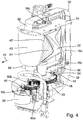
- an LED light module according to the invention is designated in its entirety by the reference symbol 10.
- the LED light module 10 is installed in a housing (not shown) of a motor vehicle headlight and is used to generate a predetermined light distribution which is emitted in a light exit direction 12 in front of the motor vehicle.
- the light distribution can be a low beam, a high beam, a position light, a cornering light and / or any other light function (eg a welcome light).
- the LED light module 10 is particularly compact, can be handled separately as a unit, and can be installed quickly and inexpensively.
- the light module 10 has particularly low tolerances, so that the specified light distribution can be generated with particularly high accuracy.
- the LED light module 10 initially comprises at least one LED 14a, 14b for emitting light.
- the LED light module also includes 10 a holding frame 16 with at least one bearing point 18, 20 and a reflector assembly 22 with a reflector 24 for reflecting at least part of the light emitted by the LEDs 14a, 14b.
- the reflector assembly 22 is mounted in the holding frame 16 so as to be rotatable about a vertical axis of rotation 26 by means of the bearing points 18, 20.
- the LED light module 10 comprises an electrical drive unit 28 for rotating the reflector assembly 22 about the vertical axis of rotation 26.
- the light module 10 comprises an electrical control unit 30 for controlling the drive unit 28 and / or the LEDs 14a, 14b.
- the light module 10 is designed, for example, to implement a welcome light function (can be automatically activated after actuating a door opener of the motor vehicle or after locking the motor vehicle). Further light functions that could be implemented with the light module 10 are, for example, position light, additional low beam and additional high beam (together with another low beam or high beam, produce a low beam or high beam) and cornering light.
- a welcome light function can be automatically activated after actuating a door opener of the motor vehicle or after locking the motor vehicle.
- Further light functions that could be implemented with the light module 10 are, for example, position light, additional low beam and additional high beam (together with another low beam or high beam, produce a low beam or high beam) and cornering light.
- the holding frame 16 is along a vertical sectional plane (in the plane of the drawing Figure 1 or parallel to it), which runs parallel to or congruent with the vertical axis of rotation 26, divided into two frame halves 16a, 16b (cf. Figure 7 ).
- the two bearing points 18, 20 for the reflector assembly are formed to one part 18a, 20a in one frame half 16a and another part 18b, 20b in the other frame half 16b.
- the bearings 18, 20 are thus formed by assembling the two frame halves 16a, 16b.
- the frame halves 16a, 16b are fastened to one another after assembly, for example by means of screws 16c.
- the light source 14b is preferably arranged in a stationary manner on the holding frame 16 and the reflector assembly 22 rotates around the focal point of the light source 14b, that is, the axis of rotation 26 runs through the light source 14b.
- the reflector assembly 22 can rotate by up to +/- 45 ° as required. Even a rotation of the reflector assembly 22 through 360 ° is possible.
- the LEDs 14a, 14b are stationary relative to the holding frame 16 and are arranged in the LED light module 10 in a contactless manner relative to the reflector assembly 22.
- the LEDs 14a, 14b are attached to a circuit board 34 (so-called PCB) and contact is made via it.
- the circuit board 34 is in turn fastened to an underside of an upper section of the holding frame 16.
- the holding frame 16 consists of a material that conducts heat well, in particular a metal, particularly preferably aluminum, so that it serves not only to hold the LEDs 14a, 14b but also as a heat sink for removing heat from the LEDs 14a, 14b.
- the LEDs 14a, 14b are arranged above the reflector assembly 22, so that they emit light with a Lambertian emission characteristic in a downward direction in a 180 ° half-space below the LEDs 14a, 14b Emit in the direction of a reflection surface of the reflector 24.
- the LEDs 14a, 14b are electrically contacted by means of flexible ribbon lines 32, which run at least over part of their longitudinal extent on the outside along the holding frame 16 and are fastened to it.
- the LEDs preferably include an RGB LED 14a for emitting light of any color.
- the RGB-LED 14a can be arranged outside a focal point of the reflector 24 of the reflector assembly 22.
- the RGB-LED 14a is preferably arranged on the circuit board 34 behind the rotating reflector assembly 22 and illuminates an interior area of the headlight.
- colored light can be emitted to implement a welcome light function (can be automatically activated after actuating a door opener of the motor vehicle or after locking the motor vehicle).
- the reflector assembly 22 can rotate about the vertical axis of rotation 26 during the welcome light function, for example by 180 °.
- the LEDs preferably comprise a high-power LED 14b for emitting white light. This is arranged in a focal point of the reflector 24 of the reflector assembly 22. Of course, several high-power LEDs 14b can also be arranged in or near the focal point of the reflector 24. With the aid of such an LED 14b, for example, a low beam function can be implemented. A horizontal (symmetrical or asymmetrical) light-dark boundary of the low beam can be implemented, for example, by a corresponding shape of the reflector 24. Alternatively, it would also be conceivable, at least for the duration of a low beam function, to arrange a diaphragm arrangement (not shown) in the beam path of the light reflected by the reflector 24 in the light exit direction 12.
- An edge of the diaphragm arrangement could then by means of projection optics (not shown) that For example, designed as a projection lens, can be projected as a light-dark boundary onto a roadway in front of the motor vehicle.
- the projection optics could rotate together with the reflector assembly 12.
- the focal point of the reflector 24, in which the high-performance LED 14b is arranged be on the vertical axis of rotation 26 of the reflector assembly 22 lies.
- the reflector assembly 22 has a light disk 40 in the beam path of the light reflected by the reflector 24, through which the reflected light passes and into which light can be coupled via at least one of its side surfaces, which is at least partially in the direction of the reflector 24 reflected and in the light exit direction 12 passing through the lens 40 exits the lens 40 so that it appears as a luminous surface.
- a position light can be implemented by the light emerging from the lens 40.
- the light disk 40 is assigned a light guide 42 which surrounds the light disk 40 on the circumferential side at least around several of its side surfaces.
- Light can be coupled into the end faces of the light guide 42, which at least partially emerges from the light guide 42 in the direction of the side faces of the light disk 40 and couples into the light disk 40 via the side faces.
- the light coupled into the light guide 42 is preferably generated by one or more LEDs 14c. These can be arranged on the same circuit board 34 as the other LEDs 14a, 14b. The light emitted by the LEDs 14c therefore only hits the end faces of the light guide 42 when the reflector assembly 22 is in its starting position, in which it is directed straight ahead in the direction of travel and not rotated about the axis of rotation 26.
- the holding frame 16 preferably has lateral bearing points 36 (cf. Figure 7 ), by means of which the entire LED light module 10 can be pivoted about a horizontal axis of rotation 38.
- a headlight range control can be implemented by vertically pivoting the reflector assembly 10 about the horizontal axis of rotation 38.
- a light function for example an 'additional high beam'
- the high beam would consist of a raised low beam.
- the LED light module 10 has a gear.
- the drive unit 28 is designed as an electric motor, particularly preferably as a stepping motor, and the gear 44 is fastened in a rotationally fixed manner on a motor shaft 46 of the motor 28.
- the reflector assembly 22 is assigned a further gear 48 of the transmission.
- the gear is designed as a tensioned gear to minimize / avoid backlash.
- the two frame halves 16a, 16b have depressions 50a, 50b in which, after assembly of the two frame halves 16a, 16b, the gears 44, 48 are added.
- the reflector assembly 22 is assigned at least one magnet 52 and the drive unit 28 or the holding frame 16 is assigned a magnetic field-sensitive sensor 54, the two frame halves 16a, 16b having recesses 50c in which, after the two frame halves 16a, 16b have been assembled, the magnet 52 and the sensor 54 are included (cf. Figures 7 and 8th ).
- the sensor 54 is arranged on a circuit board 56, for example.
- the sensor 54 is preferably designed as a Hall sensor.
- the magnet 52 is preferably designed as a ring magnet which is an integral part of the further gearwheel 48 or which forms at least one unit with it. Thus, the magnet 52 is also received in the recesses 50b of the frame halves 16a, 16b, in which the further gearwheel 48 is also received.
- the drive unit 28 is preferably fastened on the outside of the holding frame 16.
- the holding frame 16 has an opening 58 for a movable actuating element of the drive unit 28, in particular for the motor shaft 46 of an electric motor.
- One part 58a of the opening 58 is in one frame half 16a and another part (in Figure 7 not visible) in the other frame half 16b.
- the opening 58 is thus formed by assembling the two frame halves 16a, 16b.
- the drive of the further gearwheel 48 of the transmission assigned to the reflector assembly 22 can take place directly through the first gearwheel 44, or else indirectly via at least one further gearwheel.
- the transmission has two further gears 60a, 60b (cf. Figure 5 ).
- the corresponding bearing points 62, 64 are formed to one part 62a, 64a in one frame half 16a and to another part (not shown) in the other frame half 16b and the bearing points 62, 64 are formed by assembling the form two frame halves 16a, 16b.
- control unit 30 be fastened on the outside of the holding frame 16.
- the control unit 30 comprises, for example, a printed circuit board (so-called PCB) on which electrical and electronic components, sockets, plugs, contact pins, etc. can be arranged and contacted.
- the control unit 30 is preferably screwed to the outside of the holding frame 16. In the illustrated example, the control unit 30 is attached to an underside of a lower section of the holding frame 16.
- a light module group 100 is shown in each case, which comprises a plurality of LED light modules 10 arranged next to one another from the Figures 1 to 8 having.
- the light module group 100 comprises three light modules 10 arranged next to one another.
- the light module group 100 comprises a carrier element 102 which is permanently connected to a housing of the headlight in which the light module group 100 is installed and which has recesses 104 for receiving the three LED light modules 10 .
- the light modules 10 are each mounted pivotably about a horizontal axis of rotation 38 via their respective lateral bearing points 36 on the carrier element 102.
- the horizontal axes 38 do not have to be congruent. Nor do they all have to be on the same horizontal plane. In the example, the axes 38 are arranged on different horizontal planes (cf. Figure 10 ) and run backwards (in the drawing plane of the Figure 9 ) offset to each other.
- the three light modules 10 are pivoted together by the same amount.
- a common distribution linkage 106 is articulated to the top of each LED light module 10 or to an upper section of the holding frame 16.
- the distributor linkage 106 is moved parallel to the light exit direction 12 by means of an actuator (not shown), which is designed, for example, as an electric motor, preferably as a stepper motor, or as a magnet. This movement of the linkage 106 leads to a vertical pivoting of the light modules 10.
- an actuator not shown
Landscapes
- Engineering & Computer Science (AREA)
- General Engineering & Computer Science (AREA)
- Physics & Mathematics (AREA)
- Microelectronics & Electronic Packaging (AREA)
- Optics & Photonics (AREA)
- Non-Portable Lighting Devices Or Systems Thereof (AREA)
- Lighting Device Outwards From Vehicle And Optical Signal (AREA)
Claims (15)
- Module de lumière à DEL (10) pour un phare de véhicule automobile, ledit module de lumière (10) comprenant au moins une DEL (14a, 14b, 14c) pour émettre de la lumière, un ensemble de réflecteur (22) qui est supporté à rotation, au moyen d'au moins un point de support (18, 20), autour d'un axe vertical de rotation (26) dans un cadre de maintien (16) et qui comprend un réflecteur (24) pour réfléchir au moins une partie de la lumière émise, une unité d'entraînement électrique (28) pour faire tourner ledit ensemble de réflecteur (22) autour de l'axe vertical de rotation (26), et une unité de commande électrique (30) pour commander l'unité d'entraînement (28), caractérisé par le fait que le cadre de maintien (16) est divisé en deux moitiés de cadre (16a, 16b) le long d'un plan de coupe vertical qui s'étend parallèlement à ou coïncide avec l'axe vertical de rotation (26), dans lequel ledit au moins un point de support (18, 20) pour l'ensemble de réflecteur (22) est réalisé pour une partie (18a, 20a) dans l'une (16a) des moitiés de cadre et pour une autre partie (18b, 20b) dans l'autre moitié de cadre (16b), et ledit au moins un point de support (18, 20) est formé en assemblant les deux moitiés de cadre (16a, 16b).
- Module de lumière à DEL (10) selon la revendication 1, caractérisé par le fait que l'ensemble de réflecteur (22) est supporté à rotation au moyen de deux points de support (18, 20) autour de l'axe vertical de rotation (26) dans le cadre de maintien (16), dans lequel les deux points de support (18, 20) sont disposés au-dessous de l'ensemble de réflecteur (22) sur une portion inférieure du cadre de maintien (16) en étant décalés l'un par rapport à l'autre le long de l'axe vertical de rotation (26) .
- Module de lumière à DEL (10) selon la revendication 1 ou 2, caractérisé par le fait qu'à l'unité d'entraînement (28) est associée au moins une roue dentée (44) d'un engrenage qui est prévu pour transformer un mouvement d'actionnement de l'unité d'entraînement (28) en un mouvement de rotation correspondant de l'ensemble de réflecteur (22) autour de l'axe vertical de rotation (26), et qu'à l'ensemble de réflecteur (22) est associée au moins une autre roue dentée (48) de l'engrenage, dans lequel les deux moitiés de cadre (16a, 16b) comprennent des creux (50a, 50b) dans lesquels sont logées les roues dentées (44, 48) après avoir assemblé les deux moitiés de cadre (16a, 16b).
- Module de lumière à DEL (10) selon l'une quelconque des revendications 1 à 3, caractérisé par le fait qu'à l'ensemble de réflecteur (22) est associé au moins un aimant (54) et qu'à l'unité d'entraînement (28) est associé un capteur (54) sensible aux champs magnétiques, dans lequel les deux moitiés de cadre (16a, 16b) présentent des creux (50b, 50c) dans lesquels sont logés l'aimant (54) et le capteur (56) après avoir assemblé les deux moitiés de cadre (16a, 16b).
- Module de lumière à DEL (10) selon l'une quelconque des revendications 1 à 3, caractérisé par le fait qu'à l'ensemble de réflecteur (22) est associé au moins un aimant (54) et qu'à l'unité d'entraînement (28) est associé un capteur (54) sensible aux champs magnétiques, dans lequel les deux moitiés de cadre (16a, 16b) présentent des creux (50b, 50c) dans lesquels sont logés l'aimant (54) et le capteur (56) après avoir assemblé les deux moitiés de cadre (16a, 16b).
- Module de lumière à DEL (10) selon l'une quelconque des revendications 1 à 5, caractérisé par le fait que l'unité de commande (30) est fixée à l'extérieur du cadre de maintien (16).
- Module de lumière à DEL (10) selon l'une quelconque des revendications 1 à 6, caractérisé par le fait que ladite au moins une DEL (14a, 14b, 14c) est disposé dans le module de lumière (10) de manière fixe par rapport au cadre de maintien (16) et sans contact par rapport à l'ensemble de réflecteur (22).
- Module de lumière à DEL (10) selon la revendication 7, caractérisé par le fait que ladite au moins une DEL (14a, 14b, 14c) est disposée au-dessus de l'ensemble de réflecteur (22) lorsque le module de lumière (10) est monté dans le phare de véhicule automobile.
- Module de lumière à DEL (10) selon la revendication 7 ou 8, caractérisé par le fait que ladite au moins une DEL (14a, 14b, 14c) est mise en contact électrique au moyen de lignes de ruban souple (32) qui s'étendent le long de l'extérieur du cadre de maintien (16).
- Module de lumière à DEL (10) selon l'une quelconque des revendications 1 à 9, caractérisé par le fait que ladite au moins une DEL comprend une DEL RVB (14a) pour émettre de la lumière de n'importe quelle couleur.
- Module de lumière à DEL (10) selon l'une quelconque des revendications 1 à 10, caractérisé par le fait que ladite au moins une DEL comprend une DEL à haute puissance (14b) destinée à émettre de la lumière blanche et qui est disposée dans un foyer du réflecteur (24).
- Module de lumière à DEL (10) selon la revendication 11, caractérisé par le fait que le foyer du réflecteur (24) se situe sur l'axe vertical de rotation (26).
- Module de lumière à DEL (10) selon l'une quelconque des revendications 1 à 12, caractérisé par le fait que le cadre de maintien (16) présente des points de support latéraux (36) au moyen desquels le module de lumière à DEL (10) peut pivoter autour d'un plan horizontal de rotation (38).
- Module de lumière à DEL (10) selon l'une quelconque des revendications 1 à 13, caractérisé par le fait que l'ensemble de réflecteur (22) comprend une glace (40) dans le trajet des rayons de la lumière réfléchie par le réflecteur (24), laquelle est traversée par la lumière réfléchie et dans laquelle peut être couplée de la lumière via au moins une de ses faces latérales, qui sort au moins en partie dans la direction (12) de la lumière réfléchie par le réflecteur (24) et traversant la glace (40) de sorte que celle-ci apparaît comme une surface lumineuse.
- Module de lumière à DEL (10) selon la revendication 14, caractérisé par le fait que la glace (40) présente un guide de lumière (42) au moins autour de plusieurs de ses faces latérales, dans lequel peut être couplée de la lumière qui sort du guide de lumière (42) au moins en partie dans la direction des faces latérales de la glace (40) et est couplée dans la glace (40) via les faces latérales.
Applications Claiming Priority (2)
| Application Number | Priority Date | Filing Date | Title |
|---|---|---|---|
| DE102017111447.5A DE102017111447A1 (de) | 2017-05-24 | 2017-05-24 | LED-Lichtmodul für einen Kraftfahrzeugscheinwerfer |
| PCT/EP2018/062541 WO2018215244A1 (fr) | 2017-05-24 | 2018-05-15 | Module d'éclairage à del pour un phare de véhicule à moteur |
Publications (2)
| Publication Number | Publication Date |
|---|---|
| EP3631288A1 EP3631288A1 (fr) | 2020-04-08 |
| EP3631288B1 true EP3631288B1 (fr) | 2021-07-28 |
Family
ID=62235932
Family Applications (1)
| Application Number | Title | Priority Date | Filing Date |
|---|---|---|---|
| EP18726755.4A Active EP3631288B1 (fr) | 2017-05-24 | 2018-05-15 | Module d'éclairage à del pour un phare de véhicule à moteur |
Country Status (4)
| Country | Link |
|---|---|
| EP (1) | EP3631288B1 (fr) |
| CN (1) | CN110945281B (fr) |
| DE (1) | DE102017111447A1 (fr) |
| WO (1) | WO2018215244A1 (fr) |
Families Citing this family (2)
| Publication number | Priority date | Publication date | Assignee | Title |
|---|---|---|---|---|
| CN114234121B (zh) * | 2021-12-21 | 2024-04-19 | 佛山市新中颖光电科技有限公司 | 一种可进行照明范围调节的激光led车灯 |
| DE102023212228A1 (de) * | 2023-12-05 | 2025-06-05 | Stellantis Auto Sas | Nahfeldprojektionseinrichtung mit schwenkbarem Spiegel für ein Kraftfahrzeug |
Family Cites Families (23)
| Publication number | Priority date | Publication date | Assignee | Title |
|---|---|---|---|---|
| FR2765562B1 (fr) | 1997-07-07 | 1999-09-24 | Valeo Vision | Boitier etanche en au moins deux parties, et correcteur d'orientation de faisceau l'incorporant pour projecteur de vehicule automobile |
| DE102006022403A1 (de) * | 2006-05-13 | 2007-11-22 | Hella Kgaa Hueck & Co. | Scheinwerfer für Fahrzeuge und Montageverfahren |
| DE102007008646B4 (de) * | 2007-02-20 | 2012-09-20 | Automotive Lighting Reutlingen Gmbh | Beleuchtungseinrichtung für ein Kraftfahrzeug |
| JP2008257959A (ja) * | 2007-04-03 | 2008-10-23 | Koito Mfg Co Ltd | 車両用灯具 |
| JP4492637B2 (ja) * | 2007-04-25 | 2010-06-30 | 市光工業株式会社 | 車両用前照灯 |
| FR2919547B1 (fr) * | 2007-08-03 | 2010-01-08 | Valeo Vision | Dispositif de montage d'un module optique dans un projecteur pour vehicule automobile |
| DE102007053727B4 (de) * | 2007-11-10 | 2019-07-11 | Automotive Lighting Reutlingen Gmbh | Kraftfahrzeugscheinwerfer mit federnd gelagertem Lichtmodul |
| DE202008005444U1 (de) | 2008-04-18 | 2008-08-07 | Automotive Lighting Reutlingen Gmbh | Scheinwerfer für ein Kraftfahrzeug |
| JP5281356B2 (ja) * | 2008-10-14 | 2013-09-04 | 株式会社小糸製作所 | 前照灯ユニット |
| JP5346554B2 (ja) | 2008-10-31 | 2013-11-20 | 株式会社小糸製作所 | 車輌用前照灯 |
| CN201348208Y (zh) * | 2009-01-06 | 2009-11-18 | 韩国可莱特株式会社 | 一种带有方向性镜片的指示灯 |
| DE102009031410A1 (de) * | 2009-07-02 | 2011-01-05 | Automotive Lighting Reutlingen Gmbh | Beleuchtungseinrichtung für ein Kraftfahrzeug |
| CN103109131B (zh) | 2010-07-26 | 2016-03-09 | 法雷奥照明公司 | 用于机动车辆的照明和/或信号装置的光学模块 |
| DE102010045435B4 (de) * | 2010-09-15 | 2019-10-10 | HELLA GmbH & Co. KGaA | Projektionsscheinwerfer für Fahrzeuge |
| DE102011003908B4 (de) * | 2011-02-10 | 2019-04-18 | Automotive Lighting Reutlingen Gmbh | Scheinwerfer eines Kraftfahrzeugs |
| DE102011003910B4 (de) * | 2011-02-10 | 2016-02-18 | Automotive Lighting Reutlingen Gmbh | Scheinwerfer eines Kraftfahrzeugs |
| JP5666977B2 (ja) * | 2011-04-26 | 2015-02-12 | 株式会社小糸製作所 | 車両用灯具 |
| AT513123B1 (de) * | 2012-07-11 | 2023-11-15 | Zkw Group Gmbh | Beleuchtungsvorrichtung für ein Kraftfahrzeug, Scheinwerfer sowie Scheinwerfersystem |
| FR3022868B1 (fr) * | 2014-06-30 | 2018-01-12 | Valeo Vision | Montage pivotant d'un module d'eclairage pour vehicule autombile |
| CN104266147A (zh) * | 2014-09-28 | 2015-01-07 | 江苏申通汽车零部件有限公司 | 一种汽车灯具用反光镜调节机构 |
| EP3176493B1 (fr) * | 2015-11-24 | 2020-12-30 | Marelli Automotive Lighting Italy S.p.A. | Module d'éclairage rotatif et dispositif d'éclairage pour véhicule |
| CN105387410A (zh) | 2015-11-24 | 2016-03-09 | 马瑞利汽车零部件(芜湖)有限公司 | 汽车车灯afs调光模组 |
| CN206145553U (zh) * | 2016-09-22 | 2017-05-03 | 常州星宇车灯股份有限公司 | 车用前照灯远近光调光装置 |
-
2017
- 2017-05-24 DE DE102017111447.5A patent/DE102017111447A1/de not_active Ceased
-
2018
- 2018-05-15 CN CN201880033658.9A patent/CN110945281B/zh active Active
- 2018-05-15 WO PCT/EP2018/062541 patent/WO2018215244A1/fr not_active Ceased
- 2018-05-15 EP EP18726755.4A patent/EP3631288B1/fr active Active
Also Published As
| Publication number | Publication date |
|---|---|
| EP3631288A1 (fr) | 2020-04-08 |
| CN110945281B (zh) | 2022-03-15 |
| WO2018215244A1 (fr) | 2018-11-29 |
| CN110945281A (zh) | 2020-03-31 |
| DE102017111447A1 (de) | 2018-11-29 |
Similar Documents
| Publication | Publication Date | Title |
|---|---|---|
| DE102004061873B4 (de) | Fahrzeugbeleuchtungsvorrichtung | |
| EP2042801B1 (fr) | Source lumineuse dotée de caractéristiques d'émission modifiables | |
| DE102007021865B4 (de) | Beleuchtungseinrichtung für ein Fahrzeug | |
| EP2314912B1 (fr) | Lampe à DEL dotée d'un angle de rayonnement réglable en continu | |
| DE102010063713A1 (de) | Beleuchtungsvorrichtung | |
| EP1627267B1 (fr) | Bouton tournant pour dispositif de commande | |
| DE102014214236B4 (de) | Beleuchtungseinrichtung mit einem Justiermechanismus und einer vorstehenden Rippe | |
| DE102014200237B4 (de) | Scheinwerfer eines Kraftfahrzeugs | |
| DE102016117423B4 (de) | Scheinwerferbaugruppe mit drehender Einfassung | |
| EP3631288B1 (fr) | Module d'éclairage à del pour un phare de véhicule à moteur | |
| EP2088364A1 (fr) | Phares de projection pour véhicules | |
| DE102009054101A1 (de) | Beleuchtungsvorrichtung für ein Fahrzeug | |
| WO2008119483A2 (fr) | Élément de commande pour véhicule à moteur | |
| DE10315251A1 (de) | Flache Leuchtvorrichtung | |
| EP2848860B1 (fr) | Module d'éclairage pour un dispositif d'éclairage et dispositif d'éclairage doté d'un tel module d'éclairage | |
| EP3446033B1 (fr) | Éclairage d'armoire de distribution pour éclairer l'espace intérieur d'une armoire de distribution | |
| DE3533056A1 (de) | Mehrstufiger, beleuchteter schalter an kraftfahrzeugen | |
| DE102008055694A1 (de) | Stellrad | |
| DE20004188U1 (de) | Leuchte | |
| DE1622845A1 (de) | Nebelleuchte | |
| EP3443188B1 (fr) | Serrure de véhicule automobile | |
| EP3880548B1 (fr) | Phare pour une motocyclette | |
| DE102008011170B4 (de) | Scheinwerfer, insbesondere Kraftfahrzeugscheinwerfer | |
| DE102007050348A1 (de) | Beleuchtungseinrichtung für ein Kraftfahrzeug | |
| EP2959222B1 (fr) | Lumière sous-marine et système de sécurité |
Legal Events
| Date | Code | Title | Description |
|---|---|---|---|
| STAA | Information on the status of an ep patent application or granted ep patent |
Free format text: STATUS: UNKNOWN |
|
| STAA | Information on the status of an ep patent application or granted ep patent |
Free format text: STATUS: THE INTERNATIONAL PUBLICATION HAS BEEN MADE |
|
| PUAI | Public reference made under article 153(3) epc to a published international application that has entered the european phase |
Free format text: ORIGINAL CODE: 0009012 |
|
| STAA | Information on the status of an ep patent application or granted ep patent |
Free format text: STATUS: REQUEST FOR EXAMINATION WAS MADE |
|
| 17P | Request for examination filed |
Effective date: 20191220 |
|
| AK | Designated contracting states |
Kind code of ref document: A1 Designated state(s): AL AT BE BG CH CY CZ DE DK EE ES FI FR GB GR HR HU IE IS IT LI LT LU LV MC MK MT NL NO PL PT RO RS SE SI SK SM TR |
|
| AX | Request for extension of the european patent |
Extension state: BA ME |
|
| DAV | Request for validation of the european patent (deleted) | ||
| DAX | Request for extension of the european patent (deleted) | ||
| GRAP | Despatch of communication of intention to grant a patent |
Free format text: ORIGINAL CODE: EPIDOSNIGR1 |
|
| STAA | Information on the status of an ep patent application or granted ep patent |
Free format text: STATUS: GRANT OF PATENT IS INTENDED |
|
| INTG | Intention to grant announced |
Effective date: 20210219 |
|
| GRAS | Grant fee paid |
Free format text: ORIGINAL CODE: EPIDOSNIGR3 |
|
| GRAA | (expected) grant |
Free format text: ORIGINAL CODE: 0009210 |
|
| STAA | Information on the status of an ep patent application or granted ep patent |
Free format text: STATUS: THE PATENT HAS BEEN GRANTED |
|
| AK | Designated contracting states |
Kind code of ref document: B1 Designated state(s): AL AT BE BG CH CY CZ DE DK EE ES FI FR GB GR HR HU IE IS IT LI LT LU LV MC MK MT NL NO PL PT RO RS SE SI SK SM TR |
|
| REG | Reference to a national code |
Ref country code: GB Ref legal event code: FG4D Free format text: NOT ENGLISH |
|
| REG | Reference to a national code |
Ref country code: CH Ref legal event code: EP |
|
| REG | Reference to a national code |
Ref country code: AT Ref legal event code: REF Ref document number: 1415024 Country of ref document: AT Kind code of ref document: T Effective date: 20210815 |
|
| REG | Reference to a national code |
Ref country code: IE Ref legal event code: FG4D Free format text: LANGUAGE OF EP DOCUMENT: GERMAN |
|
| REG | Reference to a national code |
Ref country code: DE Ref legal event code: R096 Ref document number: 502018006328 Country of ref document: DE |
|
| REG | Reference to a national code |
Ref country code: LT Ref legal event code: MG9D |
|
| REG | Reference to a national code |
Ref country code: NL Ref legal event code: MP Effective date: 20210728 |
|
| PG25 | Lapsed in a contracting state [announced via postgrant information from national office to epo] |
Ref country code: LT Free format text: LAPSE BECAUSE OF FAILURE TO SUBMIT A TRANSLATION OF THE DESCRIPTION OR TO PAY THE FEE WITHIN THE PRESCRIBED TIME-LIMIT Effective date: 20210728 Ref country code: BG Free format text: LAPSE BECAUSE OF FAILURE TO SUBMIT A TRANSLATION OF THE DESCRIPTION OR TO PAY THE FEE WITHIN THE PRESCRIBED TIME-LIMIT Effective date: 20211028 Ref country code: NO Free format text: LAPSE BECAUSE OF FAILURE TO SUBMIT A TRANSLATION OF THE DESCRIPTION OR TO PAY THE FEE WITHIN THE PRESCRIBED TIME-LIMIT Effective date: 20211028 Ref country code: PT Free format text: LAPSE BECAUSE OF FAILURE TO SUBMIT A TRANSLATION OF THE DESCRIPTION OR TO PAY THE FEE WITHIN THE PRESCRIBED TIME-LIMIT Effective date: 20211129 Ref country code: NL Free format text: LAPSE BECAUSE OF FAILURE TO SUBMIT A TRANSLATION OF THE DESCRIPTION OR TO PAY THE FEE WITHIN THE PRESCRIBED TIME-LIMIT Effective date: 20210728 Ref country code: FI Free format text: LAPSE BECAUSE OF FAILURE TO SUBMIT A TRANSLATION OF THE DESCRIPTION OR TO PAY THE FEE WITHIN THE PRESCRIBED TIME-LIMIT Effective date: 20210728 Ref country code: ES Free format text: LAPSE BECAUSE OF FAILURE TO SUBMIT A TRANSLATION OF THE DESCRIPTION OR TO PAY THE FEE WITHIN THE PRESCRIBED TIME-LIMIT Effective date: 20210728 Ref country code: HR Free format text: LAPSE BECAUSE OF FAILURE TO SUBMIT A TRANSLATION OF THE DESCRIPTION OR TO PAY THE FEE WITHIN THE PRESCRIBED TIME-LIMIT Effective date: 20210728 Ref country code: RS Free format text: LAPSE BECAUSE OF FAILURE TO SUBMIT A TRANSLATION OF THE DESCRIPTION OR TO PAY THE FEE WITHIN THE PRESCRIBED TIME-LIMIT Effective date: 20210728 Ref country code: SE Free format text: LAPSE BECAUSE OF FAILURE TO SUBMIT A TRANSLATION OF THE DESCRIPTION OR TO PAY THE FEE WITHIN THE PRESCRIBED TIME-LIMIT Effective date: 20210728 |
|
| PG25 | Lapsed in a contracting state [announced via postgrant information from national office to epo] |
Ref country code: PL Free format text: LAPSE BECAUSE OF FAILURE TO SUBMIT A TRANSLATION OF THE DESCRIPTION OR TO PAY THE FEE WITHIN THE PRESCRIBED TIME-LIMIT Effective date: 20210728 Ref country code: LV Free format text: LAPSE BECAUSE OF FAILURE TO SUBMIT A TRANSLATION OF THE DESCRIPTION OR TO PAY THE FEE WITHIN THE PRESCRIBED TIME-LIMIT Effective date: 20210728 Ref country code: GR Free format text: LAPSE BECAUSE OF FAILURE TO SUBMIT A TRANSLATION OF THE DESCRIPTION OR TO PAY THE FEE WITHIN THE PRESCRIBED TIME-LIMIT Effective date: 20211029 |
|
| PG25 | Lapsed in a contracting state [announced via postgrant information from national office to epo] |
Ref country code: DK Free format text: LAPSE BECAUSE OF FAILURE TO SUBMIT A TRANSLATION OF THE DESCRIPTION OR TO PAY THE FEE WITHIN THE PRESCRIBED TIME-LIMIT Effective date: 20210728 |
|
| REG | Reference to a national code |
Ref country code: DE Ref legal event code: R097 Ref document number: 502018006328 Country of ref document: DE |
|
| PG25 | Lapsed in a contracting state [announced via postgrant information from national office to epo] |
Ref country code: SM Free format text: LAPSE BECAUSE OF FAILURE TO SUBMIT A TRANSLATION OF THE DESCRIPTION OR TO PAY THE FEE WITHIN THE PRESCRIBED TIME-LIMIT Effective date: 20210728 Ref country code: SK Free format text: LAPSE BECAUSE OF FAILURE TO SUBMIT A TRANSLATION OF THE DESCRIPTION OR TO PAY THE FEE WITHIN THE PRESCRIBED TIME-LIMIT Effective date: 20210728 Ref country code: RO Free format text: LAPSE BECAUSE OF FAILURE TO SUBMIT A TRANSLATION OF THE DESCRIPTION OR TO PAY THE FEE WITHIN THE PRESCRIBED TIME-LIMIT Effective date: 20210728 Ref country code: EE Free format text: LAPSE BECAUSE OF FAILURE TO SUBMIT A TRANSLATION OF THE DESCRIPTION OR TO PAY THE FEE WITHIN THE PRESCRIBED TIME-LIMIT Effective date: 20210728 Ref country code: CZ Free format text: LAPSE BECAUSE OF FAILURE TO SUBMIT A TRANSLATION OF THE DESCRIPTION OR TO PAY THE FEE WITHIN THE PRESCRIBED TIME-LIMIT Effective date: 20210728 Ref country code: AL Free format text: LAPSE BECAUSE OF FAILURE TO SUBMIT A TRANSLATION OF THE DESCRIPTION OR TO PAY THE FEE WITHIN THE PRESCRIBED TIME-LIMIT Effective date: 20210728 |
|
| PLBE | No opposition filed within time limit |
Free format text: ORIGINAL CODE: 0009261 |
|
| STAA | Information on the status of an ep patent application or granted ep patent |
Free format text: STATUS: NO OPPOSITION FILED WITHIN TIME LIMIT |
|
| 26N | No opposition filed |
Effective date: 20220429 |
|
| PG25 | Lapsed in a contracting state [announced via postgrant information from national office to epo] |
Ref country code: IT Free format text: LAPSE BECAUSE OF FAILURE TO SUBMIT A TRANSLATION OF THE DESCRIPTION OR TO PAY THE FEE WITHIN THE PRESCRIBED TIME-LIMIT Effective date: 20210728 |
|
| REG | Reference to a national code |
Ref country code: CH Ref legal event code: PL |
|
| REG | Reference to a national code |
Ref country code: BE Ref legal event code: MM Effective date: 20220531 |
|
| GBPC | Gb: european patent ceased through non-payment of renewal fee |
Effective date: 20220515 |
|
| PG25 | Lapsed in a contracting state [announced via postgrant information from national office to epo] |
Ref country code: MC Free format text: LAPSE BECAUSE OF FAILURE TO SUBMIT A TRANSLATION OF THE DESCRIPTION OR TO PAY THE FEE WITHIN THE PRESCRIBED TIME-LIMIT Effective date: 20210728 Ref country code: LU Free format text: LAPSE BECAUSE OF NON-PAYMENT OF DUE FEES Effective date: 20220515 Ref country code: LI Free format text: LAPSE BECAUSE OF NON-PAYMENT OF DUE FEES Effective date: 20220531 Ref country code: CH Free format text: LAPSE BECAUSE OF NON-PAYMENT OF DUE FEES Effective date: 20220531 |
|
| PG25 | Lapsed in a contracting state [announced via postgrant information from national office to epo] |
Ref country code: IE Free format text: LAPSE BECAUSE OF NON-PAYMENT OF DUE FEES Effective date: 20220515 Ref country code: FR Free format text: LAPSE BECAUSE OF NON-PAYMENT OF DUE FEES Effective date: 20220531 |
|
| PG25 | Lapsed in a contracting state [announced via postgrant information from national office to epo] |
Ref country code: GB Free format text: LAPSE BECAUSE OF NON-PAYMENT OF DUE FEES Effective date: 20220515 Ref country code: BE Free format text: LAPSE BECAUSE OF NON-PAYMENT OF DUE FEES Effective date: 20220531 |
|
| PG25 | Lapsed in a contracting state [announced via postgrant information from national office to epo] |
Ref country code: MK Free format text: LAPSE BECAUSE OF FAILURE TO SUBMIT A TRANSLATION OF THE DESCRIPTION OR TO PAY THE FEE WITHIN THE PRESCRIBED TIME-LIMIT Effective date: 20210728 Ref country code: CY Free format text: LAPSE BECAUSE OF FAILURE TO SUBMIT A TRANSLATION OF THE DESCRIPTION OR TO PAY THE FEE WITHIN THE PRESCRIBED TIME-LIMIT Effective date: 20210728 |
|
| PG25 | Lapsed in a contracting state [announced via postgrant information from national office to epo] |
Ref country code: HU Free format text: LAPSE BECAUSE OF FAILURE TO SUBMIT A TRANSLATION OF THE DESCRIPTION OR TO PAY THE FEE WITHIN THE PRESCRIBED TIME-LIMIT; INVALID AB INITIO Effective date: 20180515 |
|
| PG25 | Lapsed in a contracting state [announced via postgrant information from national office to epo] |
Ref country code: TR Free format text: LAPSE BECAUSE OF FAILURE TO SUBMIT A TRANSLATION OF THE DESCRIPTION OR TO PAY THE FEE WITHIN THE PRESCRIBED TIME-LIMIT Effective date: 20210728 |
|
| REG | Reference to a national code |
Ref country code: AT Ref legal event code: MM01 Ref document number: 1415024 Country of ref document: AT Kind code of ref document: T Effective date: 20230515 |
|
| PG25 | Lapsed in a contracting state [announced via postgrant information from national office to epo] |
Ref country code: AT Free format text: LAPSE BECAUSE OF NON-PAYMENT OF DUE FEES Effective date: 20230515 |
|
| PG25 | Lapsed in a contracting state [announced via postgrant information from national office to epo] |
Ref country code: AT Free format text: LAPSE BECAUSE OF NON-PAYMENT OF DUE FEES Effective date: 20230515 |
|
| PG25 | Lapsed in a contracting state [announced via postgrant information from national office to epo] |
Ref country code: MT Free format text: LAPSE BECAUSE OF FAILURE TO SUBMIT A TRANSLATION OF THE DESCRIPTION OR TO PAY THE FEE WITHIN THE PRESCRIBED TIME-LIMIT Effective date: 20210728 |
|
| PGFP | Annual fee paid to national office [announced via postgrant information from national office to epo] |
Ref country code: DE Payment date: 20250423 Year of fee payment: 8 |
|
| REG | Reference to a national code |
Ref country code: DE Ref legal event code: R081 Ref document number: 502018006328 Country of ref document: DE Owner name: MARELLI GERMANY GMBH, DE Free format text: FORMER OWNER: AUTOMOTIVE LIGHTING REUTLINGEN GMBH, 72762 REUTLINGEN, DE |
|
| PGFP | Annual fee paid to national office [announced via postgrant information from national office to epo] |
Ref country code: AT Payment date: 20260410 Year of fee payment: 5 |