EP3880548B1 - Phare pour une motocyclette - Google Patents
Phare pour une motocyclette Download PDFInfo
- Publication number
- EP3880548B1 EP3880548B1 EP19794978.7A EP19794978A EP3880548B1 EP 3880548 B1 EP3880548 B1 EP 3880548B1 EP 19794978 A EP19794978 A EP 19794978A EP 3880548 B1 EP3880548 B1 EP 3880548B1
- Authority
- EP
- European Patent Office
- Prior art keywords
- motorcycle
- lighting unit
- light
- headlight according
- headlight
- Prior art date
- Legal status (The legal status is an assumption and is not a legal conclusion. Google has not performed a legal analysis and makes no representation as to the accuracy of the status listed.)
- Active
Links
Images


Classifications
-
- B—PERFORMING OPERATIONS; TRANSPORTING
- B60—VEHICLES IN GENERAL
- B60Q—ARRANGEMENT OF SIGNALLING OR LIGHTING DEVICES, THE MOUNTING OR SUPPORTING THEREOF OR CIRCUITS THEREFOR, FOR VEHICLES IN GENERAL
- B60Q1/00—Arrangement of optical signalling or lighting devices, the mounting or supporting thereof or circuits therefor
- B60Q1/02—Arrangement of optical signalling or lighting devices, the mounting or supporting thereof or circuits therefor the devices being primarily intended to illuminate the way ahead or to illuminate other areas of way or environments
- B60Q1/04—Arrangement of optical signalling or lighting devices, the mounting or supporting thereof or circuits therefor the devices being primarily intended to illuminate the way ahead or to illuminate other areas of way or environments the devices being headlights
- B60Q1/06—Arrangement of optical signalling or lighting devices, the mounting or supporting thereof or circuits therefor the devices being primarily intended to illuminate the way ahead or to illuminate other areas of way or environments the devices being headlights adjustable, e.g. remotely-controlled from inside vehicle
- B60Q1/076—Arrangement of optical signalling or lighting devices, the mounting or supporting thereof or circuits therefor the devices being primarily intended to illuminate the way ahead or to illuminate other areas of way or environments the devices being headlights adjustable, e.g. remotely-controlled from inside vehicle by electrical means including means to transmit the movements, e.g. shafts or joints
-
- B—PERFORMING OPERATIONS; TRANSPORTING
- B60—VEHICLES IN GENERAL
- B60Q—ARRANGEMENT OF SIGNALLING OR LIGHTING DEVICES, THE MOUNTING OR SUPPORTING THEREOF OR CIRCUITS THEREFOR, FOR VEHICLES IN GENERAL
- B60Q1/00—Arrangement of optical signalling or lighting devices, the mounting or supporting thereof or circuits therefor
- B60Q1/0029—Spatial arrangement
- B60Q1/0041—Spatial arrangement of several lamps in relation to each other
-
- B—PERFORMING OPERATIONS; TRANSPORTING
- B60—VEHICLES IN GENERAL
- B60Q—ARRANGEMENT OF SIGNALLING OR LIGHTING DEVICES, THE MOUNTING OR SUPPORTING THEREOF OR CIRCUITS THEREFOR, FOR VEHICLES IN GENERAL
- B60Q1/00—Arrangement of optical signalling or lighting devices, the mounting or supporting thereof or circuits therefor
- B60Q1/02—Arrangement of optical signalling or lighting devices, the mounting or supporting thereof or circuits therefor the devices being primarily intended to illuminate the way ahead or to illuminate other areas of way or environments
- B60Q1/04—Arrangement of optical signalling or lighting devices, the mounting or supporting thereof or circuits therefor the devices being primarily intended to illuminate the way ahead or to illuminate other areas of way or environments the devices being headlights
- B60Q1/06—Arrangement of optical signalling or lighting devices, the mounting or supporting thereof or circuits therefor the devices being primarily intended to illuminate the way ahead or to illuminate other areas of way or environments the devices being headlights adjustable, e.g. remotely-controlled from inside vehicle
- B60Q1/08—Arrangement of optical signalling or lighting devices, the mounting or supporting thereof or circuits therefor the devices being primarily intended to illuminate the way ahead or to illuminate other areas of way or environments the devices being headlights adjustable, e.g. remotely-controlled from inside vehicle automatically
- B60Q1/12—Arrangement of optical signalling or lighting devices, the mounting or supporting thereof or circuits therefor the devices being primarily intended to illuminate the way ahead or to illuminate other areas of way or environments the devices being headlights adjustable, e.g. remotely-controlled from inside vehicle automatically due to steering position
- B60Q1/122—Arrangement of optical signalling or lighting devices, the mounting or supporting thereof or circuits therefor the devices being primarily intended to illuminate the way ahead or to illuminate other areas of way or environments the devices being headlights adjustable, e.g. remotely-controlled from inside vehicle automatically due to steering position with electrical actuating means
-
- B—PERFORMING OPERATIONS; TRANSPORTING
- B62—LAND VEHICLES FOR TRAVELLING OTHERWISE THAN ON RAILS
- B62J—CYCLE SADDLES OR SEATS; AUXILIARY DEVICES OR ACCESSORIES SPECIALLY ADAPTED TO CYCLES AND NOT OTHERWISE PROVIDED FOR, e.g. ARTICLE CARRIERS OR CYCLE PROTECTORS
- B62J6/00—Arrangement of optical signalling or lighting devices on cycles; Mounting or supporting thereof; Circuits therefor
- B62J6/02—Headlights
- B62J6/022—Headlights specially adapted for motorcycles or the like
- B62J6/023—Headlights specially adapted for motorcycles or the like responsive to the lean angle of the cycle, e.g. changing intensity or switching sub-lights when cornering
-
- B—PERFORMING OPERATIONS; TRANSPORTING
- B62—LAND VEHICLES FOR TRAVELLING OTHERWISE THAN ON RAILS
- B62J—CYCLE SADDLES OR SEATS; AUXILIARY DEVICES OR ACCESSORIES SPECIALLY ADAPTED TO CYCLES AND NOT OTHERWISE PROVIDED FOR, e.g. ARTICLE CARRIERS OR CYCLE PROTECTORS
- B62J6/00—Arrangement of optical signalling or lighting devices on cycles; Mounting or supporting thereof; Circuits therefor
- B62J6/02—Headlights
- B62J6/022—Headlights specially adapted for motorcycles or the like
- B62J6/025—Headlights specially adapted for motorcycles or the like characterised by vertical adjustment of the light beam direction, e.g. to compensate for heavy loads
-
- B—PERFORMING OPERATIONS; TRANSPORTING
- B62—LAND VEHICLES FOR TRAVELLING OTHERWISE THAN ON RAILS
- B62J—CYCLE SADDLES OR SEATS; AUXILIARY DEVICES OR ACCESSORIES SPECIALLY ADAPTED TO CYCLES AND NOT OTHERWISE PROVIDED FOR, e.g. ARTICLE CARRIERS OR CYCLE PROTECTORS
- B62J6/00—Arrangement of optical signalling or lighting devices on cycles; Mounting or supporting thereof; Circuits therefor
- B62J6/02—Headlights
- B62J6/022—Headlights specially adapted for motorcycles or the like
- B62J6/026—Headlights specially adapted for motorcycles or the like characterised by the structure, e.g. casings
-
- F—MECHANICAL ENGINEERING; LIGHTING; HEATING; WEAPONS; BLASTING
- F21—LIGHTING
- F21S—NON-PORTABLE LIGHTING DEVICES; SYSTEMS THEREOF; VEHICLE LIGHTING DEVICES SPECIALLY ADAPTED FOR VEHICLE EXTERIORS
- F21S41/00—Illuminating devices specially adapted for vehicle exteriors, e.g. headlamps
- F21S41/10—Illuminating devices specially adapted for vehicle exteriors, e.g. headlamps characterised by the light source
- F21S41/14—Illuminating devices specially adapted for vehicle exteriors, e.g. headlamps characterised by the light source characterised by the type of light source
- F21S41/141—Light emitting diodes [LED]
- F21S41/147—Light emitting diodes [LED] the main emission direction of the LED being angled to the optical axis of the illuminating device
- F21S41/148—Light emitting diodes [LED] the main emission direction of the LED being angled to the optical axis of the illuminating device the main emission direction of the LED being perpendicular to the optical axis
-
- F—MECHANICAL ENGINEERING; LIGHTING; HEATING; WEAPONS; BLASTING
- F21—LIGHTING
- F21S—NON-PORTABLE LIGHTING DEVICES; SYSTEMS THEREOF; VEHICLE LIGHTING DEVICES SPECIALLY ADAPTED FOR VEHICLE EXTERIORS
- F21S41/00—Illuminating devices specially adapted for vehicle exteriors, e.g. headlamps
- F21S41/10—Illuminating devices specially adapted for vehicle exteriors, e.g. headlamps characterised by the light source
- F21S41/19—Attachment of light sources or lamp holders
- F21S41/192—Details of lamp holders, terminals or connectors
-
- F—MECHANICAL ENGINEERING; LIGHTING; HEATING; WEAPONS; BLASTING
- F21—LIGHTING
- F21S—NON-PORTABLE LIGHTING DEVICES; SYSTEMS THEREOF; VEHICLE LIGHTING DEVICES SPECIALLY ADAPTED FOR VEHICLE EXTERIORS
- F21S41/00—Illuminating devices specially adapted for vehicle exteriors, e.g. headlamps
- F21S41/30—Illuminating devices specially adapted for vehicle exteriors, e.g. headlamps characterised by reflectors
- F21S41/32—Optical layout thereof
- F21S41/321—Optical layout thereof the reflector being a surface of revolution or a planar surface, e.g. truncated
-
- F—MECHANICAL ENGINEERING; LIGHTING; HEATING; WEAPONS; BLASTING
- F21—LIGHTING
- F21S—NON-PORTABLE LIGHTING DEVICES; SYSTEMS THEREOF; VEHICLE LIGHTING DEVICES SPECIALLY ADAPTED FOR VEHICLE EXTERIORS
- F21S45/00—Arrangements within vehicle lighting devices specially adapted for vehicle exteriors, for purposes other than emission or distribution of light
- F21S45/40—Cooling of lighting devices
- F21S45/47—Passive cooling, e.g. using fins, thermal conductive elements or openings
Definitions
- the invention relates to a headlight for a motorcycle according to the preamble of patent claim 1.
- a disadvantage of motorcycle headlights is that when the motorcycle is in an inclined position, e.g. when cornering, the light distribution generated by the headlight is tilted, which leads to poor illumination of the edge of the road.
- motorcycle headlights are known from the prior art, which pivot the light distribution of the headlight by moving a mirror additionally installed in the headlight.
- a so-called roll angle compensation can be achieved, so that the area in front of the motorcycle illuminated by the light distribution and in particular the course of a cut-off line remain essentially unchangeable.
- headlights require more installation space due to the additional mirror installed, or smaller optics must be used to generate the light distribution.
- the document DE 10 2013 216 584 A1 shows a headlight for a motorcycle that enables roll angle compensation via a linkage arrangement that rotates a projection module relative to the headlight housing.
- the pamphlet KR 2012 0035644 A shows a motorcycle headlight according to the preamble of claim 1.
- the object of the invention is to create a motorcycle headlight with a pivotable light distribution based on a simple and compact mechanism.
- the motorcycle headlight according to the invention comprises a lighting unit with a light source and an optical device in order to use the optical device to generate a predetermined light distribution in front of the motorcycle from the light of the light source.
- the lighting unit is attached to a support frame and can be rotated relative to the support frame in such a way that the rotation of the lighting unit causes the specified light distribution to pivot in a plane which runs essentially perpendicular to the direction of travel of the motorcycle.
- the headlight according to the invention includes an electromechanical actuator, such as an electric motor, to cause the rotation of the lighting unit to pivot the predetermined light distribution.
- the headlight according to the invention thus enables a roll angle to be compensated for by means of an electromechanical actuator which causes the lighting unit to rotate.
- the electromechanical actuator comprises a toothed rack which can be displaced by activating the actuator, the toothed rack engaging in a toothed wheel segment of the lighting unit so that the displacement of the toothed rack causes the lighting unit to rotate in order to pivot the specified light distribution.
- the concept of the gear wheel segment is to be understood broadly.
- a gear segment can only comprise a section of a gear, but optionally also an entire gear.
- the headlight according to the invention has the advantage that a translational movement is converted into a rotary movement by a simple mechanism via a toothed rack and gear wheel segment. This enables a roll angle compensation in a simple manner with a compact design of the headlight at the same time.
- the electromechanical actuator can be controlled via a control device in such a way that the electromechanical actuator rotates the lighting unit in the opposite direction to the inclined position when the motorcycle is in an inclined position while driving.
- the lighting unit is rotatably mounted in the support frame by means of a bearing, preferably a ball and/or roller bearing. This allows the lighting unit to be rotated in the support frame with little frictional resistance.
- the lighting unit has a heat sink, on which the lighting means is arranged in order to be cooled by the heat sink.
- the heat sink is rigidly connected to a gearwheel component which has the gearwheel segment.
- the gear segment is formed integrally with the heat sink. In this embodiment, the function of cooling the illuminant is combined with the attachment of a gear segment in a simple manner.
- the electromechanical actuator is arranged adjacent to a component which has an abutment which presses the toothed rack of the electromechanical actuator against the gearwheel segment. This ensures reliable engagement of the teeth of the toothed rack with the teeth of the gear wheel segment.
- the component which has the abutment is rigidly connected to the support frame and holds the lighting unit in the support frame.
- the optical device of the lighting unit installed in the headlight according to the invention can be designed in different ways.
- the optical device includes a reflector.
- the optical device can also contain a lens, with which the specified light distribution is projected in front of the motorcycle.
- the reflector is preferably a free-form reflector which is formed by Reflection of the light from the lamp generates the specified light distribution in front of the motorcycle directly without a lens.
- the lighting means of the lighting unit can be designed differently depending on the variant of the headlight according to the invention.
- the light source preferably includes one or more LEDs and/or laser diodes. LEDs and laser diodes enable energy-efficient generation of the light distribution with high brightness.
- the lighting unit is designed to generate a low beam distribution. If necessary, the lighting unit can also take over the generation of a high beam distribution. However, one or more further lighting units for generating the high beam distribution are preferably arranged on the support frame.
- the headlight according to the invention comprises a housing to which the support frame is attached in such a way that it can be tilted relative to the housing about a tilting axis which, when the motorcycle is in an upright position, runs essentially horizontally and perpendicularly to the longitudinal axis of the motorcycle.
- a further electromechanical actuator is provided for tilting the support frame in order to bring about a height adjustment of the predetermined light distribution.
- the additional electromechanical actuator is rigidly attached to the housing, with a displaceable actuating rod of the additional electromechanical actuator interacting with the support frame in order to tilt the support frame.
- a pitch angle compensation is thereby made possible by means of a simple mechanism.
- the invention relates to a motorcycle which includes the headlight according to the invention or one or more variants of the headlight according to the invention.
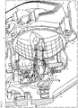
- the motorcycle headlight includes a lighting unit 2 in the middle area, which is used to generate a low beam distribution.
- the lighting unit 2 is rotatably accommodated in a support frame 3, the back of which is covered by a housing 4.
- the lighting unit 2 is defined by those components which are rotatable relative to the support frame.
- the lighting unit 2 includes a free-form reflector 7 on which a screen 8 is arranged.
- the bezel includes a horizontal section behind which is mounted a multi-LED illuminant mounted on a heat sink, as illustrated in Figure 1 below 2 is described in more detail.
- the screen is open on the back, so that the light from the LEDs falls on the free-form reflector 7 and is deflected by it in such a way that a low-beam light distribution with a predetermined light-dark boundary is generated in front of the motorcycle.
- the lighting unit 2 takes over the generation of the low beam.
- the light modules 5 are also switched on, with a pair of these light modules being located to the left and a pair of these light modules to the right of the central lighting unit 2 .
- the motorcycle headlight 1 also includes a daytime running light in the form of two optical fibers 6 , one optical fiber being arranged to the left and the other optical fiber to the right of the central lighting unit 2 .
- the light modules 5 used for the high beam and the daytime running light 6 are rigidly attached to the support frame, i.e. they cannot rotate relative to the support frame, as is the case with the light unit 2 .
- the detailed structure of the lighting unit 2 is from the perspective sectional view of FIG 2 apparent.
- the image was cut along a vertical plane that runs essentially centrally through the reflector 7 .
- Out of 2 it can be seen that the aperture 8 on the back is open.
- the front end of a heat sink 11 is pushed into the open area, on the top and bottom of which there is a printed circuit board 10 with LEDs arranged thereon.
- the screen 8 prevents a user from being able to see the LEDs directly.
- the LEDs are supplied with power via a cable 9 .
- the heat sink 11 serves to dissipate the heat generated during operation of the LEDs. It consists of a flat section on which the circuit boards 10 are located on the top and bottom and a round section which is arranged at the rear end of the flat section. The round section is rotatably connected to the supporting frame 3 on its rear side by means of an annular ball bearing 22 . This is from the below described 4 closer visible.
- the heat sink 11 is firmly screwed to a gear wheel component 12 on the back. Between the outer peripheral edge of the gear member 12 and the back of the ball bearing 22 is the inner circular edge of a press-in member 13 which is bolted to the support frame 3 is. The lighting unit 2 together with the ball bearing 22 is held in the support frame 3 by the press-in component.
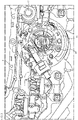
- FIG. 3 shows a rear view of the lighting unit 2 2 .
- the gear wheel component 12 is screwed to the heat sink 11 via screws 19 .
- the gear component 12 also has a central opening through which part of the heat sink 11 can be seen.
- a gear wheel segment 17 with a plurality of teeth 18 is located at the central opening.
- the gear wheel segment extends over an angular range of approximately 90°.
- the press-in component 13 is firmly screwed to the supporting frame 3 via screws 20 .
- a simple mechanism using an electromechanical actuator 14 is used to effect a roll angle compensation, i.e. a rotation of the lighting unit 2 relative to the rest of the headlight around the longitudinal axis of the motorcycle.
- the electromechanical actuator includes a toothed rack 15 which can be displaced in the longitudinal direction when the actuator 14 is activated. On its underside, the toothed rack has a multiplicity of teeth 16 which engage in the teeth 18 of the toothed wheel segment 17 . Except for the use of the toothed rack, the structure of the electromechanical actuator is known per se. In particular, an actuator can be used that is used in other vehicles for headlight range adjustment.
- a curved element 21 is formed on the back of the press-in component 13, which serves as an abutment for the rack and exerts a compressive force on it, so that a power transmission between the teeth 16 of the rack 15 and the teeth 18 of the gear segment 17 takes place.
- the actuation of the electromechanical actuator 14 shifts the toothed rack 15 and converts a translational movement via the engagement of the teeth 16 into the teeth 18 into a rotary movement of the gear wheel component 17 and thus of the entire lighting unit 2 .
- the electromechanical actuator is controlled during operation of the motorcycle in such a way that a roll angle compensation is automatically achieved, ie the actuator causes the lighting unit to rotate against the motorcycle's inclined position so that the course of the light-dark boundary of the low beam distribution remains unchanged.
- the structure of the ring-shaped ball bearing 22 can also be seen again.
- the ball bearing comprises an inner ring 23 and an outer ring 24, between which the balls 25 are located.
- the inner ring 23 is pressed against the heat sink 11 via the gear member 17 and thus moves together with the gear member and the heat sink.
- the outer ring 24 is pressed against the support frame 3 via the press-in component 13, so that the outer ring is held stationary in the support frame.
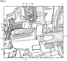
- figure 5 12 shows the structure of the above-mentioned electromechanical actuator 26 in an oblique view from behind.
- the housing 4 provided on the back of the headlight can also be seen.
- the electromechanical actuator 26, whose drive can be configured in exactly the same way as in the actuator 14, is held rigidly in the housing 4.
- the activation of the actuator 26 causes a displacement of a rod 27 which is located in a seat 28 on the support frame 3 and comprises a ball (not shown) at the front end.
- the support frame 3 is also mounted at four points via ball screws 29 on the housing 4 such that it can be tilted figure 5 only a ball screw is visible in the section.
- the support frame 3 is pivoted about a horizontal axis which runs perpendicular to the longitudinal axis of the motorcycle. This tilting allows a change in the pitch angle of the motorcycle and thus a height adjustment of the generated light distribution.
- the lighting unit 2 which is used to generate the low beam
- four further lighting modules 5 are provided in the support frame 3 for generating the high beam. Consequently, the tilting of the support frame 3 causes a height adjustment of both the low beam and the high beam.
- a motorcycle headlight is created with a simple mechanical structure for effecting roll angle compensation with a large rotation angle range (approximately ⁇ 35°).
- the mechanics are based on the conversion of a translational movement into a rotary movement through the interaction of a toothed rack with a gear wheel.
- This simple mechanism enables a compact design of the headlight.
- several components of the headlight can be reused in different headlight types in the manner of a modular system.
Landscapes
- Engineering & Computer Science (AREA)
- Mechanical Engineering (AREA)
- General Engineering & Computer Science (AREA)
- Physics & Mathematics (AREA)
- Microelectronics & Electronic Packaging (AREA)
- Optics & Photonics (AREA)
- Non-Portable Lighting Devices Or Systems Thereof (AREA)
- Lighting Device Outwards From Vehicle And Optical Signal (AREA)
Claims (12)
- Phare pour une motocyclette, comprenant- une unité d'éclairage (2) pourvue d'un moyen d'éclairage (10) et d'un dispositif optique (7) afin de générer au moyen du dispositif optique (7) une distribution de lumière prédéfinie devant la motocyclette à partir de la lumière du moyen d'éclairage (10), dans lequel l'unité d'éclairage (2) est fixée sur un cadre de support (3) et peut tourner par rapport au cadre de support (3) de telle sorte que la rotation de l'unité d'éclairage (2) provoque le pivotement de la distribution de lumière prédéfinie dans un plan qui s'étend de manière substantiellement perpendiculaire au sens de la marche de la motocyclette ;- un actionneur électromécanique (14) pour provoquer la rotation de l'unité d'éclairage (2) en vue du pivotement de la distribution de lumière prédéfinie, l'actionneur électromécanique (14) comprenant une crémaillère (15) qui peut être déplacée par l'activation de l'actionneur (14) ;caractérisé en ce que la crémaillère (15) vient en prise avec un segment de roue dentée (17) de l'unité d'éclairage (2) de sorte que le déplacement de la crémaillère (15) provoque la rotation de l'unité d'éclairage (2) en vue du pivotement de la distribution de lumière prédéfinie.
- Phare selon la revendication 1, caractérisé en ce que l'actionneur électromécanique (14) peut être piloté par l'intermédiaire d'un dispositif de commande de telle sorte que dans une position inclinée de la motocyclette pendant le déplacement, l'actionneur électromécanique (14) fait tourner l'unité d'éclairage (2) à l'opposé de la direction de la position inclinée.
- Phare selon la revendication 1 ou 2, caractérisé en ce que l'unité d'éclairage (2) est montée en rotation dans le cadre de support (3), au moyen d'un palier (22), de préférence d'un roulement à billes et/ou d'un palier à roulement.
- Phare selon l'une quelconque des revendications précédentes, caractérisé en ce que l'unité d'éclairage (2) présente un dissipateur de chaleur (11) qui est disposé sur le moyen d'éclairage (10), dans lequel le dissipateur de chaleur (11) est relié rigidement à un composant de roue dentée (12) qui présente le segment de roue dentée (17), ou dans lequel le segment de roue dentée (17) est réalisé d'un seul tenant avec le dissipateur de chaleur (11).
- Phare selon l'une quelconque des revendications précédentes, caractérisé en ce que l'actionneur électromécanique (14) est disposé de façon adjacente à un composant (13) qui présente un palier de butée (21) qui pousse la crémaillère (15) de l'actionneur électromécanique (14) contre le segment de roue dentée (17) .
- Phare selon la revendication 5, caractérisé en ce que le composant (13) est relié rigidement au cadre de support (3) et maintient l'unité d'éclairage (2) dans le cadre de support (3).
- Phare selon l'une quelconque des revendications précédentes, caractérisé en ce que le dispositif optique (7) comprend un réflecteur, le réflecteur étant de préférence un réflecteur de forme libre qui génère par réflexion de la lumière du moyen d'éclairage (10) directement sans lentille la distribution de lumière prédéfinie devant la motocyclette.
- Phare selon l'une quelconque des revendications précédentes, caractérisé en ce que le moyen d'éclairage (10) comprend une ou plusieurs LED et/ou diodes laser.
- Phare selon l'une quelconque des revendications précédentes, caractérisé en ce que l'unité d'éclairage (2) est réalisé pour générer une distribution de feu de croisement, dans lequel de préférence une ou plusieurs autres unités d'éclairage (5) sont disposées sur le cadre de support pour générer une distribution de feu de route.
- Phare selon l'une quelconque des revendications précédentes, caractérisé en ce que le phare comprend un boîtier (4) auquel le cadre de support (3) est fixé de telle sorte qu'il est basculant par rapport au boîtier (4) autour d'un axe de basculement qui s'étend de manière substantiellement horizontale et verticale par rapport à l'axe longitudinal dans une position redressée de la motocyclette, dans lequel un autre actionneur électromécanique (26) est prévu pour le basculement du cadre de support (3) afin de provoquer un réglage de la hauteur de la distribution de lumière prédéfinie.
- Phare selon la revendication 10, caractérisé en ce que l'autre actionneur électromécanique (26) est fixé rigidement au boîtier (4), dans lequel une tige d'actionnement mobile (27) de l'autre actionneur électromécanique (26) interagit avec le cadre de support (3) afin de provoquer le basculement du cadre de support (3).
- Motocyclette, caractérisée en ce que la motocyclette comprend un phare selon l'une quelconque des revendications précédentes.
Applications Claiming Priority (2)
| Application Number | Priority Date | Filing Date | Title |
|---|---|---|---|
| DE102018128493.4A DE102018128493A1 (de) | 2018-11-14 | 2018-11-14 | Scheinwerfer für ein Motorrad |
| PCT/EP2019/079074 WO2020099094A1 (fr) | 2018-11-14 | 2019-10-24 | Phare pour une motocyclette |
Publications (2)
| Publication Number | Publication Date |
|---|---|
| EP3880548A1 EP3880548A1 (fr) | 2021-09-22 |
| EP3880548B1 true EP3880548B1 (fr) | 2022-11-23 |
Family
ID=68382445
Family Applications (1)
| Application Number | Title | Priority Date | Filing Date |
|---|---|---|---|
| EP19794978.7A Active EP3880548B1 (fr) | 2018-11-14 | 2019-10-24 | Phare pour une motocyclette |
Country Status (3)
| Country | Link |
|---|---|
| EP (1) | EP3880548B1 (fr) |
| DE (1) | DE102018128493A1 (fr) |
| WO (1) | WO2020099094A1 (fr) |
Families Citing this family (1)
| Publication number | Priority date | Publication date | Assignee | Title |
|---|---|---|---|---|
| DE102022125785A1 (de) | 2022-10-06 | 2024-04-11 | Bayerische Motoren Werke Aktiengesellschaft | Scheinwerfer für ein Fahrzeug sowie Motorrad |
Family Cites Families (5)
| Publication number | Priority date | Publication date | Assignee | Title |
|---|---|---|---|---|
| JPH0762962B2 (ja) * | 1986-12-20 | 1995-07-05 | 株式会社小糸製作所 | 車輌用前照灯 |
| JPH0825417B2 (ja) * | 1987-08-17 | 1996-03-13 | 株式会社小糸製作所 | 二輪車輌用前照灯の照射角修正装置 |
| KR20120035644A (ko) * | 2010-10-06 | 2012-04-16 | 이종목 | 도로 적응형 오토바이 조명등 |
| DE102013216584B4 (de) | 2013-08-21 | 2025-10-02 | Bayerische Motoren Werke Aktiengesellschaft | Scheinwerfer für ein Motorrad |
| CZ2015531A3 (cs) * | 2015-07-30 | 2016-10-19 | Varroc Lighting Systems Sro | Světelné zařízení, zejména světlomet pro motorová vozidla |
-
2018
- 2018-11-14 DE DE102018128493.4A patent/DE102018128493A1/de active Pending
-
2019
- 2019-10-24 WO PCT/EP2019/079074 patent/WO2020099094A1/fr not_active Ceased
- 2019-10-24 EP EP19794978.7A patent/EP3880548B1/fr active Active
Also Published As
| Publication number | Publication date |
|---|---|
| DE102018128493A1 (de) | 2020-05-14 |
| EP3880548A1 (fr) | 2021-09-22 |
| WO2020099094A1 (fr) | 2020-05-22 |
Similar Documents
| Publication | Publication Date | Title |
|---|---|---|
| EP1234716B1 (fr) | Phare de véhicule | |
| DE202015009749U1 (de) | Drehbares Beleuchtungs- und/oder Signalisierungsmodul mit feststehender Lichtquelle | |
| DE102014200237B4 (de) | Scheinwerfer eines Kraftfahrzeugs | |
| DE112014002157T5 (de) | Fahrzeugvorderlichteinheit, Fahrzeugvorderlichteinheit und Fahrzeugvorderlichtgerät | |
| DE4446978A1 (de) | Einstellmechanismus für einen Fahrzeugscheinwerfer | |
| DE102005046037B4 (de) | Beleuchtungseinrichtung für einspurige Kraftfahrzeuge | |
| DE102007007839A1 (de) | Fahrzeugscheinwerfer | |
| DE102018216212B4 (de) | Fahrzeugleuchte | |
| DE69809816T2 (de) | Fahrzeug-Scheinwerfer | |
| WO2013123537A1 (fr) | Dispositif d'éclairage pour véhicule automobile | |
| DE102017115699A1 (de) | Lichtmodul eines Kraftfahrzeugscheinwerfers und Kraftfahrzeugscheinwerfer mit einem solchen Lichtmodul | |
| EP3880548B1 (fr) | Phare pour une motocyclette | |
| EP2886394B1 (fr) | Dispositif d'éclairage pour un phare de véhicule automobile | |
| DE102005013367B4 (de) | Vorrichtung zur Justierung von Reflektoren in Scheinwerfern für Kraftfahrzeuge | |
| DE102011003910B4 (de) | Scheinwerfer eines Kraftfahrzeugs | |
| DE10217191A1 (de) | Scheinwerfer | |
| DE102013216584B4 (de) | Scheinwerfer für ein Motorrad | |
| EP3631288B1 (fr) | Module d'éclairage à del pour un phare de véhicule à moteur | |
| EP3668751B1 (fr) | Phare conçu pour un véhicule | |
| DE102008011170B4 (de) | Scheinwerfer, insbesondere Kraftfahrzeugscheinwerfer | |
| DE102009051026B4 (de) | LED-Beleuchtungsvorrichtung umfassend wenigstens eine LED und eine Platine, auf der die LED angeordnet ist, und Kraftfahrzeug | |
| EP1762774B1 (fr) | Projecteur | |
| EP1273477B1 (fr) | Dispositif et procédé d'éclairage d'une partie de l'environnement à l'avant du véhicule | |
| EP2789502B1 (fr) | Phare de véhicule | |
| EP1398210A2 (fr) | Projecteur pour véhicule |
Legal Events
| Date | Code | Title | Description |
|---|---|---|---|
| STAA | Information on the status of an ep patent application or granted ep patent |
Free format text: STATUS: UNKNOWN |
|
| STAA | Information on the status of an ep patent application or granted ep patent |
Free format text: STATUS: THE INTERNATIONAL PUBLICATION HAS BEEN MADE |
|
| PUAI | Public reference made under article 153(3) epc to a published international application that has entered the european phase |
Free format text: ORIGINAL CODE: 0009012 |
|
| STAA | Information on the status of an ep patent application or granted ep patent |
Free format text: STATUS: REQUEST FOR EXAMINATION WAS MADE |
|
| 17P | Request for examination filed |
Effective date: 20210421 |
|
| AK | Designated contracting states |
Kind code of ref document: A1 Designated state(s): AL AT BE BG CH CY CZ DE DK EE ES FI FR GB GR HR HU IE IS IT LI LT LU LV MC MK MT NL NO PL PT RO RS SE SI SK SM TR |
|
| DAV | Request for validation of the european patent (deleted) | ||
| DAX | Request for extension of the european patent (deleted) | ||
| GRAP | Despatch of communication of intention to grant a patent |
Free format text: ORIGINAL CODE: EPIDOSNIGR1 |
|
| STAA | Information on the status of an ep patent application or granted ep patent |
Free format text: STATUS: GRANT OF PATENT IS INTENDED |
|
| INTG | Intention to grant announced |
Effective date: 20220719 |
|
| GRAS | Grant fee paid |
Free format text: ORIGINAL CODE: EPIDOSNIGR3 |
|
| GRAA | (expected) grant |
Free format text: ORIGINAL CODE: 0009210 |
|
| STAA | Information on the status of an ep patent application or granted ep patent |
Free format text: STATUS: THE PATENT HAS BEEN GRANTED |
|
| AK | Designated contracting states |
Kind code of ref document: B1 Designated state(s): AL AT BE BG CH CY CZ DE DK EE ES FI FR GB GR HR HU IE IS IT LI LT LU LV MC MK MT NL NO PL PT RO RS SE SI SK SM TR |
|
| REG | Reference to a national code |
Ref country code: GB Ref legal event code: FG4D Free format text: NOT ENGLISH |
|
| REG | Reference to a national code |
Ref country code: CH Ref legal event code: EP |
|
| REG | Reference to a national code |
Ref country code: DE Ref legal event code: R096 Ref document number: 502019006375 Country of ref document: DE |
|
| REG | Reference to a national code |
Ref country code: AT Ref legal event code: REF Ref document number: 1532985 Country of ref document: AT Kind code of ref document: T Effective date: 20221215 |
|
| REG | Reference to a national code |
Ref country code: IE Ref legal event code: FG4D Free format text: LANGUAGE OF EP DOCUMENT: GERMAN |
|
| REG | Reference to a national code |
Ref country code: LT Ref legal event code: MG9D |
|
| REG | Reference to a national code |
Ref country code: NL Ref legal event code: MP Effective date: 20221123 |
|
| PG25 | Lapsed in a contracting state [announced via postgrant information from national office to epo] |
Ref country code: SE Free format text: LAPSE BECAUSE OF FAILURE TO SUBMIT A TRANSLATION OF THE DESCRIPTION OR TO PAY THE FEE WITHIN THE PRESCRIBED TIME-LIMIT Effective date: 20221123 Ref country code: PT Free format text: LAPSE BECAUSE OF FAILURE TO SUBMIT A TRANSLATION OF THE DESCRIPTION OR TO PAY THE FEE WITHIN THE PRESCRIBED TIME-LIMIT Effective date: 20230323 Ref country code: NO Free format text: LAPSE BECAUSE OF FAILURE TO SUBMIT A TRANSLATION OF THE DESCRIPTION OR TO PAY THE FEE WITHIN THE PRESCRIBED TIME-LIMIT Effective date: 20230223 Ref country code: LT Free format text: LAPSE BECAUSE OF FAILURE TO SUBMIT A TRANSLATION OF THE DESCRIPTION OR TO PAY THE FEE WITHIN THE PRESCRIBED TIME-LIMIT Effective date: 20221123 Ref country code: FI Free format text: LAPSE BECAUSE OF FAILURE TO SUBMIT A TRANSLATION OF THE DESCRIPTION OR TO PAY THE FEE WITHIN THE PRESCRIBED TIME-LIMIT Effective date: 20221123 Ref country code: ES Free format text: LAPSE BECAUSE OF FAILURE TO SUBMIT A TRANSLATION OF THE DESCRIPTION OR TO PAY THE FEE WITHIN THE PRESCRIBED TIME-LIMIT Effective date: 20221123 |
|
| PG25 | Lapsed in a contracting state [announced via postgrant information from national office to epo] |
Ref country code: RS Free format text: LAPSE BECAUSE OF FAILURE TO SUBMIT A TRANSLATION OF THE DESCRIPTION OR TO PAY THE FEE WITHIN THE PRESCRIBED TIME-LIMIT Effective date: 20221123 Ref country code: PL Free format text: LAPSE BECAUSE OF FAILURE TO SUBMIT A TRANSLATION OF THE DESCRIPTION OR TO PAY THE FEE WITHIN THE PRESCRIBED TIME-LIMIT Effective date: 20221123 Ref country code: LV Free format text: LAPSE BECAUSE OF FAILURE TO SUBMIT A TRANSLATION OF THE DESCRIPTION OR TO PAY THE FEE WITHIN THE PRESCRIBED TIME-LIMIT Effective date: 20221123 Ref country code: IS Free format text: LAPSE BECAUSE OF FAILURE TO SUBMIT A TRANSLATION OF THE DESCRIPTION OR TO PAY THE FEE WITHIN THE PRESCRIBED TIME-LIMIT Effective date: 20230323 Ref country code: HR Free format text: LAPSE BECAUSE OF FAILURE TO SUBMIT A TRANSLATION OF THE DESCRIPTION OR TO PAY THE FEE WITHIN THE PRESCRIBED TIME-LIMIT Effective date: 20221123 Ref country code: GR Free format text: LAPSE BECAUSE OF FAILURE TO SUBMIT A TRANSLATION OF THE DESCRIPTION OR TO PAY THE FEE WITHIN THE PRESCRIBED TIME-LIMIT Effective date: 20230224 |
|
| P01 | Opt-out of the competence of the unified patent court (upc) registered |
Effective date: 20230502 |
|
| PG25 | Lapsed in a contracting state [announced via postgrant information from national office to epo] |
Ref country code: NL Free format text: LAPSE BECAUSE OF FAILURE TO SUBMIT A TRANSLATION OF THE DESCRIPTION OR TO PAY THE FEE WITHIN THE PRESCRIBED TIME-LIMIT Effective date: 20221123 |
|
| PG25 | Lapsed in a contracting state [announced via postgrant information from national office to epo] |
Ref country code: SM Free format text: LAPSE BECAUSE OF FAILURE TO SUBMIT A TRANSLATION OF THE DESCRIPTION OR TO PAY THE FEE WITHIN THE PRESCRIBED TIME-LIMIT Effective date: 20221123 Ref country code: RO Free format text: LAPSE BECAUSE OF FAILURE TO SUBMIT A TRANSLATION OF THE DESCRIPTION OR TO PAY THE FEE WITHIN THE PRESCRIBED TIME-LIMIT Effective date: 20221123 Ref country code: EE Free format text: LAPSE BECAUSE OF FAILURE TO SUBMIT A TRANSLATION OF THE DESCRIPTION OR TO PAY THE FEE WITHIN THE PRESCRIBED TIME-LIMIT Effective date: 20221123 Ref country code: DK Free format text: LAPSE BECAUSE OF FAILURE TO SUBMIT A TRANSLATION OF THE DESCRIPTION OR TO PAY THE FEE WITHIN THE PRESCRIBED TIME-LIMIT Effective date: 20221123 Ref country code: CZ Free format text: LAPSE BECAUSE OF FAILURE TO SUBMIT A TRANSLATION OF THE DESCRIPTION OR TO PAY THE FEE WITHIN THE PRESCRIBED TIME-LIMIT Effective date: 20221123 |
|
| REG | Reference to a national code |
Ref country code: DE Ref legal event code: R097 Ref document number: 502019006375 Country of ref document: DE |
|
| PG25 | Lapsed in a contracting state [announced via postgrant information from national office to epo] |
Ref country code: SK Free format text: LAPSE BECAUSE OF FAILURE TO SUBMIT A TRANSLATION OF THE DESCRIPTION OR TO PAY THE FEE WITHIN THE PRESCRIBED TIME-LIMIT Effective date: 20221123 Ref country code: AL Free format text: LAPSE BECAUSE OF FAILURE TO SUBMIT A TRANSLATION OF THE DESCRIPTION OR TO PAY THE FEE WITHIN THE PRESCRIBED TIME-LIMIT Effective date: 20221123 |
|
| PLBE | No opposition filed within time limit |
Free format text: ORIGINAL CODE: 0009261 |
|
| STAA | Information on the status of an ep patent application or granted ep patent |
Free format text: STATUS: NO OPPOSITION FILED WITHIN TIME LIMIT |
|
| 26N | No opposition filed |
Effective date: 20230824 |
|
| PG25 | Lapsed in a contracting state [announced via postgrant information from national office to epo] |
Ref country code: SI Free format text: LAPSE BECAUSE OF FAILURE TO SUBMIT A TRANSLATION OF THE DESCRIPTION OR TO PAY THE FEE WITHIN THE PRESCRIBED TIME-LIMIT Effective date: 20221123 |
|
| PG25 | Lapsed in a contracting state [announced via postgrant information from national office to epo] |
Ref country code: IT Free format text: LAPSE BECAUSE OF FAILURE TO SUBMIT A TRANSLATION OF THE DESCRIPTION OR TO PAY THE FEE WITHIN THE PRESCRIBED TIME-LIMIT Effective date: 20221123 Ref country code: MC Free format text: LAPSE BECAUSE OF FAILURE TO SUBMIT A TRANSLATION OF THE DESCRIPTION OR TO PAY THE FEE WITHIN THE PRESCRIBED TIME-LIMIT Effective date: 20221123 |
|
| REG | Reference to a national code |
Ref country code: CH Ref legal event code: PL |
|
| REG | Reference to a national code |
Ref country code: BE Ref legal event code: MM Effective date: 20231031 |
|
| PG25 | Lapsed in a contracting state [announced via postgrant information from national office to epo] |
Ref country code: LU Free format text: LAPSE BECAUSE OF NON-PAYMENT OF DUE FEES Effective date: 20231024 |
|
| PG25 | Lapsed in a contracting state [announced via postgrant information from national office to epo] |
Ref country code: LU Free format text: LAPSE BECAUSE OF NON-PAYMENT OF DUE FEES Effective date: 20231024 |
|
| PG25 | Lapsed in a contracting state [announced via postgrant information from national office to epo] |
Ref country code: CH Free format text: LAPSE BECAUSE OF NON-PAYMENT OF DUE FEES Effective date: 20231031 |
|
| PG25 | Lapsed in a contracting state [announced via postgrant information from national office to epo] |
Ref country code: CH Free format text: LAPSE BECAUSE OF NON-PAYMENT OF DUE FEES Effective date: 20231031 |
|
| PG25 | Lapsed in a contracting state [announced via postgrant information from national office to epo] |
Ref country code: BE Free format text: LAPSE BECAUSE OF NON-PAYMENT OF DUE FEES Effective date: 20231031 |
|
| PG25 | Lapsed in a contracting state [announced via postgrant information from national office to epo] |
Ref country code: IE Free format text: LAPSE BECAUSE OF NON-PAYMENT OF DUE FEES Effective date: 20231024 |
|
| PG25 | Lapsed in a contracting state [announced via postgrant information from national office to epo] |
Ref country code: IE Free format text: LAPSE BECAUSE OF NON-PAYMENT OF DUE FEES Effective date: 20231024 |
|
| PG25 | Lapsed in a contracting state [announced via postgrant information from national office to epo] |
Ref country code: BG Free format text: LAPSE BECAUSE OF FAILURE TO SUBMIT A TRANSLATION OF THE DESCRIPTION OR TO PAY THE FEE WITHIN THE PRESCRIBED TIME-LIMIT Effective date: 20221123 |
|
| PG25 | Lapsed in a contracting state [announced via postgrant information from national office to epo] |
Ref country code: BG Free format text: LAPSE BECAUSE OF FAILURE TO SUBMIT A TRANSLATION OF THE DESCRIPTION OR TO PAY THE FEE WITHIN THE PRESCRIBED TIME-LIMIT Effective date: 20221123 |
|
| PG25 | Lapsed in a contracting state [announced via postgrant information from national office to epo] |
Ref country code: CY Free format text: LAPSE BECAUSE OF FAILURE TO SUBMIT A TRANSLATION OF THE DESCRIPTION OR TO PAY THE FEE WITHIN THE PRESCRIBED TIME-LIMIT; INVALID AB INITIO Effective date: 20191024 |
|
| PG25 | Lapsed in a contracting state [announced via postgrant information from national office to epo] |
Ref country code: HU Free format text: LAPSE BECAUSE OF FAILURE TO SUBMIT A TRANSLATION OF THE DESCRIPTION OR TO PAY THE FEE WITHIN THE PRESCRIBED TIME-LIMIT; INVALID AB INITIO Effective date: 20191024 |
|
| PG25 | Lapsed in a contracting state [announced via postgrant information from national office to epo] |
Ref country code: TR Free format text: LAPSE BECAUSE OF FAILURE TO SUBMIT A TRANSLATION OF THE DESCRIPTION OR TO PAY THE FEE WITHIN THE PRESCRIBED TIME-LIMIT Effective date: 20221123 |
|
| REG | Reference to a national code |
Ref country code: AT Ref legal event code: MM01 Ref document number: 1532985 Country of ref document: AT Kind code of ref document: T Effective date: 20241024 |
|
| PGFP | Annual fee paid to national office [announced via postgrant information from national office to epo] |
Ref country code: DE Payment date: 20251021 Year of fee payment: 7 |
|
| PGFP | Annual fee paid to national office [announced via postgrant information from national office to epo] |
Ref country code: GB Payment date: 20251024 Year of fee payment: 7 |
|
| PG25 | Lapsed in a contracting state [announced via postgrant information from national office to epo] |
Ref country code: AT Free format text: LAPSE BECAUSE OF NON-PAYMENT OF DUE FEES Effective date: 20241024 |
|
| PGFP | Annual fee paid to national office [announced via postgrant information from national office to epo] |
Ref country code: FR Payment date: 20251024 Year of fee payment: 7 |
|
| PGFP | Annual fee paid to national office [announced via postgrant information from national office to epo] |
Ref country code: AT Payment date: 20260410 Year of fee payment: 5 |