EP3631416B1 - Verfahren zur analyse von mikroorganismen - Google Patents
Verfahren zur analyse von mikroorganismen Download PDFInfo
- Publication number
- EP3631416B1 EP3631416B1 EP18723872.0A EP18723872A EP3631416B1 EP 3631416 B1 EP3631416 B1 EP 3631416B1 EP 18723872 A EP18723872 A EP 18723872A EP 3631416 B1 EP3631416 B1 EP 3631416B1
- Authority
- EP
- European Patent Office
- Prior art keywords
- image
- sample
- microorganisms
- plane
- microorganism
- Prior art date
- Legal status (The legal status is an assumption and is not a legal conclusion. Google has not performed a legal analysis and makes no representation as to the accuracy of the status listed.)
- Active
Links
Images


Classifications
-
- G—PHYSICS
- G01—MEASURING; TESTING
- G01N—INVESTIGATING OR ANALYSING MATERIALS BY DETERMINING THEIR CHEMICAL OR PHYSICAL PROPERTIES
- G01N15/00—Investigating characteristics of particles; Investigating permeability, pore-volume or surface-area of porous materials
- G01N15/10—Investigating individual particles
- G01N15/14—Optical investigation techniques, e.g. flow cytometry
- G01N15/1434—Optical arrangements
-
- G—PHYSICS
- G01—MEASURING; TESTING
- G01N—INVESTIGATING OR ANALYSING MATERIALS BY DETERMINING THEIR CHEMICAL OR PHYSICAL PROPERTIES
- G01N15/00—Investigating characteristics of particles; Investigating permeability, pore-volume or surface-area of porous materials
- G01N15/10—Investigating individual particles
- G01N15/14—Optical investigation techniques, e.g. flow cytometry
- G01N15/1429—Signal processing
- G01N15/1433—Signal processing using image recognition
-
- C—CHEMISTRY; METALLURGY
- C12—BIOCHEMISTRY; BEER; SPIRITS; WINE; VINEGAR; MICROBIOLOGY; ENZYMOLOGY; MUTATION OR GENETIC ENGINEERING
- C12Q—MEASURING OR TESTING PROCESSES INVOLVING ENZYMES, NUCLEIC ACIDS OR MICROORGANISMS; COMPOSITIONS OR TEST PAPERS THEREFOR; PROCESSES OF PREPARING SUCH COMPOSITIONS; CONDITION-RESPONSIVE CONTROL IN MICROBIOLOGICAL OR ENZYMOLOGICAL PROCESSES
- C12Q1/00—Measuring or testing processes involving enzymes, nucleic acids or microorganisms; Compositions therefor; Processes of preparing such compositions
- C12Q1/02—Measuring or testing processes involving enzymes, nucleic acids or microorganisms; Compositions therefor; Processes of preparing such compositions involving viable microorganisms
- C12Q1/04—Determining presence or kind of microorganism; Use of selective media for testing antibiotics or bacteriocides; Compositions containing a chemical indicator therefor
- C12Q1/06—Quantitative determination
-
- G—PHYSICS
- G01—MEASURING; TESTING
- G01N—INVESTIGATING OR ANALYSING MATERIALS BY DETERMINING THEIR CHEMICAL OR PHYSICAL PROPERTIES
- G01N21/00—Investigating or analysing materials by the use of optical means, i.e. using sub-millimetre waves, infrared, visible or ultraviolet light
- G01N21/17—Systems in which incident light is modified in accordance with the properties of the material investigated
- G01N21/41—Refractivity; Phase-affecting properties, e.g. optical path length
- G01N21/45—Refractivity; Phase-affecting properties, e.g. optical path length using interferometric methods; using Schlieren methods
- G01N21/453—Holographic interferometry
-
- G—PHYSICS
- G02—OPTICS
- G02B—OPTICAL ELEMENTS, SYSTEMS OR APPARATUS
- G02B21/00—Microscopes
- G02B21/36—Microscopes arranged for photographic purposes or projection purposes or digital imaging or video purposes including associated control and data processing arrangements
- G02B21/365—Control or image processing arrangements for digital or video microscopes
- G02B21/367—Control or image processing arrangements for digital or video microscopes providing an output produced by processing a plurality of individual source images, e.g. image tiling, montage, composite images, depth sectioning, image comparison
-
- G—PHYSICS
- G03—PHOTOGRAPHY; CINEMATOGRAPHY; ANALOGOUS TECHNIQUES USING WAVES OTHER THAN OPTICAL WAVES; ELECTROGRAPHY; HOLOGRAPHY
- G03H—HOLOGRAPHIC PROCESSES OR APPARATUS
- G03H1/00—Holographic processes or apparatus using light, infrared or ultraviolet waves for obtaining holograms or for obtaining an image from them; Details peculiar thereto
- G03H1/0005—Adaptation of holography to specific applications
-
- G—PHYSICS
- G03—PHOTOGRAPHY; CINEMATOGRAPHY; ANALOGOUS TECHNIQUES USING WAVES OTHER THAN OPTICAL WAVES; ELECTROGRAPHY; HOLOGRAPHY
- G03H—HOLOGRAPHIC PROCESSES OR APPARATUS
- G03H1/00—Holographic processes or apparatus using light, infrared or ultraviolet waves for obtaining holograms or for obtaining an image from them; Details peculiar thereto
- G03H1/04—Processes or apparatus for producing holograms
- G03H1/0443—Digital holography, i.e. recording holograms with digital recording means
-
- G—PHYSICS
- G03—PHOTOGRAPHY; CINEMATOGRAPHY; ANALOGOUS TECHNIQUES USING WAVES OTHER THAN OPTICAL WAVES; ELECTROGRAPHY; HOLOGRAPHY
- G03H—HOLOGRAPHIC PROCESSES OR APPARATUS
- G03H1/00—Holographic processes or apparatus using light, infrared or ultraviolet waves for obtaining holograms or for obtaining an image from them; Details peculiar thereto
- G03H1/04—Processes or apparatus for producing holograms
- G03H1/08—Synthesising holograms, i.e. holograms synthesized from objects or objects from holograms
- G03H1/0866—Digital holographic imaging, i.e. synthesizing holobjects from holograms
-
- G—PHYSICS
- G01—MEASURING; TESTING
- G01N—INVESTIGATING OR ANALYSING MATERIALS BY DETERMINING THEIR CHEMICAL OR PHYSICAL PROPERTIES
- G01N15/00—Investigating characteristics of particles; Investigating permeability, pore-volume or surface-area of porous materials
- G01N15/10—Investigating individual particles
- G01N2015/1006—Investigating individual particles for cytology
-
- G—PHYSICS
- G01—MEASURING; TESTING
- G01N—INVESTIGATING OR ANALYSING MATERIALS BY DETERMINING THEIR CHEMICAL OR PHYSICAL PROPERTIES
- G01N15/00—Investigating characteristics of particles; Investigating permeability, pore-volume or surface-area of porous materials
- G01N15/10—Investigating individual particles
- G01N15/14—Optical investigation techniques, e.g. flow cytometry
- G01N15/1434—Optical arrangements
- G01N2015/1454—Optical arrangements using phase shift or interference, e.g. for improving contrast
-
- G—PHYSICS
- G01—MEASURING; TESTING
- G01N—INVESTIGATING OR ANALYSING MATERIALS BY DETERMINING THEIR CHEMICAL OR PHYSICAL PROPERTIES
- G01N21/00—Investigating or analysing materials by the use of optical means, i.e. using sub-millimetre waves, infrared, visible or ultraviolet light
- G01N21/17—Systems in which incident light is modified in accordance with the properties of the material investigated
- G01N21/47—Scattering, i.e. diffuse reflection
- G01N21/4788—Diffraction
-
- G—PHYSICS
- G03—PHOTOGRAPHY; CINEMATOGRAPHY; ANALOGOUS TECHNIQUES USING WAVES OTHER THAN OPTICAL WAVES; ELECTROGRAPHY; HOLOGRAPHY
- G03H—HOLOGRAPHIC PROCESSES OR APPARATUS
- G03H1/00—Holographic processes or apparatus using light, infrared or ultraviolet waves for obtaining holograms or for obtaining an image from them; Details peculiar thereto
- G03H1/0005—Adaptation of holography to specific applications
- G03H2001/0033—Adaptation of holography to specific applications in hologrammetry for measuring or analysing
-
- G—PHYSICS
- G03—PHOTOGRAPHY; CINEMATOGRAPHY; ANALOGOUS TECHNIQUES USING WAVES OTHER THAN OPTICAL WAVES; ELECTROGRAPHY; HOLOGRAPHY
- G03H—HOLOGRAPHIC PROCESSES OR APPARATUS
- G03H1/00—Holographic processes or apparatus using light, infrared or ultraviolet waves for obtaining holograms or for obtaining an image from them; Details peculiar thereto
- G03H1/0005—Adaptation of holography to specific applications
- G03H2001/005—Adaptation of holography to specific applications in microscopy, e.g. digital holographic microscope [DHM]
-
- G—PHYSICS
- G03—PHOTOGRAPHY; CINEMATOGRAPHY; ANALOGOUS TECHNIQUES USING WAVES OTHER THAN OPTICAL WAVES; ELECTROGRAPHY; HOLOGRAPHY
- G03H—HOLOGRAPHIC PROCESSES OR APPARATUS
- G03H1/00—Holographic processes or apparatus using light, infrared or ultraviolet waves for obtaining holograms or for obtaining an image from them; Details peculiar thereto
- G03H1/04—Processes or apparatus for producing holograms
- G03H1/0443—Digital holography, i.e. recording holograms with digital recording means
- G03H2001/0447—In-line recording arrangement
-
- G—PHYSICS
- G03—PHOTOGRAPHY; CINEMATOGRAPHY; ANALOGOUS TECHNIQUES USING WAVES OTHER THAN OPTICAL WAVES; ELECTROGRAPHY; HOLOGRAPHY
- G03H—HOLOGRAPHIC PROCESSES OR APPARATUS
- G03H1/00—Holographic processes or apparatus using light, infrared or ultraviolet waves for obtaining holograms or for obtaining an image from them; Details peculiar thereto
- G03H1/04—Processes or apparatus for producing holograms
- G03H1/08—Synthesising holograms, i.e. holograms synthesized from objects or objects from holograms
- G03H1/0866—Digital holographic imaging, i.e. synthesizing holobjects from holograms
- G03H2001/0883—Reconstruction aspect, e.g. numerical focusing
-
- G—PHYSICS
- G03—PHOTOGRAPHY; CINEMATOGRAPHY; ANALOGOUS TECHNIQUES USING WAVES OTHER THAN OPTICAL WAVES; ELECTROGRAPHY; HOLOGRAPHY
- G03H—HOLOGRAPHIC PROCESSES OR APPARATUS
- G03H2226/00—Electro-optic or electronic components relating to digital holography
- G03H2226/02—Computing or processing means, e.g. digital signal processor [DSP]
-
- G—PHYSICS
- G03—PHOTOGRAPHY; CINEMATOGRAPHY; ANALOGOUS TECHNIQUES USING WAVES OTHER THAN OPTICAL WAVES; ELECTROGRAPHY; HOLOGRAPHY
- G03H—HOLOGRAPHIC PROCESSES OR APPARATUS
- G03H2226/00—Electro-optic or electronic components relating to digital holography
- G03H2226/11—Electro-optic recording means, e.g. CCD, pyroelectric sensors
Definitions
- the technical field of the invention is the characterization of microorganisms, in particular the characterization of yeasts or bacteria.
- microorganisms such as yeasts or bacteria, or their derivatives
- yeasts are widespread in various sectors, such as bakery, wine production, brewing or even the manufacture of dairy products.
- the application of yeasts or bacteria concerns many foods by means of probiotics, the latter being for example added to cereals or to animal feed.
- probiotics the latter being for example added to cereals or to animal feed.
- industrial fields can use microorganisms. This is for example agriculture or horticulture, with the development of phytosanitary products or fertilizers more respectful of the environment, or the production of biofuels obtained from plants. Other applications relate to the field of pharmacy and medical diagnostics.
- the step of characterizing such microorganisms constitutes an essential link in the production chain.
- Microbiological controls are frequently used, on samples taken from culture media, in order to detect and enumerate living microorganisms. Cultivation on Petri dishes is still widely used, but has certain drawbacks, in particular the preparation, the duration of the analysis and the impossibility of detecting living and non-cultivable microorganisms.
- viability markers capable of varying the optical properties of microorganisms differently depending on whether they are dead or alive.
- Such markers can act on the color or fluorescence property of the microorganisms examined. But the detection step, carried out under a microscope, is generally long, the field of observation being small.
- the device presented is simple, and makes it possible to discriminate dead yeasts from living yeasts by offering a high field of observation.
- Methylene blue is mixed beforehand with the culture medium in which the yeasts examined are bathed.
- the method comprises acquiring an image of the culture medium by an image sensor, and applying a holographic propagation operator to the acquired image considering multiple propagation distances, so as to perform a digital focusing, which makes it possible to establish a so-called optimal distance.
- each yeast is classified into a living or dead category based on an indicator established from an image reconstructed at said optimum distance.
- the document WO2016 / 151249 describes a method of analyzing cells, placed in a culture medium, without labeling. The addition of a marker is considered, in this document, as being able to have consequences on the development of the cells.
- the document WO2016 / 151248 describes a method for identifying particles, for example blood particles, also avoiding prior labeling of the latter.
- the document WO2016 / 097092 describes a method of imaging in a defocused configuration, to identify a microorganism, from defocused images relative to a focus plane of an optical system.
- the inventors have proposed an alternative to the method described in the publication Feizi, cited above, so as to carry out a classification between dead and living microorganisms according to a simple and inexpensive method in terms of calculation time. Moreover, as described in the description, the method allows a more complete analysis of living microorganisms.
- characteristic quantity one understands for example a modulus or a phase of the light wave of exposure, or their combination.
- propagation operator By application of a propagation operator from an image, it is meant that the propagation operator is applied to said image or to an image resulting from a transformation of said image, for example a square root of said image, as well as a possible normalization of the image.
- Step f) can include identification of the dead microorganisms.
- Step g) then makes it possible to identify, among the microorganisms identified as being alive, the viable and non-cultivable microorganisms. It can be applied to each microorganism considered to be living following step f).
- the first observation image and the second observation image can be obtained by applying a propagation operator respectively from an image acquired at the first instant and from d 'an image acquired at the second instant.
- the first observation image can result from the image acquired during step b).
- the time interval between the first instant and the second instant can be between 5 hours and 70 hours.
- step d) the propagation operator is applied from the image acquired, during step b), according to a plurality of propagation distances, so as to obtain a stack complex images.
- the first observation image can be derived from the reference image, being for example the image of the module or the image of the phase of the reference image.
- Step c) can be implemented from a complex image of the stack of complex images resulting from step d), or from the complex reference image, by considering the modulus or the phase of said complex image.
- the viability marker induces a coloration of the microorganisms when they are dead, according to a spectral band of coloration.
- the illumination of the sample is carried out according to a spectral illumination band, the illumination spectral band not comprising all or part of the spectral coloration band.
- no magnification or image formation optics extend between the image sensor and the sample, when the latter is held on the support.
- an imaging optical system is disposed between the sample and the image sensor, the optical system having an object focal plane, the sample extending in a plane of the sample. , the device being arranged such that the sample plane is offset from the object focal plane.
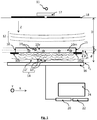
- the figure 1 represents an example of a device according to the invention.
- a light source 11 is capable of emitting a light wave 12, called an incident light wave, propagating in the direction of a sample 10, along a propagation axis Z.
- the light wave is emitted according to a spectral illumination band ⁇ .
- Sample 10 is a sample that it is desired to characterize. It comprises in particular a medium 10 m in which microorganisms 10 i bathe.
- the 10m medium is generally a culture medium, comprising nutrients allowing the development of microorganisms.
- microorganism is meant in particular a yeast, a bacterium, a spore, a fungus or a cell, whether it is a eukaryotic or prokaryotic cell, or a microalga.
- the sample also comprises a 10 v viability marker, the latter being capable of modifying an optical property of a microorganism 10 i in a different way depending on whether the microorganism is alive or dead.
- a 10 v viability marker capable of modifying an optical property of a microorganism 10 i in a different way depending on whether the microorganism is alive or dead.
- the modification of the visual appearance is meant for example a modification of the color of the microorganism.
- the use of such viability markers is well known. It can be methylene blue, or trypan blue.
- the modification of the optical property can also be a modification of the intensity of fluorescence light emitted by a microorganism analyzed using for example a viability indicator, sometimes designated by the term fluorogenic label, examples of such labels being described.
- WO9855861A1 or in the publication Kwolek-Mirek M "comparison of methods used for assessing the viability and vitality of yeast cells", FEMS
- the sustainability indicator is 10 v methylene blue. Under its effect, dead microorganisms are colored in a spectral band of ⁇ 'coloration, in this case blue, while living microorganisms remain translucent.
- the sample 10 is, in this example, contained in a fluid chamber 15.
- the thickness e of the sample 10, along the axis of propagation typically varies between 10 ⁇ m and 1 cm, and is preferably between 20 ⁇ m and 500 ⁇ m.
- the sample extends along a plane P 10 , called the plane of the sample, perpendicular to the axis of propagation Z. It is maintained on a support 10s at a distance d from an image sensor 16.
- the concentration of microorganisms can vary between 500 per microliter and 5000 per microliter.
- the distance D between the light source 11 and the fluidic chamber 15 is preferably greater than 1 cm. It is preferably between 2 and 30 cm.
- the light source, seen by the sample is considered to be point. This means that its diameter (or its diagonal) is preferably less than a tenth, better still a hundredth of the distance between the fluidic chamber 15 and the light source.
- the source of light is a light emitting diode. It is generally associated with diaphragm 18, or spatial filter.
- the aperture of the diaphragm is typically between 5 ⁇ m and 1 mm, preferably between 50 ⁇ m and 500 ⁇ m. In this example, the diaphragm is supplied by Thorlabs under the reference P150S and its diameter is 150 ⁇ m.
- the diaphragm can be replaced by an optical fiber, a first end of which is placed facing the light source 11 and a second end of which is placed opposite the sample 10.
- the device shown in FIG. figure 1 also comprises a diffuser 17, arranged between the light source 11 and the diaphragm 18.
- the function of such a diffuser is to distribute the light beam produced by an elementary light source 11 according to a cone of angle ⁇ .
- the scattering angle a varies between 10 ° and 80 °.
- the light source can be a laser source, such as a laser diode. In this case, it is not useful to associate a spatial filter or a diffuser with it.
- the emission spectral band ⁇ of the incident light wave 12 has a width of less than 100 nm.
- spectral bandwidth is meant a width at half the height of said spectral band.
- the light source 11 comprises several elementary light sources 11 k , each being able to emit an incident light wave 12 k in a spectral band ⁇ k .
- the spectral bands ⁇ k of the different light sources 11 k are different from each other.
- the sample 10 is placed between the light source 11 and the image sensor 16 previously mentioned.
- the latter preferably extends parallel, or substantially parallel to the plane P 10 along which the sample extends.
- substantially parallel means that the two elements need not be strictly parallel, an angular tolerance of a few degrees, less than 20 ° or 10 ° being allowed.
- the sample extends along an XY plane, perpendicular to the axis of propagation Z.
- the image sensor 16 is able to form an image I 0 of the sample 10 according to a detection plane P 0 .
- a detection plane P 0 is an image sensor comprising a matrix of pixels, of the CCD type or a CMOS.
- the detection plane P 0 preferably extends perpendicularly to the axis of propagation Z of the incident light wave 12.
- the distance d between the sample 10 and the matrix of pixels of the image sensor 16 is preferably between 50 ⁇ m and 2 cm, preferably between 100 ⁇ m and 2 mm.
- the image acquired by the image sensor comprises interference figures (or diffraction figures), each interference figure possibly being associated with a microorganism 10 i of the sample.
- the processor is a microprocessor connected to a programmable memory 22 in which is stored a sequence of instructions for perform the image processing and calculation operations described in this description.
- the processor can be coupled to a screen 24 allowing the display of images acquired by the image sensor 16 or calculated by the processor 20.
- An image I 0 acquired by the image sensor 16, also called a hologram, does not make it possible to obtain a sufficiently precise representation of the observed sample.
- a holographic propagation operator h it is possible to apply, to each image acquired by the image sensor, a holographic propagation operator h, so as to calculate a quantity representative of the exposure light wave 14.
- the coordinates (x, y) denote a radial position in a radial plane XY perpendicular to the axis of propagation Z.
- the coordinate z denotes a coordinate along the axis of propagation Z.
- the complex expression A is a complex quantity whose argument and modulus are respectively representative of the phase and of the intensity of the exposure light wave 14 detected by the image sensor 16.
- the convolution product of the image I 0 by the propagation operator h makes it possible to obtain a complex image A z representing a spatial distribution of the complex expression A in a reconstruction plane P z , extending at a distance
- the complex image A z corresponds to a complex image of the sample in the reconstruction plane P z . It also represents a two-dimensional spatial distribution of the optical properties of the exposure wave 14.
- Such a method, designated by the term holographic reconstruction makes it possible in particular to reconstruct an image of the modulus or of the phase of the exposure light wave. 14 in the reconstruction plan
- the method may include acquiring an image of the sample at a second instant t 2 , the second instant being after the first instant t 1 , and obtaining a second observation image I ( t 2 ) associated with the second instant.
- the comparison of the observation images respectively associated with the first and the second instant makes it possible to identify, among the microorganisms considered to be living, the viable microorganisms which cannot be cultivated.
- VNC viable and non-cultivable microorganism
- Step 100 Acquisition of an image I 0 of the sample 10 by the image sensor 16, this image forming a hologram.
- One of the advantages of the lens-less configuration, shown on figure 1 is the large field observed, making it possible to simultaneously address a high sample volume. This makes it possible to observe several microorganisms simultaneously, and thus to obtain a rapid characterization of the sample.
- the observed field depends on the size of the image sensor, being slightly smaller than the detection surface of the latter, due to the spacing between the pixels of the sensor and the sample.
- the observed field is generally greater than 10 mm 2 , and is typically between 10 mm 2 and 50 mm 2 , which is significantly higher than with a microscope.
- this image is acquired at a first instant t 1 and can be denoted I 0 ( t 1 ).
- Step 110 Formation of a reference image.
- the acquired image I 0 may include a large number of interference figures, and may not be easily used to locate the microorganisms present in the observed field. The latter are more easily identifiable from a complex image reconstructed by applying a holographic propagation operator to the acquired image.
- this complex image is a reference image A ref , obtained by performing a holographic reconstruction in a reference plane P ref to an image obtained from the acquired image I 0 .
- a first solution is to apply the propagation operator to the acquired image I 0 , or preferably to the square root of the acquired image I 0 , possibly normalized by the mean value I 0 of the acquired image.
- the reference image A ref is a complex image comprising phase and amplitude information of the light wave 14 to which the image sensor 16 is exposed.
- the reference plane is a plane advantageously perpendicular to the axis. propagation Z, and / or parallel to the detection plane P 0 . This is preferably the plane of the sample P 10 . Indeed, it is generally in this plane that the spatial resolution of a reconstructed complex image is best, such a principle being the basis of so-called digital focusing algorithms.
- the acquired image does not contain any information relating to the phase of the exposure wave 14. Therefore, the holographic reconstruction is carried out on the basis of incomplete optical information, based solely on the. intensity of the light wave collected on the image sensor.
- the improvement of the quality of the holographic reconstruction has been the subject of numerous developments, by implementing algorithms frequently referred to as “Phase retrieval”, allowing an estimate of the phase of the light wave at which the image sensor is exposed.
- This type of algorithm makes it possible to limit the reconstruction noise affecting the reconstructed complex image A ref .
- An example of a usable algorithm is for example described in US2012 / 0218379 .
- the sample is illuminated successively or simultaneously in different spectral bands ⁇ ⁇ k , and an image I 0 ( ⁇ ⁇ k ) representative of each spectral band is acquired in the detection plane P 0.
- the algorithm makes it possible to obtain a complex image A ref ( ⁇ ⁇ k ) of sample 10, in the reference plane, in each spectral band ⁇ ⁇ k .
- the complex images thus obtained can be combined, for example by taking an average, in each pixel, of their modulus and of their phase, which makes it possible to form the reference image A ref .
- the complex reference image is a complex image A ref ( ⁇ ⁇ k ) in a spectral band ⁇ ⁇ k .
- Another possibility which corresponds to the preferred embodiment, is to reconstruct a complex reference image based on an image acquired of the sample when the latter is illuminated in a single spectral band ⁇ .
- the complex reference image can be obtained using an iterative algorithm as described in the patent application FR1652500 filed on March 23, 2016 , and more precisely according to steps 110 to 160 described in said patent application.
- the coordinate z ref of the reference plane P ref is determined either a priori, in particular when the position of the sample is controlled with respect to the image sensor 16, or by means of digital focusing.
- the digital focusing makes it possible to define a focusing plane P focus reconstructing several images and defining a sharpness criterion for each reconstructed image.
- the focusing plane P focus corresponds to that in which the reconstructed image exhibits an optimum sharpness criterion. It corresponds to the plane in which a majority of microorganisms extend.
- the reference image A ref is then formed in a reference plane P ref corresponding to the focusing plane P focus .
- the focusing plane corresponds to a plane along which the sample extends.
- the complex image A ref is referred to as a reference image, as it serves as the basis for the formation of profiles on the basis of which the microorganisms in the sample are characterized.
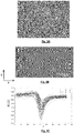
- the figure 3A shows an image of the module M ref of the complex reference image obtained by implementing the algorithm described in the previous paragraph.
- Step 120 construction of a stack of images.
- This step comprises an application of a propagation operator h to the complex reference image A ref so as to calculate complex images A ref, z , called secondary, along the axis of propagation Z.
- the complex reference image A ref is propagated along a plurality of reconstruction distances z, using a propagation operator h as defined above, so as to have a plurality of complex images, called secondary images , A ref, z reconstructed at the different distances z from the reference plane P ref .
- the values z min and z max are the minimum and maximum coordinates, along the Z axis, between which the complex reference image is propagated.
- the complex images are reconstructed according to a plurality of z coordinates between the sample 10 and the image sensor 16.
- the inventors have considered that it is preferable to obtain secondary complex images on either side of the body. reference plane P ref , so that z min ⁇ z ref ⁇ z max .
- the complex reference image correctly describes the exposure light wave 14, in particular at the level of its phase.
- the secondary complex images A ref, z obtained by propagation of the reference image, form a good descriptor of the propagation of the exposure light wave 14 along the propagation axis Z.
- the secondary complex images are calculated rapidly, without requiring the implementation of an iterative method such as that implemented to calculate the complex reference image A ref .
- the method consisting in applying an iterative algorithm to establish a complex reference image A ref (step 110) and then obtaining secondary complex images by applying a propagation operator h to the complex reference image, makes it possible to obtain a stack of complex images A ref, z by optimizing the calculation means.
- two adjacent reconstruction planes are spaced apart from each other according to a fine mesh, for example between 5 ⁇ m and 50 ⁇ m, and for example 25 ⁇ m.
- This is a local propagation, since it is carried out at a distance of between 500 ⁇ m and 2 ⁇ m on either side of the reference plane P ref , for example at ⁇ 500 ⁇ m.
- the complex reference image A ref is propagated along forty reconstruction planes P ref, z , so as to form as many secondary complex images, A ref, z .
- the steps 110 and 120 can be replaced by a propagation from the image I 0 acquired during the step 100, according to the step 110 ′ shown in the diagram. figure 2 .
- the propagation can be done for example by applying a propagation operator to the square root I 0 of this image, possibly normalized by the mean value I 0 according to different propagation distances z 1 .... z n .
- It can be a simple application of a propagation operator h, in which case the reconstructed images A z 1 ... A z not , forming the stack of complex images, can be affected by significant reconstruction noise.
- It can also be an implementation of an iterative holographic reconstruction algorithm, for example one of the algorithms mentioned above, according to different propagation distances z 1 ....
- Step 130 detection of microorganisms in the sample.
- This step aims to detect each microorganism present in the sample. It is performed from an observation image I ( t 1 ), called the first observation image, formed from an image I 0 ( t 1 ) acquired by the image sensor at a first acquisition instant t 1 ' or from a complex image formed from the latter.
- the image I 0 ( t 1 ) corresponds to the image I 0 acquired during step 100 and the first observation image I ( t 1 ) results from this image acquired I 0 , or of a complex image of the stack of images formed during step 120. It is preferable that the observation image I ( t 1 ) be established from the module and / or from the phase of a complex image reconstructed in a plane along which the sample extends.
- the first observation image I ( 1 ) can be the image of the module M ref of the complex reference image A ref , or the image M ref, z of the module of another complex image of the stack of images formed during step 120. It can also be the image ⁇ ref of the phase of the complex image of reference A ref , or the image ⁇ ref , z of the phase of another complex image of the stack of images formed during step 120.
- the observation image is obtained from the modulus and / or the phase of a complex image resulting from a propagation of an image I 0 acquired by the image sensor 16.
- each microorganism is carried out either manually by an operator, or automatically, by a morphological analysis on the first observation image I ( t 1 ), taking into account the fact that each microorganism 10 i can be associated, in the observation image, to a region of interest ROI i of predetermined shape, which can be easily detected. It may for example be a circular or ellipsoidal shape, or the like.
- the method can automatically detect each region of interest ROI i by taking into account one or more morphological criteria corresponding to a microorganism 10 j , for example its area and its eccentricity.
- Each region of interest ROI i detected corresponds to at least one 10 j microorganism.
- Algorithms based on spatial correlation with predetermined shapes of regions of interest can also be implemented.
- the volume of the sample 10 in the field of observation of the image sensor 16 being known, this step allows an estimate of a quantity N i or of a concentration of microorganisms 10 i in the sample.
- the figure 3A corresponds to an image of the module M ref of a complex reference image of a sample described below, in connection with the examples.
- the figure 3B corresponds to a detail of the figure 3A .
- Step 140 detection of the radial coordinates (x j , y i ) of each microorganism.
- the microorganisms 10 i being detected, via the regions of interest ROI i which are respectively associated with them on the first observation image 1 ( t 1 ), their position ( x i , y i ) in the radial plane XY , that is to say in a plane parallel to the detection plane, can be easily determined, for example by considering the centroid of the region of interest ROI i corresponding to each of them.
- Step 150 formation of a profile associated with each microorganism.
- a magnitude characteristic of the exposure light wave 14 is estimated at each radial position ( x i , y i ) selected during step 140, and at a plurality of distances z for reconstruction of the reference plane P ref , or of the detection plane P 0 , then a profile is formed representing an evolution of the characteristic quantity as a function of z, along the axis of propagation Z.
- the characteristic quantity can in particular be established from the modulus and phase of expression complex A describing the exposure light wave 14, using the images from the stack of complex images previously resulting from steps 120 or 110 '.
- the figures 3C and 3d respectively represent a profile M i (z) of the modulus and a profile ⁇ i ( z ) of the phase, passing through the radial positions ( x i , y i ) selected on the image 3B.
- Each profile is obtained from the images of the previously established complex image stack, by interpolating between the coordinates of two adjacent reconstructed images.
- Each profile is associated with a microorganism 10 i .
- Step 160 classification of each microorganism from the profiles formed during step 150.
- the profiles M i (z) describing the evolution of the modulus of the exposure light wave 14 can allow classification between dead microorganisms 10 i, d or living microorganisms 10 i , a .
- These profiles are represented on the figure 3C .
- a classification criterion is for example the maximum value taken by each profile M i ( z ) between the detection plane and the focusing plane.
- the method preferably comprises steps 170 and 180 aiming to identify, among the microorganisms considered to be alive at the end of step 160, the viable nonculturable microorganisms (VNC) mentioned above.
- VNC viable nonculturable microorganisms
- Step 170 acquisition of a delayed image I 0 ( t 2 ) .
- Step 130 a first observation image I ( t 1 ) has been formed, representing the sample at a first instant, this first instant being denoted t 1 .
- Step 170 comprises an acquisition, at a second acquisition instant t 2 , subsequent to the first acquisition instant t 1 , of a second image I 0 ( t 2 ) , called a deferred image, from sample 10 to using the image sensor 16.
- the inventors have observed that it was preferable for the time interval ⁇ t between the first instant t 1 and the second instant t 2 to be greater than 4 h, and preferably greater than 3 p.m. or 8 p.m.
- the time interval ⁇ t is between 4 and 72 hours, this interval being adjusted as a function of the time necessary for a division of the microorganism considered.
- Step 180 formation of a deferred observation image and classification of the living microorganisms.
- a second observation image I ( t 2 ) is formed.
- the second observation image I ( t 2 ) is preferably formed in the same way as the first observation image I ( t 1 ), so that the microorganisms are comparable on these two images.
- the microorganisms 10 i a considered to be alive are observed following step 160. Among these latter, the microorganisms whose morphology has varied compared to that observed in the first image are identified.
- observation I ( t 1 ) The variation in morphology, obtained by comparison between the first and the second observation image, must reflect at least one division of the microorganism during the time interval ⁇ t .
- the microorganisms 10 i , a considered to be alive are surrounded by a white frame, while the microorganisms 10 i , d considered to be dead are surrounded by a white circle.
- a comparison is made between the region of interest ROI i extending around the radial position at the first and second instants.
- microorganisms 10 i , a1 considered alive and cultivable are surrounded by a solid frame on the figure 4C while microorganisms 10 i , a2 considered viable non-culturable are surrounded by a dotted frame.
- the invention then allows an enumeration of three categories of microorganisms: dead, alive and cultivable, viable non-cultivable.
- the inventors have observed that the performance of the method is increased when the spectral illumination band ⁇ is different from the spectral coloration band ⁇ 'induced by the viability marker.
- the viability marker is methylene blue
- the spectral band of illumination is preferably located in the red or in the infrared.
- the illumination spectral band and the coloring spectral band do not overlap, or overlap marginally.
- overlapping marginally it is meant that the intersection between the two spectral bands is less than 10% or 20% of one of the two spectral bands.
- the method described above was compared with a visual characterization of microorganisms, the latter being observed under a microscope by an operator.
- the figure 4A represents a view under the microscope at the second instant t 2 .
- Visual characterization was used as a reference method, to qualify the method according to the invention.
- the high proportion of viable non-cultivable yeast is explained by a high temperature to which the sample was brought, causing stress favoring the viable non-cultivable state.
- the reliability of the method is therefore comparable to a conventional visual characterization carried out under a microscope. But due to the lensless imaging configuration, the observed field is significantly greater than the observed field resulting from the use of a microscope.
- the invention has for example made it possible to simultaneously characterize 11,574 yeasts distributed in the field of observation. The performance of the invention is therefore superior to the process visual in terms of the quantity of microorganisms characterized per unit of time.
- the algorithm can be automated, the reliability being demonstrated by the values in the previous table.
- an image formation optic is arranged between the sample and the image sensor, the image sensor being located in a so-called defocused configuration, the focal plane object of the optic being offset from the plane according to which extends the sample along a so-called defocus distance.
- the defocusing distance can be between 5 ⁇ m and 5 mm, and preferably between 10 ⁇ m and 2 mm.
- such a configuration makes it possible to obtain an image in which each microorganism appears in the form of a diffraction pattern, interference occurring between the light wave emitted by the source of light and propagating to the image sensor and a diffraction wave generated by each microorganism.
- the method described in connection with steps 100 to 180 is applicable to images acquired according to such a configuration. However, a lensless imaging configuration is preferred, due to the larger field of view that it provides.
- the invention applies to other organisms such as those listed above, when it is desired to obtain a rapid and reliable analysis in a important field of observation.
Landscapes
- Chemical & Material Sciences (AREA)
- Physics & Mathematics (AREA)
- General Physics & Mathematics (AREA)
- Engineering & Computer Science (AREA)
- Health & Medical Sciences (AREA)
- Life Sciences & Earth Sciences (AREA)
- Analytical Chemistry (AREA)
- Immunology (AREA)
- General Health & Medical Sciences (AREA)
- Biochemistry (AREA)
- Pathology (AREA)
- Organic Chemistry (AREA)
- Dispersion Chemistry (AREA)
- Multimedia (AREA)
- Zoology (AREA)
- Wood Science & Technology (AREA)
- Proteomics, Peptides & Aminoacids (AREA)
- Theoretical Computer Science (AREA)
- Computing Systems (AREA)
- Signal Processing (AREA)
- Computer Vision & Pattern Recognition (AREA)
- Microbiology (AREA)
- Molecular Biology (AREA)
- Biotechnology (AREA)
- Biophysics (AREA)
- Toxicology (AREA)
- Bioinformatics & Cheminformatics (AREA)
- General Engineering & Computer Science (AREA)
- Genetics & Genomics (AREA)
- Optics & Photonics (AREA)
- Apparatus Associated With Microorganisms And Enzymes (AREA)
- Investigating Or Analysing Materials By Optical Means (AREA)
- Measuring Or Testing Involving Enzymes Or Micro-Organisms (AREA)
Claims (14)
- Verfahren zur Analyse von Mikroorganismen (10 i ), wobei die Mikroorganismen in einer Probe angeordnet sind, wobei die Probe einen Lebensfähigkeitsmarker (10v) aufweist, der eine optische Eigenschaft der Mikroorganismen unterschiedlich ändern kann, je nachdem, ob sie tot oder lebendig sind, wobei das Verfahren die folgenden Schritte aufweist:a) Beleuchtung der Probe mit Hilfe einer Lichtquelle (11), wobei die Lichtquelle eine einfallende Lichtwelle (12) emittiert, die sich gemäß einer Ausbreitungsachse (Z) zur Probe (10) hin ausbreitet;b) Gewinnung, mit Hilfe eines Bildsensors (16), eines in einer Erfassungsebene (P 0) geformten Bilds (I 0) der Probe (10), wobei die Probe zwischen der Lichtquelle (11) und dem Bildsensor (16) angeordnet ist, wobei das Bild für eine Belichtungslichtwelle (14) repräsentativ ist, der der Bildsensor (16) unter der Wirkung der Beleuchtung ausgesetzt wird, wobei das Bild Interferenzfiguren zwischen einem Teil (12') der von der Probe übertragenen einfallenden Lichtwelle (12) und der Beugung der einfallenden Welle (12) durch die Mikroorganismen aufweist;wobei das Verfahren dadurch gekennzeichnet ist, dass es ebenfalls die folgenden Schritte enthält:c) Bestimmung radialer Positionen (x i, yi ) verschiedener Mikroorganismen (10 i ) in einer Ebene parallel zur Erfassungsebene, wobei jede radiale Position einem Mikroorganismus zugeordnet ist;d) ausgehend vom im Schritt b) gewonnenen Bild (I 0), Anwendung eines Ausbreitungsoperators (h), um mindestens eine charakteristische Größe (M, <p) der Belichtungslichtwelle (14) in jeder im Schritt c) bestimmten radialen Position (x i , y i ) und in einer Vielzahl von Abständen (z) der Erfassungsebene (P 0) zu berechnen;e) Formen eines Profils (M i (z), ϕi (z)), das eine Entwicklung der im Schritt d) berechneten charakteristischen Größe gemäß einer Achse parallel zur Ausbreitungsachse (Z) und durch jede im Schritt c) bestimmte radiale Position (x i , y i ) verlaufend darstellt, wobei jedes Profil einem Mikroorganismus (10 i ) zugeordnet ist;f) abhängig von jedem im Schritt e) geformten Profil, Klassifizierung zwischen den toten und lebenden Mikroorganismen.
- Verfahren nach Anspruch 1, das nach dem Schritt f) einen Schritt g) der Analyse der Fähigkeit des Mikroorganismus, sich zu teilen, aufweist, wobei der Schritt g) die folgenden Teilschritte für mindestens einen Mikroorganismus aufweist, der im Schritt f) als lebend angesehen wird:gi) Erhalt eines ersten Beobachtungsbilds (I(t 1)) der Probe zu einem ersten Zeitpunkt (t 1), wobei das Beobachtungsbild interessierende Bereiche (ROli) aufweist, die je Mikroorganismen (10 i ) zugeordnet sind, und Erfassung eines dem Mikroorganismus (10 i,a ) zugeordneten interessierenden Bereichs (ROIi );gii) Gewinnung eines Bilds der Probe (I 0(t 2)) zu einem zweiten Zeitpunkt (t2 ), wobei der zweite Zeitpunkt nach dem ersten Zeitpunkt liegt, und Erhalt eines zweiten Beobachtungsbilds (I(t 2)) der Probe ausgehend vom zum zweiten Zeitpunkt gewonnenen Bild (I 0(t 2)) der Probe;giii) Erfassung, auf dem zweiten Beobachtungsbild, eines interessierenden Bereichs (ROIi ) entsprechend dem Mikroorganismus (10 i,a );giv) Vergleich der in den Teilschritten gi) und giii) erfassten interessierenden Bereiche;gv) Bestimmung der Fähigkeit des Mikroorganismus, sich zu teilen, abhängig vom im Teilschritt giv) ausgeführten Vergleich.
- Verfahren nach Anspruch 2, wobei der Teilschritt gv) die Identifizierung unter den lebenden Mikroorganismen (10 i,a )von lebensfähigen und nicht kultivierbaren Mikroorganismen (10 i,a2) aufweist.
- Verfahren nach Anspruch 2 oder Anspruch 3, wobei in den Teilschritten gi) und gii) das erste Beobachtungsbild (I(t 1)) und das zweite Beobachtungsbild (I(t 2)) durch Anwenden eines Ausbreitungsoperators (h) ausgehend von einem zum ersten Zeitpunkt gewonnenen Bild (I 0(t 1)) bzw. ausgehend von dem zum zweiten Zeitpunkt gewonnenen Bild (I 0(t 2)) erhalten werden.
- Verfahren nach einem der Ansprüche 2 bis 4, wobei im Teilschritt gi) das erste Beobachtungsbild (I(t 1)) ausgehend vom im Schritt b) gewonnenen Bild (I 0) erhalten wird.
- Verfahren nach einem der Ansprüche 2 bis 5, wobei das Zeitintervall (Δt) zwischen dem ersten Zeitpunkt und dem zweiten Zeitpunkt zwischen 5 Stunden und 70 Stunden liegt.
- Verfahren nach einem der vorhergehenden Ansprüche, wobei im Schritt d) der Ausbreitungsoperator ausgehend vom im Schritt b) gewonnenen Bild (I 0) gemäß einer Vielzahl von Ausbreitungsabständen angewendet wird, um einen Stapel komplexer Bilder zu erhalten.
- Verfahren nach einem der Ansprüche 1 bis 6, wobei der Schritt d) die folgenden Teilschritte aufweist:di) Anwendung eines Ausbreitungsoperators (h) ausgehend vom im Schritt b) gewonnenen Bild (I 0), um ein für die Probe repräsentatives komplexes Bild (Aref ), Bezugsbild genannt, in einer Bezugsebene (Pref ) zu berechnen;dii) Anwendung eines Ausbreitungsoperators (h) an das Bezugsbild (Aref ), um komplexe Bilder, sekundäre komplexe Bilder genannt (A ref,z ), in unterschiedlichen Abständen (z) von der Bezugsebene (Pref ) gemäß der Ausbreitungsachse (Z) zu erhalten, wobei die sekundären komplexen Bilder und das Bezugsbild einen Stapel komplexer Bilder formen;diii) Bestimmen einer radialen Position (x i , y i ) von Mikroorganismen (10 i ) ausgehend von den Bildern des im Teilschritt dii) erhaltenen Stapels komplexer Bilder.
- Verfahren nach einem der vorhergehenden Ansprüche, wobei der Lebensfähigkeitsmarker (10v) eine Färbung der Mikroorganismen, wenn sie tot sind, gemäß einem Färbungsspektralband (Δλ') induziert, und wobei im Schritt a) die Beleuchtung der Probe gemäß einem Beleuchtungsspektralband (Δλ) ausgeführt wird, wobei das Beleuchtungsspektralband das Färbungsspektralband nicht ganz oder teilweise aufweist.
- Verfahren nach einem der vorhergehenden Ansprüche, wobei im Schritt d) die charakteristische Größe ausgehend vom Modul oder von der Phase der Belichtungslichtwelle in jedem Abstand von der Erfassungsebene bestimmt wird.
- Verfahren nach einem der vorhergehenden Ansprüche, wobei der Schritt f) eine Klassifizierung jedes Profils (M i (z), ϕi (z)) gemäß einer ersten Klasse, die charakteristischen Profilen lebender Mikroorganismen (10 i,a ) entspricht, und einer zweiten Klasse aufweist, die charakteristischen Profilen toter Mikroorganismen (10 i,d ) entspricht.
- Verfahren nach Anspruch 11, wobei die Klassifizierung jedes Profils (M i (z), ϕi (z)) abhängig von seiner Form oder von einem maximalen Wert oder einem minimalen Wert des Profils ausgeführt wird.
- Verfahren nach einem der vorhergehenden Ansprüche, wobei keine Bildformungsoptik zwischen der Probe und dem Bildsensor angeordnet ist.
- Verfahren nach einem der Ansprüche 1 bis 12, wobei ein optisches Bildformungssystem zwischen der Probe und dem Bildsensor angeordnet ist, wobei das optische System eine Objektbrennebene aufweist, wobei die Probe sich in einer Ebene der Probe erstreckt, wobei die Ebene der Probe bezüglich der Objektbrennebene versetzt ist.
Applications Claiming Priority (2)
| Application Number | Priority Date | Filing Date | Title |
|---|---|---|---|
| FR1754535A FR3066503B1 (fr) | 2017-05-22 | 2017-05-22 | Procede d'analyse de microorganismes |
| PCT/EP2018/063085 WO2018215337A1 (fr) | 2017-05-22 | 2018-05-18 | Procédé d'analyse de microorganismes |
Publications (2)
| Publication Number | Publication Date |
|---|---|
| EP3631416A1 EP3631416A1 (de) | 2020-04-08 |
| EP3631416B1 true EP3631416B1 (de) | 2021-12-29 |
Family
ID=59811464
Family Applications (1)
| Application Number | Title | Priority Date | Filing Date |
|---|---|---|---|
| EP18723872.0A Active EP3631416B1 (de) | 2017-05-22 | 2018-05-18 | Verfahren zur analyse von mikroorganismen |
Country Status (4)
| Country | Link |
|---|---|
| US (1) | US11555774B2 (de) |
| EP (1) | EP3631416B1 (de) |
| FR (1) | FR3066503B1 (de) |
| WO (1) | WO2018215337A1 (de) |
Families Citing this family (6)
| Publication number | Priority date | Publication date | Assignee | Title |
|---|---|---|---|---|
| FR3090107B1 (fr) | 2018-12-18 | 2020-12-25 | Commissariat Energie Atomique | Procédé de caractérisation d'une particule à partir d'un hologramme. |
| FR3094988A1 (fr) | 2019-04-12 | 2020-10-16 | Commissariat à l'Energie Atomique et aux Energies Alternatives | Procédé d'observation précoce de colonies de microorganismes |
| FR3106897B1 (fr) | 2020-02-03 | 2024-03-01 | Commissariat Energie Atomique | Procédé de détection de microorganismes dans un échantillon |
| FR3115045B1 (fr) | 2020-10-09 | 2024-07-05 | Commissariat Energie Atomique | Procédé de caractérisation de microorganismes |
| FR3131376B1 (fr) * | 2021-12-29 | 2023-11-10 | Commissariat Energie Atomique | Procédé d’estimation d’une distribution spatiale tridimensionnelle de fluorescence, à l’intérieur d’un objet. |
| CN120890973B (zh) * | 2025-10-09 | 2025-11-28 | 启东京韵生物科技有限公司 | 一种生物肥料成品检测装置 |
Family Cites Families (12)
| Publication number | Priority date | Publication date | Assignee | Title |
|---|---|---|---|---|
| US3382331A (en) | 1966-11-30 | 1968-05-07 | Gen Electric | Circuit breaker rotary handle mechanism cam lock |
| FR2764305B1 (fr) | 1997-06-04 | 2000-10-06 | Chemunex | Procede de detection et de numeration de cellules viables dans un echantillon biologique et kit pour sa mise en oeuvre |
| EP1361282A4 (de) * | 2001-02-15 | 2007-06-20 | Nippon Mizushori Giken Co Ltd | Verfahren und vorrichtung zum sofortigen unterscheiden von mikroorganismen |
| US20080090736A1 (en) * | 2007-07-27 | 2008-04-17 | Quantum Intelligence, Inc. | Using knowledge pattern search and learning for selecting microorganisms |
| WO2011049965A1 (en) | 2009-10-20 | 2011-04-28 | The Regents Of The University Of California | Incoherent lensfree cell holography and microscopy on a chip |
| KR102102285B1 (ko) * | 2012-06-18 | 2020-04-20 | 존 마일즈 브루배춰 | 미생물 평가 시스템 |
| IL247445B (en) * | 2014-02-26 | 2022-07-01 | Brigham & Womens Hospital Inc | System and method for cell levitation and monitoring |
| FR3030749B1 (fr) | 2014-12-19 | 2020-01-03 | Commissariat A L'energie Atomique Et Aux Energies Alternatives | Methode d'identification de particules biologiques par piles d'images holographiques defocalisees |
| FR3034197B1 (fr) * | 2015-03-24 | 2020-05-01 | Commissariat A L'energie Atomique Et Aux Energies Alternatives | Procede de determination de l'etat d'une cellule |
| FR3034196B1 (fr) | 2015-03-24 | 2019-05-31 | Commissariat A L'energie Atomique Et Aux Energies Alternatives | Procede d'analyse de particules |
| US20170102374A1 (en) * | 2015-10-08 | 2017-04-13 | Michael Earl Drabinsky | Method of observing microorganism activity in a human tissue sample |
| FR3049348B1 (fr) * | 2016-03-23 | 2023-08-11 | Commissariat Energie Atomique | Procede de caracterisation d’une particule dans un echantillon |
-
2017
- 2017-05-22 FR FR1754535A patent/FR3066503B1/fr not_active Expired - Fee Related
-
2018
- 2018-05-18 EP EP18723872.0A patent/EP3631416B1/de active Active
- 2018-05-18 WO PCT/EP2018/063085 patent/WO2018215337A1/fr not_active Ceased
- 2018-05-18 US US16/614,971 patent/US11555774B2/en active Active
Also Published As
| Publication number | Publication date |
|---|---|
| EP3631416A1 (de) | 2020-04-08 |
| FR3066503B1 (fr) | 2021-05-07 |
| WO2018215337A1 (fr) | 2018-11-29 |
| FR3066503A1 (fr) | 2018-11-23 |
| US11555774B2 (en) | 2023-01-17 |
| US20200200672A1 (en) | 2020-06-25 |
Similar Documents
| Publication | Publication Date | Title |
|---|---|---|
| EP3631416B1 (de) | Verfahren zur analyse von mikroorganismen | |
| EP3274694B1 (de) | Verfahren zur bestimmung des zustandes einer zelle | |
| EP3234550B1 (de) | Verfahren zur identifizierung biologischer partikel mit stapeln von defokussierten holografischen bildern | |
| EP3218769B1 (de) | Analyseverfahren mit holographischer bestimmung einer position eines biologischen partikels | |
| EP3465153B1 (de) | Vorrichtung und verfahren zur erfassung eines partikels, das in einer probe enthalten ist | |
| EP3559631B1 (de) | Verfahren zum zählen von partikeln in einer probe durch linsenlose bildgebung | |
| EP3519899B1 (de) | Vorrichtung zur beobachtung einer probe und verfahren zur beobachtung einer probe | |
| EP3433678A1 (de) | Holographisches verfahren zur charakterisierung eines partikels in einer probe | |
| EP3637194B1 (de) | Verfahren zu bestimmung der parameter eines teilchens | |
| EP3433679A1 (de) | Verfahren zur beobachtung einer probe durch berechnung eines komplexen bildes | |
| EP3584560A1 (de) | Verfahren zur beobachtung einer probe mit linsenloser bildgebung unter berücksichtigung einer räumlichen dispersion in der probe | |
| EP3161145B1 (de) | Verfahren zur erkennung des vorhandenseins oder des fehlens biologischer partikel | |
| EP3899669B1 (de) | Verfahren zur charakterisierung eines teilchens auf der basis eines hologramms | |
| EP3520022B1 (de) | Verfahren zur zählung von leukozyten in einer probe | |
| EP3111195A1 (de) | Verfahren zur bestimmung einer konzentration von lipiden in einem mikroorganismus | |
| EP3462381A1 (de) | Verfahren zur detektion von mikroorganismen in einer probe | |
| EP3213049B1 (de) | Verfahren und system zur schätzung der konzentration einer substanz in einem kulturmedium mittels bildgebung ohne linse | |
| EP3982334A1 (de) | Verfahren zur charakterisierung von mikroorganismen | |
| EP3545362B1 (de) | Verfahren zur herstellung eines hochauflösenden bildes durch linsenlose bildgebung |
Legal Events
| Date | Code | Title | Description |
|---|---|---|---|
| STAA | Information on the status of an ep patent application or granted ep patent |
Free format text: STATUS: UNKNOWN |
|
| STAA | Information on the status of an ep patent application or granted ep patent |
Free format text: STATUS: THE INTERNATIONAL PUBLICATION HAS BEEN MADE |
|
| PUAI | Public reference made under article 153(3) epc to a published international application that has entered the european phase |
Free format text: ORIGINAL CODE: 0009012 |
|
| STAA | Information on the status of an ep patent application or granted ep patent |
Free format text: STATUS: REQUEST FOR EXAMINATION WAS MADE |
|
| 17P | Request for examination filed |
Effective date: 20191115 |
|
| AK | Designated contracting states |
Kind code of ref document: A1 Designated state(s): AL AT BE BG CH CY CZ DE DK EE ES FI FR GB GR HR HU IE IS IT LI LT LU LV MC MK MT NL NO PL PT RO RS SE SI SK SM TR |
|
| AX | Request for extension of the european patent |
Extension state: BA ME |
|
| DAV | Request for validation of the european patent (deleted) | ||
| DAX | Request for extension of the european patent (deleted) | ||
| GRAP | Despatch of communication of intention to grant a patent |
Free format text: ORIGINAL CODE: EPIDOSNIGR1 |
|
| STAA | Information on the status of an ep patent application or granted ep patent |
Free format text: STATUS: GRANT OF PATENT IS INTENDED |
|
| INTG | Intention to grant announced |
Effective date: 20210329 |
|
| GRAJ | Information related to disapproval of communication of intention to grant by the applicant or resumption of examination proceedings by the epo deleted |
Free format text: ORIGINAL CODE: EPIDOSDIGR1 |
|
| STAA | Information on the status of an ep patent application or granted ep patent |
Free format text: STATUS: REQUEST FOR EXAMINATION WAS MADE |
|
| GRAP | Despatch of communication of intention to grant a patent |
Free format text: ORIGINAL CODE: EPIDOSNIGR1 |
|
| STAA | Information on the status of an ep patent application or granted ep patent |
Free format text: STATUS: GRANT OF PATENT IS INTENDED |
|
| INTG | Intention to grant announced |
Effective date: 20210723 |
|
| GRAS | Grant fee paid |
Free format text: ORIGINAL CODE: EPIDOSNIGR3 |
|
| GRAA | (expected) grant |
Free format text: ORIGINAL CODE: 0009210 |
|
| STAA | Information on the status of an ep patent application or granted ep patent |
Free format text: STATUS: THE PATENT HAS BEEN GRANTED |
|
| AK | Designated contracting states |
Kind code of ref document: B1 Designated state(s): AL AT BE BG CH CY CZ DE DK EE ES FI FR GB GR HR HU IE IS IT LI LT LU LV MC MK MT NL NO PL PT RO RS SE SI SK SM TR |
|
| REG | Reference to a national code |
Ref country code: GB Ref legal event code: FG4D Free format text: NOT ENGLISH |
|
| REG | Reference to a national code |
Ref country code: CH Ref legal event code: EP |
|
| REG | Reference to a national code |
Ref country code: AT Ref legal event code: REF Ref document number: 1459035 Country of ref document: AT Kind code of ref document: T Effective date: 20220115 |
|
| REG | Reference to a national code |
Ref country code: IE Ref legal event code: FG4D Free format text: LANGUAGE OF EP DOCUMENT: FRENCH |
|
| REG | Reference to a national code |
Ref country code: DE Ref legal event code: R096 Ref document number: 602018028784 Country of ref document: DE |
|
| REG | Reference to a national code |
Ref country code: LT Ref legal event code: MG9D |
|
| PG25 | Lapsed in a contracting state [announced via postgrant information from national office to epo] |
Ref country code: RS Free format text: LAPSE BECAUSE OF FAILURE TO SUBMIT A TRANSLATION OF THE DESCRIPTION OR TO PAY THE FEE WITHIN THE PRESCRIBED TIME-LIMIT Effective date: 20211229 Ref country code: LT Free format text: LAPSE BECAUSE OF FAILURE TO SUBMIT A TRANSLATION OF THE DESCRIPTION OR TO PAY THE FEE WITHIN THE PRESCRIBED TIME-LIMIT Effective date: 20211229 Ref country code: FI Free format text: LAPSE BECAUSE OF FAILURE TO SUBMIT A TRANSLATION OF THE DESCRIPTION OR TO PAY THE FEE WITHIN THE PRESCRIBED TIME-LIMIT Effective date: 20211229 Ref country code: BG Free format text: LAPSE BECAUSE OF FAILURE TO SUBMIT A TRANSLATION OF THE DESCRIPTION OR TO PAY THE FEE WITHIN THE PRESCRIBED TIME-LIMIT Effective date: 20220329 |
|
| REG | Reference to a national code |
Ref country code: NL Ref legal event code: MP Effective date: 20211229 |
|
| REG | Reference to a national code |
Ref country code: AT Ref legal event code: MK05 Ref document number: 1459035 Country of ref document: AT Kind code of ref document: T Effective date: 20211229 |
|
| PG25 | Lapsed in a contracting state [announced via postgrant information from national office to epo] |
Ref country code: SE Free format text: LAPSE BECAUSE OF FAILURE TO SUBMIT A TRANSLATION OF THE DESCRIPTION OR TO PAY THE FEE WITHIN THE PRESCRIBED TIME-LIMIT Effective date: 20211229 Ref country code: NO Free format text: LAPSE BECAUSE OF FAILURE TO SUBMIT A TRANSLATION OF THE DESCRIPTION OR TO PAY THE FEE WITHIN THE PRESCRIBED TIME-LIMIT Effective date: 20220329 Ref country code: LV Free format text: LAPSE BECAUSE OF FAILURE TO SUBMIT A TRANSLATION OF THE DESCRIPTION OR TO PAY THE FEE WITHIN THE PRESCRIBED TIME-LIMIT Effective date: 20211229 Ref country code: HR Free format text: LAPSE BECAUSE OF FAILURE TO SUBMIT A TRANSLATION OF THE DESCRIPTION OR TO PAY THE FEE WITHIN THE PRESCRIBED TIME-LIMIT Effective date: 20211229 Ref country code: GR Free format text: LAPSE BECAUSE OF FAILURE TO SUBMIT A TRANSLATION OF THE DESCRIPTION OR TO PAY THE FEE WITHIN THE PRESCRIBED TIME-LIMIT Effective date: 20220330 |
|
| PG25 | Lapsed in a contracting state [announced via postgrant information from national office to epo] |
Ref country code: NL Free format text: LAPSE BECAUSE OF FAILURE TO SUBMIT A TRANSLATION OF THE DESCRIPTION OR TO PAY THE FEE WITHIN THE PRESCRIBED TIME-LIMIT Effective date: 20211229 |
|
| PG25 | Lapsed in a contracting state [announced via postgrant information from national office to epo] |
Ref country code: SM Free format text: LAPSE BECAUSE OF FAILURE TO SUBMIT A TRANSLATION OF THE DESCRIPTION OR TO PAY THE FEE WITHIN THE PRESCRIBED TIME-LIMIT Effective date: 20211229 Ref country code: SK Free format text: LAPSE BECAUSE OF FAILURE TO SUBMIT A TRANSLATION OF THE DESCRIPTION OR TO PAY THE FEE WITHIN THE PRESCRIBED TIME-LIMIT Effective date: 20211229 Ref country code: RO Free format text: LAPSE BECAUSE OF FAILURE TO SUBMIT A TRANSLATION OF THE DESCRIPTION OR TO PAY THE FEE WITHIN THE PRESCRIBED TIME-LIMIT Effective date: 20211229 Ref country code: PT Free format text: LAPSE BECAUSE OF FAILURE TO SUBMIT A TRANSLATION OF THE DESCRIPTION OR TO PAY THE FEE WITHIN THE PRESCRIBED TIME-LIMIT Effective date: 20220429 Ref country code: ES Free format text: LAPSE BECAUSE OF FAILURE TO SUBMIT A TRANSLATION OF THE DESCRIPTION OR TO PAY THE FEE WITHIN THE PRESCRIBED TIME-LIMIT Effective date: 20211229 Ref country code: EE Free format text: LAPSE BECAUSE OF FAILURE TO SUBMIT A TRANSLATION OF THE DESCRIPTION OR TO PAY THE FEE WITHIN THE PRESCRIBED TIME-LIMIT Effective date: 20211229 Ref country code: CZ Free format text: LAPSE BECAUSE OF FAILURE TO SUBMIT A TRANSLATION OF THE DESCRIPTION OR TO PAY THE FEE WITHIN THE PRESCRIBED TIME-LIMIT Effective date: 20211229 |
|
| PG25 | Lapsed in a contracting state [announced via postgrant information from national office to epo] |
Ref country code: PL Free format text: LAPSE BECAUSE OF FAILURE TO SUBMIT A TRANSLATION OF THE DESCRIPTION OR TO PAY THE FEE WITHIN THE PRESCRIBED TIME-LIMIT Effective date: 20211229 Ref country code: AT Free format text: LAPSE BECAUSE OF FAILURE TO SUBMIT A TRANSLATION OF THE DESCRIPTION OR TO PAY THE FEE WITHIN THE PRESCRIBED TIME-LIMIT Effective date: 20211229 |
|
| PG25 | Lapsed in a contracting state [announced via postgrant information from national office to epo] |
Ref country code: IS Free format text: LAPSE BECAUSE OF FAILURE TO SUBMIT A TRANSLATION OF THE DESCRIPTION OR TO PAY THE FEE WITHIN THE PRESCRIBED TIME-LIMIT Effective date: 20220429 |
|
| REG | Reference to a national code |
Ref country code: DE Ref legal event code: R097 Ref document number: 602018028784 Country of ref document: DE |
|
| PG25 | Lapsed in a contracting state [announced via postgrant information from national office to epo] |
Ref country code: DK Free format text: LAPSE BECAUSE OF FAILURE TO SUBMIT A TRANSLATION OF THE DESCRIPTION OR TO PAY THE FEE WITHIN THE PRESCRIBED TIME-LIMIT Effective date: 20211229 Ref country code: AL Free format text: LAPSE BECAUSE OF FAILURE TO SUBMIT A TRANSLATION OF THE DESCRIPTION OR TO PAY THE FEE WITHIN THE PRESCRIBED TIME-LIMIT Effective date: 20211229 |
|
| PLBE | No opposition filed within time limit |
Free format text: ORIGINAL CODE: 0009261 |
|
| STAA | Information on the status of an ep patent application or granted ep patent |
Free format text: STATUS: NO OPPOSITION FILED WITHIN TIME LIMIT |
|
| 26N | No opposition filed |
Effective date: 20220930 |
|
| REG | Reference to a national code |
Ref country code: CH Ref legal event code: PL |
|
| REG | Reference to a national code |
Ref country code: BE Ref legal event code: MM Effective date: 20220531 |
|
| PG25 | Lapsed in a contracting state [announced via postgrant information from national office to epo] |
Ref country code: MC Free format text: LAPSE BECAUSE OF FAILURE TO SUBMIT A TRANSLATION OF THE DESCRIPTION OR TO PAY THE FEE WITHIN THE PRESCRIBED TIME-LIMIT Effective date: 20211229 Ref country code: LU Free format text: LAPSE BECAUSE OF NON-PAYMENT OF DUE FEES Effective date: 20220518 Ref country code: LI Free format text: LAPSE BECAUSE OF NON-PAYMENT OF DUE FEES Effective date: 20220531 Ref country code: CH Free format text: LAPSE BECAUSE OF NON-PAYMENT OF DUE FEES Effective date: 20220531 |
|
| PG25 | Lapsed in a contracting state [announced via postgrant information from national office to epo] |
Ref country code: SI Free format text: LAPSE BECAUSE OF FAILURE TO SUBMIT A TRANSLATION OF THE DESCRIPTION OR TO PAY THE FEE WITHIN THE PRESCRIBED TIME-LIMIT Effective date: 20211229 |
|
| PG25 | Lapsed in a contracting state [announced via postgrant information from national office to epo] |
Ref country code: IE Free format text: LAPSE BECAUSE OF NON-PAYMENT OF DUE FEES Effective date: 20220518 |
|
| PG25 | Lapsed in a contracting state [announced via postgrant information from national office to epo] |
Ref country code: IT Free format text: LAPSE BECAUSE OF FAILURE TO SUBMIT A TRANSLATION OF THE DESCRIPTION OR TO PAY THE FEE WITHIN THE PRESCRIBED TIME-LIMIT Effective date: 20211229 Ref country code: BE Free format text: LAPSE BECAUSE OF NON-PAYMENT OF DUE FEES Effective date: 20220531 |
|
| PG25 | Lapsed in a contracting state [announced via postgrant information from national office to epo] |
Ref country code: MK Free format text: LAPSE BECAUSE OF FAILURE TO SUBMIT A TRANSLATION OF THE DESCRIPTION OR TO PAY THE FEE WITHIN THE PRESCRIBED TIME-LIMIT Effective date: 20211229 Ref country code: CY Free format text: LAPSE BECAUSE OF FAILURE TO SUBMIT A TRANSLATION OF THE DESCRIPTION OR TO PAY THE FEE WITHIN THE PRESCRIBED TIME-LIMIT Effective date: 20211229 |
|
| PG25 | Lapsed in a contracting state [announced via postgrant information from national office to epo] |
Ref country code: HU Free format text: LAPSE BECAUSE OF FAILURE TO SUBMIT A TRANSLATION OF THE DESCRIPTION OR TO PAY THE FEE WITHIN THE PRESCRIBED TIME-LIMIT; INVALID AB INITIO Effective date: 20180518 |
|
| PG25 | Lapsed in a contracting state [announced via postgrant information from national office to epo] |
Ref country code: MT Free format text: LAPSE BECAUSE OF FAILURE TO SUBMIT A TRANSLATION OF THE DESCRIPTION OR TO PAY THE FEE WITHIN THE PRESCRIBED TIME-LIMIT Effective date: 20211229 |
|
| PGFP | Annual fee paid to national office [announced via postgrant information from national office to epo] |
Ref country code: DE Payment date: 20250519 Year of fee payment: 8 |
|
| PGFP | Annual fee paid to national office [announced via postgrant information from national office to epo] |
Ref country code: GB Payment date: 20250527 Year of fee payment: 8 |
|
| PGFP | Annual fee paid to national office [announced via postgrant information from national office to epo] |
Ref country code: FR Payment date: 20250526 Year of fee payment: 8 |
|
| PG25 | Lapsed in a contracting state [announced via postgrant information from national office to epo] |
Ref country code: TR Free format text: LAPSE BECAUSE OF FAILURE TO SUBMIT A TRANSLATION OF THE DESCRIPTION OR TO PAY THE FEE WITHIN THE PRESCRIBED TIME-LIMIT Effective date: 20211229 |