EP3631423B1 - Optische vorrichtung zur erfassung und quantifizierung von flüchtigen verbindungen - Google Patents
Optische vorrichtung zur erfassung und quantifizierung von flüchtigen verbindungen Download PDFInfo
- Publication number
- EP3631423B1 EP3631423B1 EP18727711.6A EP18727711A EP3631423B1 EP 3631423 B1 EP3631423 B1 EP 3631423B1 EP 18727711 A EP18727711 A EP 18727711A EP 3631423 B1 EP3631423 B1 EP 3631423B1
- Authority
- EP
- European Patent Office
- Prior art keywords
- reflective element
- sensitive
- wavelength
- atmosphere
- tested
- Prior art date
- Legal status (The legal status is an assumption and is not a legal conclusion. Google has not performed a legal analysis and makes no representation as to the accuracy of the status listed.)
- Active
Links
Images



Classifications
-
- G—PHYSICS
- G01—MEASURING; TESTING
- G01N—INVESTIGATING OR ANALYSING MATERIALS BY DETERMINING THEIR CHEMICAL OR PHYSICAL PROPERTIES
- G01N31/00—Investigating or analysing non-biological materials by the use of the chemical methods specified in the subgroup; Apparatus specially adapted for such methods
- G01N31/22—Investigating or analysing non-biological materials by the use of the chemical methods specified in the subgroup; Apparatus specially adapted for such methods using chemical indicators
-
- G—PHYSICS
- G01—MEASURING; TESTING
- G01N—INVESTIGATING OR ANALYSING MATERIALS BY DETERMINING THEIR CHEMICAL OR PHYSICAL PROPERTIES
- G01N33/00—Investigating or analysing materials by specific methods not covered by groups G01N1/00 - G01N31/00
- G01N33/48—Biological material, e.g. blood, urine; Haemocytometers
- G01N33/50—Chemical analysis of biological material, e.g. blood, urine; Testing involving biospecific ligand binding methods; Immunological testing
- G01N33/98—Chemical analysis of biological material, e.g. blood, urine; Testing involving biospecific ligand binding methods; Immunological testing involving alcohol, e.g. ethanol in breath
-
- G—PHYSICS
- G01—MEASURING; TESTING
- G01N—INVESTIGATING OR ANALYSING MATERIALS BY DETERMINING THEIR CHEMICAL OR PHYSICAL PROPERTIES
- G01N21/00—Investigating or analysing materials by the use of optical means, i.e. using sub-millimetre waves, infrared, visible or ultraviolet light
- G01N21/75—Systems in which material is subjected to a chemical reaction, the progress or the result of the reaction being investigated
- G01N21/77—Systems in which material is subjected to a chemical reaction, the progress or the result of the reaction being investigated by observing the effect on a chemical indicator
-
- G—PHYSICS
- G01—MEASURING; TESTING
- G01N—INVESTIGATING OR ANALYSING MATERIALS BY DETERMINING THEIR CHEMICAL OR PHYSICAL PROPERTIES
- G01N31/00—Investigating or analysing non-biological materials by the use of the chemical methods specified in the subgroup; Apparatus specially adapted for such methods
- G01N31/22—Investigating or analysing non-biological materials by the use of the chemical methods specified in the subgroup; Apparatus specially adapted for such methods using chemical indicators
- G01N31/223—Investigating or analysing non-biological materials by the use of the chemical methods specified in the subgroup; Apparatus specially adapted for such methods using chemical indicators for investigating presence of specific gases or aerosols
-
- G—PHYSICS
- G01—MEASURING; TESTING
- G01N—INVESTIGATING OR ANALYSING MATERIALS BY DETERMINING THEIR CHEMICAL OR PHYSICAL PROPERTIES
- G01N33/00—Investigating or analysing materials by specific methods not covered by groups G01N1/00 - G01N31/00
- G01N33/48—Biological material, e.g. blood, urine; Haemocytometers
- G01N33/483—Physical analysis of biological material
- G01N33/497—Physical analysis of biological material of gaseous biological material, e.g. breath
- G01N33/4972—Determining alcohol content
-
- G—PHYSICS
- G01—MEASURING; TESTING
- G01N—INVESTIGATING OR ANALYSING MATERIALS BY DETERMINING THEIR CHEMICAL OR PHYSICAL PROPERTIES
- G01N21/00—Investigating or analysing materials by the use of optical means, i.e. using sub-millimetre waves, infrared, visible or ultraviolet light
- G01N21/75—Systems in which material is subjected to a chemical reaction, the progress or the result of the reaction being investigated
- G01N21/77—Systems in which material is subjected to a chemical reaction, the progress or the result of the reaction being investigated by observing the effect on a chemical indicator
- G01N2021/7769—Measurement method of reaction-produced change in sensor
- G01N2021/7773—Reflection
Definitions
- the present invention relates to an optical device for detecting and quantifying volatile compounds such as alcohol and determining alcohol in the form of blood alcohol level.
- Alcohol consumption by motorists is a major social issue. In 2015 in France, alcohol was involved in nearly a third of fatal accidents and is in fact one of the leading causes of death on the roads. This figure represents more than 1,000 people killed each year. At night, excessive alcohol consumption is involved in half of fatal accidents.
- breathalyzers To check the blood alcohol level of a road user, there are many measuring and control devices, in particular breathalyzers. These devices measure the level of ethanol contained in the breath exhaled by a person, which makes it possible to determine their blood alcohol level within a certain range.
- breathalyzers we distinguish in particular chemical breathalyzers and electronic breathalyzers.
- the electronic breathalyzer analyzes the exhaled alveolar air using a semiconductor detector made in the form of an electrochemical sensor sensitive to ethanol.
- a current is created when the presence of ethanol molecules in the breath is relatively high. Also, the intensity of the current is linked to the quantity of ethanol in the exhaled air.
- the semiconductor then allows the generated current to pass to a microprocessor which evaluates it and converts it into a measurement readable on a display.
- Electronic breathalyzers are reliable and accurate. They can be used repeatedly with different road users, only a small plastic mouthpiece intended to be in contact with the user's mouth is disposable and single-use.
- the object of the present invention is to propose a reusable and less expensive alternative to electronic semiconductor breathalyzers and which has good measurement reliability.
- the device of the present invention is defined in claim 1.
- an optical device for detecting and quantifying volatile compounds such as alcohol and in particular a device for determining the blood alcohol level which is effective and very sensitive with an excellent response time for detecting the blood alcohol level of a person.
- the device according to the invention may further have one or more of the following characteristics taken alone or in combination:
- the sensitive layer may not include structuring agents, including CTAB, DTAB or F127.
- the substrate has a refractive index greater than 1.8, preferably greater than 2.5, in particular greater than 3 for a wavelength between 250nm and 1500nm.
- the substrate is, for example, made of a semiconductor material, particularly silicon.
- the incident angle and the detection angle are respectively between 30° and 75°.
- the wavelength of the light source is monochromatic and chosen with the angle of incidence so as to coincide with the wavelength position of an inflection (I 1 , I 2 , I 3 ) between two peaks of constructive and destructive interference of the reflection spectrum of the reflecting element.
- the wavelength of the light source is between 500nm and 1000nm.
- the sensitive layer has a refractive index between 1.2 and 1.6, more particularly between 1.3 and 1.4 for a wavelength between 500nm and 1000nm.
- the sensitive reflective element has a reflection rate varying according to the level of ethanol contained in an atmosphere to be tested.
- the manufacturing method of the present invention is defined in claim 10.
- the substrate has for example a refractive index of between 1.8 and 4, in particular between 2.5 and 3.5
- the sensitive layer has a thickness greater than 250 nm, in particular between 400 nm and 1200 nm, and has a refractive index of between 1.2 and 1.6, more particularly between 1.3 and 1.4 and the wavelength of the light source is between 500 nm and 1000 nm.
- the reflective element is made according to the method as defined above.
- the wavelength of the light source is chosen to coincide with the wavelength position of an inflection between two constructive and destructive interference peaks of the reflection spectrum of the sensitive reflecting element.
- FIG. 1 schematically shows a side view of an optical detection device 3 for detecting and quantifying volatile compounds, in particular for the purpose of determining a blood alcohol level.
- This optical device 3 comprises a measuring enclosure 11 with an inlet 13 intended to receive a flow of atmosphere to be tested, in particular an alveolar flow from a person 14 exhaling their breath.
- This measuring enclosure 11 may for example be made of plastic and its dimensions are for example chosen so as to contain a volume a little smaller than the average volume exhaled by a person 14, so that during an alcohol test, the person 14 blows into the enclosure 11 and the air contained in the enclosure 11 is completely replaced by the alveolar air of the person 14 exhaling.
- a single-use mouthpiece (not shown) is provided for the entrance, which is attached, for example, by clipping onto the entrance 13 of the enclosure 11.
- the bottom wall of the enclosure 11 opposite that having the inlet 13 comprises an outlet 16 for the alveolar air.
- the enclosure 11 has a simple parallelepiped shape, but other shapes are conceivable, in particular in order to be able to mix the flow entering through the inlet 13 well.
- the enclosure 11 may include deflectors (not shown) making it possible to create a swirling flow to mix the incoming flow well.
- deflectors not shown
- the same effect can be obtained for example by a particular shape of the walls of the enclosure 11, for example in the shape of a volute.
- an air blower can be installed, for example driven by an electric motor, to be able to purge the air in the enclosure 11. Indeed, after a measurement and to make the device 3 operational again as quickly as possible, it is necessary to replace the atmosphere for example with ambient air without ethanol.
- the walls of the measuring enclosure 11 are for example made of opaque material, in particular black, for example polycarbonate or poly(methyl methacrylate) loaded with carbon black to prevent ambient light from penetrating into the enclosure 11 in order to reduce the risk of interference with the measurements by ambient light.
- black for example polycarbonate or poly(methyl methacrylate) loaded with carbon black to prevent ambient light from penetrating into the enclosure 11 in order to reduce the risk of interference with the measurements by ambient light.
- a sensitive reflector element 21 Inside the enclosure 11 are arranged a sensitive reflector element 21 whose reflection rate varies according to the rate of ethanol contained in an atmosphere to be tested, a monochromatic light source 23 arranged to illuminate the sensitive reflector element 21 at an incident angle and a light detector 25 to measure the intensity reflected by the sensitive reflector element 21.
- the monochromatic light source 23 and the light detector 25 are arranged on one wall of the enclosure 11 while the sensitive reflector element 21 is arranged on the opposite wall of the enclosure 11.
- the light detector 25 can detect the light reflected by the reflector element 21.
- the monochromatic light source 23 is for example a laser, in particular a laser diode or an LED.
- the wavelength is for example between 250 nm and 1200 nm approximately.
- the light source 23 can emit a monochromatic flow of light in a continuous or pulsed manner.
- the light detector 25 may be any camera capable of measuring the intensity reflected by the sensitive reflecting element 21, such as a camera. According to a preferred embodiment, the light detector 25 is a silicon photodiode.
- the sensitive reflecting element 21 has a reflection rate which varies proportionally depending on the level of ethanol contained in an atmosphere to be tested. in the enclosure 11 in order to be able to measure the ethanol content of the atmosphere composed of the alveolar flow of the person 14 exhaling his breath so as to be able to determine his blood alcohol level by detecting the light intensity reflected by this reflector element 21.
- the sensitive reflective element 21 comprises a substrate 27 and a sensitive layer 29.
- the substrate 27 has a refractive index, in particular a refractive index greater than 1.8, preferably greater than 2.5, in particular greater than 3.4 for a wavelength between 400 nm and 1500 nm.
- the substrate 27 is made of a semiconductor material, in particular silicon.
- the substrate 27 may also be made of glass, the rear face of which, i.e. the one opposite the light source 23 and the light detector 25, is reflective, for example due to a metal coating, in particular of the mirror type.
- a sensitive layer 29 made of microporous sol-gel silica having a thickness greater than 250 nm, in particular between 400 nm and 1200 nm, an average pore size less than 2 nm and a porosity less than 25%.
- the microporous sensitive layer 29 is made, at least in part, hydrophobic, in particular, the accessible micropores of the sensitive layer 29 have a hydrophobic character.
- the sensitive layer 29 is therefore intended to be placed in the presence of the atmosphere to be tested, loaded or not with ethanol, and more particularly of the exhaled breath of a person 14, that is to say the alveolar air saturated with water vapor in order to allow a possible modification of the light intensity reflected by the reflecting element 21 to determine the quantity of ethanol contained in this atmosphere to be tested so as to obtain the blood alcohol level of the person 14.
- the light rays from the light source 23 are directed in the present example directly onto the sensitive layer 29 of the reflecting element 21 in the presence of an atmosphere to be tested, loaded or not with ethanol and more particularly the exhaled breath of a person 14.
- the rays are reflected towards a light detector 25 and in the presence of ethanol, the refractive index of the reflecting element 21 varies and makes it possible to deduce the blood alcohol level, by measuring the intensity of the reflected light as will be explained a little further on.
- the detection device 3 further comprises a processing and calculation unit 31 connected to the light source 23 and to the light detector 25 to control their operation and configured to deduce from the intensity reflected by the sensitive layer 29 a parameter corresponding to a blood alcohol level.
- the processing and calculation unit 31 is, for example, also connected to a display 33 for displaying the measured blood alcohol level.
- any ethanol contained in the alveolar air is adsorbed by the sensitive layer 29 while the adsorption of water is minimized due to the predominantly hydrophobic properties of the sensitive layer 29.
- the inventors observed that in the presence of an atmosphere saturated with humidity, the modifications of the reflectivity index of the reflective element were more significant.
- the incident and detection angles ⁇ 1 , ⁇ 2 are for example respectively between 30° and 75°.
- ⁇ 1 and ⁇ 2 can be equal (case of direct reflection), but are not necessarily so.
- FIG. 3 is a graph representing a measurement showing a measurement voltage at the output of the light detector 25, which represents a parameter corresponding to the reflected intensity as a function of the concentration of ethanol contained in the humid air.
- the detection device 3 is particularly well suited for repeated use, especially since the response time of the detection device 3 is less than a few seconds.
- This layer has a thickness greater than 250 nm, notably between 400 nm and 1200 nm.
- the average pore size is less than 2nm.
- the average pore diameter can be determined by a known volumetric method which is for example described in detail in the article " Porosity and mechanical properties of mesoporous thin films assessed by environmental ellipsometric porosimetry » Cedric Boissière et al, published in American Chemical Society, 2005. Langmuir: the ACSjournal of surfaces and colloids 2005, 21, 12362-71 .
- the pore volume of the sensitive layer 29 arranged on the substrate 27 is less than or equal to 25%. This is the volume fraction of the pore in the volume of the porous layer.
- the accessible pore surface of the sensitive layer 29 arranged on the substrate 27 is greater than 140cm 2 /cm 2 .
- the sensitive layer 29 is produced without the addition of structuring agents, i.e. without the addition of chemical species of mineral or organic nature around which the material could organize itself.
- structuring agents include CTAB (hexadecyltrimethylammonium bromide), DTAB (decyltrimethylammonium bromide) or F127 (the triblock copolymer Pluronic F127 ([PEO] 106 -[PO] 70 -[PEO] 106 )).
- the sensitive layer 29 is prepared by a sol-gel process for which the sol-gel sensitive layer 29 comprises at least one metal oxide made more hydrophobic, preferably silica made more hydrophobic by the use of methyltriethoxysilane (MTEOS), ideally 50 mol%, and tetraethylorthosilicate (TEOS) used as a silica precursor.
- MTEOS methyltriethoxysilane
- TEOS tetraethylorthosilicate
- Other methods of production by post-grafting or by the use of other methylated silica precursor agents can be envisaged and are well known to those skilled in the art.
- This sensitive layer 29 is deposited for example on a single face of the substrate 27.
- the solvent used for the preparation of the sensitive layer 29 is 2-propanol (PrOH), in particular, the solvent does not comprise ethanol (EtOH).
- the sensitive layer 29 is then subjected to a stabilization treatment which has the objectives of consolidating the inorganic network by condensation of the MTEOS and TEOS precursors into methylated SiO 2 (or if a metal oxide is used, into methylated oxo-metallic units) and forming the porosity by eliminating the volatile compounds, products of the condensation, for example the water produced during the condensation of the MTEOS and TEOS precursors.
- This stabilization treatment is generally a heat treatment, for example calcination at a temperature between 200°C and 400°C, in particular at 350°C. This results in pores of nanometric dimension.
- This stabilization treatment can also be obtained by chemical treatment in the vapor phase, for example by ammonia vapor, followed by leaching.
- the sensitive layer 29 exhibits a variation in the refractive index as a function of the adsorbed ethanol. This variation may be of the order of a few % in the blood alcohol level measurement range, in particular between approximately 0-1%.
- the substrate 27 is chosen according to its ability to withstand the treatment conditions and to have a surface chemistry allowing the formation of strong chemical bonds (of ionocovalent types) with the sensitive layer 29.
- the substrate 27 may be made of silicon.
- microporous silica films were prepared from a solution comprising tetraethoxysilane (TEOS)/MTEOS (methyltriethoxysilane)/HCl/H 2 O/PrOH with molar proportions of 0.5/0.5/0.17/4/5.8 respectively.
- TEOS tetraethoxysilane
- MTEOS methyltriethoxysilane
- H 2 O/PrOH methyltriethoxysilane
- the average pore size is less than 2 nm.
- microporous films are obtained from 0.5 mol of TEOS and 0.5 mol of MTEOS which are first dissolved in a mixture composed of 5.8 mol of 2-propanol (PrOH), 0.17 mol of hydrochloric acid and 4 mol of water.
- This solution can be stirred for at least 24 hours at room temperature before use. Alternatively, it is heated to 70° for about 30 minutes, then left to stand for a few hours, especially 3-5 hours, at room temperature.
- TEOS and MTEOS based solutions can be combined with other types of metal oxide precursors (organic metal, organometallic, salts) of other metal oxides, in particular oxides of Ti, Al, Zr, Zn, Ca, Mg, and/or Fe in all proportions.
- metal oxide precursors organic metal, organometallic, salts
- other metal oxides in particular oxides of Ti, Al, Zr, Zn, Ca, Mg, and/or Fe in all proportions.
- a sol-gel film of the solution described above is deposited on the substrate 27, for example by liquid deposition (spin coating, spraying, inkjet printing, dip coating) for example on a single face of the substrate 27.
- the soaking case is preferred for thickness homogeneity.
- the withdrawal speed in case of dipping allows to control the thickness of the sensitive layer 29 and is generally between 0.001 and 20 mm/s in order to adjust the thickness of the layer to the desired value.
- the deposition of the sensitive layer 29 on the substrate 27 is carried out under a relative humidity, preferably between 10% and 99%, and more preferably still between 50% and 90% in order to obtain a layer having good ethanol adsorption properties.
- the sensitive reflective element 25 comprising the substrate 27 and the sensitive layer 29 is then calcined at a temperature between 250°C and 450°C, ideally at 350°C, for a duration greater than 5 min, in particular for 10 min.
- This heat treatment makes it possible to stabilize and consolidate the sensitive layer 29 by condensation of the TEOS and the MTEOS in silica and to generate a porosity for which the average size of the pores obtained is less than 2 nm.
- post-methylation can be carried out by immersing the reflector element 25 for 72 hours in a mixture of hexamethyldisilazane dissolved at 20 Vol. % in anhydrous toluene. Then the reflector element 25 is again heat-treated at 350°C for 10 min.
- the blood alcohol level detection device 3 operates by measuring the reflected intensity of the sensitive reflector element 25 as a function of the incident intensity emitted by the light source 23.
- the blood alcohol level of a person 14 exhaling into the measuring chamber 11 of the detection device 3 can be measured with great precision, reliability and repeatability and therefore a volatile compound can be generally quantified.
- the detection device 3 is further distinguished by the fact that it has a very small footprint, a fast response time and a lower cost than the electronic breathalyzers known to date, while allowing high reliability of the measurements. It also allows the detection of small quantities of ethanol with precision, with a low threshold of approximately 0.02 mg/L of ethanol in humid air.
- the sensitivity of the detection device 3 can further be optimized by a judicious choice of the thickness of the sensitive layer 29 and the wavelength of the light source 23.
- FIG 4 represents a graph showing for two different thicknesses 200nm (curve 100) and 700nm (curve 102) of the sensitive layer 29 the reflectivity as a function of the wavelength ⁇ in nm.
- the curve 100 corresponding to the sensitive layer 29 of lesser thickness presents in the visible spectrum only a single constructive interference peak M1 while the curve 102 corresponding to the sensitive layer 29 of greater thickness presents three constructive interference peaks M'1, M'2 and M'3 and three destructive interference peaks D'1, D'2 and D'3.
- the wavelength position of the various peaks can vary according to the angle of incidence ⁇ i .
- the figure 5 shows on a graph the variation of the reflected intensity as a function of the wavelength for a layer of a given thickness of 700nm when the latter undergoes a variation of refractive index of a predefined value of 0.01.
- the maxima of intensity differences allowing an optimal analysis with a high sensitivity are obtained for the wavelengths ⁇ 1 , ⁇ 2 , ⁇ 3 corresponding to one of the positions of the arrows of the figure 4 which are located at the inflection points between a constructive interference peak M'1, M'2 or M'3 and a destructive interference peak D'1, D'2 and D'3, these inflection points being indicated for example I 1 , I 2 and I 3 , in the spectrum of the figure 4 .
- the thickness e is chosen to be large enough to enhance the slopes of the inflection zones of the reflection spectrum (as in the figure 4 ), without the number of interferences exceeding a value that would make the alignment too delicate.
- the wavelength of the light source 23 being monochromatic or quasi-monochromatic and fixed, the angle of incidence is then adjusted so that the wavelength position of an inflection of the spectrum coincides with the wavelength of the light source 23.
- the detection device 3 has a substrate layer 27 having for example a refractive index n s such that 1.8 ⁇ n 3 ⁇ 4, in particular 2.5 ⁇ n 3 ⁇ 3.5, a sensitive layer 29 with a thickness of between 50 nm and 3000 nm, in particular between 400 nm and 1000 nm and having a refractive index n 2 such that 1.2 ⁇ n 2 ⁇ 1.6, plus particularly 1.3 ⁇ n 2 ⁇ 1.4 for a wavelength ⁇ of the light source 23 between 500nm and 1000nm.
- the method described above makes it possible to optimize the sensitivity of an optical detection device 3 based on the measurement of the reflectivity of a sensitive layer 3 deposited on a substrate 27.
- an optical detection device 3 based on a similar principle comprising a layer 29 sensitive to a specific compound and a substrate 27 which may be adapted to detection by measuring reflectivity, containing in particular volatile compounds, in particular volatile organic compounds, in particular aldehydes or aromatic compounds.
- the sensitivity of the detection device 3 can be enhanced by judiciously choosing in particular the thickness of the sensitive layer on the one hand and the wavelength combined with the angle of incidence on the other hand.
- the sensitive layer 23 must be adapted to be sensitive and specific to the chemical compound other than ethanol, for example volatile organic compounds (VOCs) in particular aldehydes and/or aromatic compounds.
- VOCs volatile organic compounds
- the humidity level is 100% and a linear correlation could therefore be observed between the measuring voltage at the output of the light detector 25 and the concentration of ethanol contained in the humid air.
- the humidity may differ from 100% so that a correction for the influence of humidity seems necessary to maintain good measurement accuracy.
- the outside temperature can also influence the measurement results as well than drifts corresponding for example to the natural aging of the light source 23 or the detector 25.
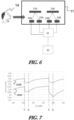
- a measuring enclosure 11 is shown in which, similarly to the figure 1 , a person 14 blows by exhaling his breath.
- a volatile compound in particular volatile organic compound VOC, provided that the layer is sensitive to the volatile compound to be detected, can be introduced into the measuring enclosure 11.
- Light source 23A corresponds to light source 23 of the figure 1 .
- the 25A light detector corresponds to the 25 light detector of the figure 1 and the sensitive reflector element 21A corresponds to the sensitive reflector 21 of the figure 1 .
- the optical detection device 3 further comprises an additional sensitive reflector element 21B.
- This reflector 21B is produced in the same manner and according to the same protocol as the reflector 21A except that 100% TEOS precursor and 0% MTEOS precursor are used.
- the additional sensitive reflector element 21B is illuminated by an additional light source 23B and the reflected light is detected by the additional light detector 25B.
- the assembly between the additional light source 23B, the additional reflector element 23B and the additional light detector 25B is in all respects similar to the assembly of the light source 23A, the reflector element 23A and the light detector 25A and therefore to the assembly as explained with regard to the figure 1 , only the incidence and detection angles can be different.
- the reflector elements are arranged side by side to be illuminated by the same light source.
- the sensitive layer 29 of the reflector 21A has a hydrophobic character while the sensitive layer of the reflector 21B, made from a 100% TEOS sol-gel solution, is hydrophilic.
- the reflector 21B does not absorb (or practically does not absorb) ethanol and that the variation of its refractive index is only a function of the humidity in the atmosphere to be tested.
- the measurement signal at the output of the light detector 25B varies as a function of the humidity level only.
- FIG. 7 shows on a graph as a function of time a measurement signal 250A, for example a voltage, corresponding to the intensity of the light reflected by the reflector element 21A and a measurement signal 250B, for example a voltage, corresponding to the intensity of the light reflected by the reflector element 21A.
- a measurement signal 250A for example a voltage
- a measurement signal 250B for example a voltage
- This average f ( t ) ⁇ t can be correlated via a correlation curve 252 shown in figure 9 to determine the ethanol content of the atmosphere to be tested.
- This calibration curve 252 can be determined experimentally and then stored or recorded in digital form in the processing and calculation unit 31.
- This embodiment can be considered more robust, because it not only allows corrections to take into account the influence of humidity, but also takes into account drifts associated with the outside temperature, the conditions of exposure to expired air and natural aging of the various components forming the optical detection device 3.
Landscapes
- Life Sciences & Earth Sciences (AREA)
- Health & Medical Sciences (AREA)
- Chemical & Material Sciences (AREA)
- Engineering & Computer Science (AREA)
- Physics & Mathematics (AREA)
- Molecular Biology (AREA)
- Immunology (AREA)
- Analytical Chemistry (AREA)
- Biochemistry (AREA)
- General Health & Medical Sciences (AREA)
- General Physics & Mathematics (AREA)
- Pathology (AREA)
- Biomedical Technology (AREA)
- Hematology (AREA)
- Urology & Nephrology (AREA)
- Biophysics (AREA)
- Food Science & Technology (AREA)
- Medicinal Chemistry (AREA)
- Plasma & Fusion (AREA)
- Chemical Kinetics & Catalysis (AREA)
- Microbiology (AREA)
- Biotechnology (AREA)
- Cell Biology (AREA)
- Dispersion Chemistry (AREA)
- Investigating Or Analysing Materials By Optical Means (AREA)
- Investigating Or Analysing Biological Materials (AREA)
- Investigating Or Analysing Materials By The Use Of Chemical Reactions (AREA)
Claims (14)
- Optische Vorrichtung zum Nachweis und zur Quantifizierung von flüchtigen Verbindungen, die Folgendes umfasst:- ein sensitives Reflektorelement (21), dessen Reflexionsgrad in Abhängigkeit vom Ethanolgehalt variiert, der in einer zu prüfenden Atmosphäre enthalten ist, wobei das sensitive Reflektorelement (21) Folgendes umfasst:∘ ein Substrat (27),∘ eine sensitive Schicht (29), die Sol-Gel-Siliciumdioxid mit einer mikroporösen hydrophoben Beschaffenheit umfasst, die eine Dicke von mehr als 250 nm, insbesondere zwischen 400 nm und 1200 nm, eine mittlere Porengröße von weniger als 2 nm und eine Porosität von weniger als 25 % aufweist, wobei die sensitive Schicht (29) dazu vorgesehen ist, mit einer zu prüfenden Atmosphäre, die insbesondere mit Ethanol beladen ist oder nicht, und insbesondere mit dem von einer Person (14) ausgeatmeten Atem in Kontakt gebracht zu werden,- eine monochromatische oder quasi monochromatische Lichtquelle (23), die so angeordnet ist, dass die sensitive Schicht (29) unter einem Einfallswinkel bestrahlt wird,- einen Lichtdetektor (25) zum Messen der vom Reflektorelement (21) unter einem Erfassungswinkel reflektierten Intensität
und- eine Verarbeitungs- und Recheneinheit (31), die konfiguriert ist, um aus der vom Reflektorelement (11) reflektierten Intensität einen Parameter abzuleiten, der einem Blutalkoholspiegel entspricht. - Nachweisvorrichtung nach Anspruch 1, dadurch gekennzeichnet, dass die sensitive Schicht (29) Strukturierungsmittel, insbesondere CTAB, DTAB oder F127, nicht umfasst.
- Nachweisvorrichtung nach einem der Ansprüche 1 bis 2, dadurch gekennzeichnet, dass das Substrat (27) einen Brechungsindex von mehr als 2,5, insbesondere mehr als 3, für eine Wellenlänge zwischen 250 nm und 1500 nm aufweist.
- Nachweisvorrichtung nach einem der Ansprüche 1 bis 3, dadurch gekennzeichnet, dass das Substrat (27) aus einem Halbleitermaterial, insbesondere aus Silicium, besteht.
- Nachweisvorrichtung nach einem der Ansprüche 1 bis 4, dadurch gekennzeichnet, dass der Einfallswinkel und der Erfassungswinkel jeweils zwischen 30° und 75° betragen.
- Nachweisvorrichtung nach einem der Ansprüche 1 bis 5, dadurch gekennzeichnet, dass die Wellenlänge der Lichtquelle (23) monochromatisch ist und mit dem Einfallswinkel so ausgewählt ist, dass sie mit der Position in Bezug auf die Wellenlänge eines Wendepunkts (I1, I2, I3) zwischen zwei Peaks einer konstruktiven und destruktiven Interferenz des Reflexionsspektrums des Reflektorelements (21) zusammenfällt.
- Nachweisvorrichtung nach Anspruch 6, dadurch gekennzeichnet, dass die Wellenlänge der Lichtquelle (23) zwischen 500 nm und 1000 nm liegt.
- Nachweisvorrichtung nach einem der vorhergehenden Ansprüche, dadurch gekennzeichnet, dass die sensitive Schicht (29) einen Brechungsindex zwischen 1,2 und 1,6, insbesondere zwischen 1,3 und 1,4, für eine Wellenlänge zwischen 500 nm und 1000 nm aufweist.
- Nachweisvorrichtung nach einem der Ansprüche 1 bis 8, dadurch gekennzeichnet, dass sie außerdem Folgendes umfasst:- ein zusätzliches sensitives Reflektorelement (21B), dessen Reflexionsgrad in Abhängigkeit vom Feuchtigkeitsgehalt variiert, der in einer zu prüfenden Atmosphäre enthalten ist,- einen zusätzlichen Lichtdetektor (25B) zum Messen der vom zusätzlichen sensitiven Reflektorelement (21B) unter einem Erfassungswinkel reflektierten Intensität,- eine Verarbeitungs- und Recheneinheit (31), die konfiguriert ist, um aus Intensitäten, die einerseits vom Reflektorelement (11) und andererseits vom zusätzlichen sensitiven Reflektorelement (21B) reflektiert werden, einen Parameter abzuleiten, der einem Blutalkoholspiegel entspricht, wobei der Einfluss der Feuchtigkeit in der zu prüfenden Atmosphäre berücksichtigt wird.
- Verfahren zur Herstellung einer optischen Nachweisvorrichtung (3) zum Nachweis und zur Quantifizierung von flüchtigen Verbindungen nach einem der Ansprüche 1 bis 9, dadurch gekennzeichnet, dass- eine sensitive Schicht (29) auf einem Substrat (27) abgeschieden wird, um ein sensitives Reflektorelement (21) zu bilden,- das Reflexionsspektrum des sensitiven Reflektorelements (21) bestimmt wird,- die Wellenlänge der Lichtquelle (23) monochromatisch oder quasimonochromatisch ist und mit dem Einfallswinkel des Lichtstrahls auf das Reflektorelement (21) so ausgewählt wird, dass sie mit der Position in Bezug auf die Wellenlänge eines Wendepunkts (I1, I2, I3) des Reflexionsspektrums des Reflektorelements (21) zusammenfällt.
- Herstellungsverfahren nach Anspruch 10, dadurch gekennzeichnet, dass das Substrat (27) einen Brechungsindex zwischen 1,8 und 4, insbesondere zwischen 2,5 und 3,5, aufweist, die sensitive Schicht (29) eine Dicke von mehr als 250 nm, insbesondere zwischen 400 nm und 1200 nm, aufweist, und einen Brechungsindex zwischen 1,2 und 1,6, insbesondere zwischen 1,3 und 1,4, aufweist, und die Wellenlänge der Lichtquelle (23) zwischen 500 nm und 1000 nm liegt.
- Verfahren nach den Ansprüchen 10 oder 11, dadurch gekennzeichnet, dass das Reflektorelement (21) gemäß dem Verfahren nach Anspruch 10 oder 11 hergestellt wird.
- Optisches Nachweisverfahren zum Nachweis und zur Quantifizierung von flüchtigen Verbindungen in einer zu prüfenden Atmosphäre, dadurch gekennzeichnet, dass es die folgenden Schritte umfasst:- das Messen der Intensität, die von einem sensitiven Reflektorelement (21A) nach einem der Ansprüche 1 bis 8 reflektiert wird, wobei der Reflexionsgrad in Abhängigkeit vom Ethanolgehalt variiert, der in der zu prüfenden Atmosphäre enthalten ist,- das Messen der Intensität, die von einem zusätzlichen sensitiven Reflektorelement (21B) nach Anspruch 9 reflektiert wird, wobei der Reflexionsgrad in Abhängigkeit vom Feuchtigkeitsgehalt variiert, der in der zu prüfenden Atmosphäre enthalten ist,- in einem interessierenden vorbestimmten Zeitbereich (Δt), für den im Fall des Fehlens von Ethanol die zeitliche Ableitung für die beiden gemessenen Intensitäten gleich ist, das Bestimmen der Differenz der zeitlichen Ableitung der gemessenen beiden Intensitäten, um eine Korrelation mit einer Kalibrierungskurve (252) durchzuführen, um das Ethanol zu quantifizieren, das in der zu prüfenden Atmosphäre enthalten ist.
- Optisches Nachweisverfahren zum Nachweis und zur Quantifizierung von flüchtigen Verbindungen in einer zu prüfenden Atmosphäre nach Anspruch 13, dadurch gekennzeichnet, dass die Wellenlänge der Lichtquelle (23) so ausgewählt ist, dass sie mit der Position in Bezug auf die Wellenlänge eines Wendepunkts (I1, I2, I3) zwischen zwei Peaks einer konstruktiven und destruktiven Interferenz des Reflexionsspektrums des sensitiven Reflektorelements (21A) zusammenfällt.
Applications Claiming Priority (2)
| Application Number | Priority Date | Filing Date | Title |
|---|---|---|---|
| FR1754533A FR3066603B1 (fr) | 2017-05-22 | 2017-05-22 | Dispositif optique de detection et de quantification de composes volatils |
| PCT/EP2018/062605 WO2018215247A1 (fr) | 2017-05-22 | 2018-05-15 | Dispositif optique de détection et de quantification de composés volatils |
Publications (2)
| Publication Number | Publication Date |
|---|---|
| EP3631423A1 EP3631423A1 (de) | 2020-04-08 |
| EP3631423B1 true EP3631423B1 (de) | 2024-08-14 |
Family
ID=59381514
Family Applications (1)
| Application Number | Title | Priority Date | Filing Date |
|---|---|---|---|
| EP18727711.6A Active EP3631423B1 (de) | 2017-05-22 | 2018-05-15 | Optische vorrichtung zur erfassung und quantifizierung von flüchtigen verbindungen |
Country Status (8)
| Country | Link |
|---|---|
| US (1) | US20200200778A1 (de) |
| EP (1) | EP3631423B1 (de) |
| JP (1) | JP7165682B2 (de) |
| CN (1) | CN110832306B (de) |
| AU (2) | AU2018274521A1 (de) |
| CA (1) | CA3062301A1 (de) |
| FR (1) | FR3066603B1 (de) |
| WO (1) | WO2018215247A1 (de) |
Family Cites Families (11)
| Publication number | Priority date | Publication date | Assignee | Title |
|---|---|---|---|---|
| US7037554B2 (en) * | 2003-06-30 | 2006-05-02 | Mississippi State University | Moisture sensor based on evanescent wave light scattering by porous sol-gel silica coating |
| US20060154044A1 (en) * | 2005-01-07 | 2006-07-13 | Pentax Corporation | Anti-reflection coating and optical element having such anti-reflection coating for image sensors |
| US8293340B2 (en) * | 2005-12-21 | 2012-10-23 | 3M Innovative Properties Company | Plasma deposited microporous analyte detection layer |
| KR101821936B1 (ko) * | 2008-12-23 | 2018-01-24 | 쓰리엠 이노베이티브 프로퍼티즈 컴파니 | 미세다공성 유기실리케이트 재료를 갖는 유기 화학적 센서 |
| GB0919742D0 (en) * | 2009-11-11 | 2009-12-30 | Millipore Corp | Optical sensor |
| JP2012122755A (ja) * | 2010-12-06 | 2012-06-28 | Toyota Central R&D Labs Inc | 光センサ装置 |
| US9429537B2 (en) * | 2011-04-13 | 2016-08-30 | 3M Innovative Properties Company | Method of detecting volatile organic compounds |
| JP6038950B2 (ja) * | 2011-12-13 | 2016-12-07 | スリーエム イノベイティブ プロパティズ カンパニー | 気体媒質内の未知の有機化合物の同定及び定量測定方法 |
| WO2014078512A1 (en) * | 2012-11-14 | 2014-05-22 | 3M Innovative Properties Company | Adjustable colorimetric moisture indicators |
| GB201321245D0 (en) * | 2013-12-02 | 2014-01-15 | Univ Ireland Dublin | Gas sensor |
| GB2525854B (en) * | 2014-05-02 | 2019-08-07 | Sensorhut Ltd | Sensing methods and apparatus |
-
2017
- 2017-05-22 FR FR1754533A patent/FR3066603B1/fr active Active
-
2018
- 2018-05-15 JP JP2019564483A patent/JP7165682B2/ja active Active
- 2018-05-15 WO PCT/EP2018/062605 patent/WO2018215247A1/fr not_active Ceased
- 2018-05-15 US US16/615,486 patent/US20200200778A1/en not_active Abandoned
- 2018-05-15 EP EP18727711.6A patent/EP3631423B1/de active Active
- 2018-05-15 CN CN201880033485.0A patent/CN110832306B/zh active Active
- 2018-05-15 CA CA3062301A patent/CA3062301A1/fr active Pending
- 2018-05-15 AU AU2018274521A patent/AU2018274521A1/en not_active Abandoned
-
2024
- 2024-02-02 AU AU2024200667A patent/AU2024200667A1/en not_active Abandoned
Also Published As
| Publication number | Publication date |
|---|---|
| WO2018215247A1 (fr) | 2018-11-29 |
| AU2018274521A1 (en) | 2019-12-12 |
| CN110832306A (zh) | 2020-02-21 |
| FR3066603B1 (fr) | 2019-07-05 |
| EP3631423A1 (de) | 2020-04-08 |
| US20200200778A1 (en) | 2020-06-25 |
| JP7165682B2 (ja) | 2022-11-04 |
| FR3066603A1 (fr) | 2018-11-23 |
| CN110832306B (zh) | 2023-07-04 |
| AU2024200667A1 (en) | 2024-02-22 |
| JP2020521135A (ja) | 2020-07-16 |
| CA3062301A1 (fr) | 2018-11-29 |
Similar Documents
| Publication | Publication Date | Title |
|---|---|---|
| Russell et al. | Optical sensor for the determination of moisture | |
| JP5462892B2 (ja) | 全反射減衰型光学プローブおよびそれを用いた水溶液分光測定装置 | |
| EP3589946A1 (de) | Verfahren zur kalibrierung einer elektronischen nase | |
| Zhan et al. | Enhanced-performance relative humidity sensor based on MOF-801 photonic crystals | |
| US8711356B2 (en) | Gas sensor with a porous layer that detectably affects a surface lattice resonant condition of a nanoparticle array | |
| CN101535798A (zh) | 甲醛检测体、甲醛检测装置、甲醛检测方法以及甲醛检测试剂 | |
| EP2423668B1 (de) | Vorrichtung und Verfahren zur Detektion eines Analyten in einer gasförmigen Probe | |
| JP2008224240A (ja) | 全反射減衰型光学プローブおよびそれを用いた水溶液分光測定装置 | |
| Sweetman et al. | Chemically patterned porous silicon photonic crystals towards internally referenced organic vapour sensors | |
| JP4958220B2 (ja) | 全反射減衰型光学プローブおよびそれを用いた水溶液分光測定装置 | |
| Rahmat et al. | Development of a novel ozone gas sensor based on sol–gel fabricated photonic crystal | |
| FR3066603B1 (fr) | Dispositif optique de detection et de quantification de composes volatils | |
| US20090066957A1 (en) | Method and Apparatus for Sensing a Target Substance by Analysing Time Series of Said Target Substance | |
| EP3884266B1 (de) | Optische vorrichtung zur detektion von flüchtigen verbindungen und zugehöriges verfahren zur detektion und quantifizierung von flüchtigen verbindungen | |
| EP3234551B1 (de) | Retroreflektoren für retroflexion und umgebungserfassung | |
| WO2011058502A2 (en) | Gas sensing device having a photonic structure operating by means of bloch surface waves and corresponding manufacturing process | |
| Vasiliev et al. | Photonic nano-structures for water quality monitoring | |
| Paliwal et al. | Exploitation of polypyrrole nanostructured thin films for detecting poisonous lead metal ions using surface plasmon resonance technique | |
| Saarinen et al. | Simulation on wavelength-dependent complex refractive index of liquids obtained by phase retrieval from reflectance dip due to surface plasmon resonance | |
| Seven et al. | Optical detection of ethanol vapor using a porous silicon Bragg reflector in the SWIR region | |
| Sohn | Fabrication and characterization of optically encoded porous silicon smart particles | |
| Javahiraly et al. | On a Sensitive Optical Sensor for Hydrogen Leak Detection. | |
| EP4198489A1 (de) | Vorrichtung zum nachweis flüchtiger siloxanmoleküle | |
| WO2015082836A1 (fr) | Procédé de mesure de la température d'un verre | |
| Kobayashi et al. | Humidity adsorption and surface plasmon excitation of poly (vinyl alcohol) films with fluorescent microspheres |
Legal Events
| Date | Code | Title | Description |
|---|---|---|---|
| STAA | Information on the status of an ep patent application or granted ep patent |
Free format text: STATUS: UNKNOWN |
|
| STAA | Information on the status of an ep patent application or granted ep patent |
Free format text: STATUS: THE INTERNATIONAL PUBLICATION HAS BEEN MADE |
|
| PUAI | Public reference made under article 153(3) epc to a published international application that has entered the european phase |
Free format text: ORIGINAL CODE: 0009012 |
|
| STAA | Information on the status of an ep patent application or granted ep patent |
Free format text: STATUS: REQUEST FOR EXAMINATION WAS MADE |
|
| 17P | Request for examination filed |
Effective date: 20191112 |
|
| AK | Designated contracting states |
Kind code of ref document: A1 Designated state(s): AL AT BE BG CH CY CZ DE DK EE ES FI FR GB GR HR HU IE IS IT LI LT LU LV MC MK MT NL NO PL PT RO RS SE SI SK SM TR |
|
| AX | Request for extension of the european patent |
Extension state: BA ME |
|
| DAV | Request for validation of the european patent (deleted) | ||
| DAX | Request for extension of the european patent (deleted) | ||
| STAA | Information on the status of an ep patent application or granted ep patent |
Free format text: STATUS: EXAMINATION IS IN PROGRESS |
|
| 17Q | First examination report despatched |
Effective date: 20220525 |
|
| GRAP | Despatch of communication of intention to grant a patent |
Free format text: ORIGINAL CODE: EPIDOSNIGR1 |
|
| STAA | Information on the status of an ep patent application or granted ep patent |
Free format text: STATUS: GRANT OF PATENT IS INTENDED |
|
| RIC1 | Information provided on ipc code assigned before grant |
Ipc: G01N 33/497 20060101ALI20240327BHEP Ipc: G01N 31/22 20060101ALI20240327BHEP Ipc: G01N 21/77 20060101AFI20240327BHEP |
|
| INTG | Intention to grant announced |
Effective date: 20240424 |
|
| GRAS | Grant fee paid |
Free format text: ORIGINAL CODE: EPIDOSNIGR3 |
|
| GRAA | (expected) grant |
Free format text: ORIGINAL CODE: 0009210 |
|
| STAA | Information on the status of an ep patent application or granted ep patent |
Free format text: STATUS: THE PATENT HAS BEEN GRANTED |
|
| AK | Designated contracting states |
Kind code of ref document: B1 Designated state(s): AL AT BE BG CH CY CZ DE DK EE ES FI FR GB GR HR HU IE IS IT LI LT LU LV MC MK MT NL NO PL PT RO RS SE SI SK SM TR |
|
| REG | Reference to a national code |
Ref country code: GB Ref legal event code: FG4D Free format text: NOT ENGLISH |
|
| REG | Reference to a national code |
Ref country code: CH Ref legal event code: EP |
|
| REG | Reference to a national code |
Ref country code: DE Ref legal event code: R096 Ref document number: 602018073057 Country of ref document: DE |
|
| REG | Reference to a national code |
Ref country code: IE Ref legal event code: FG4D Free format text: LANGUAGE OF EP DOCUMENT: FRENCH |
|
| REG | Reference to a national code |
Ref country code: LT Ref legal event code: MG9D |
|
| REG | Reference to a national code |
Ref country code: NL Ref legal event code: MP Effective date: 20240814 |
|
| PG25 | Lapsed in a contracting state [announced via postgrant information from national office to epo] |
Ref country code: NO Free format text: LAPSE BECAUSE OF FAILURE TO SUBMIT A TRANSLATION OF THE DESCRIPTION OR TO PAY THE FEE WITHIN THE PRESCRIBED TIME-LIMIT Effective date: 20241114 |
|
| REG | Reference to a national code |
Ref country code: AT Ref legal event code: MK05 Ref document number: 1713710 Country of ref document: AT Kind code of ref document: T Effective date: 20240814 |
|
| PG25 | Lapsed in a contracting state [announced via postgrant information from national office to epo] |
Ref country code: PL Free format text: LAPSE BECAUSE OF FAILURE TO SUBMIT A TRANSLATION OF THE DESCRIPTION OR TO PAY THE FEE WITHIN THE PRESCRIBED TIME-LIMIT Effective date: 20240814 Ref country code: NL Free format text: LAPSE BECAUSE OF FAILURE TO SUBMIT A TRANSLATION OF THE DESCRIPTION OR TO PAY THE FEE WITHIN THE PRESCRIBED TIME-LIMIT Effective date: 20240814 Ref country code: GR Free format text: LAPSE BECAUSE OF FAILURE TO SUBMIT A TRANSLATION OF THE DESCRIPTION OR TO PAY THE FEE WITHIN THE PRESCRIBED TIME-LIMIT Effective date: 20241115 Ref country code: FI Free format text: LAPSE BECAUSE OF FAILURE TO SUBMIT A TRANSLATION OF THE DESCRIPTION OR TO PAY THE FEE WITHIN THE PRESCRIBED TIME-LIMIT Effective date: 20240814 Ref country code: PT Free format text: LAPSE BECAUSE OF FAILURE TO SUBMIT A TRANSLATION OF THE DESCRIPTION OR TO PAY THE FEE WITHIN THE PRESCRIBED TIME-LIMIT Effective date: 20241216 |
|
| PG25 | Lapsed in a contracting state [announced via postgrant information from national office to epo] |
Ref country code: BG Free format text: LAPSE BECAUSE OF FAILURE TO SUBMIT A TRANSLATION OF THE DESCRIPTION OR TO PAY THE FEE WITHIN THE PRESCRIBED TIME-LIMIT Effective date: 20240814 |
|
| PG25 | Lapsed in a contracting state [announced via postgrant information from national office to epo] |
Ref country code: LV Free format text: LAPSE BECAUSE OF FAILURE TO SUBMIT A TRANSLATION OF THE DESCRIPTION OR TO PAY THE FEE WITHIN THE PRESCRIBED TIME-LIMIT Effective date: 20240814 |
|
| PG25 | Lapsed in a contracting state [announced via postgrant information from national office to epo] |
Ref country code: AT Free format text: LAPSE BECAUSE OF FAILURE TO SUBMIT A TRANSLATION OF THE DESCRIPTION OR TO PAY THE FEE WITHIN THE PRESCRIBED TIME-LIMIT Effective date: 20240814 Ref country code: IS Free format text: LAPSE BECAUSE OF FAILURE TO SUBMIT A TRANSLATION OF THE DESCRIPTION OR TO PAY THE FEE WITHIN THE PRESCRIBED TIME-LIMIT Effective date: 20241214 |
|
| PG25 | Lapsed in a contracting state [announced via postgrant information from national office to epo] |
Ref country code: HR Free format text: LAPSE BECAUSE OF FAILURE TO SUBMIT A TRANSLATION OF THE DESCRIPTION OR TO PAY THE FEE WITHIN THE PRESCRIBED TIME-LIMIT Effective date: 20240814 |
|
| PG25 | Lapsed in a contracting state [announced via postgrant information from national office to epo] |
Ref country code: RS Free format text: LAPSE BECAUSE OF FAILURE TO SUBMIT A TRANSLATION OF THE DESCRIPTION OR TO PAY THE FEE WITHIN THE PRESCRIBED TIME-LIMIT Effective date: 20241114 Ref country code: ES Free format text: LAPSE BECAUSE OF FAILURE TO SUBMIT A TRANSLATION OF THE DESCRIPTION OR TO PAY THE FEE WITHIN THE PRESCRIBED TIME-LIMIT Effective date: 20240814 |
|
| PG25 | Lapsed in a contracting state [announced via postgrant information from national office to epo] |
Ref country code: RS Free format text: LAPSE BECAUSE OF FAILURE TO SUBMIT A TRANSLATION OF THE DESCRIPTION OR TO PAY THE FEE WITHIN THE PRESCRIBED TIME-LIMIT Effective date: 20241114 Ref country code: PT Free format text: LAPSE BECAUSE OF FAILURE TO SUBMIT A TRANSLATION OF THE DESCRIPTION OR TO PAY THE FEE WITHIN THE PRESCRIBED TIME-LIMIT Effective date: 20241216 Ref country code: PL Free format text: LAPSE BECAUSE OF FAILURE TO SUBMIT A TRANSLATION OF THE DESCRIPTION OR TO PAY THE FEE WITHIN THE PRESCRIBED TIME-LIMIT Effective date: 20240814 Ref country code: NO Free format text: LAPSE BECAUSE OF FAILURE TO SUBMIT A TRANSLATION OF THE DESCRIPTION OR TO PAY THE FEE WITHIN THE PRESCRIBED TIME-LIMIT Effective date: 20241114 Ref country code: NL Free format text: LAPSE BECAUSE OF FAILURE TO SUBMIT A TRANSLATION OF THE DESCRIPTION OR TO PAY THE FEE WITHIN THE PRESCRIBED TIME-LIMIT Effective date: 20240814 Ref country code: LV Free format text: LAPSE BECAUSE OF FAILURE TO SUBMIT A TRANSLATION OF THE DESCRIPTION OR TO PAY THE FEE WITHIN THE PRESCRIBED TIME-LIMIT Effective date: 20240814 Ref country code: IS Free format text: LAPSE BECAUSE OF FAILURE TO SUBMIT A TRANSLATION OF THE DESCRIPTION OR TO PAY THE FEE WITHIN THE PRESCRIBED TIME-LIMIT Effective date: 20241214 Ref country code: HR Free format text: LAPSE BECAUSE OF FAILURE TO SUBMIT A TRANSLATION OF THE DESCRIPTION OR TO PAY THE FEE WITHIN THE PRESCRIBED TIME-LIMIT Effective date: 20240814 Ref country code: GR Free format text: LAPSE BECAUSE OF FAILURE TO SUBMIT A TRANSLATION OF THE DESCRIPTION OR TO PAY THE FEE WITHIN THE PRESCRIBED TIME-LIMIT Effective date: 20241115 Ref country code: FI Free format text: LAPSE BECAUSE OF FAILURE TO SUBMIT A TRANSLATION OF THE DESCRIPTION OR TO PAY THE FEE WITHIN THE PRESCRIBED TIME-LIMIT Effective date: 20240814 Ref country code: ES Free format text: LAPSE BECAUSE OF FAILURE TO SUBMIT A TRANSLATION OF THE DESCRIPTION OR TO PAY THE FEE WITHIN THE PRESCRIBED TIME-LIMIT Effective date: 20240814 Ref country code: BG Free format text: LAPSE BECAUSE OF FAILURE TO SUBMIT A TRANSLATION OF THE DESCRIPTION OR TO PAY THE FEE WITHIN THE PRESCRIBED TIME-LIMIT Effective date: 20240814 Ref country code: AT Free format text: LAPSE BECAUSE OF FAILURE TO SUBMIT A TRANSLATION OF THE DESCRIPTION OR TO PAY THE FEE WITHIN THE PRESCRIBED TIME-LIMIT Effective date: 20240814 |
|
| PG25 | Lapsed in a contracting state [announced via postgrant information from national office to epo] |
Ref country code: SM Free format text: LAPSE BECAUSE OF FAILURE TO SUBMIT A TRANSLATION OF THE DESCRIPTION OR TO PAY THE FEE WITHIN THE PRESCRIBED TIME-LIMIT Effective date: 20240814 Ref country code: RO Free format text: LAPSE BECAUSE OF FAILURE TO SUBMIT A TRANSLATION OF THE DESCRIPTION OR TO PAY THE FEE WITHIN THE PRESCRIBED TIME-LIMIT Effective date: 20240814 Ref country code: DK Free format text: LAPSE BECAUSE OF FAILURE TO SUBMIT A TRANSLATION OF THE DESCRIPTION OR TO PAY THE FEE WITHIN THE PRESCRIBED TIME-LIMIT Effective date: 20240814 |
|
| PG25 | Lapsed in a contracting state [announced via postgrant information from national office to epo] |
Ref country code: EE Free format text: LAPSE BECAUSE OF FAILURE TO SUBMIT A TRANSLATION OF THE DESCRIPTION OR TO PAY THE FEE WITHIN THE PRESCRIBED TIME-LIMIT Effective date: 20240814 |
|
| PG25 | Lapsed in a contracting state [announced via postgrant information from national office to epo] |
Ref country code: CZ Free format text: LAPSE BECAUSE OF FAILURE TO SUBMIT A TRANSLATION OF THE DESCRIPTION OR TO PAY THE FEE WITHIN THE PRESCRIBED TIME-LIMIT Effective date: 20240814 |
|
| PG25 | Lapsed in a contracting state [announced via postgrant information from national office to epo] |
Ref country code: SK Free format text: LAPSE BECAUSE OF FAILURE TO SUBMIT A TRANSLATION OF THE DESCRIPTION OR TO PAY THE FEE WITHIN THE PRESCRIBED TIME-LIMIT Effective date: 20240814 Ref country code: IT Free format text: LAPSE BECAUSE OF FAILURE TO SUBMIT A TRANSLATION OF THE DESCRIPTION OR TO PAY THE FEE WITHIN THE PRESCRIBED TIME-LIMIT Effective date: 20240814 |
|
| REG | Reference to a national code |
Ref country code: DE Ref legal event code: R097 Ref document number: 602018073057 Country of ref document: DE |
|
| PLBE | No opposition filed within time limit |
Free format text: ORIGINAL CODE: 0009261 |
|
| STAA | Information on the status of an ep patent application or granted ep patent |
Free format text: STATUS: NO OPPOSITION FILED WITHIN TIME LIMIT |
|
| 26N | No opposition filed |
Effective date: 20250515 |
|
| PG25 | Lapsed in a contracting state [announced via postgrant information from national office to epo] |
Ref country code: SE Free format text: LAPSE BECAUSE OF FAILURE TO SUBMIT A TRANSLATION OF THE DESCRIPTION OR TO PAY THE FEE WITHIN THE PRESCRIBED TIME-LIMIT Effective date: 20240814 |
|
| REG | Reference to a national code |
Ref country code: CH Ref legal event code: H13 Free format text: ST27 STATUS EVENT CODE: U-0-0-H10-H13 (AS PROVIDED BY THE NATIONAL OFFICE) Effective date: 20251223 |
|
| PG25 | Lapsed in a contracting state [announced via postgrant information from national office to epo] |
Ref country code: LU Free format text: LAPSE BECAUSE OF NON-PAYMENT OF DUE FEES Effective date: 20250515 |
|
| PG25 | Lapsed in a contracting state [announced via postgrant information from national office to epo] |
Ref country code: CH Free format text: LAPSE BECAUSE OF NON-PAYMENT OF DUE FEES Effective date: 20250531 |
|
| REG | Reference to a national code |
Ref country code: BE Ref legal event code: MM Effective date: 20250531 |
|
| PG25 | Lapsed in a contracting state [announced via postgrant information from national office to epo] |
Ref country code: MC Free format text: LAPSE BECAUSE OF FAILURE TO SUBMIT A TRANSLATION OF THE DESCRIPTION OR TO PAY THE FEE WITHIN THE PRESCRIBED TIME-LIMIT Effective date: 20240814 |
|
| PG25 | Lapsed in a contracting state [announced via postgrant information from national office to epo] |
Ref country code: IE Free format text: LAPSE BECAUSE OF NON-PAYMENT OF DUE FEES Effective date: 20250515 |
|
| PG25 | Lapsed in a contracting state [announced via postgrant information from national office to epo] |
Ref country code: BE Free format text: LAPSE BECAUSE OF NON-PAYMENT OF DUE FEES Effective date: 20250531 |
|
| PG25 | Lapsed in a contracting state [announced via postgrant information from national office to epo] |
Ref country code: LT Free format text: LAPSE BECAUSE OF FAILURE TO SUBMIT A TRANSLATION OF THE DESCRIPTION OR TO PAY THE FEE WITHIN THE PRESCRIBED TIME-LIMIT Effective date: 20240814 |
|
| PGFP | Annual fee paid to national office [announced via postgrant information from national office to epo] |
Ref country code: GB Payment date: 20260527 Year of fee payment: 9 |
|
| PGFP | Annual fee paid to national office [announced via postgrant information from national office to epo] |
Ref country code: DE Payment date: 20260602 Year of fee payment: 9 |
|
| PGFP | Annual fee paid to national office [announced via postgrant information from national office to epo] |
Ref country code: FR Payment date: 20260528 Year of fee payment: 9 |
|
| PG25 | Lapsed in a contracting state [announced via postgrant information from national office to epo] |
Ref country code: CY Free format text: LAPSE BECAUSE OF FAILURE TO SUBMIT A TRANSLATION OF THE DESCRIPTION OR TO PAY THE FEE WITHIN THE PRESCRIBED TIME-LIMIT Effective date: 20240814 |