EP3633255B1 - Schraubverbindung für stahlröhre - Google Patents
Schraubverbindung für stahlröhre Download PDFInfo
- Publication number
- EP3633255B1 EP3633255B1 EP18806267.3A EP18806267A EP3633255B1 EP 3633255 B1 EP3633255 B1 EP 3633255B1 EP 18806267 A EP18806267 A EP 18806267A EP 3633255 B1 EP3633255 B1 EP 3633255B1
- Authority
- EP
- European Patent Office
- Prior art keywords
- pin
- box
- sealing surface
- nose
- seal
- Prior art date
- Legal status (The legal status is an assumption and is not a legal conclusion. Google has not performed a legal analysis and makes no representation as to the accuracy of the status listed.)
- Active
Links
Images



Classifications
-
- F—MECHANICAL ENGINEERING; LIGHTING; HEATING; WEAPONS; BLASTING
- F16—ENGINEERING ELEMENTS AND UNITS; GENERAL MEASURES FOR PRODUCING AND MAINTAINING EFFECTIVE FUNCTIONING OF MACHINES OR INSTALLATIONS; THERMAL INSULATION IN GENERAL
- F16L—PIPES; JOINTS OR FITTINGS FOR PIPES; SUPPORTS FOR PIPES, CABLES OR PROTECTIVE TUBING; MEANS FOR THERMAL INSULATION IN GENERAL
- F16L15/00—Screw-threaded joints; Forms of screw-threads for such joints
- F16L15/001—Screw-threaded joints; Forms of screw-threads for such joints with conical threads
- F16L15/004—Screw-threaded joints; Forms of screw-threads for such joints with conical threads with axial sealings having at least one plastically deformable sealing surface
-
- E—FIXED CONSTRUCTIONS
- E21—EARTH OR ROCK DRILLING; MINING
- E21B—EARTH OR ROCK DRILLING; OBTAINING OIL, GAS, WATER, SOLUBLE OR MELTABLE MATERIALS OR A SLURRY OF MINERALS FROM WELLS
- E21B17/00—Drilling rods or pipes; Flexible drill strings; Kellies; Drill collars; Sucker rods; Cables; Casings; Tubings
- E21B17/02—Couplings; joints
- E21B17/04—Couplings; joints between rod or the like and bit or between rod and rod or the like
- E21B17/042—Threaded
-
- F—MECHANICAL ENGINEERING; LIGHTING; HEATING; WEAPONS; BLASTING
- F16—ENGINEERING ELEMENTS AND UNITS; GENERAL MEASURES FOR PRODUCING AND MAINTAINING EFFECTIVE FUNCTIONING OF MACHINES OR INSTALLATIONS; THERMAL INSULATION IN GENERAL
- F16L—PIPES; JOINTS OR FITTINGS FOR PIPES; SUPPORTS FOR PIPES, CABLES OR PROTECTIVE TUBING; MEANS FOR THERMAL INSULATION IN GENERAL
- F16L15/00—Screw-threaded joints; Forms of screw-threads for such joints
- F16L15/04—Screw-threaded joints; Forms of screw-threads for such joints with additional sealings
-
- F—MECHANICAL ENGINEERING; LIGHTING; HEATING; WEAPONS; BLASTING
- F16—ENGINEERING ELEMENTS AND UNITS; GENERAL MEASURES FOR PRODUCING AND MAINTAINING EFFECTIVE FUNCTIONING OF MACHINES OR INSTALLATIONS; THERMAL INSULATION IN GENERAL
- F16L—PIPES; JOINTS OR FITTINGS FOR PIPES; SUPPORTS FOR PIPES, CABLES OR PROTECTIVE TUBING; MEANS FOR THERMAL INSULATION IN GENERAL
- F16L15/00—Screw-threaded joints; Forms of screw-threads for such joints
- F16L15/001—Screw-threaded joints; Forms of screw-threads for such joints with conical threads
- F16L15/003—Screw-threaded joints; Forms of screw-threads for such joints with conical threads with sealing rings
Definitions
- the present disclosure relates to a threaded connection for steel pipes.
- OCTGs Steel pipes called oil country tubular goods
- oil wells for example, for prospecting or producing oil or natural gas in oil wells or natural-gas wells (hereinafter collectively referred to as "oil wells” or the like), developing non-conventional resources such as oil sand or shale gas, retrieving or storing carbon dioxide (Carbon dioxide Capture and Storage (CCS)), geothermal power generation, or in hot springs.
- CCS Carbon dioxide Capture and Storage
- a threaded connection is used to connect OCTGs.
- Such OCTG threaded connections are generally categorized as coupling type and integral type.
- a coupling-type connection connects a pair of pipes, one of which is an OCTG and the other one is a coupling.
- a male thread is provided on the outer periphery of each of the ends of the OCTG, while a female thread is provided on the inner periphery of each of the ends of the coupling. Then, the male thread of the OCTG is screwed into the female thread of the coupling such that they are made up and connected.
- An integral-type connection connects a pair of pipes that are both OCTGs, and does not use a separate coupling.
- a male thread is provided on the outer periphery of one end of each OCTG, while a female thread is provided on the inner periphery of the other end. Then, the male thread of one OCTG is screwed into the female thread of the other OCTG such that they are made up and connected.
- a connection portion of a pipe end on which a male thread is provided includes an element to be inserted into a female thread, and thus is usually referred to as "pin”.
- a connection portion of a pipe end on which a female thread is provided includes an element for receiving a male thread, and thus is referred to as "box”.
- a pin and a box constitute ends of pipes and are thus tubular in shape.
- a threaded connection is required to have good sealing performance against the pressure of fluid from the inside (hereinafter referred to as "internal pressure") and the pressure of fluid from the outside (hereinafter referred to as “external pressure”).
- the threaded connection is provided with a seal using metal-to-metal contact.
- the seal is composed of a pin sealing surface and a box sealing surface that has a diameter slightly smaller than the diameter of the pin sealing surface. The difference between the diameter of the pin sealing surface and the diameter of the box sealing surface will be referred to as amount of seal interference.
- Each of the sealing surfaces tries to deform to their original diameters and thus produces an elastic recovery force, which causes the sealing surfaces to tightly contact with each other along the entire circumference, thereby providing sealing performance.
- the larger the amount of seal interference the higher the contact pressure on the sealing surfaces, thus increasing sealing performance.
- the pin includes a pin shoulder surface, a pin sealing surface and a male thread in this order, starting at the tip and going toward the OCTG body.
- the box includes a box shoulder surface, a box sealing surface and a female thread.
- the pin is provided with a nose.
- the nose is located between the pin shoulder surface and pin sealing surface. The outer periphery of the nose is not in contact with the box when the connection has been made up. The nose increases the stiffness of portions near the pin sealing surface.
- the pin sealing surface is prevented from being deformed to reduce its diameter, which prevents the real amount of seal interference from decreasing, thereby improving the sealing performance against the external pressure.
- Patent Document 2 also discloses a threaded connection having a nose construction.
- Patent Document 2 teaches that, where L is the length of the pin lip and x is the distance between the front end of the male thread and seal position, x/L is suitably 0.2 to 0.8.
- the seal position is the position on the outer peripheral surface of the pin lip that first contacts the box sealing surface during make-up of the connections.
- An object of the present disclosure is to provide a threaded connection for steel pipes having improved sealing performance.
- a threaded connection for steel pipes includes a tubular pin and a tubular box.
- the pin is provided adjacent to a steel pipe body.
- the pin is inserted into the box such that the box and the pin are made up.
- the pin includes a nose, a pin shoulder surface, a male thread, and a pin sealing surface.
- the nose provides a tip portion of the pin.
- the pin shoulder surface is provided on a tip surface of the nose.
- the male thread is provided on an outer periphery of the pin and located closer to the steel pipe body than the nose.
- the pin sealing surface is provided on the outer periphery of the pin and located between the nose and the male thread.
- the box includes a box shoulder surface, a female thread, and a box sealing surface.
- the box shoulder surface is provided to correspond to the pin shoulder surface and located in an interior region of the box.
- the box shoulder surface is in contact with the pin shoulder surface when the connection has been made up.
- the female thread is provided to correspond to the male thread and located on an inner periphery of the box.
- the box sealing surface is provided to correspond to the pin sealing surface and located on the inner periphery of the box.
- the box sealing surface is in contact with the pin sealing surface when the connection has been made up.
- the pin sealing surface is formed by a taper surface.
- An outer peripheral surface of the nose is formed by a taper surface having a taper angle that is smaller than a taper angle of the pin sealing surface.
- connection When the connection has been made up, an outer periphery of the nose faces the inner periphery of the box with a clearance present therebetween.
- the threaded connection satisfies 0.4 ⁇ x/L ⁇ 0.55.
- x is a distance between a seal position and the end of the male thread adjacent to the pin sealing surface as measured in the pipe-axis direction, the seal position being a position of the pin sealing surface that first contacts the inner periphery of the box during make-up
- L is a distance between the tip of the pin and the end of the male thread adjacent to the pin sealing surface as measured in the pipe-axis direction.
- the present disclosure provides improved sealing performance to a threaded connection for steel pipes.
- the nose increases the stiffness of the seal. As such, even when an external pressure is applied to the threaded connection, the seal is unlikely to be deformed to reduce its diameter, thereby preventing the real amount of seal interference from decreasing. This provides good external-pressure sealing performance.
- the present inventors found out that a change in the value of x/L works to both improve and worsen external-pressure sealing performance. This suggests that the ultimate sealing performance depends on the balance between the magnitude of the influence of the value of x/L to improve sealing performance and the magnitude of the influence of the value of x/L to worsen sealing performance. A specific explanation of this will be given below with reference to FIG. 1 .
- FIG. 1 is a graph schematically illustrating the relationship between the value of x/L and external-pressure sealing performance.
- Lines a1 and a2 in FIG. 1 each indicate the relationship between the value of x/L and external-pressure sealing performance, where factors responsible for improving external-pressure sealing performance and those responsible for worsening external-pressure sealing performance are treated separately.
- Line A in FIG. 1 is the sum of lines a1 and a2, and indicates the relationship between the value of x/L and the ultimate external-pressure sealing performance.
- a change in the value of x/L affects the stiffness of the seal, the easiness with which the seal can be deformed to reduce its diameter, and the decrease in the real amount of interference of the seal.
- the ultimate sealing performance is determined by summing the influence of x/L upon the stiffness of the seal and the easiness with which the seal can be deformed to reduce its diameter (line a1) and the influence of x/L on the decrease in the real amount of interference of the seal (line a2), as indicated by line A in FIG. 1 .
- the present inventors anticipated that there should be the optimum range of x/L for producing good ultimate sealing performance.
- the present inventors did research to find the optimum range of x/L.
- the present inventors found that, if x/L is 0.4 or larger, the real amount of interference of the seal is hardly reduced by the interference between the threads, thereby providing good sealing performance, especially against the internal pressure.
- the present inventors found that the external-pressure sealing performance tends to decrease as x/L increases.
- the present inventors found that, if x/L is 0.55 or smaller, the effect of the interference between the threads, of reduction of the decrease in the real amount of interference at the seal, is larger than the adverse effect of the decrease in the length of the nose, of reduction of the stiffness of the seal, thereby improving sealing performance, especially against the external pressure.
- the present inventors made the threaded connections for steel pipes according to the embodiments.
- a threaded connection for steel pipes includes a tubular pin and a tubular box.
- the pin is provided adjacent to a steel pipe body.
- the pin is inserted into the box such that the box and the pin are made up.
- the pin includes a nose, a pin shoulder surface, a male thread, and a pin sealing surface.
- the nose provides a tip portion of the pin.
- the pin shoulder surface is provided on a tip surface of the nose.
- the male thread is provided on an outer periphery of the pin and located closer to the steel pipe body than the nose is.
- the pin sealing surface is provided on the outer periphery of the pin and located between the nose and the male thread.
- the box includes a box shoulder surface, a female thread, and a box sealing surface.
- the box shoulder surface is provided to correspond to the pin shoulder surface and located in an interior region of the box.
- the box shoulder surface is in contact with the pin shoulder surface when the connection has been made up.
- the female thread is provided to correspond to the male thread and located on an inner periphery of the box.
- the box sealing surface is provided to correspond to the pin sealing surface and located on the inner periphery of the box.
- the box sealing surface is in contact with the pin sealing surface when the connection has been made up.
- the pin sealing surface is formed by a taper surface.
- An outer peripheral surface of the nose is formed by a taper surface having a taper angle that is smaller than a taper angle of the pin sealing surface.
- connection When the connection has been made up, an outer periphery of the nose faces the inner periphery of the box with a clearance present therebetween.
- the threaded connection satisfies 0.4 ⁇ x/L ⁇ 0.55.
- x is a distance between a seal position and the end of the male thread adjacent to the pin sealing surface as measured in the pipe-axis direction, the seal position being a position of the pin sealing surface that first contacts the inner periphery of the box during make-up
- L is a distance between the tip of the pin and the end of the male thread adjacent to the pin sealing surface as measured in the pipe-axis direction (first arrangement).
- x/L is not smaller than 0.4 and not larger than 0.55. If x/L is in the range of not smaller than 0.4 and not larger than 0.55, external-pressure sealing performance can be improved while maintaining good internal-pressure sealing performance. This will provide good sealing performance to the threaded connection.
- a cross-sectional area of the pin as measured at the seal position may be 35 % or larger of a cross-sectional area of the steel pipe body (second arrangement).
- the second arrangement provides a sufficient cross-sectional area of the seal composed of the pin sealing surface and box sealing surface. This will maintain high stiffness of the pin lip. This will further improve external-pressure sealing performance.
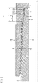
- FIG. 2 is a schematic longitudinal cross-sectional view of a threaded connection 1 for a steel pipe according to a first embodiment.
- Longitudinal cross section means a cross section taken along a plane containing the pipe axis CL of the threaded connection 1.
- Transverse cross section means a cross section taken along a plane perpendicular to the pipe axis CL.
- the present embodiment may be employed in an integral-type threaded connection, or may be employed in a coupling-type threaded connection.
- the threaded connection 1 includes a tubular pin 10 and a tubular box 20.
- the pin 10 is inserted into the box 20 such that the pin 10 and box 20 are made up.
- the pin 10 is provided adjacent to the steel pipe body 2.
- the steel pipe body 2 is a portion of the steel pipe including the pin 10 that is not within the box 20 after insertion.
- the steel pipe may be a steel pipe, for example.
- the direction toward the tip of the pin 10 may be referred to as forward direction or direction toward the front, and the direction toward the steel pipe body 2 may be referred to as rearward direction or direction toward the rear.
- the pin 10 includes a nose 11, a pin shoulder surface 12, a pin sealing surface 13 and a male thread 14.
- the pin shoulder surface 12, nose 11, pin sealing surface 13 and male thread 14 are arranged in this order as it goes from the front toward the rear of the pin 10.
- the portion of the pin 10 that is located forward of the male thread 14 will be referred to as pin lip 15.
- the pin lip 15 includes the nose 11, pin shoulder surface 12 and pin sealing surface 13.
- the nose 11 provides a tip portion of the pin 10.
- the nose 11 is cylindrical in shape.
- the outer peripheral surface of the nose 11 may have the shape corresponding to the outer peripheral surface of a cylinder or the shape corresponding to the outer peripheral surface of a truncated cone having an outer diameter that decreases as it goes toward the tip of the pin 10.
- the outer peripheral surface of the nose 11 may have the shape obtained by combining the outer peripheral surface of a cylinder and/or the outer peripheral surface of such a truncated cone and the outer peripheral surface of a solid of revolution obtained by rotating a curve such as an arc about the pipe axis CL.
- the tip surface of the nose 11, i.e. the tip surface of the pin 10, includes a pin shoulder surface 12.
- the pin shoulder surface 12 forms a portion or all of the tip surface of the pin 10.
- the pin shoulder surface 12 is a toroidal surface disposed to cross the pipe-axis direction.
- the pin shoulder surface 12 is inclined relative to a plane perpendicular to the pipe axis CL such that its outer periphery is located forward of the inner periphery.
- the pin shoulder surface 12 may be substantially perpendicular to the pipe axis CL.
- the pin sealing surface 13 is located closer to the steel pipe body 2 than the nose 11 is.
- the pin sealing surface 13 is located on the outer periphery of the pin 10.
- the pin sealing surface 13 is located adjacent to the nose 11.
- the pin sealing surface 13 includes a taper surface and/or curved surface.
- the pin sealing surface 13 has the shape corresponding to the outer peripheral surface of a truncated cone having an outer diameter that decreases as it goes toward the tip of the pin 10, or the shape corresponding to the outer peripheral surface of a solid of revolution obtained by rotating a curve such as an arc about the pipe axis CL.
- the pin sealing surface 13 may have the shape obtained by combining the outer peripheral surface of such a truncated cone and the peripheral surface of such a solid of revolution.
- the outer peripheral surface of the pin lip 15 includes a plurality of taper surfaces.
- the pin sealing surface 13 is generally formed by a taper surface
- the outer peripheral surface of the nose 11 is formed by a taper surface having a taper angle that is smaller (i.e. gentler) than the taper angle of the pin sealing surface 13.
- the outer peripheral surface of the pin lip 15 is formed by a plurality of taper surfaces. More specifically, the outer peripheral surface of the nose 11 is generally a taper surface.
- the pin sealing surface 13 is generally a taper surface. The taper angle of the outer peripheral surface of the nose 11 is smaller than the taper angle of the pin sealing surface 13. The slope of the outer peripheral surface of the pin lip 15 changes at the border between the nose 11 and pin sealing surface 13.
- the pin sealing surface 13 may be provided to the outer peripheral surface of the nose 11 via a curved surface.
- the portion of the outer peripheral surface of the pin lip 15 that is located rearward of the pin sealing surface 13 is generally a taper surface having a smaller taper angle than the pin sealing surface 13.
- the slope of the outer peripheral surface of the pin lip 15 changes at the border between the rearward portion and the pin sealing surface 13.
- the pin sealing surface 13 may be provided to the rearward portion via a curved surface. Alternatively, the rearward portion and the pin sealing surface 13 may be a single taper surface.
- the outer peripheral surface of the nose 11 and/or the portion of the outer peripheral surface of the pin lip 15 that is rearward of the pin sealing surface 13 may be formed by the outer peripheral surface of a cylinder.
- the distance between the seal position P of the pin sealing surface 13 and the front end of the male thread 14 as measured in the pipe-axis direction is denoted by x
- the distance between the tip of the pin 10 and the front end of the male thread 14 as measured in the pipe-axis direction is denoted by L.
- the distance L is the length of the pin lip 15. Seal position P and distances x and L will be described in detail further below.
- the male thread 14 is located rearward of the pin lip 15 as determined along the pipe-axis direction.
- the male thread 14 is provided on the outer periphery of the pin 10.
- the male thread 14 is constituted by a tapered thread.
- the box 20 includes a nose-receiving portion 21, a box shoulder surface 22, a box sealing surface 23, and a female thread 24.
- the direction toward the pipe end of the steel pipe or coupling with the box 20 may be referred to as outward direction or direction toward the exterior, and the opposite direction may be referred to as inward direction or direction toward the interior.
- the box shoulder surface 22, nose-receiving portion 21, box sealing surface 23 and female thread 24 are arranged in this order as it goes from the interior toward the exterior of the box 20.
- the nose-receiving portion 21 is a portion of the box 20 that corresponds to the nose 11 of the pin 10.
- the nose-receiving portion 21 provides an interior end portion of the box.
- the inner periphery of the nose-receiving portion 21 faces the outer periphery of the nose 11, with a clearance present therebetween. That is, when the connection has been made up, the outer periphery of the nose 11 is not in contact with the inner periphery of the box 20.
- the inner peripheral surface of the nose-receiving portion 21 is not limited to any particular shape.
- the inner peripheral surface of the nose-receiving portion 21 may be formed by the inner peripheral surface of a cylinder or may be formed by a taper surface having an inner diameter that decreases as it goes toward the interior of the box 20.
- the inner peripheral surface of the nose-receiving portion 21 may have the shape obtained by combining the inner peripheral surface of such a cylinder and/or such a taper surface and the inner peripheral surface of a solid of revolution obtained by rotating a curve such as an arc about the pipe axis CL.
- the box shoulder surface 22 is provided to correspond to the pin shoulder surface 12 and located in the interior region of the box 20. Similar to the pin shoulder surface 12, the box shoulder surface 22 is a toroidal surface disposed to cross the pipe-axis direction.
- the box shoulder surface 22 is in contact with the pin shoulder surface 12 and, together with the pin shoulder surface 12, forms a shoulder.
- the pin and box shoulder surfaces 12 and 22 serve as a stop for limiting screw-in of the pin 10.
- the pin and box shoulder surfaces 12 and 22 serve to generate a thread-tightening axial force inside the connection.
- the box sealing surface 23 is located outward of the nose-receiving portion 21 as determined along the pipe-axis direction.
- the box sealing surface 23 is provided to correspond to the pin sealing surface 13 and is located on the inner periphery of the box 20.
- the pin sealing surface 13 and box sealing surface 23 have an amount of interference. That is, when the connection is not made up, the pin sealing surface 13 has a diameter that is slightly larger than the diameter of the box sealing surface 23. When the connection has been made up, the pin sealing surface 13 and box sealing surface 23 are in tight contact with each other by interference fit. When the connection has been made up, the pin sealing surface 13 and box sealing surface 23 form a seal by metal-to-metal contact.
- the box sealing surface 23 may be shaped to protrude toward the pin sealing surface 13. Alternatively, the box sealing surface 23 may not protrude toward the pin sealing surface 13. It is only required that at least a portion of the box sealing surface 23 be capable of being in tight contact with the pin sealing surface when the connection has been made up.
- the box sealing surface 23 may be constructed to have various shapes.
- the female thread 24 is provided to correspond to the male thread 14 and is provided on the inner periphery of the box 20.
- the female thread 24 is constituted by a tapered thread that engages the tapered thread constituting the male thread 14. When the connection has been made up, the female thread 24, together with the male thread 14, forms a thread assembly.
- Each of the load flanks of the male thread 14 and female thread 24 has a flank angle smaller than 0°.
- each of the male thread 14 and female thread 24 may be constituted by a trapezoidal thread.
- Each of the male thread 14 and female thread 24 is preferably constituted by a single-start thread or a double-start thread.
- FIG. 3 is an enlarged longitudinal cross-sectional view of the tip portion of the pin 10.
- the thread crests of a front end portion of the male thread 14 are partially cut away to have an incomplete shape. These thread crests have a bevel 14a formed thereon, which is a slope inclined toward the tip and inner periphery of the pin 10.
- the front end of the male thread 14 is defined as the intersection of a line L14 extending from the bevel 14a and a line L15 extending from a portion 15a of the outer periphery of the pin lip 15 that is adjacent to the bevel 14a.
- Seal position P is the position of the portion of the pin sealing surface 13 that first contacts the inner peripheral surface of the box 20 ( FIG. 2 ) during make-up.
- L is the distance between the apex of the pin 10 and the front end of the male thread 14 as measured in the pipe-axis direction.
- x is the distance between seal position P and the front end of the male thread 14 as measured in the pipe-axis direction.
- the length L of the pin lip 15 and the distance x between seal position P and the front end of the male thread 14 are such that the value of x/L falls within a predetermined range. More specifically, x/L is not smaller than 0.4 and not larger than 0.55, and preferably not smaller than 0.4 and smaller than 0.5. The value of length L and the value of distance x are values found when the connection is not made up.
- the transverse cross section of the pin 10 as measured at seal position P is preferably not smaller than 35 % of the transverse cross section of the steel pipe body 2 ( FIG. 2 ), and more preferably not smaller than 50 %.
- the upper limit of the transverse cross section of the pin 10 as measured at seal position P may be 70 % of the transverse cross section of the steel pipe body 2, for example.
- integral-type threaded connection or may be a coupling-type threaded connection.
- the threaded connection 1A according to the present embodiment has the same construction as the threaded connection 1 according to the first embodiment except for the pin lip 15A and the portion of the box 20A that corresponds to the pin lip 15A.
- description will be focused on the differences between the present embodiment and first embodiment.
- the outer peripheral surface of the pin lip 15A is constituted by a convex curved surface 15b. That is, the outer peripheral surface of the pin lip 15A is a curved surface protruding toward the box 20A.
- the outer peripheral surface of the pin lip 15A is a smooth continuous surface whose curvature does not change rapidly over the entire surface.
- the outer peripheral surface of the pin lip 15A may be a convex curved surface with a single curvature, or may include a plurality of curved surfaces.
- the thread crests of a front end portion of the male thread 14 are partially cut away to have an incomplete shape. These thread crests have a bevel 14a formed thereon, which is a slope inclined toward the tip and inner periphery of the pin 10.
- the front end of the male thread 14 is defined as the intersection of a line L14 extending from the bevel 14a and a line L15 extending from the convex curved surface 15b on the outer periphery of the pin lip 15.
- the portion of the inner peripheral surface of the box 20A that corresponds to the pin lip 15A is shaped to correspond to the outer peripheral surface of the pin lip 15A. That is, the portion of the inner peripheral surface of the box 20A that corresponds to the pin lip 15A is shaped in such a manner that, when the connection has been made up, the box sealing surface 23A is in contact with the pin sealing surface 13A and the nose-receiving portion 21A is not in contact with the nose 11A.
- the box sealing surface 23A has a taper surface. However, the box sealing surface 23A is not limited to such a shape. Again, the box sealing surface 23A may have various shapes.
- x/L is not smaller than 0.4 and not
- a change in the value of x/L work both to improve and worsen sealing performance.
- the ultimate sealing performance depends on how to balance the influence of the value of x/L to improve sealing performance and the influence of the same value to worsen sealing performance.
- the threaded connections 1 and 1A according to the embodiments are each constructed such that x/L is not smaller than 0.4 and not larger than 0.55. This suitably balances the influence of the value of x/L to improve sealing performance and the influence of the same value to worsen sealing performance, thereby improving both external-pressure sealing performance and internal-pressure sealing performance.
- the transverse cross section of the pin 10, 10A as measured at seal position P is preferably not smaller than 35 % of the transverse cross section of the steel pipe body 2. This will provide sufficient transverse cross section of the seal, thereby maintaining high stiffness of the pin lip 15, 15A. This will further improve external-pressure sealing performance.
- the transverse cross section of the pin 10, 10A as measured at position P is preferably not larger than 70 % of the transverse cross section of the steel pipe body 2.
- sample models were used where the material was an isotropic-hardening elasto-plastic material with an elastic modulus of 210 GPa and a yield strength of 110 ksi (758.3 MPa), expressed as 0.2% proof stress.
- Table 1 shows the test conditions and evaluations for the samples.
- FIG. 4 is a graph where the values of x/L for the samples and the sealing performances against the internal and external pressures are plotted.
- Sample Pipe size x/L Sealing performance (contact force) Remarks Outer diameter [mm] Wall thickness [mm] Internal-pressure cycle External-pressure cycle Evaluation #1 177.8 10.4 0.19 0.92 1.16 poor comp. #2 177.8 10.4 0.27 0.89 1.15 poor comp. #3 177.8 10.4 0.35 0.94 1.13 poor comp. #4 177.8 10.4 0.40 1.04 1.14 excellent inv. #5 177.8 10.4 0.43 1.03 1.17 excellent inv. #6 177.8 10.4 0.46 1.04 1.12 excellent inv.
- Samples #4 to 8 are inventive examples that fall within the scope of the present disclosure, while samples #1 to 3 and 9 to 10 are comparative examples that fall outside the scope of the present disclosure. That is, for samples #4 to 8, x/L was not smaller than 0.4 and not larger than 0.55, and for samples #1 to 3 and 9 to 10, x/L was smaller than 0.4 or larger than 0.55.
- the external-pressure sealing performance was not smaller than 1.10, which was very good.
Landscapes
- Engineering & Computer Science (AREA)
- General Engineering & Computer Science (AREA)
- Mechanical Engineering (AREA)
- Life Sciences & Earth Sciences (AREA)
- Geology (AREA)
- Mining & Mineral Resources (AREA)
- Physics & Mathematics (AREA)
- Environmental & Geological Engineering (AREA)
- Fluid Mechanics (AREA)
- General Life Sciences & Earth Sciences (AREA)
- Geochemistry & Mineralogy (AREA)
- Non-Disconnectible Joints And Screw-Threaded Joints (AREA)
Claims (2)
- Gewindeverbindung (1) für Stahlrohre, die Folgendes umfasst:einen rohrförmigen Stift (10), der neben einem Stahlrohrkörper bereitgestellt ist; undein rohrförmiges Gehäuse (20), wobei der Stift (10) in das Gehäuse (20) eingesetzt wird, so dass das Gehäuse (20) und der Stift (10) verbunden sind,wobei der Stift (10) Folgendes umfasst:eine Nase (11), die einen Spitzenabschnitt des Stifts (10) bildet;eine Stiftschulterfläche (12), die auf einer Spitzenfläche der Nase (11) bereitgestellt ist;ein Außengewinde (14), das an einem Außenumfang des Stifts (10) bereitgestellt und näher am Stahlrohrkörper als die Nase (11) angeordnet ist; undeine Stiftdichtungsfläche (13), die am Außenumfang des Stifts (10) bereitgestellt und zwischen der Nase (11) und dem Außengewinde (14) angeordnet ist,wobei das Gehäuse (20) Folgendes umfasst:eine Gehäuseschulterfläche (22), die so bereitgestellt ist, dass sie der Stiftschulterfläche (12) entspricht, und die sich in einem Innenbereich des Gehäuses (20) befindet, wobei die Gehäuseschulterfläche (22) in Kontakt mit der Stiftschulterfläche (12) steht, wenn die Verbindung hergestellt ist;ein Innengewinde (24), das so bereitgestellt ist, dass es dem Außengewinde (14) entspricht, und das sich an einem Innenumfang des Gehäuses (20) befindet; undeine Gehäusedichtungsfläche (23), die so bereitgestellt ist, dass sie der Stiftdichtungsfläche (13) entspricht und am Innenumfang des Gehäuses (20) angeordnet ist, wobei die Gehäusedichtungsfläche (23) in Kontakt mit der Stiftdichtungsfläche (13) steht, wenn die Verbindung hergestellt ist,dadurch gekennzeichnet, dass die Stiftdichtungsfläche (13) durch eine konische Fläche gebildet wird,eine äußere Umfangsfläche der Nase (11) durch eine Kegelfläche mit einem Kegelwinkel gebildet wird, der kleiner als ein Kegelwinkel der Stiftdichtungsfläche (13) ist,wenn die Verbindung hergestellt ist, ein äußerer Umfang der Nase (11) dem inneren Umfang des Gehäuses (20) gegenüberliegt, wobei ein Spiel dazwischen vorhanden ist, und,die Gewindeverbindung die Bedingung 0,4 ≤ x/L ≤ 0,55 erfüllt, wobei x ein Abstand zwischen einer Dichtungsposition und dem Ende des Außengewindes (14), das an die Stiftdichtungsfläche (13) angrenzt, gemessen in Richtung der Rohrachse ist, wobei die Dichtungsposition eine Position der Stiftdichtungsfläche (13) ist, die den inneren Umfang des Gehäuses (20) während des Verbindens zuerst berührt, und L ein Abstand zwischen der Spitze des Stifts (10) und dem Ende des Außengewindes (14) neben der Stiftdichtungsfläche (13) ist, gemessen in Richtung der Rohrachse.
- Gewindeverbindung (1) für Stahlrohre nach Anspruch 1, wobei eine Querschnittsfläche des Stifts (10), gemessen an der Dichtungsposition, 35 % oder mehr einer Querschnittsfläche des Stahlrohrkörpers beträgt.
Applications Claiming Priority (2)
| Application Number | Priority Date | Filing Date | Title |
|---|---|---|---|
| JP2017101229 | 2017-05-22 | ||
| PCT/JP2018/014616 WO2018216366A1 (ja) | 2017-05-22 | 2018-04-05 | 鋼管用ねじ継手 |
Publications (3)
| Publication Number | Publication Date |
|---|---|
| EP3633255A1 EP3633255A1 (de) | 2020-04-08 |
| EP3633255A4 EP3633255A4 (de) | 2020-06-17 |
| EP3633255B1 true EP3633255B1 (de) | 2022-06-15 |
Family
ID=64396747
Family Applications (1)
| Application Number | Title | Priority Date | Filing Date |
|---|---|---|---|
| EP18806267.3A Active EP3633255B1 (de) | 2017-05-22 | 2018-04-05 | Schraubverbindung für stahlröhre |
Country Status (11)
| Country | Link |
|---|---|
| US (1) | US11339901B2 (de) |
| EP (1) | EP3633255B1 (de) |
| JP (1) | JP6900470B2 (de) |
| CN (1) | CN110651149B (de) |
| AR (1) | AR111799A1 (de) |
| AU (1) | AU2018273320B2 (de) |
| BR (1) | BR112019020896B1 (de) |
| CA (1) | CA3064361C (de) |
| EA (1) | EA037807B1 (de) |
| MX (1) | MX2019012982A (de) |
| WO (1) | WO2018216366A1 (de) |
Families Citing this family (1)
| Publication number | Priority date | Publication date | Assignee | Title |
|---|---|---|---|---|
| CN121127664A (zh) * | 2023-05-18 | 2025-12-12 | 国民油井华高有限公司 | 采用金属对金属密封的螺纹式管状构件 |
Family Cites Families (31)
| Publication number | Priority date | Publication date | Assignee | Title |
|---|---|---|---|---|
| US2992019A (en) * | 1958-07-07 | 1961-07-11 | Hydril Co | Casing joint having metal-to-metal sealing means responsive to fluid pressure |
| NL155335C (de) * | 1971-07-09 | 1900-01-01 | ||
| JPS5211765B2 (de) * | 1972-03-31 | 1977-04-02 | ||
| JPS58157087U (ja) | 1982-04-16 | 1983-10-20 | 日本鋼管株式会社 | 油井管用ネジ継手 |
| US5066052A (en) * | 1989-03-08 | 1991-11-19 | Baroid Technology, Inc. | Threaded pipe joint having improved seal ring entrapment |
| FR2733570B1 (fr) * | 1995-04-28 | 1997-06-20 | Vallourec Oil & Gas | Assemblage filete pour tubes |
| GB9706084D0 (en) * | 1997-03-24 | 1997-05-14 | Oil States Ind Uk Ltd | Improvements in and relating to pipe connectors |
| US20040108720A1 (en) * | 2001-08-06 | 2004-06-10 | Mallis David L. | Double flex seal for tubular connection |
| FR2833335B1 (fr) * | 2001-12-07 | 2007-05-18 | Vallourec Mannesmann Oil & Gas | Joint filete tubulaire superieur contenant au moins un element filete avec levre d'extremite |
| UA82694C2 (uk) | 2003-06-06 | 2008-05-12 | Sumitomo Metal Ind | Нарізне з'єднання для сталевих труб |
| JP2005351324A (ja) * | 2004-06-09 | 2005-12-22 | Metal One Corp | 油井管用ネジ継手 |
| FR2889727B1 (fr) * | 2005-08-09 | 2007-09-28 | Vallourec Mannesmann Oil Gas F | Joint filete tubulaire etanche aux liquides et aux gaz |
| JP5100755B2 (ja) * | 2007-10-03 | 2012-12-19 | 住友金属工業株式会社 | 鋼管用ねじ継手 |
| FR2923283B1 (fr) * | 2007-11-07 | 2012-10-05 | Vallourec Mannesmann Oil & Gas | Joint filete comprenant au moins un element filete avec levre d'extremite pour tube metallique. |
| WO2009060552A1 (en) * | 2007-11-08 | 2009-05-14 | Sumitomo Metal Industries, Ltd. | Threaded joint for steel pipes |
| EP2337982B1 (de) * | 2008-10-20 | 2018-02-28 | Nippon Steel & Sumitomo Metal Corporation | Schraubverbindung für stahlrohre |
| JP4930647B1 (ja) * | 2010-06-30 | 2012-05-16 | Jfeスチール株式会社 | 管用ねじ継手 |
| WO2012056500A1 (ja) * | 2010-10-29 | 2012-05-03 | 株式会社メタルワン | 油井管用ネジ継ぎ手 |
| GB201019413D0 (en) * | 2010-11-17 | 2010-12-29 | Hsc Fzco | An improved seal between pipes |
| JP5776222B2 (ja) | 2011-02-28 | 2015-09-09 | Jfeスチール株式会社 | 鋼管用ねじ継手 |
| JP5849749B2 (ja) * | 2011-02-28 | 2016-02-03 | Jfeスチール株式会社 | 管用ねじ継手 |
| JP5690021B2 (ja) * | 2012-01-19 | 2015-03-25 | 新日鐵住金株式会社 | 管ねじ継手 |
| JP2014013052A (ja) * | 2012-07-04 | 2014-01-23 | Jfe Steel Corp | 管のねじ継手 |
| FR3027338B1 (fr) * | 2014-10-16 | 2016-12-02 | Vallourec Oil & Gas France | Connexion polyvalente etanche a double butee |
| MX377322B (es) * | 2015-01-15 | 2025-03-07 | Jfe Steel Corp | Junta atornillada para tubo. |
| US10006569B2 (en) * | 2015-02-19 | 2018-06-26 | Arcelormittal Tubular Products Luxembourg S.A. | Threaded connection for pipes, such as oil and gas pipes |
| JP6640347B2 (ja) * | 2016-06-08 | 2020-02-05 | 日本製鉄株式会社 | 鋼管用ねじ継手 |
| FR3060701A1 (fr) * | 2016-12-16 | 2018-06-22 | Vallourec Oil And Gas France | Joint filete pour composant tubulaire |
| RU2720524C1 (ru) * | 2017-01-18 | 2020-04-30 | Ниппон Стил Корпорейшн | Резьбовое соединение для стальных труб |
| US20180252343A1 (en) * | 2017-03-03 | 2018-09-06 | Arcelormittal Tubular Products Luxembourg S.A. | Torque shoulder of a premium connection |
| JP6804664B2 (ja) * | 2017-11-09 | 2020-12-23 | 日本製鉄株式会社 | 鋼管用ねじ継手 |
-
2018
- 2018-04-05 EP EP18806267.3A patent/EP3633255B1/de active Active
- 2018-04-05 US US16/613,598 patent/US11339901B2/en active Active
- 2018-04-05 CN CN201880033611.2A patent/CN110651149B/zh active Active
- 2018-04-05 BR BR112019020896-8A patent/BR112019020896B1/pt active IP Right Grant
- 2018-04-05 EA EA201992499A patent/EA037807B1/ru unknown
- 2018-04-05 AU AU2018273320A patent/AU2018273320B2/en not_active Expired - Fee Related
- 2018-04-05 WO PCT/JP2018/014616 patent/WO2018216366A1/ja not_active Ceased
- 2018-04-05 CA CA3064361A patent/CA3064361C/en active Active
- 2018-04-05 MX MX2019012982A patent/MX2019012982A/es unknown
- 2018-04-05 JP JP2019519503A patent/JP6900470B2/ja active Active
- 2018-05-16 AR ARP180101286A patent/AR111799A1/es active IP Right Grant
Also Published As
| Publication number | Publication date |
|---|---|
| MX2019012982A (es) | 2019-12-18 |
| CA3064361C (en) | 2022-04-12 |
| AU2018273320B2 (en) | 2020-11-26 |
| EA037807B1 (ru) | 2021-05-24 |
| AU2018273320A1 (en) | 2019-11-07 |
| JP6900470B2 (ja) | 2021-07-07 |
| US20200200304A1 (en) | 2020-06-25 |
| AR111799A1 (es) | 2019-08-21 |
| CA3064361A1 (en) | 2018-11-29 |
| WO2018216366A1 (ja) | 2018-11-29 |
| BR112019020896A2 (pt) | 2020-04-28 |
| CN110651149A (zh) | 2020-01-03 |
| BR112019020896B1 (pt) | 2023-01-24 |
| CN110651149B (zh) | 2021-05-07 |
| JPWO2018216366A1 (ja) | 2019-07-04 |
| EP3633255A1 (de) | 2020-04-08 |
| EP3633255A4 (de) | 2020-06-17 |
| EA201992499A1 (ru) | 2020-03-19 |
| US11339901B2 (en) | 2022-05-24 |
Similar Documents
| Publication | Publication Date | Title |
|---|---|---|
| US11629560B2 (en) | Threaded connection for steel pipe | |
| EP3366968B1 (de) | Gewindeanschluss für stahlrohre | |
| US12018777B2 (en) | Threaded connection for steel pipe | |
| EP3708892B1 (de) | Gewindeverbindung für stahlrohre | |
| JP6311019B2 (ja) | 鋼管用ねじ継手 | |
| AU2016373923B2 (en) | Threaded joint for steel pipe | |
| CN102313085A (zh) | 管用螺纹接头 | |
| US11506311B2 (en) | Threaded connection for steel pipe | |
| EP3862607B1 (de) | Schraubverbindung für stahlrohre | |
| EP3572702B1 (de) | Schraubverbindung für stahlrohre | |
| EP3633255A1 (de) | Schraubverbindung für stahlrohr | |
| EP3842680B1 (de) | Schraubverbindung für stahlrohre | |
| OA19509A (en) | Screw Joint For Steel Pipe. | |
| CA3169103C (en) | Threaded connection for steel pipe | |
| OA21386A (en) | Threaded joint for steel pipe. | |
| OA19670A (en) | Threaded joint steel pipes. |
Legal Events
| Date | Code | Title | Description |
|---|---|---|---|
| STAA | Information on the status of an ep patent application or granted ep patent |
Free format text: STATUS: THE INTERNATIONAL PUBLICATION HAS BEEN MADE |
|
| PUAI | Public reference made under article 153(3) epc to a published international application that has entered the european phase |
Free format text: ORIGINAL CODE: 0009012 |
|
| STAA | Information on the status of an ep patent application or granted ep patent |
Free format text: STATUS: REQUEST FOR EXAMINATION WAS MADE |
|
| 17P | Request for examination filed |
Effective date: 20191014 |
|
| AK | Designated contracting states |
Kind code of ref document: A1 Designated state(s): AL AT BE BG CH CY CZ DE DK EE ES FI FR GB GR HR HU IE IS IT LI LT LU LV MC MK MT NL NO PL PT RO RS SE SI SK SM TR |
|
| AX | Request for extension of the european patent |
Extension state: BA ME |
|
| A4 | Supplementary search report drawn up and despatched |
Effective date: 20200520 |
|
| RIC1 | Information provided on ipc code assigned before grant |
Ipc: F16L 15/04 20060101AFI20200514BHEP Ipc: F16L 15/00 20060101ALI20200514BHEP Ipc: E21B 17/042 20060101ALI20200514BHEP |
|
| DAV | Request for validation of the european patent (deleted) | ||
| DAX | Request for extension of the european patent (deleted) | ||
| GRAP | Despatch of communication of intention to grant a patent |
Free format text: ORIGINAL CODE: EPIDOSNIGR1 |
|
| STAA | Information on the status of an ep patent application or granted ep patent |
Free format text: STATUS: GRANT OF PATENT IS INTENDED |
|
| INTG | Intention to grant announced |
Effective date: 20220318 |
|
| GRAS | Grant fee paid |
Free format text: ORIGINAL CODE: EPIDOSNIGR3 |
|
| GRAA | (expected) grant |
Free format text: ORIGINAL CODE: 0009210 |
|
| STAA | Information on the status of an ep patent application or granted ep patent |
Free format text: STATUS: THE PATENT HAS BEEN GRANTED |
|
| AK | Designated contracting states |
Kind code of ref document: B1 Designated state(s): AL AT BE BG CH CY CZ DE DK EE ES FI FR GB GR HR HU IE IS IT LI LT LU LV MC MK MT NL NO PL PT RO RS SE SI SK SM TR |
|
| REG | Reference to a national code |
Ref country code: CH Ref legal event code: EP Ref country code: GB Ref legal event code: FG4D |
|
| REG | Reference to a national code |
Ref country code: RO Ref legal event code: EPE |
|
| REG | Reference to a national code |
Ref country code: IE Ref legal event code: FG4D |
|
| REG | Reference to a national code |
Ref country code: DE Ref legal event code: R096 Ref document number: 602018036827 Country of ref document: DE |
|
| REG | Reference to a national code |
Ref country code: AT Ref legal event code: REF Ref document number: 1498586 Country of ref document: AT Kind code of ref document: T Effective date: 20220715 |
|
| REG | Reference to a national code |
Ref country code: NO Ref legal event code: T2 Effective date: 20220615 |
|
| REG | Reference to a national code |
Ref country code: LT Ref legal event code: MG9D |
|
| REG | Reference to a national code |
Ref country code: NL Ref legal event code: MP Effective date: 20220615 |
|
| PG25 | Lapsed in a contracting state [announced via postgrant information from national office to epo] |
Ref country code: SE Free format text: LAPSE BECAUSE OF FAILURE TO SUBMIT A TRANSLATION OF THE DESCRIPTION OR TO PAY THE FEE WITHIN THE PRESCRIBED TIME-LIMIT Effective date: 20220615 Ref country code: LT Free format text: LAPSE BECAUSE OF FAILURE TO SUBMIT A TRANSLATION OF THE DESCRIPTION OR TO PAY THE FEE WITHIN THE PRESCRIBED TIME-LIMIT Effective date: 20220615 Ref country code: HR Free format text: LAPSE BECAUSE OF FAILURE TO SUBMIT A TRANSLATION OF THE DESCRIPTION OR TO PAY THE FEE WITHIN THE PRESCRIBED TIME-LIMIT Effective date: 20220615 Ref country code: GR Free format text: LAPSE BECAUSE OF FAILURE TO SUBMIT A TRANSLATION OF THE DESCRIPTION OR TO PAY THE FEE WITHIN THE PRESCRIBED TIME-LIMIT Effective date: 20220916 Ref country code: FI Free format text: LAPSE BECAUSE OF FAILURE TO SUBMIT A TRANSLATION OF THE DESCRIPTION OR TO PAY THE FEE WITHIN THE PRESCRIBED TIME-LIMIT Effective date: 20220615 Ref country code: BG Free format text: LAPSE BECAUSE OF FAILURE TO SUBMIT A TRANSLATION OF THE DESCRIPTION OR TO PAY THE FEE WITHIN THE PRESCRIBED TIME-LIMIT Effective date: 20220915 |
|
| PG25 | Lapsed in a contracting state [announced via postgrant information from national office to epo] |
Ref country code: RS Free format text: LAPSE BECAUSE OF FAILURE TO SUBMIT A TRANSLATION OF THE DESCRIPTION OR TO PAY THE FEE WITHIN THE PRESCRIBED TIME-LIMIT Effective date: 20220615 Ref country code: LV Free format text: LAPSE BECAUSE OF FAILURE TO SUBMIT A TRANSLATION OF THE DESCRIPTION OR TO PAY THE FEE WITHIN THE PRESCRIBED TIME-LIMIT Effective date: 20220615 |
|
| PG25 | Lapsed in a contracting state [announced via postgrant information from national office to epo] |
Ref country code: NL Free format text: LAPSE BECAUSE OF FAILURE TO SUBMIT A TRANSLATION OF THE DESCRIPTION OR TO PAY THE FEE WITHIN THE PRESCRIBED TIME-LIMIT Effective date: 20220615 |
|
| PG25 | Lapsed in a contracting state [announced via postgrant information from national office to epo] |
Ref country code: SM Free format text: LAPSE BECAUSE OF FAILURE TO SUBMIT A TRANSLATION OF THE DESCRIPTION OR TO PAY THE FEE WITHIN THE PRESCRIBED TIME-LIMIT Effective date: 20220615 Ref country code: SK Free format text: LAPSE BECAUSE OF FAILURE TO SUBMIT A TRANSLATION OF THE DESCRIPTION OR TO PAY THE FEE WITHIN THE PRESCRIBED TIME-LIMIT Effective date: 20220615 Ref country code: PT Free format text: LAPSE BECAUSE OF FAILURE TO SUBMIT A TRANSLATION OF THE DESCRIPTION OR TO PAY THE FEE WITHIN THE PRESCRIBED TIME-LIMIT Effective date: 20221017 Ref country code: ES Free format text: LAPSE BECAUSE OF FAILURE TO SUBMIT A TRANSLATION OF THE DESCRIPTION OR TO PAY THE FEE WITHIN THE PRESCRIBED TIME-LIMIT Effective date: 20220615 Ref country code: EE Free format text: LAPSE BECAUSE OF FAILURE TO SUBMIT A TRANSLATION OF THE DESCRIPTION OR TO PAY THE FEE WITHIN THE PRESCRIBED TIME-LIMIT Effective date: 20220615 Ref country code: CZ Free format text: LAPSE BECAUSE OF FAILURE TO SUBMIT A TRANSLATION OF THE DESCRIPTION OR TO PAY THE FEE WITHIN THE PRESCRIBED TIME-LIMIT Effective date: 20220615 |
|
| PG25 | Lapsed in a contracting state [announced via postgrant information from national office to epo] |
Ref country code: PL Free format text: LAPSE BECAUSE OF FAILURE TO SUBMIT A TRANSLATION OF THE DESCRIPTION OR TO PAY THE FEE WITHIN THE PRESCRIBED TIME-LIMIT Effective date: 20220615 Ref country code: IS Free format text: LAPSE BECAUSE OF FAILURE TO SUBMIT A TRANSLATION OF THE DESCRIPTION OR TO PAY THE FEE WITHIN THE PRESCRIBED TIME-LIMIT Effective date: 20221015 |
|
| REG | Reference to a national code |
Ref country code: DE Ref legal event code: R097 Ref document number: 602018036827 Country of ref document: DE |
|
| PG25 | Lapsed in a contracting state [announced via postgrant information from national office to epo] |
Ref country code: AL Free format text: LAPSE BECAUSE OF FAILURE TO SUBMIT A TRANSLATION OF THE DESCRIPTION OR TO PAY THE FEE WITHIN THE PRESCRIBED TIME-LIMIT Effective date: 20220615 |
|
| PLBE | No opposition filed within time limit |
Free format text: ORIGINAL CODE: 0009261 |
|
| STAA | Information on the status of an ep patent application or granted ep patent |
Free format text: STATUS: NO OPPOSITION FILED WITHIN TIME LIMIT |
|
| PG25 | Lapsed in a contracting state [announced via postgrant information from national office to epo] |
Ref country code: DK Free format text: LAPSE BECAUSE OF FAILURE TO SUBMIT A TRANSLATION OF THE DESCRIPTION OR TO PAY THE FEE WITHIN THE PRESCRIBED TIME-LIMIT Effective date: 20220615 |
|
| 26N | No opposition filed |
Effective date: 20230316 |
|
| PG25 | Lapsed in a contracting state [announced via postgrant information from national office to epo] |
Ref country code: SI Free format text: LAPSE BECAUSE OF FAILURE TO SUBMIT A TRANSLATION OF THE DESCRIPTION OR TO PAY THE FEE WITHIN THE PRESCRIBED TIME-LIMIT Effective date: 20220615 |
|
| REG | Reference to a national code |
Ref country code: AT Ref legal event code: UEP Ref document number: 1498586 Country of ref document: AT Kind code of ref document: T Effective date: 20220615 |
|
| REG | Reference to a national code |
Ref country code: CH Ref legal event code: PL |
|
| PG25 | Lapsed in a contracting state [announced via postgrant information from national office to epo] |
Ref country code: LU Free format text: LAPSE BECAUSE OF NON-PAYMENT OF DUE FEES Effective date: 20230405 |
|
| REG | Reference to a national code |
Ref country code: BE Ref legal event code: MM Effective date: 20230430 |
|
| PG25 | Lapsed in a contracting state [announced via postgrant information from national office to epo] |
Ref country code: MC Free format text: LAPSE BECAUSE OF FAILURE TO SUBMIT A TRANSLATION OF THE DESCRIPTION OR TO PAY THE FEE WITHIN THE PRESCRIBED TIME-LIMIT Effective date: 20220615 |
|
| PG25 | Lapsed in a contracting state [announced via postgrant information from national office to epo] |
Ref country code: MC Free format text: LAPSE BECAUSE OF FAILURE TO SUBMIT A TRANSLATION OF THE DESCRIPTION OR TO PAY THE FEE WITHIN THE PRESCRIBED TIME-LIMIT Effective date: 20220615 Ref country code: LI Free format text: LAPSE BECAUSE OF NON-PAYMENT OF DUE FEES Effective date: 20230430 Ref country code: CH Free format text: LAPSE BECAUSE OF NON-PAYMENT OF DUE FEES Effective date: 20230430 |
|
| REG | Reference to a national code |
Ref country code: IE Ref legal event code: MM4A |
|
| PG25 | Lapsed in a contracting state [announced via postgrant information from national office to epo] |
Ref country code: BE Free format text: LAPSE BECAUSE OF NON-PAYMENT OF DUE FEES Effective date: 20230430 |
|
| PG25 | Lapsed in a contracting state [announced via postgrant information from national office to epo] |
Ref country code: IE Free format text: LAPSE BECAUSE OF NON-PAYMENT OF DUE FEES Effective date: 20230405 |
|
| PG25 | Lapsed in a contracting state [announced via postgrant information from national office to epo] |
Ref country code: IE Free format text: LAPSE BECAUSE OF NON-PAYMENT OF DUE FEES Effective date: 20230405 |
|
| PG25 | Lapsed in a contracting state [announced via postgrant information from national office to epo] |
Ref country code: BG Free format text: LAPSE BECAUSE OF FAILURE TO SUBMIT A TRANSLATION OF THE DESCRIPTION OR TO PAY THE FEE WITHIN THE PRESCRIBED TIME-LIMIT Effective date: 20220615 |
|
| PG25 | Lapsed in a contracting state [announced via postgrant information from national office to epo] |
Ref country code: BG Free format text: LAPSE BECAUSE OF FAILURE TO SUBMIT A TRANSLATION OF THE DESCRIPTION OR TO PAY THE FEE WITHIN THE PRESCRIBED TIME-LIMIT Effective date: 20220615 |
|
| PG25 | Lapsed in a contracting state [announced via postgrant information from national office to epo] |
Ref country code: CY Free format text: LAPSE BECAUSE OF FAILURE TO SUBMIT A TRANSLATION OF THE DESCRIPTION OR TO PAY THE FEE WITHIN THE PRESCRIBED TIME-LIMIT; INVALID AB INITIO Effective date: 20180405 |
|
| PG25 | Lapsed in a contracting state [announced via postgrant information from national office to epo] |
Ref country code: HU Free format text: LAPSE BECAUSE OF FAILURE TO SUBMIT A TRANSLATION OF THE DESCRIPTION OR TO PAY THE FEE WITHIN THE PRESCRIBED TIME-LIMIT; INVALID AB INITIO Effective date: 20180405 |
|
| PG25 | Lapsed in a contracting state [announced via postgrant information from national office to epo] |
Ref country code: TR Free format text: LAPSE BECAUSE OF FAILURE TO SUBMIT A TRANSLATION OF THE DESCRIPTION OR TO PAY THE FEE WITHIN THE PRESCRIBED TIME-LIMIT Effective date: 20220615 |
|
| PGFP | Annual fee paid to national office [announced via postgrant information from national office to epo] |
Ref country code: GB Payment date: 20260313 Year of fee payment: 9 |
|
| PGFP | Annual fee paid to national office [announced via postgrant information from national office to epo] |
Ref country code: RO Payment date: 20260318 Year of fee payment: 9 Ref country code: IT Payment date: 20260320 Year of fee payment: 9 |
|
| PGFP | Annual fee paid to national office [announced via postgrant information from national office to epo] |
Ref country code: FR Payment date: 20260309 Year of fee payment: 9 |
|
| PGFP | Annual fee paid to national office [announced via postgrant information from national office to epo] |
Ref country code: DE Payment date: 20260305 Year of fee payment: 9 |
|
| PGFP | Annual fee paid to national office [announced via postgrant information from national office to epo] |
Ref country code: NO Payment date: 20260409 Year of fee payment: 9 |
|
| PGFP | Annual fee paid to national office [announced via postgrant information from national office to epo] |
Ref country code: AT Payment date: 20260325 Year of fee payment: 9 |