EP3633352A1 - Verfahren und anordnung zum relativen referenzieren eines zielgases in einem optischen messsystem für die laserspektroskopie - Google Patents
Verfahren und anordnung zum relativen referenzieren eines zielgases in einem optischen messsystem für die laserspektroskopie Download PDFInfo
- Publication number
- EP3633352A1 EP3633352A1 EP19160093.1A EP19160093A EP3633352A1 EP 3633352 A1 EP3633352 A1 EP 3633352A1 EP 19160093 A EP19160093 A EP 19160093A EP 3633352 A1 EP3633352 A1 EP 3633352A1
- Authority
- EP
- European Patent Office
- Prior art keywords
- current
- gas
- act
- cal
- target gas
- Prior art date
- Legal status (The legal status is an assumption and is not a legal conclusion. Google has not performed a legal analysis and makes no representation as to the accuracy of the status listed.)
- Granted
Links
Images


Classifications
-
- G—PHYSICS
- G01—MEASURING; TESTING
- G01N—INVESTIGATING OR ANALYSING MATERIALS BY DETERMINING THEIR CHEMICAL OR PHYSICAL PROPERTIES
- G01N21/00—Investigating or analysing materials by the use of optical means, i.e. using sub-millimetre waves, infrared, visible or ultraviolet light
- G01N21/17—Systems in which incident light is modified in accordance with the properties of the material investigated
- G01N21/25—Colour; Spectral properties, i.e. comparison of effect of material on the light at two or more different wavelengths or wavelength bands
- G01N21/31—Investigating relative effect of material at wavelengths characteristic of specific elements or molecules, e.g. atomic absorption spectrometry
- G01N21/39—Investigating relative effect of material at wavelengths characteristic of specific elements or molecules, e.g. atomic absorption spectrometry using tunable lasers
-
- G—PHYSICS
- G01—MEASURING; TESTING
- G01J—MEASUREMENT OF INTENSITY, VELOCITY, SPECTRAL CONTENT, POLARISATION, PHASE OR PULSE CHARACTERISTICS OF INFRARED, VISIBLE OR ULTRAVIOLET LIGHT; COLORIMETRY; RADIATION PYROMETRY
- G01J3/00—Spectrometry; Spectrophotometry; Monochromators; Measuring colours
- G01J3/02—Details
- G01J3/0297—Constructional arrangements for removing other types of optical noise or for performing calibration
-
- G—PHYSICS
- G01—MEASURING; TESTING
- G01J—MEASUREMENT OF INTENSITY, VELOCITY, SPECTRAL CONTENT, POLARISATION, PHASE OR PULSE CHARACTERISTICS OF INFRARED, VISIBLE OR ULTRAVIOLET LIGHT; COLORIMETRY; RADIATION PYROMETRY
- G01J3/00—Spectrometry; Spectrophotometry; Monochromators; Measuring colours
- G01J3/02—Details
- G01J3/10—Arrangements of light sources specially adapted for spectrometry or colorimetry
-
- G—PHYSICS
- G01—MEASURING; TESTING
- G01J—MEASUREMENT OF INTENSITY, VELOCITY, SPECTRAL CONTENT, POLARISATION, PHASE OR PULSE CHARACTERISTICS OF INFRARED, VISIBLE OR ULTRAVIOLET LIGHT; COLORIMETRY; RADIATION PYROMETRY
- G01J3/00—Spectrometry; Spectrophotometry; Monochromators; Measuring colours
- G01J3/28—Investigating the spectrum
- G01J3/42—Absorption spectrometry; Double beam spectrometry; Flicker spectrometry; Reflection spectrometry
- G01J3/433—Modulation spectrometry; Derivative spectrometry
-
- G—PHYSICS
- G01—MEASURING; TESTING
- G01N—INVESTIGATING OR ANALYSING MATERIALS BY DETERMINING THEIR CHEMICAL OR PHYSICAL PROPERTIES
- G01N21/00—Investigating or analysing materials by the use of optical means, i.e. using sub-millimetre waves, infrared, visible or ultraviolet light
- G01N21/01—Arrangements or apparatus for facilitating the optical investigation
-
- G—PHYSICS
- G01—MEASURING; TESTING
- G01J—MEASUREMENT OF INTENSITY, VELOCITY, SPECTRAL CONTENT, POLARISATION, PHASE OR PULSE CHARACTERISTICS OF INFRARED, VISIBLE OR ULTRAVIOLET LIGHT; COLORIMETRY; RADIATION PYROMETRY
- G01J3/00—Spectrometry; Spectrophotometry; Monochromators; Measuring colours
- G01J3/28—Investigating the spectrum
- G01J3/42—Absorption spectrometry; Double beam spectrometry; Flicker spectrometry; Reflection spectrometry
- G01J3/433—Modulation spectrometry; Derivative spectrometry
- G01J2003/4334—Modulation spectrometry; Derivative spectrometry by modulation of source, e.g. current modulation
-
- G—PHYSICS
- G01—MEASURING; TESTING
- G01N—INVESTIGATING OR ANALYSING MATERIALS BY DETERMINING THEIR CHEMICAL OR PHYSICAL PROPERTIES
- G01N21/00—Investigating or analysing materials by the use of optical means, i.e. using sub-millimetre waves, infrared, visible or ultraviolet light
- G01N21/17—Systems in which incident light is modified in accordance with the properties of the material investigated
- G01N21/25—Colour; Spectral properties, i.e. comparison of effect of material on the light at two or more different wavelengths or wavelength bands
- G01N21/31—Investigating relative effect of material at wavelengths characteristic of specific elements or molecules, e.g. atomic absorption spectrometry
- G01N21/39—Investigating relative effect of material at wavelengths characteristic of specific elements or molecules, e.g. atomic absorption spectrometry using tunable lasers
- G01N2021/396—Type of laser source
- G01N2021/399—Diode laser
Definitions
- the invention relates to a method for operating an optical measuring system for measuring the concentration of a target gas component (ZG) in a measuring gas, with a wavelength-stabilized temperature-stabilized laser light source, wherein a current base current I DC_ZG, act corresponding to a wavelength ⁇ ZG of a target gas absorption line, is set in this way becomes that after a calibration the wavelength distance ⁇ DC between the wavelength ⁇ ZG of the target gas absorption line of a target gas component (ZG) and the wavelength ⁇ RG of a reference gas absorption line of a reference gas component (RG) for different values of the current base current I DC_ZG, act of the target gas component (ZG) and the current base current I DC_RG, act of the reference gas component (RG) is maintained.
- the invention also relates to an arrangement for carrying out the method.
- Optical measuring systems for measuring the concentration of a gas component in a measuring gas are known from the prior art in a variety of embodiments, as are a large number of different methods for operating such an optical measuring system, such as the wavelength Modulation spectroscopy (WMS) and direct absorption spectroscopy (DAS).
- WMS wavelength Modulation spectroscopy
- DAS direct absorption spectroscopy
- the exact setting of the laser wavelength to the wavelength of the absorption line of the target gas generally plays an important role.
- the laser wavelength is usually defined via the operating point of the Peltier temperature (basic laser temperature) and the basic current I DC of the laser light source.
- Base current is usually referred to as a direct current (DC) at which the absorption line has its maximum and by which larger and smaller current values are traversed when the absorption line is scanned.
- DC direct current
- one or more absorption line (s) of a reference gas are usually used and the principle of line locking is applied.
- the reference gas is either quasi-permanently contained in the process gas or is enclosed in a cuvette, for example, somewhere in the sensor itself.
- the cuvette can be implemented in the measuring beam path or in a special reference beam path (requires a beam splitter and another photodiode).
- the line thickness is too low, which results from a too short absorption section and leads to a too small absorption signal, or is too dangerous to manufacture or operate.
- another gas can be used instead of the target gas, which has one or more absorption line (s) in the vicinity of a target wavelength.
- reference gas a gas
- An example is the EP 2 307 876 B1 referred.
- patent two CH4 gas absorption lines are used to precisely reference the CO gas absorption line in the middle.
- the tuning range of the laser light source is often not wide enough to accurately reference a target gas absorption line.
- the EP 2 307 876 B1 discloses a method for the detection of at least one target gas by means of laser spectroscopy, with a laser light source whose emission wavelength is monochrome and can be tuned by means of a variation in the operating temperature or the operating current.
- the laser light source is first tuned over a first tuning width, at least two absorption lines of a reference gas and at least one absorption line of the at least one target gas being contained .
- a second tuning of the laser light source over a second tuning width in the wavelength range of the band of the at least one target gas, the second tuning width being narrower than the first tuning width, and at least one of the at least one absorption line of the at least one target gas being contained.
- the target gas and reference gas are different gases.
- the first vote for calibration of the laser current or the laser temperature with the absolute wavelength scale is carried out once and the second vote for the detection of the at least one target gas is carried out several times in succession.
- the second tuning width is compared to a calculated absorption spectrum, wherein a non-iterative curve fitting with a linear regression algorithm is used to calculate the concentration of the at least one target gas in one step.
- This procedure requires a reference gas that has at least two absorption lines near the target gas absorption line that are in the tuning range of the laser. In addition, this procedure is time-consuming since two reference lines have to be detected and evaluated.
- From the DE 10 2013 202 289 A1 is for driving a wavelength-tunable laser diode in a spectrometer without one Known reference gas to specify a power-time function, according to which the laser diode is periodically tuned over a wavelength range by determining a current profile from the power-time function and measured values of the voltage applied to the laser diode, with which the laser diode is controlled.
- the current profile with which the laser diode is directly controlled is generated by a control device as a function of the control deviation between the power consumption (actual size) of the laser diode and the specified power-time function (setpoint size), the at the Laser diode applied voltage and the current through the laser diode continuously detected, for. B.
- the power consumption of the laser diode is continuously determined by multiplying the measured current and voltage values.
- No reference gas is used there, so that when the temperature of the Peltier element (Peltier temperature) on which a laser chip is arranged and / or the outside temperature changes, a different wavelength range is detected despite the specified power-time function.
- This method is too imprecise for referencing a target gas.
- the total voltage across the laser is measured, which is too imprecise for the wavelength determination.
- the wavelength distance ⁇ DC between target gas and reference gas is kept constant during operation for different laser currents and thus different laser temperatures.
- the distance must remain constant even as the laser ages. In principle, you could simply scan a certain waveband.
- the detection limit is severely limited due to the noise (noise) resulting from, for example, optical interference phenomena and the presence of absorption lines of other gases in the measured spectrum. It is therefore important to adhere to the wavelength gap very precisely.
- the wavelength distance between target gas and reference gas is set by a constant current distance ⁇ I. Due to the non-linear DC tuning behavior of the laser, a shift (drift) of the operating point, for example due to the influence of the outside temperature on the temperature stabilization or the aging of the laser / electronics, leads to a distance error in the wavelength distance. As a result, the target gas component (absorption line of the target gas) is assumed to be in the wrong place. This may result in significant measurement errors.
- the object of the claimed invention is to propose another more precise, effective and easy-to-implement possibility of changing the wavelength distance between the target and reference gas lines in spite of changing laser properties, e.g. Operating current, temperature, long-term drift to keep constant.
- the main idea of the invention is to calculate the assumed wavelength position of the target gas instead of a fixed current difference value so that the current difference between the reference and target gas (peak) position, ie between the respective absorption lines, maintain a predefined temperature difference becomes.
- This temperature difference is calculated from the difference in the temperatures generated by the electrical power in each case at an internal resistance of the laser light source at the peak positions of the target and reference gas at the time of calibration.
- This temperature difference is proportional to the wavelength distance of the absorption lines of the target and reference gas, so that this procedure ensures that the target wavelength can always be exactly determined.
- This method advantageously enables, for example, the simple implementation of applications in which reference gas and target gas absorption lines are considerably far apart.
- One example is methane leak detection, where, in addition to CH 4 , C 2 H 6 (ethane) must also be measured to ensure that it is natural gas.
- Methane is used as the reference gas (which in this case is also the second target gas), which is housed in the beam path of the laser in the sensor for this purpose.
- the distance between the reference gas (methane) and the target gas (ethane) is between 0.6 and 1.0 nm, depending on the selected absorption lines. Since this distance is considerable, a fixed current value can no longer be used.
- Another advantage lies in the particularly simple calibration in contrast to the conventional calibration methods known from the prior art.
- RG and ZG used below stand for reference gas or reference gas component in a gas or for target gas or target gas component in a sample gas.
- the designations DC and AC used are generally used and are therefore known to the person skilled in the art as designations for direct voltage / direct current or alternating voltage / alternating current. They relate to electrical currents, voltages and / or powers, and indicate the respective type.
- the abbreviation L is also used for the laser light source or generally for lasers.
- the terms RG, ZG, DC, AC and L are used for clarification in the claims and in the general description, in particular in the formulas below.
- Base current I DC is a summary of all base currents corresponding to the respective operating states (calibration, current base current) and associated gases (RG, ZG). The indices act and cal stand for the respective current value or calibrated value of current, voltage, temperature, internal resistance and power.
- a temperature difference in the laser light source which was defined in advance during the calibration, between the working points of reference gas (RG) selected at the time of the calibration, with a base current I DC_RG, cal , and the target gas component (ZG), with a base current I DC_ZG, cal , maintained by, depending on a current base current I DC_RG, act of the reference gas, the current base current I DC_ZG, act for the target gas component is determined.
- the basic currents I DC_RG, cal and I DC_ZG, cal and I DC_RG, act assigned to the gas absorption lines of the reference gas RG and the target gas component ZG are determined, the associated electrical powers P DC_RG, cal and P DC_ZG, cal and P DC_RG, act , taking into account the internal resistances R I_RG, cal and R I_ZG, cal and R I_RG, act of the laser light source with these basic currents .
- the power difference ⁇ P DC, cal is calculated from P DC RG, cal and P DC ZG, cal .
- the power P DC ZG, act is determined from P DC RG, act and - the power difference ⁇ P DC, cal .
- the calibration of the measuring system is preferably carried out with reference gas and target gas.
- the basic currents I DC_RG, cal and I DC_ZG, cal assigned to the gas absorption lines of the reference gas RG and the target gas component ZG are determined, the associated electrical powers P DC_RG, cal and P DC_ZG, cal of the laser light source are determined and a power difference ⁇ P DC, cal that is saved.
- the electrical power P DC_RG, act of the laser source assigned to the gas absorption line of the reference gas is then determined from the current base current I DC_RG, act and the current internal resistance R I_RG, act by using a current scan to determine the relevant base current is carried out via the gas absorption line of the reference gas, the peak position of the gas absorption line giving the current base current I DC_RG, act .
- the electrical power P DC_ZG, act of the laser source assigned to the gas absorption line of the target gas ZG is determined as the sum of the electrical power P DC_RG, act and the power difference ⁇ P DC, cal , and from the electrical power P DC_ZG, act thus determined and the Internal resistance R I_ZG, act of the laser source the assigned base current I DC_ZG, act calculated.
- the DC laser currents of the peak positions of the reference gas and target gas are determined, the electrical DC power that drops at the internal resistance of the laser is determined for the two peak positions by the internal resistance of the laser at the respective current position or alternatively also an equivalent size is detected, for example by lock-in technology.
- the internal resistance is determined either from the current-voltage characteristic of the laser voltage and base current or by lock-in technology (modulation of the laser with a current I AC with a current modulation amplitude ⁇ I AC and measurement of U AC and subsequent determination of the first Fourier component (1f) of the U AC signal and division of UAC, 1f by ⁇ I AC , where ⁇ I AC can also be an equivalent variable).
- the power difference ⁇ P DC, cal of the DC powers or at least one equivalent variable is determined and stored in the sensor.
- the power difference is preferably determined using the formula F 10 listed below.
- the variables specified in formula F 10 can also be stored in the sensor.
- the electrical DC power that drops at the internal resistance of the laser is determined for the current peak position of the reference gas.
- the internal resistance measurement can be implemented in particular using lock-in technology. Since drift can shift the operating point, the electrical power P DC_RG, act is regularly recalculated (cannot be assumed as a fixed value).
- the current electrical power at the peak position for the target gas is determined by adding the current power for the reference gas peak and the power difference. From the current power of the peak for the target gas, the DC current for its peak position is preferably determined according to the formula F 11 listed below.
- the measurement scan for the target gas is then carried out at the peak position determined for the target gas and the gas concentration is determined from this.
- the basic current defines the position at which the absorption characteristic has a maximum Has. A scan with larger and smaller current values is carried out around this maximum in order to determine the concentration.
- the proposed method is used for the initial calibration of the measuring system by the manufacturer and can also be used by the user for any necessary recalibration.
- a wavelength-tunable, temperature-stabilized laser light source is used as usual, which periodically varies a central base wavelength of the laser light from the laser light source by changing the base current over an absorption line of interest of the gas component at an operating point and at the same time with a frequency (f) and a determinable amplitude a modulation device wavelength modulated.
- the intensity of the laser light is detected with a light detector after it has passed through the sample gas.
- An evaluation device which contains means for phase-sensitive demodulation of a measurement signal generated by the light detector at the frequency (f) and / or one of its harmonics, the laser light source being operated in a current-modulated manner with a base current I DC and a modulation current I AC and a laser beam the wavelength is emitted with a wavelength modulation amplitude ⁇ AC and the wavelength modulation amplitude ⁇ AC of the laser light is kept constant via a variable setting of the current modulation amplitude ⁇ I AC .
- the respective internal resistances required.
- the exact internal resistance may only iterate after several measurements. Resistance values from one of the previous measurements are used for the iteration, the value determined during the calibration being able to be used as the initial starting value. In principle, an estimate based on experience can also be used.
- the internal resistance R I of the laser light source is preferably determined from a voltage-current characteristic curve of the laser light source, in which the voltage drop U L at the laser light source is recorded as a function of the base current I DC .
- the respective internal resistances are determined at the peak position of the reference gas and target gas.
- the voltage-current characteristic curve of the laser light source is usually recorded for the first time during the calibration of the optical measuring system. It is not necessary to measure the entire curve, but only in an area around the working point in order to correctly determine the respective internal resistance R I from the slope in this area. A large number of measurements can be carried out in the area and the result averaged. Alternatively, the slope can also be determined using lock-in technology, with the advantage that noise reduction is achieved.
- the resistance values are also regularly determined during operation, and are preferably determined anew each time the concentration is measured.
- an evaluation device with lock-in technology is preferably used to determine the concentration of a target gas component in order to achieve noise reduction in a known manner, in particular to significantly increase the noise caused by the 1 / f signal reduce.
- a lock-in amplifier which is sometimes also referred to as a phase-sensitive rectifier or carrier frequency amplifier, is an amplifier for measuring a weak alternating electrical signal which is modulated with a reference signal known in frequency and phase.
- the device is an extremely narrow-band bandpass filter and thus improves the signal-to-noise ratio. The advantage of using such a device is that direct voltages and alternating voltages of different frequency and noise are efficiently filtered.
- DC_RG act 2nd ⁇ R I RG , act ⁇ R th , act whereby the electrical power is converted via the thermal resistance R th, act into the temperature T RG, act and the power P DC_RG, act is produced by the laser current I DC_RG, act in the internal resistance R IRG, act .
- the temperature difference ⁇ T cal mentioned is calculated as the difference in the temperatures which are generated by the respective electrical powers at the internal resistance at the peak positions of the target and reference gas at the time of the calibration. Since the temperature difference is proportional to If there is a wavelength difference between ZG and RG, this procedure ensures that the target wavelength is always exactly determined.
- I. DC_ZG , act I. DC_RG , act 2nd ⁇ R I RG , act + ⁇ P DC , cal ⁇ T L , act T L , cal R I ZG , act
- each laser light source circuit diagram can be replaced by an equivalent circuit diagram which comprises a laser emitter (active zone) and an internal resistance R I connected in series therewith.
- a voltage U L is present at the laser light source, which drops in part at the laser emitter as partial voltage U E and at the internal resistance R I as partial voltage U RI , with U E depending on the laser type (with Industries near wavelength) has a value of typically 0.9 - 1.1 V.
- a modulation current I AC is added to the base current, which, however, has no effect on this method, since the temperature changes are averaged over time.
- the optical measuring system is largely calibrated using the usual method known to those skilled in the art, using a known reference gas, which can also be a target gas, and the actual target gas itself.
- a known reference gas which can also be a target gas, and the actual target gas itself.
- the arrangement according to the invention consists of a measuring system for carrying out the method with a modulation device (4) for providing the base current I DC for the laser light source, a receptacle for the measurement gas and a light detector, and an evaluation unit (6) connected to the light detector and the modulation device for detecting the voltage applied to the laser light source, means for detecting the laser base temperature, means for determining the internal resistance of the laser light source and means for controlling the base currents I DC for reference gas (RG) and target gas (ZG).
- the reference gas is particularly preferably arranged in the beam path of the laser in the sensor, so that the laser beam emitted by the laser light source first reaches the light detector through the reference gas and then through the measurement gas. This enables an extremely compact structure of the entire measuring system and the manufacture of gas detection devices that are easy to handle and transport.
- the Figure 1 shows schematically the basic structure of an optical measuring system 1 for measuring the concentration of a target gas component ZG in a measuring gas 2, based on the wavelength modulation spectroscopy (WMS).
- the measuring system 1 has a wavelength-adjustable temperature-stabilized laser light source 3, a modulation device 4, a light detector 5, and an electronic evaluation device 6.
- the laser light source 3 emits a laser beam 7 with a wavelength ⁇ DC with a wavelength modulation amplitude ⁇ AC .
- the modulation device 4 varies the wavelength of the laser light from the laser light source 3 periodically via reference gas absorption line and target gas absorption line at one operating point and also modulates them triangularly at a frequency (f) and an adjustable amplitude.
- the modulation device 4 is connected directly to the laser light source 3.
- the light detector 5 detects the laser beam 7 emanating from the laser light source 3 after it has passed the measuring gas 2 located in a measuring chamber 11, and generates a received signal which is dependent on the intensity of the laser light after passing through the measuring gas 2 and the evaluation unit 6 is fed.
- the evaluation unit 6 comprises means for phase-sensitive demodulation of a measurement signal generated by the light detector 5 at the frequency (f) and / or one of its harmonics.
- the evaluation unit 6 has two lock-in amplifiers 6a, 6b and a computing unit 6c.
- the computing unit 6c evaluates the demodulated received signal from the light detector 5.
- an electrical connecting line 9 leads to the lock-in amplifier 6b, with which the other Laser light source 3 applied voltage detected and the internal resistance is determined.
- the base currents I DC and modulation currents for reference and target gas are controlled by means of the modulation device 4 in order to keep the wavelength distance between the reference and target gas constant.
- electrical control lines 8 and 10 from the evaluation unit 6 to the modulation device 4 are provided.
- the formulas F 11 or F 15 listed above, together with F 10, are primarily used in the evaluation.
- the Peltier temperature is transmitted to the evaluation unit 6 via the line 12.
- the reference gas RG is permanently present in the beam path in this exemplary embodiment.
- the target gas component ZG is then introduced into the measuring gas chamber 11.
- the Figure 2 represents the equivalent circuit diagram for the laser light source 3.
- the laser light source 3 can accordingly be replaced by a light emitter 3a and an internal resistance R I , 3b arranged in series therewith.
- the laser light source 3 is operated current modulated with a base current I DC and a modulation current I AC .
- Voltage U L is present at the laser light source 3, which drops partly at the internal resistance 3b as partial voltage U RI and at the light emitter 3a as partial voltage U E.
- the Figure 3 illustrates a current / voltage characteristic curve 10 recorded during the calibration of the optical measuring system 1 for determining the internal resistance R I RG of the laser light source 3 at the location of the reference gas.
- the internal resistance R I RG is determined from the relationship of the current-voltage characteristic of the laser light source 3 at the operating point 12 I DC_RG, cal for RG.
- the current-voltage characteristic curve 10 (solid line) is provided with a linear approximation line 11 (dashed line) at the working point 12 for determining the internal resistance R I RG at the location of the reference gas.
- the slope of the approximation line 11 corresponds to the internal resistance R I , 3b at the working point 12 with R I RG .
- a similar procedure is used at the location of the target gas to determine R I ZG .
- the Figure 4 exemplifies in a schematic representation the wavelength position of a target gas and that of a reference gas at a specific target temperature, the two positions being at a defined wavelength distance ⁇ DC , which leads to a current distance ⁇ I via the DC tunability curve.
- the absorption lines are solid for the target temperature and dashed for a drift induced by the reduced target temperature.
- the wavelength distance ⁇ DC is set by a constant current distance ⁇ I .
- a shift (drift) of the operating point for example due to the influence of the outside temperature of the sensor on the temperature stabilization or the aging of the laser / electronics, leads to a distance error AI F for the position of the gas peak of the target gas GZ, so that measurement errors result.
- the figure shows schematically the position of the reference and target gas at the time of calibration. The position of the reference gas line is shifted by drift. Due to the non-linear relationship between wavelength and laser current, there is a difference at a fixed current distance ⁇ I , ie an incorrect wavelength with a wavelength distance error ⁇ F , ie a distance error between the calculated and the actual target gas position.
- the error is small (typically ⁇ 20 ⁇ A) and the sensor is still within its specifications for accuracy of concentration. If the error increases, the error rises linearly. In extreme cases, the peak will not even be in the tuning range (in Fig. 4 the target gas is no longer measured, for example). The greater the distance between the reference gas and the target gas, the smaller the allowed drift must be according to this method, otherwise the distance error is> 20 ⁇ A.
- the actual target gas position (associated basic flow) is at position 1 and the target gas position (associated basic flow) calculated using formulas F 1 to F 2 is at position 2. These two target gas positions differ from each other by the distance error ⁇ I F. It should be noted that the DC tunability curve itself is drawn unaffected by a drift. In reality, the DC tunability curve can change even with a long-term drift.
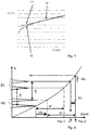
- FIG. 5 is an example of a measurement curve, i.e. a spectrum for methane CH 4 with a lower peak as reference gas and ethane C 2 H 6 as target gas with a higher peak, at a specific target temperature (solid line G 1) and a temperature deviating from the target temperature (dashed line) G 2) shown.
- the deviation of line G 1 from line G 2 is due to a change in the laser temperature and is intended to illustrate the influence of drift on the spacing of the gas peaks.
- the distance error ⁇ I F is shown as an example if a target gas (ethane C 2 H 6 ) is measured at a slightly different laser temperature starting from a reference gas peak (here CH 4 ) with a fixed current distance.
- the temperature reduction results in a shift of the reference gas peak by 0.96 mA. It can be seen that the actual distance between the reference peak and the target gas peak has decreased from 1,669 mA to 1,568 mA. As already mentioned above, this is caused by the non-linear DC tunability of the laser light source. This results in a distance error ⁇ I F of approx. 100 ⁇ A. Applying the proposed method with a fixed temperature change (formula (F 15)) results in a distance error ⁇ I F of only 10 ⁇ A ( Figure 6 ). This means that the target gas signal can be evaluated correctly.
- Figure 6 illustrates the dependence of the distance errors ⁇ I F on the drift values using an example. For various drift values, this shows the distance error ⁇ I F for using a fixed current difference according to formula (F 1) and a fixed temperature difference according to formula (F 15). The values based on the formula F 1 are shown as points P 1 and the values based on the formula F 15 as crosses P 2. It can be seen that with the proposed method, the distance error ⁇ I F of the base current I DC never exceeds 20 ⁇ A, which is sufficiently small to ensure that the measured concentration remains within the specifications.
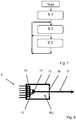
- Figure 7 illustrates a flowchart for fixing the wavelength distance to a reference wavelength.
- a first method step S1 ie when calibrating the measuring system 1, the The basic DC currents of the peak positions of the reference gas and target gas are determined, and secondly the electrical DC power that drops at the internal resistance of the laser is determined for the two peak positions by determining the internal resistance of the laser at the respective current position.
- the power difference ⁇ P DC, cal of the DC powers is determined and stored in the sensor.
- the electrical DC power that drops at the internal resistance of the laser is first determined for the current peak position of the reference gas by measuring the internal resistance using lock-in technology, then the current electrical DC power at the peak position for the target gas by adding the current DC power for the reference gas peak and the DC power difference between the reference gas and the target gas determined during calibration.
- the DC current for its peak position is then determined, the internal resistance of the target gas from one of the preceding measurements being used according to formula F 11 or F 15, the starting value being the value determined during the calibration. If F 15 is used, the ratio of the current laser temperature to the calibration laser temperature is also used. The laser temperature is saved at the time of calibration.
- the actual measurement scan for the target gas is carried out on the basis of the peak position determined for the target gas, and the gas concentration is determined from this.
- the process steps S2 with S3 are preferably carried out several times in a loop, the basic current I DC_ZG for the target gas position being able to be adapted between the process runs if the current basic current I DC_ZG, act from the ideal basic current I DC_ZG.cal , which is used in the calibration of the optical measuring system has been determined.
Landscapes
- Physics & Mathematics (AREA)
- Spectroscopy & Molecular Physics (AREA)
- General Physics & Mathematics (AREA)
- General Health & Medical Sciences (AREA)
- Health & Medical Sciences (AREA)
- Life Sciences & Earth Sciences (AREA)
- Chemical & Material Sciences (AREA)
- Analytical Chemistry (AREA)
- Biochemistry (AREA)
- Immunology (AREA)
- Pathology (AREA)
- Optics & Photonics (AREA)
- Investigating Or Analysing Materials By Optical Means (AREA)
Abstract
Description
- Die Erfindung betrifft ein Verfahren zum Betreiben eines optischen Messsystems zur Messung der Konzentration einer Zielgaskomponente (ZG) in einem Messgas, mit einer Wellenlängen abstimmbaren temperaturstabilisierten Laserlichtquelle, wobei ein zu einer Wellenlänge λZG einer Zielgas-Absorptionslinie korrespondierender aktueller Grundstrom IDC_ZG,act derart eingestellt wird, dass nach einer Kalibrierung der Wellenlängenabstand ΔλDC zwischen der Wellenlänge λZG der Zielgas-Absorptionslinie einer Zielgaskomponente (ZG) und der Wellenlänge λRG einer Referenzgas- Absorptionslinie einer ReferenzgasKomponente (RG) für unterschiedliche Werte des aktuellen Grundstroms IDC_ZG,act der Zielgaskomponente (ZG) und des aktuellen Grundstroms IDC_RG,act der Referenzgaskomponente (RG) aufrecht erhalten wird. Die Erfindung betrifft außerdem eine Anordnung zur Durchführung des Verfahrens.
- Optische Messsysteme zur Messung der Konzentration einer Gaskomponente in einem Messgas, basierend auf der Laser-Absorptionsspektroskopie (LAS) sind aus dem Stand der Technik in vielfältigen Ausführungsformen bekannt, ebenso eine Vielzahl von unterschiedlichen Verfahren zum Betreiben eines solchen optischen Messsystems, wie beispielsweise die Wellenlängen-Modulations-Spektroskopie (WMS) und die direkte Absorptionsspektroskopie (DAS). In der LAS spielen generell die exakte Einstellung der Laser-Wellenlänge auf die Wellenlänge der Absorptionsline des Zielgases eine wichtige Rolle. Üblicherweise wird bei der Kalibrierung die Laser-Wellenlänge über den Arbeitspunkt von Peltiertemperatur (Grund-Lasertemperatur) und des Grundstromes IDC der Laserlichtquelle definiert. Langzeit-Veränderungen des Lasers und äußere Temperatureinflüsse führen jedoch dazu, dass trotz unverändertem Grundstrom IDC eine andere Wellenlänge für den gewählten Arbeitspunkt resultiert, die von der Absorptionswellenlänge des Zielgases abweicht. Mit Grundstrom wird üblicherweise ein Gleichstrom (DC) bezeichnet, bei dem die Absorptionslinie ihr Maximum hat und um den bei Abtastung der Absorptionslinie größere und kleinere Stromwerte durchfahren werden. Als Folge führen diese Veränderungen auch dazu, dass die Sensor-Kalibrierung aus den Spezifikationsgrenzen läuft, was dann oft eine Neukalibrierung des optischen Messsystems erforderlich macht.
- Um die Wellenlänge des Zielgases akkurat zu halten (insbesondere bei Abwesenheit des Zielgases), wird/werden meist eine/mehrere Absorptionsline(n) eines Referenzgases verwendet und das Prinzip des Line-Lockings angewandt. Das Referenzgas ist entweder quasi-permanent im Prozessgas enthalten oder wird beispielsweise in einer Küvette eingeschlossen, irgendwo im Sensor selbst untergebracht. Dabei kann z.B. die Küvette im Mess-Strahlengang oder in einem speziellen Referenzstrahlengang (benötigt einen Strahlteiler und eine weitere Photodiode) implementiert sein.
- Oft ist es nicht möglich oder sinnvoll, das Zielgas selbst als Referenzgas zu verwenden, z.B. wenn dieses nicht langzeitstabil ist, mit diesem eine zu geringe Linienstärke verbunden ist, die aus einer zu kurzen Absorptionsstrecke resultiert und zu einem zu kleinen Absorptionssignal führt, oder zu gefährlich in der Herstellung bzw. im Betrieb ist.
- Alternativ kann an Stelle des Zielgases ein anderes Gas (Referenzgas) verwendet werden, das in der Nähe einer Zielwellenlänge eine oder mehrere Absorptionslinie(n) aufweist. Beispielhaft wird auf die
EP 2 307 876 B1 verwiesen. Bei diesem Patent werden beispielsweise zwei CH4 Gasabsorptionslinien verwendet, um die CO-Gasabsorptionslinie in deren Mitte exakt zu referenzieren. Oft ist jedoch der Tuningbereich der Laserlichtquelle ungenügend breit, um eine Zielgasabsorptionslinie derart akkurat zu referenzieren. - Die
EP 2 307 876 B1 offenbart ein Verfahren zur Detektion mindestens eines Zielgases mittels Laserspektroskopie, mit einer Laserlichtquelle, deren Emissionswellenlänge monochrom und mittels einer Variation der Betriebstemperatur oder des Betriebsstroms abstimmbar ist. Dabei erfolgt zur Kalibrierung der Wellenlängenskala der Laserlichtquelle relativ zur variierten Betriebstemperatur oder zum variierten Betriebsstrom im Wellenlängenbereich einer Bande des mindestens einen Zielgases eine erste Abstimmung der Laserlichtquelle über eine erste Abstimmbreite, wobei mindestens zwei Absorptionslinien eines Referenzgases und mindestens eine Absorptionslinie des mindestens einen Zielgases enthalten sind. Anschließend erfolgt im Wellenlängenbereich der Bande des mindestens einen Zielgases eine zweite Abstimmung der Laserlichtquelle über eine zweite Abstimmbreite, wobei die zweite Abstimmbreite schmaler ist als die erste Abstimmbreite, und wobei mindestens eine der mindestens einen Absorptionslinie des mindestens einen Zielgases enthalten ist. Zielgas und Referenzgas sind unterschiedliche Gase. Hierbei wird die erste Abstimmung zur Kalibrierung des Laserstromes oder der Lasertemperatur mit der absoluten Wellenlängenskala einmalig und die zweite Abstimmung zur Detektion des mindestens einen Zielgases mehrfach hintereinander ausgeführt. Die zweite Abstimmbreite wird mit einem berechneten Absorptionsspektrum verglichen, wobei eine nicht-iterative Kurvenanpassung mit linearem Regressionsalgorithmus angewandt wird, um die Konzentration des mindestens einen Zielgases in einem Schritt zu berechnen. Dieses Vorgehen erfordert ein Referenzgas, das in der Nähe der Zielgasabsorptionslinie mindestens zwei Absorptionslinien aufweist, die im TuningBereich des Lasers liegen. Zudem ist dieses Vorgehen zeitintensiv, da zwei Referenzlinien detektiert und ausgewertet werden müssen. - Aus der
DE 10 2013 202 289 A1 ist zur Ansteuerung einer wellenlängendurchstimmbaren Laserdiode in einem Spektrometer ohne ein Referenzgas bekannt, eine Leistung-Zeit-Funktion vorzugeben, entsprechend der die Laserdiode periodisch über einen Wellenlängenbereich durchgestimmt wird, indem aus der Leistung-Zeit-Funktion und Messwerten der an der Laserdiode anliegenden Spannung ein Stromverlauf ermittelt wird, mit dem die Laserdiode angesteuert wird. Dabei wird der Stromverlauf, mit dem die Laserdiode unmittelbar angesteuert wird, von einer Regeleinrichtung in Abhängigkeit von der Regelabweichung zwischen der Leistungsaufnahme (Ist-Größe) der Laserdiode und der vorgegebenen Leistung-Zeit-Funktion (Soll-Größe) erzeugt, wobei die an der Laserdiode anliegende Spannung und der Strom durch die Laserdiode kontinuierlich erfasst, z. B. gemessen, werden und durch Multiplikation der gemessenen Strom- und Spannungswerte laufend die Leistungsaufnahme der Laserdiode ermittelt wird. Dort wird kein Referenzgas verwendet, so dass sich bei der Änderung der Temperatur des Peltierelements (Peltiertemperatur), auf dem ein Laserchip angeordnet ist, und/oder der Außentemperatur trotz vorgegebener Leistungs-Zeit-Funktion ein anderer Wellenlängenlängenbereich erfasst wird. Für das Referenzieren eines Zielgases ist diese Methode zu ungenau. Zudem wird die gesamte Spannung über dem Laser gemessen, was für die Wellenlängenbestimmung zu ungenau ist. - Liegt bei der Verwendung eines Referenzgases nur eine Referenzgaslinie vor, die nicht die Zielgaslinie ist, so muss unbedingt sichergestellt sein, dass der Wellenlängen-Abstand ΔλDC zwischen Zielgas und Referenzgas im Betrieb für unterschiedliche Laserströme, und damit unterschiedlichen Lasertemperaturen konstant gehalten wird. Zudem muss der Abstand auch unter Alterung des Lasers konstant bleiben. Prinzipiell könnte man einfach einen gewissen Wellenbereich abtasten. Allerdings ist die Nachweisgrenze aufgrund des vorhandenen Rauschens (Noise), resultierend aus z.B. optische Interferenzphänomene sowie das Vorhandensein von Absorptionslinien anderer Gase im gemessenen Spektrum stark begrenzt. Deshalb ist es wichtig, den Wellenlängenabstand sehr genau einzuhalten.
- Typischerweise wird der Wellenlängen-Abstand zwischen Zielgas und Referenzgas durch einen konstanten Strom-Abstand ΔI eingestellt. Durch das nicht-lineare DC-Tuningverhalten des Lasers führt eine Verschiebung (Drift) des Arbeitspunktes, beispielsweise durch den Einfluss der Außentemperatur auf die Temperaturstabilisierung oder der Alterung des Lasers/Elektronik, zu einem Distanzfehler des Wellenlängen-Abstandes. Dies hat zur Folge, dass die Zielgaskomponente (Absorptionslinie des Zielgases) an einem falschen Ort vermutet wird. Daraus ergeben sich u.U. erhebliche Messfehler.
- Davon ausgehend liegt der beanspruchten Erfindung die Aufgabe zugrunde, eine andere genauere, effektive und einfach zu implementierende Möglichkeit vorzuschlagen, den Wellenlängen-Abstand zwischen Ziel- und Referenzgaslinie trotz sich ändernder Lasereigenschaften, z.B. Betriebsstrom, -temperatur, Langzeitdrift, konstant zu halten.
- Diese Aufgabe wird erfindungsgemäß durch ein Verfahren zum Betreiben eines optischen Messsystems zur Messung der Konzentration einer Zielgaskomponente in einem Messgas, mit den Merkmalen des Patentanspruchs 1 sowie durch eine Anordnung in Form eines Messsystems gemäß Anspruch 6 gelöst. Weitere vorteilhafte Ausführungsformen sind den jeweiligen rückbezogenen Unteransprüchen zu entnehmen.
- Der Erfindung liegt der Kerngedanke zugrunde, zur Berechnung der vermuteten Wellenlängen-Position des Zielgases anstatt eines festen Stromdifferenz-Wertes die Stromdifferenz so einzustellen, dass zwischen Referenz- und Zielgas-(peak)position d.h. zwischen den jeweiligen Absorptionslinien, eine vorab definierte Temperaturdifferenz aufrecht erhalten wird. Diese Temperaturdifferenz errechnet sich durch die Differenz der Temperaturen, die durch die jeweilig eingebrachten elektrischen Leistungen an einem Innenwiderstand der Laserlichtquelle an den Peakpositionen von Ziel- und Referenzgas zum Zeitpunkt der Kalibrierung erzeugt werden. Diese Temperaturdifferenz ist proportional zum Wellenlängenabstand der Absorptionslinien von Ziel- und Referenzgas, sodass durch diese Vorgehensweise sichergestellt wird, dass die Zielwellenlänge immer exakt bestimmbar ist.
- Dieses Verfahren ermöglicht vorteilhafterweise zum Beispiel die einfache Realisierung von Anwendungen, bei denen Referenzgas- und Zielgasabsorptionslinien beträchtlich weit auseinanderliegen. Als Beispiel sei hier die Methan-Lecksuche genannt, wo neben CH4 auch C2H6 (Ethan) gemessen werden muss, um sicherzustellen, dass es sich um Erdgas handelt. Als Referenzgas wird Methan verwendet (das in diesem Fall auch gleichzeitig das zweite Zielgas darstellt), welches zu diesem Zweck im Strahlengang des Lasers im Sensor untergebracht wird. Hierbei beträgt der Abstand zwischen Referenzgas (Methan) und Zielgas (Ethan), je nach den gewählten Absoptionslinien zwischen 0,6 und 1,0 nm. Da dieser Abstand beträchtlich ist, kann hier ein fester Stromwert nicht mehr verwendet werden. Ein weiterer Vorteil liegt in der besonders einfachen Kalibrierung im Gegensatz zu den aus dem Stand der Technik bekannten herkömmlichen Kalibrierungsverfahren.
- Die nachfolgend verwendeten Abkürzungen RG bzw. ZG stehen für Referenzgas oder Referenzgaskomponente in einem Gas bzw. für Zielgas oder Zielgaskomponente in einem Messgas. Die benutzten Bezeichnungen DC bzw. AC sind allgemein gebräuchlich und damit dem Fachmann als Bezeichnungen für Gleichspannung/Gleichstrom bzw. Wechselspannung/Wechselstrom bekannt. Sie beziehen sich auf elektrische Ströme, Spannungen und/oder Leistungen, und geben den jeweiligen Typ an. Außerdem wird das Kürzel L für die Laserlichtquelle oder allgemein für Laser verwendet. Die Begriffe RG, ZG, DC, AC bzw. L dienen der Klarstellung in den Patentansprüchen und im allgemeinen Beschreibungsteil, insbesondere in den nachstehenden Formeln. Mit Grundstrom IDC werden zusammenfassend alle den jeweiligen Betriebszuständen (Kalibrierung, aktueller Grundstrom) und zugehörigen Gasen (RG, ZG) entsprechenden Grundstöme bezeichnet. Die Indizes act und cal stehen für den jeweiligen aktuellen Wert bzw. kalibrierten Wert von Strom, Spannung, Temperatur, Innenwiderstand und Leistung.
- Bei dem Verfahren wird erfindungsgemäß im Betrieb eine vorab bei der Kalibrierung definierte Temperaturdifferenz in der Laserlichtquelle, zwischen den zum Zeitpunkt der Kalibrierung gewählten Arbeitspunkten von Referenzsgas (RG), mit einem Grundstrom IDC_RG,cal, und der Zielgaskomponente (ZG), mit einem Grundstrom IDC_ZG,cal, aufrecht erhalten, indem, in Abhängigkeit eines aktuellen Grundstroms IDC_RG,act des Referenzgases, der dafür nötige aktuelle Grundstrom IDC_ZG,act für die Zielgaskomponente bestimmt wird.
- Zur Bestimmung der jeweiligen Größen mit Referenzgas und Zielgas bei der Kalibrierung und der Messung werden die den Gasabsorptionslinien der Referenzgas- RG und der Zielgaskomponente ZG zugeordneten Grundströme IDC_RG,cal und IDC_ZG,cal bzw. IDC_RG,act festgestellt, die zugehörigen elektrischen Leistungen PDC_RG,cal und PDC_ZG,cal bzw. PDC_RG,act unter Berücksichtigung der Innenwiderstände RI_RG,cal und RI_ZG,cal bzw. RI_RG,act der Laserlichtquelle bei diesen Grundströmen bestimmt. Aus PDC RG,cal und PDC ZG,cal wird die Leistungsdifferenz ΔPDC,cal berechnet. Aus PDC RG,act und - der Leistungsdifferenz ΔPDC,cal wird die Leistung PDC ZG,act ermittelt.
- Vorzugsweise wird die Kalibrierung des Messsystems mit Referenzgas und Zielgas durchgeführt. Bei der Kalibrierung werden die den Gasabsorptionslinien der Referenzgas RG und der Zielgaskomponente ZG zugeordneten Grundströme IDC_RG,cal und IDC_ZG,cal festgestellt, die zugehörigen elektrischen Leistungen PDC_RG,cal und PDC_ZG,cal der Laserlichtquelle bestimmt und daraus eine Leistungsdifferenz ΔPDC,cal festgelegt, die abgespeichert wird.
- Erfindungsgemäß wird zudem im Betrieb des Messsystems dann die der Gasabsorptionslinie des Referenzgases zugeordnete elektrische Leistung PDC_RG,act der Laserquelle aus dem aktuellen Grundstrom IDC_RG,act und dem aktuellen Innenwiderstand RI_RG,act ermittelt, indem zur Ermittlung des relevanten Grundstromes ein Strom-Scan über die Gasabsorptionslinie des Referenzgases ausgeführt wird, wobei die Spitzenposition (Peakposition) der Gasabsorptionslinie den aktuellen Grundstrom IDC_RG,act ergibt. Die der Gasabsorptionslinie des Zielgases ZG zugeordnete elektrische Leistung PDC_ZG,act der Laserquelle wird als Summe aus der elektrischen Leistung PDC_RG,act und der Leistungsdifferenz ΔPDC,cal bestimmt, und aus der so bestimmten elektrischen Leistung PDC_ZG,act sowie dem Innenwiderstand RI_ZG,act der Laserquelle der zugeordnete Grundstrom IDC_ZG,act berechnet.
- Mit anderen Worten heißt dies, dass bei der Kalibrierung die DC-Laserströme der Peak-Positionen von Referenzgas und Zielgas festgelegt werden, die elektrische DC-Leistung, die am Innenwiderstand des Lasers abfällt, für die beiden Peak-Positionen ermittelt wird, indem der Innenwiderstand des Lasers an der jeweiligen Stromposition oder alternativ auch eine äquivalente Größe erfasst wird, beispielsweise durch Lock-in-Technik. Der Innenwiderstand wird entweder aus der Strom-Spannungskennlinie der Laserspannung und Grundstrom oder durch Lock-in-Technik (Modulation des Lasers mit einem Strom IAC mit einer Strom-Modulationsamplitude ΔIAC und Messen von UAC sowie anschließendem Bestimmen der ersten Fourierkomponente (1f) des UAC-Signals und Division von UAC,1f durch ΔIAC, wobei ΔIAC auch eine äquivalente Größe sein kann) ermittelt. Zum Zeitpunkt der Kalibrierung wird die Leistungsdifferenz ΔPDC,cal der DC-Leistungen oder mindestens eine äquivalente Größe ermittelt und im Sensor abgespeichert. Die Bestimmung der Leistungsdifferenz erfolgt vorzugsweise nach der nachfolgend aufgeführten Formel F 10. Alternativ können auch die in Formel F 10 angegebenen Größen im Sensor abgespeichert werden.
- Im Betrieb des Messsystems wird die elektrische DC-Leistung, die am Innenwiderstand des Lasers abfällt, für die aktuelle Peakposition des Referenzgases bestimmt. Die Innenwiderstandsmessung kann insbesondere durch Lock-in-Technik realisiert werden. Da Drift den Arbeitspunkt verschieben kann wird die elektrische Leistung PDC_RG,act regelmäßig neu berechnet (kann also nicht als fixer Wert angenommen werden). Des Weiteren wird die aktuelle elektrische Leistung an der Peakposition für das Zielgas durch Addition der aktuellen Leistung für den Referenzgaspeak und der Leistungsdifferenz bestimmt. Aus der aktuellen Leistung des Peaks für das Zielgas wird der DC-Strom für dessen Peakposition vorzugsweise gemäß nach der nachfolgend aufgeführten Formel F 11 ermittelt. Anschließend wird an der ermittelten Peakposition für das Zielgas der Mess-Scan für das Zielgas durchgeführt und hieraus die Gaskonzentration ermittelt. Der Grundstrom definiert die Position, bei der die Absorptionskennlinie ein Maximum hat. Um dieses Maximum herum wird eine Abtastung mit größeren und kleineren Stromwerten durchgeführt, um die Konzentration zu ermitteln.
- Das vorgeschlagene Verfahren wird für die Erstkalibrierung des Messsystems durch den Hersteller genutzt und kann auch vom Anwender für eine eventuell nötige Nachkalibrierung eingesetzt werden.
- Bei der Wellenlängen-Modulationsspektroskopie wird wie üblich eine wellenlängenabstimmbare temperaturstabilisierte Laserlichtquelle verwendet, welche eine zentrale Basiswellenlänge des Laserlichts der Laserlichtquelle periodisch durch Änderung des Grundstroms über eine interessierende Absorptionslinie der Gaskomponente an einem Arbeitspunkt variiert und gleichzeitig mit einer Frequenz (f) und einer bestimmbaren Amplitude mittels einer Modulationseinrichtung Wellenlängen-moduliert. Mit einem Lichtdetektor wird die Intensität des Laserlichtes nach dem Durchtritt durch das Messgas detektiert. Es wird eine Auswerteeinrichtung benutzt, die Mittel zur phasensensitiven Demodulation eines von dem Lichtdetektor erzeugten Messsignals bei der Frequenz (f) und/oder einer ihrer Harmonischen enthält, wobei die Laserlichtquelle mit einem Grundstrom IDC und einem Modulationsstrom IAC strommoduliert betrieben wird und einen Laserstrahl der Wellenlänge mit einer Wellenlängen-Modulationsamplitude ΔλAC emittiert und die Wellenlängen-Modulationsamplitude ΔλAC des Laserlichtes über eine variable Einstellung der Strom-Modulationsamplitude ΔIAC konstant gehalten wird.
- Langzeit-Veränderungen des Lasers können dazu führen, dass es nötig wird, die Grund-Lasertemperatur anzupassen. Hierbei ist jedoch auch eine Korrektur der zuvor berechneten Leistungsdifferenz ΔPDC,cal nötig. Wird die Lasertemperatur verändert, so ist Formel F 15 der Formel F 11 für die Berechnung des Grundstroms IDC_ZG,act vorzuziehen. Hierfür wird zum Zeitpunkt der Kalibrierung die Lasertemperatur abgespeichert.
- Gemäß eines bevorzugten Verfahrensschritts werden für die Berechnung der elektrischen Leistung an den jeweiligen Grundströmen (für Ziel- und Referenzgas) die jeweiligen Innenwiderstände benötigt. Hierbei ist zu beachten, dass der exakte Innenwiderstand u.U. erst nach mehreren Messungen iteriert. Für die Iteration werden Widerstandswerte aus einer der vorhergehenden Messungen verwendet, wobei als anfänglicher Startwert der bei der Kalibrierung ermittelte Wert verwendet werden kann. Grundsätzlich kann auch ein auf Erfahrung basierender Schätzwert verwendet werden.
- Vorzugsweise wird der Innenwiderstand RI der Laserlichtquelle aus einer Spannung-Strom-Kennlinie der Laserlichtquelle bestimmt, bei der der Spannungsabfall UL an der Laserlichtquelle abhängig von dem Grundstrom IDC aufgenommen ist. Die jeweiligen Innenwiderstände werden bei der Peakposition von Referenzgas und Zielgas ermittelt. Die Spannung-Strom-Kennlinie der Laserlichtquelle wird üblicherweise erstmals bei der Kalibrierung des optischen Messsystems aufgenommen. Es ist dabei nicht erforderlich die gesamte Kurve zu messen, sondern nur in einem Bereich um den Arbeitspunkt herum, um aus der Steigung in diesem Bereich den jeweiligen Innenwiderstand RI korrekt, zu bestimmen. Dabei können in dem Bereich eine Vielzahl von Messungen durchgeführt und das Ergebnis gemittelt werden. Alternativ kann die Steigung auch mittels Lock-in-Technik ermittelt werden mit dem Vorteil, dass eine Rauschreduzierung erreicht wird. Die Ermittlung der Widerstandwerte erfolgt regelmäßig auch beim Betrieb, vorzugsweise werden diese bei jeder Konzentrationsmessung neu bestimmt.
- Bei der Kalibrierung und im regulären Betrieb des optischen Messsystems wird zur Konzentrationsbestimmung einer Zielgaskomponente vorzugsweise eine Auswerteeinrichtung mit Lock-in-Technik verwendet, um in bekannter Art und Weise eine Rauschreduzierung zu erreichen, um insbesondere das vom 1/f-Signal bedingte Rauschen deutlich zu mindern. Bei einem Lock-in-Verstärker, der auch manchmal als phasenempfindlicher Gleichrichter oder Trägerfrequenzverstärker bezeichnet wird, handelt es sich um einen Verstärker zur Messung eines schwachen elektrischen Wechselsignals, das mit einem in Frequenz und Phase bekannten Referenzsignal moduliert ist. Das Gerät stellt einen extrem schmalbandigen Bandpassfilter dar und verbessert dadurch das Signal-RauschVerhältnis. Der Vorteil beim Einsatz eines solchen Gerätes liegt darin, dass Gleichspannungen und Wechselspannungen anderer Frequenz und Rauschen effizient gefiltert werden.
- Das vorstehend beschriebene Verfahren basiert erfindungsgemäß auf den nachfolgend stehenden Formeln. Diese werden bei der Kalibrierung und oder im Betrieb verwendet. Werte aus der Kalibrierung sind mit "cal" und Werte aus dem Betrieb mit "act" gekennzeichnet.
- Bisher wird die aktuelle Strom-Position des Zielgases (ZG) relativ durch die Position des Referenzgases (RG) durch folgende Formel bestimmt:


- Aufgrund des oben erwähnten nicht-linearen DC-Tuningverhaltens des Lasers ist dieses Vorgehen zur Bestimmung der Position des ZG ist nicht genau genug. Aus


- Zur Berechnung der vermuteten Position des Zielgases wird anstelle eines festen Stromdifferenz-Wertes (der bei der Kalibrierung nach Formel F 2 bestimmt wurde) die Stromdifferenz im laufenden Betrieb derart eingestellt, dass zwischen Referenz- und Zielgas(peak)position eine definierte Temperaturdifferenz ΔTact aufrechterhalten wird. Somit ergibt sich folgende Temperatur an der aktuellen Position des Zielgases:


- Die aktuelle Temperatur TZG,act an der Position des Zielgas-Peaks ist dabei mit dem gesuchten Laserstrom IDC_ZG,act über den thermischen und elektrischen Widerstand gekoppelt:

- Bei sich während des Betriebes nicht ändernder Lasertemperatur gilt:

- Die erwähnte Temperaturdifferenz ΔTcal errechnet sich als Differenz der Temperaturen, die durch die jeweilig eingebrachten elektrischen Leistungen am Innenwiderstand an den Peakpositionen von Ziel- und Referenzgas zum Zeitpunkt der Kalibrierung erzeugt werden. Da die Temperaturdifferenz proportional zur Wellenlängendifferenz zwischen ZG und RG ist, wird durch dieses Vorgehen sichergestellt, dass die Zielwellenlänge immer genau bestimmt wird.
- Durch einsetzen der Formeln (F 6), (F 7) und (F 8) in Formel (F 5) ergibt der gesuchte Laserstrom an der Position des Zielgases:


- Unter der Annahme, dass sich der thermische Widerstand während des Betriebes nicht ändert (Rth,act = Rth,cal ) ergibt sich für die Peakposition des Zielgases:
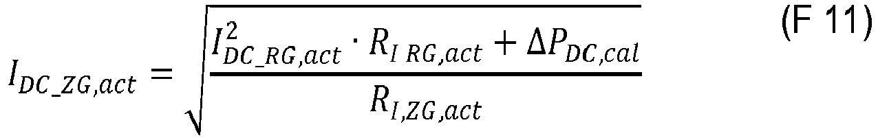
- Formel (F11) kann auch wie folgt geschrieben werden:
- Hierbei ist zu bemerken, dass der exakte Innenwiderstand RIZG,act zunächst nicht bekannt ist (da er ja an der Stelle IDC_ZG,act) gemessen werden müsste. Nach mehrmaligem Durchlaufen der Formel oder nach mehreren Messungen iteriert der Wert jedoch sehr schnell und der Innenwiderstand RIZG,act wird korrekt an der Stelle IDC_ZG,act ermittelt.
- Ändert sich zusätzlich der Arbeitspunkt der Grund-Lasertemperatur TL (z.B. wird die Peltiertemperatur während des Betriebes angepasst, um zu große Wellenlängenverschiebungen auf der Stromskala durch Anpassung der Grund-Laser-Temperatur zu kompensieren), so ergibt sich aus der Temperaturänderungsbedingung:


- Kann eine Änderung des thermischen Widerstandes vernachlässigt werden, so ergibt sich wiederum:

- Es ist allgemein bekannt, dass jedes Laserlichtquellen-Schaltbild durch ein Ersatzschaltbild ersetzt werden kann, das einen Laseremitter (aktive Zone) und einen dazu in Serie geschalteten Innenwiderstand RI umfasst. Sobald durch die Laserlichtquelle ein Grundstrom IDC fließt, liegt an der Laserlichtquelle eine Spannung UL an, die zum Teil am Laseremitter als Teilspannung UE und an dem Innenwiderstand RI als Teilspannung URI abfällt, wobei UE je nach Lasertyp (mit Telekom-naher Wellenlänge) einen Wert von typisch 0.9 - 1.1 V aufweist. Im Falle von WMS wird zusätzlich ein Modulationsstrom IAC zum Grundstrom addiert, welcher jedoch auf dieses Verfahren keine Auswirkungen hat, da sich die Temperaturänderungen zeitlich herausmitteln.
- Die aktuelle DC-Leistung an der Position des Referenzgas-Peaks errechnet sich aus dem Grundstrom IDC_RG,act der durch die Laserlichtquelle fließt und dem am Innenwiderstand RI_RG,act auftretenden Spannungsabfall URI_RG,act als

- Die Kalibrierung des optischen Messsystems erfolgt weitgehend nach der üblichen dem Fachmann geläufigen Methode mittels eines bekannten Referenzgases, das auch ein Zielgas sein kann und dem eigentlichen Zielgas selbst. Zunächst wird für die Festlegung des Arbeitspunktes der Laserlichtquelle die Temperatur der temperaturstabilisierten Laserlichtquelle solange verändert, bis die Absorptionssignale für das Referenz- und Zielgas an einem gewünschten Arbeitspunkt detektiert werden. Anschließend wird die Leistungsdifferenz ermittelt und abgespeichert.
- Die erfindungsgemäße Anordnung besteht aus einem Messsystem zur Durchführung des Verfahrens mit einer Modulationseinrichtung (4) zur Bereitstellung des Grundstromes IDC für die Laserlichtquelle, einer Aufnahme für das Messgas und einem Lichtdetektor sowie einer mit dem Lichtdetektor und der Modulationseinrichtung verbundenen Auswerteeinheit (6), Mittel zur Erfassung der an der Laserlichtquelle anliegenden Spannung, Mittel zur Erfassung der Lasergrundtemperatur, Mittel zur Ermittlung des Innenwiderstandes der Laserlichtquelle sowie Mittel zur Steuerung der Grundströme IDC für Referenzgas (RG) und Zielgas (ZG). Besonders bevorzugt ist das Referenzgas im Strahlengang des Lasers im Sensor angeordnet, so dass der von der Laserlichtquelle emittierte Laserstrahl zuerst durch das Referenzgas und anschließend durch das Messgas zum Lichtdetektor gelangt. Dies ermöglicht eine äußerst kompakten Aufbau des gesamten Messsystems und die Herstellung von einfach zu handhabenden und zu transportierenden Gasdetektionseinrichtungen.
- Die vorstehend in der Beschreibung genannten Merkmale und Merkmalskombinationen sowie die nachfolgend in der Figurenbeschreibung genannten und/oder in den Figuren alleine gezeigten Merkmale und Merkmalskombinationen sind nicht nur in der jeweils angegebenen Kombination, sondern auch in anderen Kombinationen oder in Alleinstellung verwendbar. Zur Ausführung der Erfindung müssen nicht alle Merkmale des Anspruchs 1 oder 6 verwirklicht sein. Auch können einzelne Merkmale der unabhängigen oder nebengeordneten Ansprüche durch andere offenbarte Merkmale oder Merkmalskombinationen ersetzt werden.
- Nachfolgend wird die Erfindung an Hand der beigefügten Zeichnungen nochmals näher erläutert. Es zeigen in schematischer Darstellung:
- Figur 1
- ein für die Durchführung des erfindungsgemäßen Verfahrens geeignetes optisches Messsystem;
- Figur 2
- das Ersatzschaltbild für die Laserlichtquelle;
- Figur 3
- eine aufgenommene Spannungs-Strom-Kennlinie zur Bestimmung des Innenwiderstandes der Laserlichtquelle;
- Figur 4
- die Wellenlänge λI als Funktion des Stromes mit einer schematischen Darstellung der Zielgas-Position und der Referenzgas-Position mit festem Stromabstand zwischen vom Referenzgas-Peak und dem Zielgas-Peak, bei einer bestimmten Temperatur und deren Verschiebung durch Temperaturdrift;
- Figur 5
- eine Messkurve für Methan als Referenzgas, gleichzeitig auch ein weiteres Zielgas und Ethan als Zielgas, bei der Zieltemperatur (durchgezogene Linie) und nach dem Drift (gestrichelte Linie) durch Änderung der Lasertemperatur;
- Figur 6
- der Distanzfehler zum Zielgaspeak gegenüber der Drift des Referenzgaspeaks, gemessen mit fester Stromdifferenz und fester Temperaturdifferenz an einem Beispiel; und
- Figur 7
- ein Ablaufschema für die Fixierung des Wellenlängen-Abstandes zu einer Referenzwellenlänge.
- Die
Figur 1 zeigt schematisch den prinzipiellen Aufbau eines optischen Messsystems 1 zur Messung der Konzentration einer Zielgaskomponente ZG in einem Messgas 2, basierend auf der Wellenlängen-Modulationsspektroskopie (WMS). Das Messsystem 1 weist eine wellenlängenabstimmbare temperaturstabilisierte Laserlichtquelle 3, eine Modulationseinrichtung 4, einen Lichtdetektor 5, und eine elektronische Auswerteeinrichtung 6 auf. Die Laserlichtquelle 3 emittiert einen Laserstrahl 7 mit einer Wellenlänge λDC mit einer Wellenlängen-Modulationsamplitude ΔλAC. Die Modulationseinrichtung 4 variiert die Wellenlänge des Laserlichts der Laserlichtquelle 3 periodisch über Referenzgasabsorptionsline und Zielgasabsorptionslinie an einem Arbeitspunkt und moduliert diese zudem gleichzeitig dreiecksförmig mit einer Frequenz (f) und einer einstellbaren Amplitude. Sie beinhaltet zudem mindestens eine DC- und/oder AC-Spannungsquelle oder eine DC- und AC-Stromquelle 4a und zugeordnete Modulationsmittel 4b zum Betrieb der Laserlichtquelle 3. Damit kann der jeweilige Grundstrom IDC und der Modulationsstrom IAC variabel eingestellt werden. Die Modulationseinrichtung 4 ist direkt mit der Laserlichtquelle 3 verbunden. Der Lichtdetektor 5 erfasst den von der Laserlichtquelle 3 ausgehenden Laserstrahl 7, nachdem dieser das in einer Messkammer 11 befindliche Messgas 2 passiert hat, und erzeugt ein Empfangssignal, das von der Intensität des Laserlichtes nach dem Durchtritt durch das Messgas 2 abhängig ist und der Auswerteinheit 6 zugeführt wird. Die Auswerteinheit 6 umfasst Mittel zur phasensensitiven Demodulation eines von dem Lichtdetektor 5 erzeugten Messsignals bei der Frequenz (f) und/oder einer ihrer Harmonischen. Die Auswerteinheit 6 weist zwei Lock-in-Verstärker 6a, 6b und eine Recheneinheit 6c auf. Die Recheneinheit 6c wertet das demodulierte Empfangssignal des Lichtdetektors 5 aus. Des Weiteren führt eine elektrische Verbindungsleitung 9 zu dem Lock-in-Verstärker 6b, mit der die an der Laserlichtquelle 3 anliegende Spannung erfasst und der Innenwiderstand bestimmt wird. Davon abhängig werden die Grundströme IDC und Modulationsströme für Referenz- und Zielgas mittels der Modulationseinrichtung 4 gesteuert, um den Wellenlängenabstand zwischen Referenz- und Zielgas konstant zu halten. Dazu sindelektrische Steuerleitungen 8 und 10 von der Auswerteinheit 6 zu der Modulationseinrichtung 4 vorgesehen. Bei der Auswertung werden unter anderem primär die vorstehend aufgeführten Formeln F 11 oder F 15 zusammen mit F 10 verwendet. Über die Leitung 12 wird die Peltiertemperatur zu der Auswerteinheit 6 übertragen. Bei der Kalibrierung ist in diesem Ausführungsbeispiel das Referenzgas RG permanent im Strahlengang vorhanden. Die Zielgaskomponente ZG wird dann in die Messgaskammer 11 eingeleitet. - Die
Figur 2 stellt das Ersatzschaltbild für die Laserlichtquelle 3 dar. Die Laserlichtquelle 3 kann demnach durch einen Lichtemitter 3a und einen dazu seriell angeordneten Innenwiderstand RI, 3b rechnerisch ersetzt werden. Die Laserlichtquelle 3 wird mit einem Grundstrom IDC und einem Modulationsstrom IAC strommoduliert betrieben. An der Laserlichtquelle 3 liegt Spannung UL an, die jeweils teilweise an dem Innenwiderstand 3b als Teilspannung URI und am Lichtemitter 3a als Teilspannung UE abfällt. - Die
Figur 3 veranschaulicht eine bei der Kalibrierung des optischen Messsystems 1 aufgenommene Strom/Spannungskennlinie 10 zur Bestimmung des Innenwiderstandes RI RG der Laserlichtquelle 3 am Ort des Referenzgases. Der Innenwiderstand RI RG wird aus der Beziehung der Strom-Spannungs-Charakteristik der Laserlichtquelle 3 im Arbeitspunkt 12 IDC_RG,cal für RG bestimmt. Dazu ist die Strom-Spannungs-Kennlinie 10 (durchgezogene Linie) mit linearer Approximationslinie 11 (gestrichelte Linie) im Arbeitspunkt 12 zur Bestimmung des Innenwiderstandes RI RG am Ort des Referenzgases versehen. Die Steigung der Approximationslinie 11 entspricht dem Innenwiderstande RI, 3b am Arbeitspunkt 12 mit RI RG. Analoges Vorgehen wird am Ort des Zielgases zur Ermittlung von RI ZG angewendet. - Die
Figur 4 verbildlicht in schematischer Darstellung beispielhaft die Wellenlängen-Position eines Zielgases und die eines Referenzgases bei einer bestimmten Ziel-Temperatur, wobei die beiden Positionen zueinander einen definierten Wellenlängenabstand ΔλDC aufweisen, der über die DC-Tunability-Kurve zu einem Stromabstand ΔI führt. Die Absorptionslinien sind für die Ziel-Temperatur durchgezogenen und für einen durch reduzierte Ziel-Temperatur induzierten Drift gestrichelt dargestellt. Typischerweise wird der Wellenlängen-Abstand ΔλDC durch einen konstanten Strom-Abstand ΔI eingestellt. Durch das nicht-lineare DC-Tuningverhalten des Lasers führt eine Verschiebung (Drift) des Arbeitspunktes, beispielsweise durch Einfluss der Außentemperatur des Sensors auf die Temperaturstabilisierung oder der Alterung des Lasers/Elektronik zu einem Distanzfehler AIF für die Position des Gaspeaks des Zielgases GZ, sodass daraus Messfehler resultieren. Die Figur zeigt schematisch die Position des Referenz- und des Zielgases zum Zeitpunkt der Kalibrierung. Durch Drift wird die Position der Referenzgaslinie verschoben. Aufgrund des nichtlinearen Zusammenhangs zwischen Wellenlänge und Laserstroms ergibt sich bei einer festen Stromdistanz ΔI eine Differenz, d.h. ein falsche Wellenlänge mit einem Wellenlängendistanz-Fehler ΔλF, d.h. ein Distanzfehler zwischen dem berechneten und der tatsächlichen Zielgas-Position. Im günstigsten Fall ist der Fehler klein (typ. <20 µA) und der Sensor ist immer noch innerhalb seiner Spezifikationen bezüglich Genauigkeit der Konzentration. Wird der Fehler grösser, steigt der Fehler überlinear an. Im Extremfall wird der Peak nicht einmal mehr im Tuningbereich liegen (inFig 4 wird beispielsweise das Zielgas gar nicht mehr gemessen). Je grösser der Abstand zwischen Referenz- und Zielgas ist, desto geringer muss nach dieser Methode der erlaubte Drift sein, andernfalls ist der Distanzfehler >20 µA. An Pos.1 liegt die tatsächliche Zielgas-Position (zugehöriger Grundstrom) und an Pos.2 die über die Formeln F 1 bis F 2 berechnete Zielgas-Position (zugehöriger Grundstrom). Diese beiden Zielgas-Positionen weichen um den Distanzfehler ΔIF voneinander ab. Zu beachten ist, dass die DC-Tunability-Kurve selbst unbeeinträchtigt durch einen Drift gezeichnet ist. In der Realität kann sich auch die DC-Tunability-Kurve selbst mit einem Langzeitdrift ändern. - In der
Figur 5 ist beispielhaft eine Messkurve, d.h. ein Spektrum für Methan CH4 mit einer niedrigeren Spitze als Referenzgas und Ethan C2H6 als Zielgas mit einer höheren Spitze, bei einer bestimmten Zieltemperatur (durchgezogene Linie G 1) und von der Zieltemperatur abweichenden Temperatur (gestrichelte Linie G 2) dargestellt. Die Abweichung der Linie G 1 von der Linie G 2 ist durch eine Änderung der Lasertemperatur bedingt und soll den Einfluss von Drift auf den Abstand der Gaspeaks veranschaulichen. Beispielhaft wird gezeigt, welcher Distanzfehler ΔIF resultiert, wenn von einem Referenzgaspeak ausgehend (hier CH4) mit fester Stromdistanz ein Zielgas (Ethan C2H6) bei geringfügig unterschiedlicher Lasertemperatur gemessen wird. Durch die Temperaturreduktion ergibt sich eine Verschiebung des Referenzgaspeaks um 0.96 mA. Es ist zu erkennen, dass der tatsächliche Abstand von Referenzpeak und Zielgaspeak von 1.669 mA auf 1.568 mA abgenommen hat. Wie bereits vorstehend erwähnt, ist dies durch die nicht-lineare DC-Tunability der Laserlichtquelle hervorgerufen. Es ergibt sich somit ein DistanzfehlerΔIF von ca. 100 µA. Wendet man die vorgeschlagene Methode mit fester Temperaturänderung an (Formel (F 15)), so ergibt sich ein Distanzfehler ΔIF von nur 10 µA (Figur 6 ). Dies führt dazu, dass das Zielgassignal korrekt ausgewertet werden kann. -
Figur 6 verdeutlicht die Abhängigkeit der Distanzfehler ΔIF von den Driftwerten an Hand eines Beispiels. Dieses zeigt für verschiedene Driftwerte den Distanzfehler ΔIF für die Verwendung einer festen Stromdifferenz nach Formel (F 1) und fester Temperaturdifferenz nach Formel (F 15). Die Werte basierend auf der Formel F 1 sind als Punkte P 1 und die Werte basierend auf Formel F 15 als Kreuze P 2 dargestellt. Es ist zu erkennen, dass mit der vorgeschlagenen Methode der Distanzfehler ΔIF des Grundstromes IDC nie grösser als 20 µA wird, was genügend klein ist, um sicherzustellen, dass die gemessene Konzentration innerhalb der Spezifikationen bleibt. -
Figur 7 veranschaulicht ein Ablaufschema für die Fixierung des Wellenlängen-Abstandes zu einer Referenzwellenlänge. Dabei werden in einem ersten Verfahrensschritt S1, d.h. bei der Kalibrierung des Messsystems 1, zum Einen die DC-Grundströme der Peak-Positionen von Referenzgas und Zielgas festgelegt und zum Zweiten die elektrische DC-Leistung, die am Innenwiderstand des Lasers abfällt, wird für die beiden Peak-Positionen ermittelt, indem der Innenwiderstand des Lasers an der jeweiligen Stromposition bestimmt wird. Zum Dritten wird die Leistungsdifferenz ΔPDC,cal der DC-Leistungen ermittelt und im Sensor abgespeichert. - In dem darauf folgenden zweiten Verfahrensschritt S2, d.h. beim Betrieb des Messsystem 1, wird zunächst die elektrische DC-Leistung, die am Innenwiderstand des Lasers abfällt, für die aktuelle Peakposition des Referenzgases durch das Messen des Innenwiderstandes durch Lock-in-Technik bestimmt, dann die aktuelle elektrische DC-Leistung an der Peakposition für das Zielgas durch Addition der aktuellen DC-Leistung für den Referenzgaspeak und der bei der Kalibrierung ermittelten DC-Leistungsdifferenz zwischen dem Referenzgas und dem Zielgas berechnet. Anschließend wird der DC-Strom für dessen Peakposition ermittelt, wobei hierfür nach Formel F 11 oder F 15 der Innenwiderstand des Zielgases aus einer der vorhergehenden Messung Verwendung findet, wobei der Startwert der bei der Kalibrierung ermittelte Wert ist. Im Falle von Verwendung von F 15 wird zusätzlich das Verhältnis der aktuellen Lasertemperatur zur Kalibrier-Lasertemperatur verwendet. Zum Zeitpunkt der Kalibrierung wird die Lasertemperatur abgespeichert.
- In dem anschließenden dritten Verfahrensschritt S3 wird anhand der ermittelten Peakposition für das Zielgas der eigentliche Mess-Scan für das Zielgas durchgeführt und hieraus die Gaskonzentration ermittelt.
- Die Verfahrensschritte S2 mit S3 werden vorzugsweise in einer Schleife mehrfach ausgeführt, wobei zwischen den Verfahrensdurchläufen der Grundstrom IDC_ZG für die Zielgas Position angepasst werden kann, wenn der aktuelle Grundstrom IDC_ZG,act von dem idealen Grundstrom IDC_ZG.cal, der bei der Kalibrierung des optischen Messsystems ermittelt worden ist, abweicht.
Claims (6)
- Verfahren zum Betreiben eines optischen Messsystems (1) mit einer Wellenlängen abstimmbaren temperaturstabilisierten Laserlichtquelle (3) zur Messung der Konzentration einer Zielgaskomponente (ZG) in einem Messgas (2), wobei ein zu einer Wellenlänge λZG einer Zielgas-Absorptionslinie korrespondierende aktuelle Grundstrom IDC_ZG,act derart eingestellt wird, dass nach einer Kalibrierung der Wellenlängenabstand ΔλDC zwischen der Wellenlänge λZG der Zielgas-Absorptionslinie einer Zielgaskomponente (ZG) und der Wellenlänge λRG einer Referenzgas-Absorptionslinie einer Referenzgaskomponente (RG) für beliebige Werte des aktuellen Grundstroms IDC_ZG,act der Zielgaskomponente (ZG) und des aktuellen Grundstroms IDC_RG,act der Referenzgaskomponente (RG) aufrecht erhalten wird, dadurch gekennzeichnet, dass
im Betrieb eine vorab bei der Kalibrierung definierte Temperaturdifferenz in der Laserlichtquelle (3), zwischen den zum Zeitpunkt der Kalibrierung gewählten Arbeitspunkten von Referenzgas (RG), mit einem bei der Kalibrierung ermittelten Grundstrom IDC_RG,cal, und Zielgas (ZG), mit einem bei der Kalibrierung ermittelten Grundstrom IDC_ZG,cal, aufrecht erhalten wird, indem, in Abhängigkeit des aktuellen Grundstroms IDC_RG,act des Referenzgases (RG), der dafür nötige aktuelle Grundstrom IDC_ZG,act für das Zielgas (ZG) bestimmt wird. - Verfahren nach Anspruch 1, dadurch gekennzeichnet, dass
die Kalibrierung des Messsystems (1) mit einem Referenzgas und einem Zielgas durchgeführt wird und bei der Kalibrierung
die den Gasabsorptionslinien des Referenzgases (RG) und des Zielgases (ZG) zugeordneten Grundströme IDC_RG,cal und IDC_ZG,cal festgestellt werden, und
die zugehörigen elektrischen Leistungen PDC_RG,cal und PDC_ZG,cal der Laserlichtquelle (3) aus den Grundströmen IDC_RG,cal und IDC_ZG,cal sowie den zugehörigen Innenwiderständen RI_RG,cal und RI_ZG,cal bestimmt werden und daraus eine Leistungsdifferenz ΔPDC,cal festgelegt und diese und/oder eine oder mehrere äquivalente Größe/n im Messsystem (1) abgespeichert wird,
und dass beim Betrieb des Messsystems (1)
die der Gasabsorptionslinie des Referenzgases zugeordnete aktuelle elektrische Leistung PDC_RG,act der Laserquelle (3) aus dem aktuellen Grundstrom IDC_RG,act und dem aktuellen Innenwiderstand RI_RG,act ermittelt wird,
die der Gasabsorptionslinie des Zielgases zugeordnete aktuellen elektrische Leistung PDC_ZG,act der Laserquelle (3) als Summe aus der aktuellen elektrischen Leistung PDC_RG,act und der Leistungsdifferenz ΔPDC,cal bestimmt wird, und aus der so bestimmten aktuellen elektrischen Leistung PDC_ZG,act der Laserquelle (3) der zugeordnete aktuelle Grundstrom IDC_ZG,act unter Berücksichtigung des aktuellen Innenwiderstand RI_RG,act berechnet wird. - Verfahren nach Anspruch 2, dadurch gekennzeichnet, dass im Betrieb die Messung der Konzentration des Zielgases (ZG) mit dem zuvor aus der Leistung PDC_RG,act, der Leistungsdifferenz ΔPDC,cal und dem Innenwiderstand RI_ZG,act berechneten Grundstrom IDC_ZG,cal durchgeführt und daraus die Gaskonzentration des Zielgases (ZG) in dem Messgas (2) ermittelt wird.
- Verfahren nach Anspruch 2 oder 3, dadurch gekennzeichnet, dass beim Betrieb des Messsystems (1) Änderungen einer Grund-Lasertemperatur TL,cal der Laserlichtquelle (3) durch Anpassung des Leistungsdifferenz ΔPDC,cal berücksichtigt werden.
- Verfahren nach einem der vorstehenden Ansprüche, dadurch gekennzeichnet, dass der Innenwiderstand RI (3b) der Laserlichtquelle (3) von Referenzgas und Zielgas aus der jeweiligen zum aktuellen Grundstrom IDC_RG,act bzw. IDC_ZG,act gehörenden Steigung einer Spannung-Strom-Kennlinie der Laserlichtquelle (3) bestimmt wird.
- Messsystem (1) mit einer Wellenlängen abstimmbaren temperaturstabilisierten Laserlichtquelle (3) zur Durchführung des Verfahrens nach einem der Ansprüche 1 bis 5, mit einer Modulationseinrichtung (4) zur Bereitstellung des Grundstromes IDC und eines Modulationsstromes IAC für die Laserlichtquelle (3), einem Messgas (2) und einem Lichtdetektor (5) sowie einer mit dem Lichtdetektor (5) und der Modulationseinrichtung (4) verbundenen Auswerteeinheit (6), Mittel (9; 6) zur Erfassung der an der Laserlichtquelle anliegenden Spannung, Mittel (12, 6) zur Erfassung der Lasergrundtemperatur, Mittel (6) zur Ermittlung des Innenwiderstandes der Laserlichtquelle (3) sowie Mittel (10, 6) zur Steuerung der Grundströme IDC für Referenzgas (RG) und Zielgas (ZG), wobei die Laserlichtquelle (3) einen Laserstrahl (7) mit einer Wellenlänge λDC mit einer Wellenlängen-Modulationsamplitude ΔλAC emittiert und die Modulationseinrichtung (4) die Wellenlänge des Laserlichts der Laserlichtquelle (3) periodisch über die Absorptionslinie des Referenzgases (RG) und der Absorptionslinie des Zielgases (ZG) an einem Arbeitspunkt variiert und diese gleichzeitig mit einer Frequenz (f) und einer einstellbaren Amplitude moduliert, die Modulationseinrichtung (4) direkt mit der Laserlichtquelle (3) verbunden ist, der Lichtdetektor (5) den von der Laserlichtquelle (3) ausgehenden Laserstrahl (7) erfasst, nachdem dieser das Messgas (2) passiert hat, und ein Empfangssignal erzeugt, das von der Intensität des Laserlichtes nach dem Durchtritt durch das Messgas (2) abhängig ist, welches der Auswerteinheit (6) zugeführt wird, und wobei die Mittel (9; 6) zur Erfassung der an der Laserlichtquelle anliegenden Spannung, die Mittel (12, 6) zur Erfassung der Lasergrundtemperatur, die Mittel (6) zur Ermittlung des Innenwiderstandes der Laserlichtquelle (3) sowie die Mittel (10, 6) zur Steuerung der Grundströme IDC für Referenzgas (RG) und Zielgas (ZG) zusammenwirken, um die an der Laserlichtquelle (3) anliegende Spannung zu erfassen und den Innenwiderstand zu bestimmen, und davon abhängig die Grundströme IDC für Referenzgas (RG) und Zielgas (ZG) mittels der Modulationseinrichtung (4) zu steuern, um den Wellenlängenabstand zwischen Referenzgas (RG) und Zielgas (ZG) konstant zu halten.
Priority Applications (1)
| Application Number | Priority Date | Filing Date | Title |
|---|---|---|---|
| CN201910916414.1A CN110987867B (zh) | 2018-10-02 | 2019-09-26 | 用于激光光谱学的光学测量系统中的目标气体的相对定位的方法和系统 |
Applications Claiming Priority (1)
| Application Number | Priority Date | Filing Date | Title |
|---|---|---|---|
| EP18198084 | 2018-10-02 |
Publications (2)
| Publication Number | Publication Date |
|---|---|
| EP3633352A1 true EP3633352A1 (de) | 2020-04-08 |
| EP3633352B1 EP3633352B1 (de) | 2020-12-30 |
Family
ID=63722168
Family Applications (1)
| Application Number | Title | Priority Date | Filing Date |
|---|---|---|---|
| EP19160093.1A Active EP3633352B1 (de) | 2018-10-02 | 2019-02-28 | Verfahren und anordnung zum relativen referenzieren eines zielgases in einem optischen messsystem für die laserspektroskopie |
Country Status (2)
| Country | Link |
|---|---|
| EP (1) | EP3633352B1 (de) |
| CN (1) | CN110987867B (de) |
Cited By (2)
| Publication number | Priority date | Publication date | Assignee | Title |
|---|---|---|---|---|
| CN115684081A (zh) * | 2023-01-04 | 2023-02-03 | 杭州泽天春来科技有限公司 | 激光气体分析系统 |
| EP4296636A1 (de) | 2022-06-21 | 2023-12-27 | Carl Zeiss Spectroscopy GmbH | Verfahren zur vorkalibrierung und zur korrektur von messfehlern einer spektroskopischen messvorrichtung sowie messvorrichtung |
Families Citing this family (2)
| Publication number | Priority date | Publication date | Assignee | Title |
|---|---|---|---|---|
| CN116879227B (zh) * | 2023-07-07 | 2024-06-11 | 安徽农业大学 | 一种基于激光光谱的快速气体反演方法 |
| CN117928745A (zh) * | 2024-01-22 | 2024-04-26 | 上海频准激光科技有限公司 | 一种目标光束波长偏移量的获取系统 |
Citations (3)
| Publication number | Priority date | Publication date | Assignee | Title |
|---|---|---|---|---|
| EP2307876A1 (de) | 2008-07-09 | 2011-04-13 | Siemens Aktiengesellschaft | Verfahren zur laserspektroskopischen detektion von gasen und gassensor |
| DE102013202289A1 (de) | 2013-02-13 | 2014-08-28 | Siemens Aktiengesellschaft | Verfahren und Anordnung zur Ansteuerung einer wellenlängendurchstimmbaren Laserdiode in einem Spektrometer |
| WO2018115472A1 (de) * | 2016-12-23 | 2018-06-28 | Siemens Aktiengesellschaft | Verfahren zur korrektur der wellenlänge und des abstimmbereichs eines laserspektrometers |
Family Cites Families (6)
| Publication number | Priority date | Publication date | Assignee | Title |
|---|---|---|---|---|
| FI101749B (fi) * | 1996-12-30 | 1998-08-14 | Instrumentarium Oy | Kaasukomponentin pitoisuuden tarkka mittaaminen kaasuseoksessa, jossa muut komponentit vaikuttavat pitoisuusmääritykseen |
| EP1850116B1 (de) * | 2006-04-27 | 2013-09-18 | Axetris AG | Verfahren zur Gasdetektion |
| JP2008268064A (ja) * | 2007-04-23 | 2008-11-06 | Fuji Electric Systems Co Ltd | 多成分対応レーザ式ガス分析計 |
| CN101576489B (zh) * | 2009-05-15 | 2012-04-18 | 重庆同博测控仪器有限公司 | 光干涉检测甲烷或二氧化碳装置及精度自动补偿检测方法 |
| US10775297B2 (en) * | 2016-08-24 | 2020-09-15 | Ecotec Solutions, Inc. | Laser absorption spectroscopy system and method for discrimination of a first and a second gas |
| CN207636485U (zh) * | 2017-11-29 | 2018-07-20 | 珠海任驰光电科技有限公司 | 波长捷变的可调谐半导体激光吸收光谱气体检测装置 |
-
2019
- 2019-02-28 EP EP19160093.1A patent/EP3633352B1/de active Active
- 2019-09-26 CN CN201910916414.1A patent/CN110987867B/zh active Active
Patent Citations (3)
| Publication number | Priority date | Publication date | Assignee | Title |
|---|---|---|---|---|
| EP2307876A1 (de) | 2008-07-09 | 2011-04-13 | Siemens Aktiengesellschaft | Verfahren zur laserspektroskopischen detektion von gasen und gassensor |
| DE102013202289A1 (de) | 2013-02-13 | 2014-08-28 | Siemens Aktiengesellschaft | Verfahren und Anordnung zur Ansteuerung einer wellenlängendurchstimmbaren Laserdiode in einem Spektrometer |
| WO2018115472A1 (de) * | 2016-12-23 | 2018-06-28 | Siemens Aktiengesellschaft | Verfahren zur korrektur der wellenlänge und des abstimmbereichs eines laserspektrometers |
Non-Patent Citations (1)
| Title |
|---|
| CHEN J ET AL: "VCSEL-based calibration-free carbon monoxide sensor at 2.3Â Î 1/4 m with in-line reference cell", APPLIED PHYSICS B ; LASERS AND OPTICS, SPRINGER, BERLIN, DE, vol. 102, no. 2, 28 April 2010 (2010-04-28), pages 381 - 389, XP019880926, ISSN: 1432-0649, DOI: 10.1007/S00340-010-4011-0 * |
Cited By (3)
| Publication number | Priority date | Publication date | Assignee | Title |
|---|---|---|---|---|
| EP4296636A1 (de) | 2022-06-21 | 2023-12-27 | Carl Zeiss Spectroscopy GmbH | Verfahren zur vorkalibrierung und zur korrektur von messfehlern einer spektroskopischen messvorrichtung sowie messvorrichtung |
| CN115684081A (zh) * | 2023-01-04 | 2023-02-03 | 杭州泽天春来科技有限公司 | 激光气体分析系统 |
| CN115684081B (zh) * | 2023-01-04 | 2023-05-05 | 杭州泽天春来科技有限公司 | 激光气体分析系统 |
Also Published As
| Publication number | Publication date |
|---|---|
| CN110987867A (zh) | 2020-04-10 |
| EP3633352B1 (de) | 2020-12-30 |
| CN110987867B (zh) | 2022-09-30 |
Similar Documents
| Publication | Publication Date | Title |
|---|---|---|
| EP3633352B1 (de) | Verfahren und anordnung zum relativen referenzieren eines zielgases in einem optischen messsystem für die laserspektroskopie | |
| DE102013209751B3 (de) | Laserspektrometer und Verfahren zum Betreiben eines Laserspektrometers | |
| EP2803975B1 (de) | Verfahren zur Laserspektroskopie von Gasen | |
| DE102012215594B3 (de) | Verfahren zur Laserspektroskopie von Gasen | |
| DE19840345B4 (de) | Verfahren und Vorrichtung zum quantitativen Aufspüren eines vorgegebenen Gases | |
| EP1183520B1 (de) | Gassensoranordnung | |
| DE69912758T2 (de) | Verfahren zur wellenlängeneichung einer vorrichtung zur filterung elektromagnetischer strahlung | |
| EP1754395B1 (de) | Verfahren zur stabilisierung der temperaturabhängigkeit der lichtemission einer led | |
| DE69526278T2 (de) | Datenauswertungsverfahren für zur Detektion von Bakterien eingesetzte Fluoreszenzsensoren | |
| DE102013202289B4 (de) | Verfahren und Anordnung zur Ansteuerung einer wellenlängendurchstimmbaren Laserdiode in einem Spektrometer | |
| EP3339839A1 (de) | Verfahren zur korrektur der wellenlänge und des abstimmbereichs eines laserspektrometers | |
| WO2008135416A1 (de) | Detektoranordnung für einen nichtdispersiven infrarot-gasanalysator und verfahren zum nachweis einer messgaskomponente in einem gasgemisch mittels eines solchen gasanalysators | |
| DE102013213458B4 (de) | Verfahren zur Messung der Konzentration einer Gaskomponente in einem Messgas | |
| DE4122572A1 (de) | Verfahren zum betrieb einer laserdiode | |
| DE112008004262T5 (de) | Sauerstoffkonzentrations-Messvorrichtung | |
| DE102011083750A1 (de) | Verfahren und Anordnung zum Einstellen eines Laserspektrometers | |
| WO2004074774A1 (de) | Hochstabile breitband-lichtquelle und dafür geeignetes stabilisierungsverfahren | |
| EP2857812B1 (de) | Verfahren zur messung der konzentration einer gaskomponente in einem messgas | |
| DE69712053T2 (de) | Gegen umwelteinflüsse unempfindlicher optischer sensor mit verbesserter störsignalunterdrückung | |
| DE102013218771B3 (de) | Verfahren und Gasanalysator zur Messung der Konzentration einer Gaskomponente in einem Messgas | |
| EP2848918A1 (de) | Gasanalysator | |
| EP3816609B1 (de) | Vorrichtung und verfahren zur ferndetektion eines zielgases | |
| AT500543A1 (de) | Verfahren zur raschen spektroskopischen konzentrations-, temperatur- und druckmessung von gasförmigem wasser | |
| EP3543682B1 (de) | Verfahren zum betreiben eines optischen messsystems zur messung der konzentration einer gaskomponente in einem messgas | |
| DE102016015424B4 (de) | Vorrichtung zur Bestimmung einer Konzentration eines Gases |
Legal Events
| Date | Code | Title | Description |
|---|---|---|---|
| PUAI | Public reference made under article 153(3) epc to a published international application that has entered the european phase |
Free format text: ORIGINAL CODE: 0009012 |
|
| STAA | Information on the status of an ep patent application or granted ep patent |
Free format text: STATUS: THE APPLICATION HAS BEEN PUBLISHED |
|
| AK | Designated contracting states |
Kind code of ref document: A1 Designated state(s): AL AT BE BG CH CY CZ DE DK EE ES FI FR GB GR HR HU IE IS IT LI LT LU LV MC MK MT NL NO PL PT RO RS SE SI SK SM TR |
|
| AX | Request for extension of the european patent |
Extension state: BA ME |
|
| STAA | Information on the status of an ep patent application or granted ep patent |
Free format text: STATUS: REQUEST FOR EXAMINATION WAS MADE |
|
| REG | Reference to a national code |
Ref country code: DE Ref legal event code: R079 Ref document number: 502019000591 Country of ref document: DE Free format text: PREVIOUS MAIN CLASS: G01N0021390000 Ipc: G01J0003020000 |
|
| 17P | Request for examination filed |
Effective date: 20200427 |
|
| GRAP | Despatch of communication of intention to grant a patent |
Free format text: ORIGINAL CODE: EPIDOSNIGR1 |
|
| STAA | Information on the status of an ep patent application or granted ep patent |
Free format text: STATUS: GRANT OF PATENT IS INTENDED |
|
| RIC1 | Information provided on ipc code assigned before grant |
Ipc: G01J 3/02 20060101AFI20200525BHEP Ipc: G01J 3/10 20060101ALI20200525BHEP Ipc: G01N 21/39 20060101ALI20200525BHEP Ipc: G01J 3/433 20060101ALI20200525BHEP |
|
| INTG | Intention to grant announced |
Effective date: 20200624 |
|
| RBV | Designated contracting states (corrected) |
Designated state(s): AL AT BE BG CH CY CZ DE DK EE ES FI FR GB GR HR HU IE IS IT LI LT LU LV MC MK MT NL NO PL PT RO RS SE SI SK SM TR |
|
| GRAS | Grant fee paid |
Free format text: ORIGINAL CODE: EPIDOSNIGR3 |
|
| GRAJ | Information related to disapproval of communication of intention to grant by the applicant or resumption of examination proceedings by the epo deleted |
Free format text: ORIGINAL CODE: EPIDOSDIGR1 |
|
| GRAL | Information related to payment of fee for publishing/printing deleted |
Free format text: ORIGINAL CODE: EPIDOSDIGR3 |
|
| STAA | Information on the status of an ep patent application or granted ep patent |
Free format text: STATUS: REQUEST FOR EXAMINATION WAS MADE |
|
| STAA | Information on the status of an ep patent application or granted ep patent |
Free format text: STATUS: EXAMINATION IS IN PROGRESS |
|
| GRAP | Despatch of communication of intention to grant a patent |
Free format text: ORIGINAL CODE: EPIDOSNIGR1 |
|
| STAA | Information on the status of an ep patent application or granted ep patent |
Free format text: STATUS: GRANT OF PATENT IS INTENDED |
|
| 17Q | First examination report despatched |
Effective date: 20201020 |
|
| INTC | Intention to grant announced (deleted) | ||
| GRAA | (expected) grant |
Free format text: ORIGINAL CODE: 0009210 |
|
| STAA | Information on the status of an ep patent application or granted ep patent |
Free format text: STATUS: THE PATENT HAS BEEN GRANTED |
|
| INTG | Intention to grant announced |
Effective date: 20201113 |
|
| AK | Designated contracting states |
Kind code of ref document: B1 Designated state(s): AL AT BE BG CH CY CZ DE DK EE ES FI FR GB GR HR HU IE IS IT LI LT LU LV MC MK MT NL NO PL PT RO RS SE SI SK SM TR |
|
| REG | Reference to a national code |
Ref country code: GB Ref legal event code: FG4D Free format text: NOT ENGLISH |
|
| REG | Reference to a national code |
Ref country code: AT Ref legal event code: REF Ref document number: 1350394 Country of ref document: AT Kind code of ref document: T Effective date: 20210115 |
|
| REG | Reference to a national code |
Ref country code: DE Ref legal event code: R096 Ref document number: 502019000591 Country of ref document: DE |
|
| REG | Reference to a national code |
Ref country code: CH Ref legal event code: NV Representative=s name: ABACUS PATENTANWAELTE KLOCKE SPAETH BARTH, CH |
|
| REG | Reference to a national code |
Ref country code: IE Ref legal event code: FG4D Free format text: LANGUAGE OF EP DOCUMENT: GERMAN |
|
| REG | Reference to a national code |
Ref country code: CH Ref legal event code: PLX |
|
| PG25 | Lapsed in a contracting state [announced via postgrant information from national office to epo] |
Ref country code: CH Free format text: LAPSE BECAUSE OF THE APPLICANT RENOUNCES Effective date: 20201230 Ref country code: FI Free format text: LAPSE BECAUSE OF FAILURE TO SUBMIT A TRANSLATION OF THE DESCRIPTION OR TO PAY THE FEE WITHIN THE PRESCRIBED TIME-LIMIT Effective date: 20201230 Ref country code: RS Free format text: LAPSE BECAUSE OF FAILURE TO SUBMIT A TRANSLATION OF THE DESCRIPTION OR TO PAY THE FEE WITHIN THE PRESCRIBED TIME-LIMIT Effective date: 20201230 Ref country code: GR Free format text: LAPSE BECAUSE OF FAILURE TO SUBMIT A TRANSLATION OF THE DESCRIPTION OR TO PAY THE FEE WITHIN THE PRESCRIBED TIME-LIMIT Effective date: 20210331 Ref country code: LI Free format text: LAPSE BECAUSE OF THE APPLICANT RENOUNCES Effective date: 20201230 |
|
| PG25 | Lapsed in a contracting state [announced via postgrant information from national office to epo] |
Ref country code: SE Free format text: LAPSE BECAUSE OF FAILURE TO SUBMIT A TRANSLATION OF THE DESCRIPTION OR TO PAY THE FEE WITHIN THE PRESCRIBED TIME-LIMIT Effective date: 20201230 Ref country code: LV Free format text: LAPSE BECAUSE OF FAILURE TO SUBMIT A TRANSLATION OF THE DESCRIPTION OR TO PAY THE FEE WITHIN THE PRESCRIBED TIME-LIMIT Effective date: 20201230 Ref country code: BG Free format text: LAPSE BECAUSE OF FAILURE TO SUBMIT A TRANSLATION OF THE DESCRIPTION OR TO PAY THE FEE WITHIN THE PRESCRIBED TIME-LIMIT Effective date: 20210330 |
|
| REG | Reference to a national code |
Ref country code: NL Ref legal event code: MP Effective date: 20201230 |
|
| REG | Reference to a national code |
Ref country code: NO Ref legal event code: T2 Effective date: 20201230 |
|
| PG25 | Lapsed in a contracting state [announced via postgrant information from national office to epo] |
Ref country code: HR Free format text: LAPSE BECAUSE OF FAILURE TO SUBMIT A TRANSLATION OF THE DESCRIPTION OR TO PAY THE FEE WITHIN THE PRESCRIBED TIME-LIMIT Effective date: 20201230 |
|
| REG | Reference to a national code |
Ref country code: LT Ref legal event code: MG9D |
|
| PG25 | Lapsed in a contracting state [announced via postgrant information from national office to epo] |
Ref country code: CZ Free format text: LAPSE BECAUSE OF FAILURE TO SUBMIT A TRANSLATION OF THE DESCRIPTION OR TO PAY THE FEE WITHIN THE PRESCRIBED TIME-LIMIT Effective date: 20201230 Ref country code: EE Free format text: LAPSE BECAUSE OF FAILURE TO SUBMIT A TRANSLATION OF THE DESCRIPTION OR TO PAY THE FEE WITHIN THE PRESCRIBED TIME-LIMIT Effective date: 20201230 Ref country code: SK Free format text: LAPSE BECAUSE OF FAILURE TO SUBMIT A TRANSLATION OF THE DESCRIPTION OR TO PAY THE FEE WITHIN THE PRESCRIBED TIME-LIMIT Effective date: 20201230 Ref country code: LT Free format text: LAPSE BECAUSE OF FAILURE TO SUBMIT A TRANSLATION OF THE DESCRIPTION OR TO PAY THE FEE WITHIN THE PRESCRIBED TIME-LIMIT Effective date: 20201230 Ref country code: PT Free format text: LAPSE BECAUSE OF FAILURE TO SUBMIT A TRANSLATION OF THE DESCRIPTION OR TO PAY THE FEE WITHIN THE PRESCRIBED TIME-LIMIT Effective date: 20210430 Ref country code: RO Free format text: LAPSE BECAUSE OF FAILURE TO SUBMIT A TRANSLATION OF THE DESCRIPTION OR TO PAY THE FEE WITHIN THE PRESCRIBED TIME-LIMIT Effective date: 20201230 |
|
| PG25 | Lapsed in a contracting state [announced via postgrant information from national office to epo] |
Ref country code: PL Free format text: LAPSE BECAUSE OF FAILURE TO SUBMIT A TRANSLATION OF THE DESCRIPTION OR TO PAY THE FEE WITHIN THE PRESCRIBED TIME-LIMIT Effective date: 20201230 |
|
| PG25 | Lapsed in a contracting state [announced via postgrant information from national office to epo] |
Ref country code: IS Free format text: LAPSE BECAUSE OF FAILURE TO SUBMIT A TRANSLATION OF THE DESCRIPTION OR TO PAY THE FEE WITHIN THE PRESCRIBED TIME-LIMIT Effective date: 20210430 Ref country code: MC Free format text: LAPSE BECAUSE OF FAILURE TO SUBMIT A TRANSLATION OF THE DESCRIPTION OR TO PAY THE FEE WITHIN THE PRESCRIBED TIME-LIMIT Effective date: 20201230 |
|
| REG | Reference to a national code |
Ref country code: DE Ref legal event code: R097 Ref document number: 502019000591 Country of ref document: DE |
|
| REG | Reference to a national code |
Ref country code: BE Ref legal event code: MM Effective date: 20210228 |
|
| PG25 | Lapsed in a contracting state [announced via postgrant information from national office to epo] |
Ref country code: AL Free format text: LAPSE BECAUSE OF FAILURE TO SUBMIT A TRANSLATION OF THE DESCRIPTION OR TO PAY THE FEE WITHIN THE PRESCRIBED TIME-LIMIT Effective date: 20201230 Ref country code: LU Free format text: LAPSE BECAUSE OF NON-PAYMENT OF DUE FEES Effective date: 20210228 Ref country code: IT Free format text: LAPSE BECAUSE OF FAILURE TO SUBMIT A TRANSLATION OF THE DESCRIPTION OR TO PAY THE FEE WITHIN THE PRESCRIBED TIME-LIMIT Effective date: 20201230 |
|
| PLBE | No opposition filed within time limit |
Free format text: ORIGINAL CODE: 0009261 |
|
| STAA | Information on the status of an ep patent application or granted ep patent |
Free format text: STATUS: NO OPPOSITION FILED WITHIN TIME LIMIT |
|
| PG25 | Lapsed in a contracting state [announced via postgrant information from national office to epo] |
Ref country code: DK Free format text: LAPSE BECAUSE OF FAILURE TO SUBMIT A TRANSLATION OF THE DESCRIPTION OR TO PAY THE FEE WITHIN THE PRESCRIBED TIME-LIMIT Effective date: 20201230 |
|
| 26N | No opposition filed |
Effective date: 20211001 |
|
| PG25 | Lapsed in a contracting state [announced via postgrant information from national office to epo] |
Ref country code: ES Free format text: LAPSE BECAUSE OF FAILURE TO SUBMIT A TRANSLATION OF THE DESCRIPTION OR TO PAY THE FEE WITHIN THE PRESCRIBED TIME-LIMIT Effective date: 20201230 Ref country code: IE Free format text: LAPSE BECAUSE OF NON-PAYMENT OF DUE FEES Effective date: 20210228 |
|
| REG | Reference to a national code |
Ref country code: DE Ref legal event code: R082 Ref document number: 502019000591 Country of ref document: DE Representative=s name: WITTE, WELLER & PARTNER PATENTANWAELTE MBB, DE |
|
| PG25 | Lapsed in a contracting state [announced via postgrant information from national office to epo] |
Ref country code: SI Free format text: LAPSE BECAUSE OF FAILURE TO SUBMIT A TRANSLATION OF THE DESCRIPTION OR TO PAY THE FEE WITHIN THE PRESCRIBED TIME-LIMIT Effective date: 20201230 |
|
| PG25 | Lapsed in a contracting state [announced via postgrant information from national office to epo] |
Ref country code: IS Free format text: LAPSE BECAUSE OF FAILURE TO SUBMIT A TRANSLATION OF THE DESCRIPTION OR TO PAY THE FEE WITHIN THE PRESCRIBED TIME-LIMIT Effective date: 20210430 |
|
| PG25 | Lapsed in a contracting state [announced via postgrant information from national office to epo] |
Ref country code: BE Free format text: LAPSE BECAUSE OF NON-PAYMENT OF DUE FEES Effective date: 20210228 |
|
| P01 | Opt-out of the competence of the unified patent court (upc) registered |
Effective date: 20230502 |
|
| PG25 | Lapsed in a contracting state [announced via postgrant information from national office to epo] |
Ref country code: NL Free format text: LAPSE BECAUSE OF NON-PAYMENT OF DUE FEES Effective date: 20201230 Ref country code: CY Free format text: LAPSE BECAUSE OF FAILURE TO SUBMIT A TRANSLATION OF THE DESCRIPTION OR TO PAY THE FEE WITHIN THE PRESCRIBED TIME-LIMIT Effective date: 20201230 |
|
| PG25 | Lapsed in a contracting state [announced via postgrant information from national office to epo] |
Ref country code: SM Free format text: LAPSE BECAUSE OF FAILURE TO SUBMIT A TRANSLATION OF THE DESCRIPTION OR TO PAY THE FEE WITHIN THE PRESCRIBED TIME-LIMIT Effective date: 20201230 |
|
| PG25 | Lapsed in a contracting state [announced via postgrant information from national office to epo] |
Ref country code: HU Free format text: LAPSE BECAUSE OF FAILURE TO SUBMIT A TRANSLATION OF THE DESCRIPTION OR TO PAY THE FEE WITHIN THE PRESCRIBED TIME-LIMIT; INVALID AB INITIO Effective date: 20190228 |
|
| PG25 | Lapsed in a contracting state [announced via postgrant information from national office to epo] |
Ref country code: MK Free format text: LAPSE BECAUSE OF FAILURE TO SUBMIT A TRANSLATION OF THE DESCRIPTION OR TO PAY THE FEE WITHIN THE PRESCRIBED TIME-LIMIT Effective date: 20201230 |
|
| PG25 | Lapsed in a contracting state [announced via postgrant information from national office to epo] |
Ref country code: MT Free format text: LAPSE BECAUSE OF FAILURE TO SUBMIT A TRANSLATION OF THE DESCRIPTION OR TO PAY THE FEE WITHIN THE PRESCRIBED TIME-LIMIT Effective date: 20201230 |
|
| PGFP | Annual fee paid to national office [announced via postgrant information from national office to epo] |
Ref country code: DE Payment date: 20250326 Year of fee payment: 7 |
|
| REG | Reference to a national code |
Ref country code: AT Ref legal event code: MM01 Ref document number: 1350394 Country of ref document: AT Kind code of ref document: T Effective date: 20240228 |
|
| PGFP | Annual fee paid to national office [announced via postgrant information from national office to epo] |
Ref country code: NO Payment date: 20250221 Year of fee payment: 7 |
|
| PG25 | Lapsed in a contracting state [announced via postgrant information from national office to epo] |
Ref country code: AT Free format text: LAPSE BECAUSE OF NON-PAYMENT OF DUE FEES Effective date: 20240228 |
|
| PGFP | Annual fee paid to national office [announced via postgrant information from national office to epo] |
Ref country code: FR Payment date: 20250224 Year of fee payment: 7 |
|
| PGFP | Annual fee paid to national office [announced via postgrant information from national office to epo] |
Ref country code: GB Payment date: 20250220 Year of fee payment: 7 |
|
| PG25 | Lapsed in a contracting state [announced via postgrant information from national office to epo] |
Ref country code: TR Free format text: LAPSE BECAUSE OF FAILURE TO SUBMIT A TRANSLATION OF THE DESCRIPTION OR TO PAY THE FEE WITHIN THE PRESCRIBED TIME-LIMIT Effective date: 20201230 |