EP3633352A1 - Procédé et dispositif de référencement relatif d'un gaz cible dans un système de mesure optique pour la spectroscopie laser - Google Patents
Procédé et dispositif de référencement relatif d'un gaz cible dans un système de mesure optique pour la spectroscopie laser Download PDFInfo
- Publication number
- EP3633352A1 EP3633352A1 EP19160093.1A EP19160093A EP3633352A1 EP 3633352 A1 EP3633352 A1 EP 3633352A1 EP 19160093 A EP19160093 A EP 19160093A EP 3633352 A1 EP3633352 A1 EP 3633352A1
- Authority
- EP
- European Patent Office
- Prior art keywords
- current
- gas
- act
- cal
- target gas
- Prior art date
- Legal status (The legal status is an assumption and is not a legal conclusion. Google has not performed a legal analysis and makes no representation as to the accuracy of the status listed.)
- Granted
Links
Images


Classifications
-
- G—PHYSICS
- G01—MEASURING; TESTING
- G01N—INVESTIGATING OR ANALYSING MATERIALS BY DETERMINING THEIR CHEMICAL OR PHYSICAL PROPERTIES
- G01N21/00—Investigating or analysing materials by the use of optical means, i.e. using sub-millimetre waves, infrared, visible or ultraviolet light
- G01N21/17—Systems in which incident light is modified in accordance with the properties of the material investigated
- G01N21/25—Colour; Spectral properties, i.e. comparison of effect of material on the light at two or more different wavelengths or wavelength bands
- G01N21/31—Investigating relative effect of material at wavelengths characteristic of specific elements or molecules, e.g. atomic absorption spectrometry
- G01N21/39—Investigating relative effect of material at wavelengths characteristic of specific elements or molecules, e.g. atomic absorption spectrometry using tunable lasers
-
- G—PHYSICS
- G01—MEASURING; TESTING
- G01J—MEASUREMENT OF INTENSITY, VELOCITY, SPECTRAL CONTENT, POLARISATION, PHASE OR PULSE CHARACTERISTICS OF INFRARED, VISIBLE OR ULTRAVIOLET LIGHT; COLORIMETRY; RADIATION PYROMETRY
- G01J3/00—Spectrometry; Spectrophotometry; Monochromators; Measuring colours
- G01J3/02—Details
- G01J3/0297—Constructional arrangements for removing other types of optical noise or for performing calibration
-
- G—PHYSICS
- G01—MEASURING; TESTING
- G01J—MEASUREMENT OF INTENSITY, VELOCITY, SPECTRAL CONTENT, POLARISATION, PHASE OR PULSE CHARACTERISTICS OF INFRARED, VISIBLE OR ULTRAVIOLET LIGHT; COLORIMETRY; RADIATION PYROMETRY
- G01J3/00—Spectrometry; Spectrophotometry; Monochromators; Measuring colours
- G01J3/02—Details
- G01J3/10—Arrangements of light sources specially adapted for spectrometry or colorimetry
-
- G—PHYSICS
- G01—MEASURING; TESTING
- G01J—MEASUREMENT OF INTENSITY, VELOCITY, SPECTRAL CONTENT, POLARISATION, PHASE OR PULSE CHARACTERISTICS OF INFRARED, VISIBLE OR ULTRAVIOLET LIGHT; COLORIMETRY; RADIATION PYROMETRY
- G01J3/00—Spectrometry; Spectrophotometry; Monochromators; Measuring colours
- G01J3/28—Investigating the spectrum
- G01J3/42—Absorption spectrometry; Double beam spectrometry; Flicker spectrometry; Reflection spectrometry
- G01J3/433—Modulation spectrometry; Derivative spectrometry
-
- G—PHYSICS
- G01—MEASURING; TESTING
- G01N—INVESTIGATING OR ANALYSING MATERIALS BY DETERMINING THEIR CHEMICAL OR PHYSICAL PROPERTIES
- G01N21/00—Investigating or analysing materials by the use of optical means, i.e. using sub-millimetre waves, infrared, visible or ultraviolet light
- G01N21/01—Arrangements or apparatus for facilitating the optical investigation
-
- G—PHYSICS
- G01—MEASURING; TESTING
- G01J—MEASUREMENT OF INTENSITY, VELOCITY, SPECTRAL CONTENT, POLARISATION, PHASE OR PULSE CHARACTERISTICS OF INFRARED, VISIBLE OR ULTRAVIOLET LIGHT; COLORIMETRY; RADIATION PYROMETRY
- G01J3/00—Spectrometry; Spectrophotometry; Monochromators; Measuring colours
- G01J3/28—Investigating the spectrum
- G01J3/42—Absorption spectrometry; Double beam spectrometry; Flicker spectrometry; Reflection spectrometry
- G01J3/433—Modulation spectrometry; Derivative spectrometry
- G01J2003/4334—Modulation spectrometry; Derivative spectrometry by modulation of source, e.g. current modulation
-
- G—PHYSICS
- G01—MEASURING; TESTING
- G01N—INVESTIGATING OR ANALYSING MATERIALS BY DETERMINING THEIR CHEMICAL OR PHYSICAL PROPERTIES
- G01N21/00—Investigating or analysing materials by the use of optical means, i.e. using sub-millimetre waves, infrared, visible or ultraviolet light
- G01N21/17—Systems in which incident light is modified in accordance with the properties of the material investigated
- G01N21/25—Colour; Spectral properties, i.e. comparison of effect of material on the light at two or more different wavelengths or wavelength bands
- G01N21/31—Investigating relative effect of material at wavelengths characteristic of specific elements or molecules, e.g. atomic absorption spectrometry
- G01N21/39—Investigating relative effect of material at wavelengths characteristic of specific elements or molecules, e.g. atomic absorption spectrometry using tunable lasers
- G01N2021/396—Type of laser source
- G01N2021/399—Diode laser
Definitions
- the invention relates to a method for operating an optical measuring system for measuring the concentration of a target gas component (ZG) in a measuring gas, with a wavelength-stabilized temperature-stabilized laser light source, wherein a current base current I DC_ZG, act corresponding to a wavelength ⁇ ZG of a target gas absorption line, is set in this way becomes that after a calibration the wavelength distance ⁇ DC between the wavelength ⁇ ZG of the target gas absorption line of a target gas component (ZG) and the wavelength ⁇ RG of a reference gas absorption line of a reference gas component (RG) for different values of the current base current I DC_ZG, act of the target gas component (ZG) and the current base current I DC_RG, act of the reference gas component (RG) is maintained.
- the invention also relates to an arrangement for carrying out the method.
- Optical measuring systems for measuring the concentration of a gas component in a measuring gas are known from the prior art in a variety of embodiments, as are a large number of different methods for operating such an optical measuring system, such as the wavelength Modulation spectroscopy (WMS) and direct absorption spectroscopy (DAS).
- WMS wavelength Modulation spectroscopy
- DAS direct absorption spectroscopy
- the exact setting of the laser wavelength to the wavelength of the absorption line of the target gas generally plays an important role.
- the laser wavelength is usually defined via the operating point of the Peltier temperature (basic laser temperature) and the basic current I DC of the laser light source.
- Base current is usually referred to as a direct current (DC) at which the absorption line has its maximum and by which larger and smaller current values are traversed when the absorption line is scanned.
- DC direct current
- one or more absorption line (s) of a reference gas are usually used and the principle of line locking is applied.
- the reference gas is either quasi-permanently contained in the process gas or is enclosed in a cuvette, for example, somewhere in the sensor itself.
- the cuvette can be implemented in the measuring beam path or in a special reference beam path (requires a beam splitter and another photodiode).
- the line thickness is too low, which results from a too short absorption section and leads to a too small absorption signal, or is too dangerous to manufacture or operate.
- another gas can be used instead of the target gas, which has one or more absorption line (s) in the vicinity of a target wavelength.
- reference gas a gas
- An example is the EP 2 307 876 B1 referred.
- patent two CH4 gas absorption lines are used to precisely reference the CO gas absorption line in the middle.
- the tuning range of the laser light source is often not wide enough to accurately reference a target gas absorption line.
- the EP 2 307 876 B1 discloses a method for the detection of at least one target gas by means of laser spectroscopy, with a laser light source whose emission wavelength is monochrome and can be tuned by means of a variation in the operating temperature or the operating current.
- the laser light source is first tuned over a first tuning width, at least two absorption lines of a reference gas and at least one absorption line of the at least one target gas being contained .
- a second tuning of the laser light source over a second tuning width in the wavelength range of the band of the at least one target gas, the second tuning width being narrower than the first tuning width, and at least one of the at least one absorption line of the at least one target gas being contained.
- the target gas and reference gas are different gases.
- the first vote for calibration of the laser current or the laser temperature with the absolute wavelength scale is carried out once and the second vote for the detection of the at least one target gas is carried out several times in succession.
- the second tuning width is compared to a calculated absorption spectrum, wherein a non-iterative curve fitting with a linear regression algorithm is used to calculate the concentration of the at least one target gas in one step.
- This procedure requires a reference gas that has at least two absorption lines near the target gas absorption line that are in the tuning range of the laser. In addition, this procedure is time-consuming since two reference lines have to be detected and evaluated.
- From the DE 10 2013 202 289 A1 is for driving a wavelength-tunable laser diode in a spectrometer without one Known reference gas to specify a power-time function, according to which the laser diode is periodically tuned over a wavelength range by determining a current profile from the power-time function and measured values of the voltage applied to the laser diode, with which the laser diode is controlled.
- the current profile with which the laser diode is directly controlled is generated by a control device as a function of the control deviation between the power consumption (actual size) of the laser diode and the specified power-time function (setpoint size), the at the Laser diode applied voltage and the current through the laser diode continuously detected, for. B.
- the power consumption of the laser diode is continuously determined by multiplying the measured current and voltage values.
- No reference gas is used there, so that when the temperature of the Peltier element (Peltier temperature) on which a laser chip is arranged and / or the outside temperature changes, a different wavelength range is detected despite the specified power-time function.
- This method is too imprecise for referencing a target gas.
- the total voltage across the laser is measured, which is too imprecise for the wavelength determination.
- the wavelength distance ⁇ DC between target gas and reference gas is kept constant during operation for different laser currents and thus different laser temperatures.
- the distance must remain constant even as the laser ages. In principle, you could simply scan a certain waveband.
- the detection limit is severely limited due to the noise (noise) resulting from, for example, optical interference phenomena and the presence of absorption lines of other gases in the measured spectrum. It is therefore important to adhere to the wavelength gap very precisely.
- the wavelength distance between target gas and reference gas is set by a constant current distance ⁇ I. Due to the non-linear DC tuning behavior of the laser, a shift (drift) of the operating point, for example due to the influence of the outside temperature on the temperature stabilization or the aging of the laser / electronics, leads to a distance error in the wavelength distance. As a result, the target gas component (absorption line of the target gas) is assumed to be in the wrong place. This may result in significant measurement errors.
- the object of the claimed invention is to propose another more precise, effective and easy-to-implement possibility of changing the wavelength distance between the target and reference gas lines in spite of changing laser properties, e.g. Operating current, temperature, long-term drift to keep constant.
- the main idea of the invention is to calculate the assumed wavelength position of the target gas instead of a fixed current difference value so that the current difference between the reference and target gas (peak) position, ie between the respective absorption lines, maintain a predefined temperature difference becomes.
- This temperature difference is calculated from the difference in the temperatures generated by the electrical power in each case at an internal resistance of the laser light source at the peak positions of the target and reference gas at the time of calibration.
- This temperature difference is proportional to the wavelength distance of the absorption lines of the target and reference gas, so that this procedure ensures that the target wavelength can always be exactly determined.
- This method advantageously enables, for example, the simple implementation of applications in which reference gas and target gas absorption lines are considerably far apart.
- One example is methane leak detection, where, in addition to CH 4 , C 2 H 6 (ethane) must also be measured to ensure that it is natural gas.
- Methane is used as the reference gas (which in this case is also the second target gas), which is housed in the beam path of the laser in the sensor for this purpose.
- the distance between the reference gas (methane) and the target gas (ethane) is between 0.6 and 1.0 nm, depending on the selected absorption lines. Since this distance is considerable, a fixed current value can no longer be used.
- Another advantage lies in the particularly simple calibration in contrast to the conventional calibration methods known from the prior art.
- RG and ZG used below stand for reference gas or reference gas component in a gas or for target gas or target gas component in a sample gas.
- the designations DC and AC used are generally used and are therefore known to the person skilled in the art as designations for direct voltage / direct current or alternating voltage / alternating current. They relate to electrical currents, voltages and / or powers, and indicate the respective type.
- the abbreviation L is also used for the laser light source or generally for lasers.
- the terms RG, ZG, DC, AC and L are used for clarification in the claims and in the general description, in particular in the formulas below.
- Base current I DC is a summary of all base currents corresponding to the respective operating states (calibration, current base current) and associated gases (RG, ZG). The indices act and cal stand for the respective current value or calibrated value of current, voltage, temperature, internal resistance and power.
- a temperature difference in the laser light source which was defined in advance during the calibration, between the working points of reference gas (RG) selected at the time of the calibration, with a base current I DC_RG, cal , and the target gas component (ZG), with a base current I DC_ZG, cal , maintained by, depending on a current base current I DC_RG, act of the reference gas, the current base current I DC_ZG, act for the target gas component is determined.
- the basic currents I DC_RG, cal and I DC_ZG, cal and I DC_RG, act assigned to the gas absorption lines of the reference gas RG and the target gas component ZG are determined, the associated electrical powers P DC_RG, cal and P DC_ZG, cal and P DC_RG, act , taking into account the internal resistances R I_RG, cal and R I_ZG, cal and R I_RG, act of the laser light source with these basic currents .
- the power difference ⁇ P DC, cal is calculated from P DC RG, cal and P DC ZG, cal .
- the power P DC ZG, act is determined from P DC RG, act and - the power difference ⁇ P DC, cal .
- the calibration of the measuring system is preferably carried out with reference gas and target gas.
- the basic currents I DC_RG, cal and I DC_ZG, cal assigned to the gas absorption lines of the reference gas RG and the target gas component ZG are determined, the associated electrical powers P DC_RG, cal and P DC_ZG, cal of the laser light source are determined and a power difference ⁇ P DC, cal that is saved.
- the electrical power P DC_RG, act of the laser source assigned to the gas absorption line of the reference gas is then determined from the current base current I DC_RG, act and the current internal resistance R I_RG, act by using a current scan to determine the relevant base current is carried out via the gas absorption line of the reference gas, the peak position of the gas absorption line giving the current base current I DC_RG, act .
- the electrical power P DC_ZG, act of the laser source assigned to the gas absorption line of the target gas ZG is determined as the sum of the electrical power P DC_RG, act and the power difference ⁇ P DC, cal , and from the electrical power P DC_ZG, act thus determined and the Internal resistance R I_ZG, act of the laser source the assigned base current I DC_ZG, act calculated.
- the DC laser currents of the peak positions of the reference gas and target gas are determined, the electrical DC power that drops at the internal resistance of the laser is determined for the two peak positions by the internal resistance of the laser at the respective current position or alternatively also an equivalent size is detected, for example by lock-in technology.
- the internal resistance is determined either from the current-voltage characteristic of the laser voltage and base current or by lock-in technology (modulation of the laser with a current I AC with a current modulation amplitude ⁇ I AC and measurement of U AC and subsequent determination of the first Fourier component (1f) of the U AC signal and division of UAC, 1f by ⁇ I AC , where ⁇ I AC can also be an equivalent variable).
- the power difference ⁇ P DC, cal of the DC powers or at least one equivalent variable is determined and stored in the sensor.
- the power difference is preferably determined using the formula F 10 listed below.
- the variables specified in formula F 10 can also be stored in the sensor.
- the electrical DC power that drops at the internal resistance of the laser is determined for the current peak position of the reference gas.
- the internal resistance measurement can be implemented in particular using lock-in technology. Since drift can shift the operating point, the electrical power P DC_RG, act is regularly recalculated (cannot be assumed as a fixed value).
- the current electrical power at the peak position for the target gas is determined by adding the current power for the reference gas peak and the power difference. From the current power of the peak for the target gas, the DC current for its peak position is preferably determined according to the formula F 11 listed below.
- the measurement scan for the target gas is then carried out at the peak position determined for the target gas and the gas concentration is determined from this.
- the basic current defines the position at which the absorption characteristic has a maximum Has. A scan with larger and smaller current values is carried out around this maximum in order to determine the concentration.
- the proposed method is used for the initial calibration of the measuring system by the manufacturer and can also be used by the user for any necessary recalibration.
- a wavelength-tunable, temperature-stabilized laser light source is used as usual, which periodically varies a central base wavelength of the laser light from the laser light source by changing the base current over an absorption line of interest of the gas component at an operating point and at the same time with a frequency (f) and a determinable amplitude a modulation device wavelength modulated.
- the intensity of the laser light is detected with a light detector after it has passed through the sample gas.
- An evaluation device which contains means for phase-sensitive demodulation of a measurement signal generated by the light detector at the frequency (f) and / or one of its harmonics, the laser light source being operated in a current-modulated manner with a base current I DC and a modulation current I AC and a laser beam the wavelength is emitted with a wavelength modulation amplitude ⁇ AC and the wavelength modulation amplitude ⁇ AC of the laser light is kept constant via a variable setting of the current modulation amplitude ⁇ I AC .
- the respective internal resistances required.
- the exact internal resistance may only iterate after several measurements. Resistance values from one of the previous measurements are used for the iteration, the value determined during the calibration being able to be used as the initial starting value. In principle, an estimate based on experience can also be used.
- the internal resistance R I of the laser light source is preferably determined from a voltage-current characteristic curve of the laser light source, in which the voltage drop U L at the laser light source is recorded as a function of the base current I DC .
- the respective internal resistances are determined at the peak position of the reference gas and target gas.
- the voltage-current characteristic curve of the laser light source is usually recorded for the first time during the calibration of the optical measuring system. It is not necessary to measure the entire curve, but only in an area around the working point in order to correctly determine the respective internal resistance R I from the slope in this area. A large number of measurements can be carried out in the area and the result averaged. Alternatively, the slope can also be determined using lock-in technology, with the advantage that noise reduction is achieved.
- the resistance values are also regularly determined during operation, and are preferably determined anew each time the concentration is measured.
- an evaluation device with lock-in technology is preferably used to determine the concentration of a target gas component in order to achieve noise reduction in a known manner, in particular to significantly increase the noise caused by the 1 / f signal reduce.
- a lock-in amplifier which is sometimes also referred to as a phase-sensitive rectifier or carrier frequency amplifier, is an amplifier for measuring a weak alternating electrical signal which is modulated with a reference signal known in frequency and phase.
- the device is an extremely narrow-band bandpass filter and thus improves the signal-to-noise ratio. The advantage of using such a device is that direct voltages and alternating voltages of different frequency and noise are efficiently filtered.
- DC_RG act 2nd ⁇ R I RG , act ⁇ R th , act whereby the electrical power is converted via the thermal resistance R th, act into the temperature T RG, act and the power P DC_RG, act is produced by the laser current I DC_RG, act in the internal resistance R IRG, act .
- the temperature difference ⁇ T cal mentioned is calculated as the difference in the temperatures which are generated by the respective electrical powers at the internal resistance at the peak positions of the target and reference gas at the time of the calibration. Since the temperature difference is proportional to If there is a wavelength difference between ZG and RG, this procedure ensures that the target wavelength is always exactly determined.
- I. DC_ZG , act I. DC_RG , act 2nd ⁇ R I RG , act + ⁇ P DC , cal ⁇ T L , act T L , cal R I ZG , act
- each laser light source circuit diagram can be replaced by an equivalent circuit diagram which comprises a laser emitter (active zone) and an internal resistance R I connected in series therewith.
- a voltage U L is present at the laser light source, which drops in part at the laser emitter as partial voltage U E and at the internal resistance R I as partial voltage U RI , with U E depending on the laser type (with Industries near wavelength) has a value of typically 0.9 - 1.1 V.
- a modulation current I AC is added to the base current, which, however, has no effect on this method, since the temperature changes are averaged over time.
- the optical measuring system is largely calibrated using the usual method known to those skilled in the art, using a known reference gas, which can also be a target gas, and the actual target gas itself.
- a known reference gas which can also be a target gas, and the actual target gas itself.
- the arrangement according to the invention consists of a measuring system for carrying out the method with a modulation device (4) for providing the base current I DC for the laser light source, a receptacle for the measurement gas and a light detector, and an evaluation unit (6) connected to the light detector and the modulation device for detecting the voltage applied to the laser light source, means for detecting the laser base temperature, means for determining the internal resistance of the laser light source and means for controlling the base currents I DC for reference gas (RG) and target gas (ZG).
- the reference gas is particularly preferably arranged in the beam path of the laser in the sensor, so that the laser beam emitted by the laser light source first reaches the light detector through the reference gas and then through the measurement gas. This enables an extremely compact structure of the entire measuring system and the manufacture of gas detection devices that are easy to handle and transport.
- the Figure 1 shows schematically the basic structure of an optical measuring system 1 for measuring the concentration of a target gas component ZG in a measuring gas 2, based on the wavelength modulation spectroscopy (WMS).
- the measuring system 1 has a wavelength-adjustable temperature-stabilized laser light source 3, a modulation device 4, a light detector 5, and an electronic evaluation device 6.
- the laser light source 3 emits a laser beam 7 with a wavelength ⁇ DC with a wavelength modulation amplitude ⁇ AC .
- the modulation device 4 varies the wavelength of the laser light from the laser light source 3 periodically via reference gas absorption line and target gas absorption line at one operating point and also modulates them triangularly at a frequency (f) and an adjustable amplitude.
- the modulation device 4 is connected directly to the laser light source 3.
- the light detector 5 detects the laser beam 7 emanating from the laser light source 3 after it has passed the measuring gas 2 located in a measuring chamber 11, and generates a received signal which is dependent on the intensity of the laser light after passing through the measuring gas 2 and the evaluation unit 6 is fed.
- the evaluation unit 6 comprises means for phase-sensitive demodulation of a measurement signal generated by the light detector 5 at the frequency (f) and / or one of its harmonics.
- the evaluation unit 6 has two lock-in amplifiers 6a, 6b and a computing unit 6c.
- the computing unit 6c evaluates the demodulated received signal from the light detector 5.
- an electrical connecting line 9 leads to the lock-in amplifier 6b, with which the other Laser light source 3 applied voltage detected and the internal resistance is determined.
- the base currents I DC and modulation currents for reference and target gas are controlled by means of the modulation device 4 in order to keep the wavelength distance between the reference and target gas constant.
- electrical control lines 8 and 10 from the evaluation unit 6 to the modulation device 4 are provided.
- the formulas F 11 or F 15 listed above, together with F 10, are primarily used in the evaluation.
- the Peltier temperature is transmitted to the evaluation unit 6 via the line 12.
- the reference gas RG is permanently present in the beam path in this exemplary embodiment.
- the target gas component ZG is then introduced into the measuring gas chamber 11.
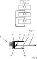
- the Figure 2 represents the equivalent circuit diagram for the laser light source 3.
- the laser light source 3 can accordingly be replaced by a light emitter 3a and an internal resistance R I , 3b arranged in series therewith.
- the laser light source 3 is operated current modulated with a base current I DC and a modulation current I AC .
- Voltage U L is present at the laser light source 3, which drops partly at the internal resistance 3b as partial voltage U RI and at the light emitter 3a as partial voltage U E.
- the Figure 3 illustrates a current / voltage characteristic curve 10 recorded during the calibration of the optical measuring system 1 for determining the internal resistance R I RG of the laser light source 3 at the location of the reference gas.
- the internal resistance R I RG is determined from the relationship of the current-voltage characteristic of the laser light source 3 at the operating point 12 I DC_RG, cal for RG.
- the current-voltage characteristic curve 10 (solid line) is provided with a linear approximation line 11 (dashed line) at the working point 12 for determining the internal resistance R I RG at the location of the reference gas.
- the slope of the approximation line 11 corresponds to the internal resistance R I , 3b at the working point 12 with R I RG .
- a similar procedure is used at the location of the target gas to determine R I ZG .
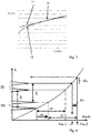
- the Figure 4 exemplifies in a schematic representation the wavelength position of a target gas and that of a reference gas at a specific target temperature, the two positions being at a defined wavelength distance ⁇ DC , which leads to a current distance ⁇ I via the DC tunability curve.
- the absorption lines are solid for the target temperature and dashed for a drift induced by the reduced target temperature.
- the wavelength distance ⁇ DC is set by a constant current distance ⁇ I .
- a shift (drift) of the operating point for example due to the influence of the outside temperature of the sensor on the temperature stabilization or the aging of the laser / electronics, leads to a distance error AI F for the position of the gas peak of the target gas GZ, so that measurement errors result.
- the figure shows schematically the position of the reference and target gas at the time of calibration. The position of the reference gas line is shifted by drift. Due to the non-linear relationship between wavelength and laser current, there is a difference at a fixed current distance ⁇ I , ie an incorrect wavelength with a wavelength distance error ⁇ F , ie a distance error between the calculated and the actual target gas position.
- the error is small (typically ⁇ 20 ⁇ A) and the sensor is still within its specifications for accuracy of concentration. If the error increases, the error rises linearly. In extreme cases, the peak will not even be in the tuning range (in Fig. 4 the target gas is no longer measured, for example). The greater the distance between the reference gas and the target gas, the smaller the allowed drift must be according to this method, otherwise the distance error is> 20 ⁇ A.
- the actual target gas position (associated basic flow) is at position 1 and the target gas position (associated basic flow) calculated using formulas F 1 to F 2 is at position 2. These two target gas positions differ from each other by the distance error ⁇ I F. It should be noted that the DC tunability curve itself is drawn unaffected by a drift. In reality, the DC tunability curve can change even with a long-term drift.
- FIG. 5 is an example of a measurement curve, i.e. a spectrum for methane CH 4 with a lower peak as reference gas and ethane C 2 H 6 as target gas with a higher peak, at a specific target temperature (solid line G 1) and a temperature deviating from the target temperature (dashed line) G 2) shown.
- the deviation of line G 1 from line G 2 is due to a change in the laser temperature and is intended to illustrate the influence of drift on the spacing of the gas peaks.
- the distance error ⁇ I F is shown as an example if a target gas (ethane C 2 H 6 ) is measured at a slightly different laser temperature starting from a reference gas peak (here CH 4 ) with a fixed current distance.
- the temperature reduction results in a shift of the reference gas peak by 0.96 mA. It can be seen that the actual distance between the reference peak and the target gas peak has decreased from 1,669 mA to 1,568 mA. As already mentioned above, this is caused by the non-linear DC tunability of the laser light source. This results in a distance error ⁇ I F of approx. 100 ⁇ A. Applying the proposed method with a fixed temperature change (formula (F 15)) results in a distance error ⁇ I F of only 10 ⁇ A ( Figure 6 ). This means that the target gas signal can be evaluated correctly.
- Figure 6 illustrates the dependence of the distance errors ⁇ I F on the drift values using an example. For various drift values, this shows the distance error ⁇ I F for using a fixed current difference according to formula (F 1) and a fixed temperature difference according to formula (F 15). The values based on the formula F 1 are shown as points P 1 and the values based on the formula F 15 as crosses P 2. It can be seen that with the proposed method, the distance error ⁇ I F of the base current I DC never exceeds 20 ⁇ A, which is sufficiently small to ensure that the measured concentration remains within the specifications.
- Figure 7 illustrates a flowchart for fixing the wavelength distance to a reference wavelength.
- a first method step S1 ie when calibrating the measuring system 1, the The basic DC currents of the peak positions of the reference gas and target gas are determined, and secondly the electrical DC power that drops at the internal resistance of the laser is determined for the two peak positions by determining the internal resistance of the laser at the respective current position.
- the power difference ⁇ P DC, cal of the DC powers is determined and stored in the sensor.
- the electrical DC power that drops at the internal resistance of the laser is first determined for the current peak position of the reference gas by measuring the internal resistance using lock-in technology, then the current electrical DC power at the peak position for the target gas by adding the current DC power for the reference gas peak and the DC power difference between the reference gas and the target gas determined during calibration.
- the DC current for its peak position is then determined, the internal resistance of the target gas from one of the preceding measurements being used according to formula F 11 or F 15, the starting value being the value determined during the calibration. If F 15 is used, the ratio of the current laser temperature to the calibration laser temperature is also used. The laser temperature is saved at the time of calibration.
- the actual measurement scan for the target gas is carried out on the basis of the peak position determined for the target gas, and the gas concentration is determined from this.
- the process steps S2 with S3 are preferably carried out several times in a loop, the basic current I DC_ZG for the target gas position being able to be adapted between the process runs if the current basic current I DC_ZG, act from the ideal basic current I DC_ZG.cal , which is used in the calibration of the optical measuring system has been determined.
Landscapes
- Physics & Mathematics (AREA)
- Spectroscopy & Molecular Physics (AREA)
- General Physics & Mathematics (AREA)
- General Health & Medical Sciences (AREA)
- Health & Medical Sciences (AREA)
- Life Sciences & Earth Sciences (AREA)
- Chemical & Material Sciences (AREA)
- Analytical Chemistry (AREA)
- Biochemistry (AREA)
- Immunology (AREA)
- Pathology (AREA)
- Optics & Photonics (AREA)
- Investigating Or Analysing Materials By Optical Means (AREA)
Priority Applications (1)
| Application Number | Priority Date | Filing Date | Title |
|---|---|---|---|
| CN201910916414.1A CN110987867B (zh) | 2018-10-02 | 2019-09-26 | 用于激光光谱学的光学测量系统中的目标气体的相对定位的方法和系统 |
Applications Claiming Priority (1)
| Application Number | Priority Date | Filing Date | Title |
|---|---|---|---|
| EP18198084 | 2018-10-02 |
Publications (2)
| Publication Number | Publication Date |
|---|---|
| EP3633352A1 true EP3633352A1 (fr) | 2020-04-08 |
| EP3633352B1 EP3633352B1 (fr) | 2020-12-30 |
Family
ID=63722168
Family Applications (1)
| Application Number | Title | Priority Date | Filing Date |
|---|---|---|---|
| EP19160093.1A Active EP3633352B1 (fr) | 2018-10-02 | 2019-02-28 | Procédé et dispositif de référencement relatif d'un gaz cible dans un système de mesure optique pour la spectroscopie laser |
Country Status (2)
| Country | Link |
|---|---|
| EP (1) | EP3633352B1 (fr) |
| CN (1) | CN110987867B (fr) |
Cited By (2)
| Publication number | Priority date | Publication date | Assignee | Title |
|---|---|---|---|---|
| CN115684081A (zh) * | 2023-01-04 | 2023-02-03 | 杭州泽天春来科技有限公司 | 激光气体分析系统 |
| EP4296636A1 (fr) | 2022-06-21 | 2023-12-27 | Carl Zeiss Spectroscopy GmbH | Procédé de pré-étalonnage et de correction d'erreurs de mesure d'un dispositif de mesure spectroscopique et dispositif de mesure |
Families Citing this family (2)
| Publication number | Priority date | Publication date | Assignee | Title |
|---|---|---|---|---|
| CN116879227B (zh) * | 2023-07-07 | 2024-06-11 | 安徽农业大学 | 一种基于激光光谱的快速气体反演方法 |
| CN117928745A (zh) * | 2024-01-22 | 2024-04-26 | 上海频准激光科技有限公司 | 一种目标光束波长偏移量的获取系统 |
Citations (3)
| Publication number | Priority date | Publication date | Assignee | Title |
|---|---|---|---|---|
| EP2307876A1 (fr) | 2008-07-09 | 2011-04-13 | Siemens Aktiengesellschaft | Procédé de détection spectroscopique laser de gaz et détecteur de gaz |
| DE102013202289A1 (de) | 2013-02-13 | 2014-08-28 | Siemens Aktiengesellschaft | Verfahren und Anordnung zur Ansteuerung einer wellenlängendurchstimmbaren Laserdiode in einem Spektrometer |
| WO2018115472A1 (fr) * | 2016-12-23 | 2018-06-28 | Siemens Aktiengesellschaft | Procédé de correction de la longueur d'onde et de la gamme d'accord d'un spectromètre à laser |
Family Cites Families (6)
| Publication number | Priority date | Publication date | Assignee | Title |
|---|---|---|---|---|
| FI101749B (fi) * | 1996-12-30 | 1998-08-14 | Instrumentarium Oy | Kaasukomponentin pitoisuuden tarkka mittaaminen kaasuseoksessa, jossa muut komponentit vaikuttavat pitoisuusmääritykseen |
| EP1850116B1 (fr) * | 2006-04-27 | 2013-09-18 | Axetris AG | Procédé de détection de gaz |
| JP2008268064A (ja) * | 2007-04-23 | 2008-11-06 | Fuji Electric Systems Co Ltd | 多成分対応レーザ式ガス分析計 |
| CN101576489B (zh) * | 2009-05-15 | 2012-04-18 | 重庆同博测控仪器有限公司 | 光干涉检测甲烷或二氧化碳装置及精度自动补偿检测方法 |
| US10775297B2 (en) * | 2016-08-24 | 2020-09-15 | Ecotec Solutions, Inc. | Laser absorption spectroscopy system and method for discrimination of a first and a second gas |
| CN207636485U (zh) * | 2017-11-29 | 2018-07-20 | 珠海任驰光电科技有限公司 | 波长捷变的可调谐半导体激光吸收光谱气体检测装置 |
-
2019
- 2019-02-28 EP EP19160093.1A patent/EP3633352B1/fr active Active
- 2019-09-26 CN CN201910916414.1A patent/CN110987867B/zh active Active
Patent Citations (3)
| Publication number | Priority date | Publication date | Assignee | Title |
|---|---|---|---|---|
| EP2307876A1 (fr) | 2008-07-09 | 2011-04-13 | Siemens Aktiengesellschaft | Procédé de détection spectroscopique laser de gaz et détecteur de gaz |
| DE102013202289A1 (de) | 2013-02-13 | 2014-08-28 | Siemens Aktiengesellschaft | Verfahren und Anordnung zur Ansteuerung einer wellenlängendurchstimmbaren Laserdiode in einem Spektrometer |
| WO2018115472A1 (fr) * | 2016-12-23 | 2018-06-28 | Siemens Aktiengesellschaft | Procédé de correction de la longueur d'onde et de la gamme d'accord d'un spectromètre à laser |
Non-Patent Citations (1)
| Title |
|---|
| CHEN J ET AL: "VCSEL-based calibration-free carbon monoxide sensor at 2.3Â Î 1/4 m with in-line reference cell", APPLIED PHYSICS B ; LASERS AND OPTICS, SPRINGER, BERLIN, DE, vol. 102, no. 2, 28 April 2010 (2010-04-28), pages 381 - 389, XP019880926, ISSN: 1432-0649, DOI: 10.1007/S00340-010-4011-0 * |
Cited By (3)
| Publication number | Priority date | Publication date | Assignee | Title |
|---|---|---|---|---|
| EP4296636A1 (fr) | 2022-06-21 | 2023-12-27 | Carl Zeiss Spectroscopy GmbH | Procédé de pré-étalonnage et de correction d'erreurs de mesure d'un dispositif de mesure spectroscopique et dispositif de mesure |
| CN115684081A (zh) * | 2023-01-04 | 2023-02-03 | 杭州泽天春来科技有限公司 | 激光气体分析系统 |
| CN115684081B (zh) * | 2023-01-04 | 2023-05-05 | 杭州泽天春来科技有限公司 | 激光气体分析系统 |
Also Published As
| Publication number | Publication date |
|---|---|
| CN110987867A (zh) | 2020-04-10 |
| EP3633352B1 (fr) | 2020-12-30 |
| CN110987867B (zh) | 2022-09-30 |
Similar Documents
| Publication | Publication Date | Title |
|---|---|---|
| EP3633352B1 (fr) | Procédé et dispositif de référencement relatif d'un gaz cible dans un système de mesure optique pour la spectroscopie laser | |
| DE102013209751B3 (de) | Laserspektrometer und Verfahren zum Betreiben eines Laserspektrometers | |
| EP2803975B1 (fr) | Procédé destiné à la spectroscopie laser de gaz | |
| DE102012215594B3 (de) | Verfahren zur Laserspektroskopie von Gasen | |
| DE19840345B4 (de) | Verfahren und Vorrichtung zum quantitativen Aufspüren eines vorgegebenen Gases | |
| EP1183520B1 (fr) | Dispositif de capteur de gaz | |
| DE69912758T2 (de) | Verfahren zur wellenlängeneichung einer vorrichtung zur filterung elektromagnetischer strahlung | |
| EP1754395B1 (fr) | Procede de stabilisation de la dependance a la temperature de l'emission lumineuse d'une del | |
| DE69526278T2 (de) | Datenauswertungsverfahren für zur Detektion von Bakterien eingesetzte Fluoreszenzsensoren | |
| DE102013202289B4 (de) | Verfahren und Anordnung zur Ansteuerung einer wellenlängendurchstimmbaren Laserdiode in einem Spektrometer | |
| EP3339839A1 (fr) | Procédé de correction de la longueur d'onde et de la gamme d'accord d'un spectromètre laser | |
| WO2008135416A1 (fr) | Système de détecteur pour analyseur de gaz à infrarouge non dispersif et procédé de détection d'un composant gazeux à mesurer dans un mélange de gaz au moyen d'un tel analyseur de gaz | |
| DE102013213458B4 (de) | Verfahren zur Messung der Konzentration einer Gaskomponente in einem Messgas | |
| DE4122572A1 (de) | Verfahren zum betrieb einer laserdiode | |
| DE112008004262T5 (de) | Sauerstoffkonzentrations-Messvorrichtung | |
| DE102011083750A1 (de) | Verfahren und Anordnung zum Einstellen eines Laserspektrometers | |
| WO2004074774A1 (fr) | Source de lumiere a bande large ultra-stable et procede de stabilisation correspondant | |
| EP2857812B1 (fr) | Procédé de mesure de la concentration d'un composant de gaz dans un gaz de mesure | |
| DE69712053T2 (de) | Gegen umwelteinflüsse unempfindlicher optischer sensor mit verbesserter störsignalunterdrückung | |
| DE102013218771B3 (de) | Verfahren und Gasanalysator zur Messung der Konzentration einer Gaskomponente in einem Messgas | |
| EP2848918A1 (fr) | Analyseur de gaz | |
| EP3816609B1 (fr) | Dispositif et procédé de détection à distance d'un gaz cible | |
| AT500543A1 (de) | Verfahren zur raschen spektroskopischen konzentrations-, temperatur- und druckmessung von gasförmigem wasser | |
| EP3543682B1 (fr) | Procédé de fonctionnement d'un système de mesure optique permettant de mesurer la concentration d'un composant de gaz dans un gaz de mesure | |
| DE102016015424B4 (de) | Vorrichtung zur Bestimmung einer Konzentration eines Gases |
Legal Events
| Date | Code | Title | Description |
|---|---|---|---|
| PUAI | Public reference made under article 153(3) epc to a published international application that has entered the european phase |
Free format text: ORIGINAL CODE: 0009012 |
|
| STAA | Information on the status of an ep patent application or granted ep patent |
Free format text: STATUS: THE APPLICATION HAS BEEN PUBLISHED |
|
| AK | Designated contracting states |
Kind code of ref document: A1 Designated state(s): AL AT BE BG CH CY CZ DE DK EE ES FI FR GB GR HR HU IE IS IT LI LT LU LV MC MK MT NL NO PL PT RO RS SE SI SK SM TR |
|
| AX | Request for extension of the european patent |
Extension state: BA ME |
|
| STAA | Information on the status of an ep patent application or granted ep patent |
Free format text: STATUS: REQUEST FOR EXAMINATION WAS MADE |
|
| REG | Reference to a national code |
Ref country code: DE Ref legal event code: R079 Ref document number: 502019000591 Country of ref document: DE Free format text: PREVIOUS MAIN CLASS: G01N0021390000 Ipc: G01J0003020000 |
|
| 17P | Request for examination filed |
Effective date: 20200427 |
|
| GRAP | Despatch of communication of intention to grant a patent |
Free format text: ORIGINAL CODE: EPIDOSNIGR1 |
|
| STAA | Information on the status of an ep patent application or granted ep patent |
Free format text: STATUS: GRANT OF PATENT IS INTENDED |
|
| RIC1 | Information provided on ipc code assigned before grant |
Ipc: G01J 3/02 20060101AFI20200525BHEP Ipc: G01J 3/10 20060101ALI20200525BHEP Ipc: G01N 21/39 20060101ALI20200525BHEP Ipc: G01J 3/433 20060101ALI20200525BHEP |
|
| INTG | Intention to grant announced |
Effective date: 20200624 |
|
| RBV | Designated contracting states (corrected) |
Designated state(s): AL AT BE BG CH CY CZ DE DK EE ES FI FR GB GR HR HU IE IS IT LI LT LU LV MC MK MT NL NO PL PT RO RS SE SI SK SM TR |
|
| GRAS | Grant fee paid |
Free format text: ORIGINAL CODE: EPIDOSNIGR3 |
|
| GRAJ | Information related to disapproval of communication of intention to grant by the applicant or resumption of examination proceedings by the epo deleted |
Free format text: ORIGINAL CODE: EPIDOSDIGR1 |
|
| GRAL | Information related to payment of fee for publishing/printing deleted |
Free format text: ORIGINAL CODE: EPIDOSDIGR3 |
|
| STAA | Information on the status of an ep patent application or granted ep patent |
Free format text: STATUS: REQUEST FOR EXAMINATION WAS MADE |
|
| STAA | Information on the status of an ep patent application or granted ep patent |
Free format text: STATUS: EXAMINATION IS IN PROGRESS |
|
| GRAP | Despatch of communication of intention to grant a patent |
Free format text: ORIGINAL CODE: EPIDOSNIGR1 |
|
| STAA | Information on the status of an ep patent application or granted ep patent |
Free format text: STATUS: GRANT OF PATENT IS INTENDED |
|
| 17Q | First examination report despatched |
Effective date: 20201020 |
|
| INTC | Intention to grant announced (deleted) | ||
| GRAA | (expected) grant |
Free format text: ORIGINAL CODE: 0009210 |
|
| STAA | Information on the status of an ep patent application or granted ep patent |
Free format text: STATUS: THE PATENT HAS BEEN GRANTED |
|
| INTG | Intention to grant announced |
Effective date: 20201113 |
|
| AK | Designated contracting states |
Kind code of ref document: B1 Designated state(s): AL AT BE BG CH CY CZ DE DK EE ES FI FR GB GR HR HU IE IS IT LI LT LU LV MC MK MT NL NO PL PT RO RS SE SI SK SM TR |
|
| REG | Reference to a national code |
Ref country code: GB Ref legal event code: FG4D Free format text: NOT ENGLISH |
|
| REG | Reference to a national code |
Ref country code: AT Ref legal event code: REF Ref document number: 1350394 Country of ref document: AT Kind code of ref document: T Effective date: 20210115 |
|
| REG | Reference to a national code |
Ref country code: DE Ref legal event code: R096 Ref document number: 502019000591 Country of ref document: DE |
|
| REG | Reference to a national code |
Ref country code: CH Ref legal event code: NV Representative=s name: ABACUS PATENTANWAELTE KLOCKE SPAETH BARTH, CH |
|
| REG | Reference to a national code |
Ref country code: IE Ref legal event code: FG4D Free format text: LANGUAGE OF EP DOCUMENT: GERMAN |
|
| REG | Reference to a national code |
Ref country code: CH Ref legal event code: PLX |
|
| PG25 | Lapsed in a contracting state [announced via postgrant information from national office to epo] |
Ref country code: CH Free format text: LAPSE BECAUSE OF THE APPLICANT RENOUNCES Effective date: 20201230 Ref country code: FI Free format text: LAPSE BECAUSE OF FAILURE TO SUBMIT A TRANSLATION OF THE DESCRIPTION OR TO PAY THE FEE WITHIN THE PRESCRIBED TIME-LIMIT Effective date: 20201230 Ref country code: RS Free format text: LAPSE BECAUSE OF FAILURE TO SUBMIT A TRANSLATION OF THE DESCRIPTION OR TO PAY THE FEE WITHIN THE PRESCRIBED TIME-LIMIT Effective date: 20201230 Ref country code: GR Free format text: LAPSE BECAUSE OF FAILURE TO SUBMIT A TRANSLATION OF THE DESCRIPTION OR TO PAY THE FEE WITHIN THE PRESCRIBED TIME-LIMIT Effective date: 20210331 Ref country code: LI Free format text: LAPSE BECAUSE OF THE APPLICANT RENOUNCES Effective date: 20201230 |
|
| PG25 | Lapsed in a contracting state [announced via postgrant information from national office to epo] |
Ref country code: SE Free format text: LAPSE BECAUSE OF FAILURE TO SUBMIT A TRANSLATION OF THE DESCRIPTION OR TO PAY THE FEE WITHIN THE PRESCRIBED TIME-LIMIT Effective date: 20201230 Ref country code: LV Free format text: LAPSE BECAUSE OF FAILURE TO SUBMIT A TRANSLATION OF THE DESCRIPTION OR TO PAY THE FEE WITHIN THE PRESCRIBED TIME-LIMIT Effective date: 20201230 Ref country code: BG Free format text: LAPSE BECAUSE OF FAILURE TO SUBMIT A TRANSLATION OF THE DESCRIPTION OR TO PAY THE FEE WITHIN THE PRESCRIBED TIME-LIMIT Effective date: 20210330 |
|
| REG | Reference to a national code |
Ref country code: NL Ref legal event code: MP Effective date: 20201230 |
|
| REG | Reference to a national code |
Ref country code: NO Ref legal event code: T2 Effective date: 20201230 |
|
| PG25 | Lapsed in a contracting state [announced via postgrant information from national office to epo] |
Ref country code: HR Free format text: LAPSE BECAUSE OF FAILURE TO SUBMIT A TRANSLATION OF THE DESCRIPTION OR TO PAY THE FEE WITHIN THE PRESCRIBED TIME-LIMIT Effective date: 20201230 |
|
| REG | Reference to a national code |
Ref country code: LT Ref legal event code: MG9D |
|
| PG25 | Lapsed in a contracting state [announced via postgrant information from national office to epo] |
Ref country code: CZ Free format text: LAPSE BECAUSE OF FAILURE TO SUBMIT A TRANSLATION OF THE DESCRIPTION OR TO PAY THE FEE WITHIN THE PRESCRIBED TIME-LIMIT Effective date: 20201230 Ref country code: EE Free format text: LAPSE BECAUSE OF FAILURE TO SUBMIT A TRANSLATION OF THE DESCRIPTION OR TO PAY THE FEE WITHIN THE PRESCRIBED TIME-LIMIT Effective date: 20201230 Ref country code: SK Free format text: LAPSE BECAUSE OF FAILURE TO SUBMIT A TRANSLATION OF THE DESCRIPTION OR TO PAY THE FEE WITHIN THE PRESCRIBED TIME-LIMIT Effective date: 20201230 Ref country code: LT Free format text: LAPSE BECAUSE OF FAILURE TO SUBMIT A TRANSLATION OF THE DESCRIPTION OR TO PAY THE FEE WITHIN THE PRESCRIBED TIME-LIMIT Effective date: 20201230 Ref country code: PT Free format text: LAPSE BECAUSE OF FAILURE TO SUBMIT A TRANSLATION OF THE DESCRIPTION OR TO PAY THE FEE WITHIN THE PRESCRIBED TIME-LIMIT Effective date: 20210430 Ref country code: RO Free format text: LAPSE BECAUSE OF FAILURE TO SUBMIT A TRANSLATION OF THE DESCRIPTION OR TO PAY THE FEE WITHIN THE PRESCRIBED TIME-LIMIT Effective date: 20201230 |
|
| PG25 | Lapsed in a contracting state [announced via postgrant information from national office to epo] |
Ref country code: PL Free format text: LAPSE BECAUSE OF FAILURE TO SUBMIT A TRANSLATION OF THE DESCRIPTION OR TO PAY THE FEE WITHIN THE PRESCRIBED TIME-LIMIT Effective date: 20201230 |
|
| PG25 | Lapsed in a contracting state [announced via postgrant information from national office to epo] |
Ref country code: IS Free format text: LAPSE BECAUSE OF FAILURE TO SUBMIT A TRANSLATION OF THE DESCRIPTION OR TO PAY THE FEE WITHIN THE PRESCRIBED TIME-LIMIT Effective date: 20210430 Ref country code: MC Free format text: LAPSE BECAUSE OF FAILURE TO SUBMIT A TRANSLATION OF THE DESCRIPTION OR TO PAY THE FEE WITHIN THE PRESCRIBED TIME-LIMIT Effective date: 20201230 |
|
| REG | Reference to a national code |
Ref country code: DE Ref legal event code: R097 Ref document number: 502019000591 Country of ref document: DE |
|
| REG | Reference to a national code |
Ref country code: BE Ref legal event code: MM Effective date: 20210228 |
|
| PG25 | Lapsed in a contracting state [announced via postgrant information from national office to epo] |
Ref country code: AL Free format text: LAPSE BECAUSE OF FAILURE TO SUBMIT A TRANSLATION OF THE DESCRIPTION OR TO PAY THE FEE WITHIN THE PRESCRIBED TIME-LIMIT Effective date: 20201230 Ref country code: LU Free format text: LAPSE BECAUSE OF NON-PAYMENT OF DUE FEES Effective date: 20210228 Ref country code: IT Free format text: LAPSE BECAUSE OF FAILURE TO SUBMIT A TRANSLATION OF THE DESCRIPTION OR TO PAY THE FEE WITHIN THE PRESCRIBED TIME-LIMIT Effective date: 20201230 |
|
| PLBE | No opposition filed within time limit |
Free format text: ORIGINAL CODE: 0009261 |
|
| STAA | Information on the status of an ep patent application or granted ep patent |
Free format text: STATUS: NO OPPOSITION FILED WITHIN TIME LIMIT |
|
| PG25 | Lapsed in a contracting state [announced via postgrant information from national office to epo] |
Ref country code: DK Free format text: LAPSE BECAUSE OF FAILURE TO SUBMIT A TRANSLATION OF THE DESCRIPTION OR TO PAY THE FEE WITHIN THE PRESCRIBED TIME-LIMIT Effective date: 20201230 |
|
| 26N | No opposition filed |
Effective date: 20211001 |
|
| PG25 | Lapsed in a contracting state [announced via postgrant information from national office to epo] |
Ref country code: ES Free format text: LAPSE BECAUSE OF FAILURE TO SUBMIT A TRANSLATION OF THE DESCRIPTION OR TO PAY THE FEE WITHIN THE PRESCRIBED TIME-LIMIT Effective date: 20201230 Ref country code: IE Free format text: LAPSE BECAUSE OF NON-PAYMENT OF DUE FEES Effective date: 20210228 |
|
| REG | Reference to a national code |
Ref country code: DE Ref legal event code: R082 Ref document number: 502019000591 Country of ref document: DE Representative=s name: WITTE, WELLER & PARTNER PATENTANWAELTE MBB, DE |
|
| PG25 | Lapsed in a contracting state [announced via postgrant information from national office to epo] |
Ref country code: SI Free format text: LAPSE BECAUSE OF FAILURE TO SUBMIT A TRANSLATION OF THE DESCRIPTION OR TO PAY THE FEE WITHIN THE PRESCRIBED TIME-LIMIT Effective date: 20201230 |
|
| PG25 | Lapsed in a contracting state [announced via postgrant information from national office to epo] |
Ref country code: IS Free format text: LAPSE BECAUSE OF FAILURE TO SUBMIT A TRANSLATION OF THE DESCRIPTION OR TO PAY THE FEE WITHIN THE PRESCRIBED TIME-LIMIT Effective date: 20210430 |
|
| PG25 | Lapsed in a contracting state [announced via postgrant information from national office to epo] |
Ref country code: BE Free format text: LAPSE BECAUSE OF NON-PAYMENT OF DUE FEES Effective date: 20210228 |
|
| P01 | Opt-out of the competence of the unified patent court (upc) registered |
Effective date: 20230502 |
|
| PG25 | Lapsed in a contracting state [announced via postgrant information from national office to epo] |
Ref country code: NL Free format text: LAPSE BECAUSE OF NON-PAYMENT OF DUE FEES Effective date: 20201230 Ref country code: CY Free format text: LAPSE BECAUSE OF FAILURE TO SUBMIT A TRANSLATION OF THE DESCRIPTION OR TO PAY THE FEE WITHIN THE PRESCRIBED TIME-LIMIT Effective date: 20201230 |
|
| PG25 | Lapsed in a contracting state [announced via postgrant information from national office to epo] |
Ref country code: SM Free format text: LAPSE BECAUSE OF FAILURE TO SUBMIT A TRANSLATION OF THE DESCRIPTION OR TO PAY THE FEE WITHIN THE PRESCRIBED TIME-LIMIT Effective date: 20201230 |
|
| PG25 | Lapsed in a contracting state [announced via postgrant information from national office to epo] |
Ref country code: HU Free format text: LAPSE BECAUSE OF FAILURE TO SUBMIT A TRANSLATION OF THE DESCRIPTION OR TO PAY THE FEE WITHIN THE PRESCRIBED TIME-LIMIT; INVALID AB INITIO Effective date: 20190228 |
|
| PG25 | Lapsed in a contracting state [announced via postgrant information from national office to epo] |
Ref country code: MK Free format text: LAPSE BECAUSE OF FAILURE TO SUBMIT A TRANSLATION OF THE DESCRIPTION OR TO PAY THE FEE WITHIN THE PRESCRIBED TIME-LIMIT Effective date: 20201230 |
|
| PG25 | Lapsed in a contracting state [announced via postgrant information from national office to epo] |
Ref country code: MT Free format text: LAPSE BECAUSE OF FAILURE TO SUBMIT A TRANSLATION OF THE DESCRIPTION OR TO PAY THE FEE WITHIN THE PRESCRIBED TIME-LIMIT Effective date: 20201230 |
|
| PGFP | Annual fee paid to national office [announced via postgrant information from national office to epo] |
Ref country code: DE Payment date: 20250326 Year of fee payment: 7 |
|
| REG | Reference to a national code |
Ref country code: AT Ref legal event code: MM01 Ref document number: 1350394 Country of ref document: AT Kind code of ref document: T Effective date: 20240228 |
|
| PGFP | Annual fee paid to national office [announced via postgrant information from national office to epo] |
Ref country code: NO Payment date: 20250221 Year of fee payment: 7 |
|
| PG25 | Lapsed in a contracting state [announced via postgrant information from national office to epo] |
Ref country code: AT Free format text: LAPSE BECAUSE OF NON-PAYMENT OF DUE FEES Effective date: 20240228 |
|
| PGFP | Annual fee paid to national office [announced via postgrant information from national office to epo] |
Ref country code: FR Payment date: 20250224 Year of fee payment: 7 |
|
| PGFP | Annual fee paid to national office [announced via postgrant information from national office to epo] |
Ref country code: GB Payment date: 20250220 Year of fee payment: 7 |
|
| PG25 | Lapsed in a contracting state [announced via postgrant information from national office to epo] |
Ref country code: TR Free format text: LAPSE BECAUSE OF FAILURE TO SUBMIT A TRANSLATION OF THE DESCRIPTION OR TO PAY THE FEE WITHIN THE PRESCRIBED TIME-LIMIT Effective date: 20201230 |