EP3633802B1 - Prise de courant d'appareil, connecteur d'appareil et système de connecteur d'appareil - Google Patents
Prise de courant d'appareil, connecteur d'appareil et système de connecteur d'appareil Download PDFInfo
- Publication number
- EP3633802B1 EP3633802B1 EP19199726.1A EP19199726A EP3633802B1 EP 3633802 B1 EP3633802 B1 EP 3633802B1 EP 19199726 A EP19199726 A EP 19199726A EP 3633802 B1 EP3633802 B1 EP 3633802B1
- Authority
- EP
- European Patent Office
- Prior art keywords
- plug
- socket
- cylindrical shape
- wall
- rotational symmetry
- Prior art date
- Legal status (The legal status is an assumption and is not a legal conclusion. Google has not performed a legal analysis and makes no representation as to the accuracy of the status listed.)
- Active
Links
Images





Classifications
-
- H—ELECTRICITY
- H01—ELECTRIC ELEMENTS
- H01R—ELECTRICALLY-CONDUCTIVE CONNECTIONS; STRUCTURAL ASSOCIATIONS OF A PLURALITY OF MUTUALLY-INSULATED ELECTRICAL CONNECTING ELEMENTS; COUPLING DEVICES; CURRENT COLLECTORS
- H01R13/00—Details of coupling devices of the kinds covered by groups H01R12/70 or H01R24/00 - H01R33/00
- H01R13/73—Means for mounting coupling parts to apparatus or structures, e.g. to a wall
- H01R13/74—Means for mounting coupling parts in openings of a panel
- H01R13/741—Means for mounting coupling parts in openings of a panel using snap fastening means
- H01R13/743—Means for mounting coupling parts in openings of a panel using snap fastening means integral with the housing
-
- H—ELECTRICITY
- H01—ELECTRIC ELEMENTS
- H01R—ELECTRICALLY-CONDUCTIVE CONNECTIONS; STRUCTURAL ASSOCIATIONS OF A PLURALITY OF MUTUALLY-INSULATED ELECTRICAL CONNECTING ELEMENTS; COUPLING DEVICES; CURRENT COLLECTORS
- H01R24/00—Two-part coupling devices, or either of their cooperating parts, characterised by their overall structure
- H01R24/76—Two-part coupling devices, or either of their cooperating parts, characterised by their overall structure with sockets, clips or analogous contacts and secured to apparatus or structure, e.g. to a wall
-
- H—ELECTRICITY
- H01—ELECTRIC ELEMENTS
- H01R—ELECTRICALLY-CONDUCTIVE CONNECTIONS; STRUCTURAL ASSOCIATIONS OF A PLURALITY OF MUTUALLY-INSULATED ELECTRICAL CONNECTING ELEMENTS; COUPLING DEVICES; CURRENT COLLECTORS
- H01R13/00—Details of coupling devices of the kinds covered by groups H01R12/70 or H01R24/00 - H01R33/00
- H01R13/46—Bases; Cases
-
- H—ELECTRICITY
- H01—ELECTRIC ELEMENTS
- H01R—ELECTRICALLY-CONDUCTIVE CONNECTIONS; STRUCTURAL ASSOCIATIONS OF A PLURALITY OF MUTUALLY-INSULATED ELECTRICAL CONNECTING ELEMENTS; COUPLING DEVICES; CURRENT COLLECTORS
- H01R13/00—Details of coupling devices of the kinds covered by groups H01R12/70 or H01R24/00 - H01R33/00
- H01R13/62—Means for facilitating engagement or disengagement of coupling parts or for holding them in engagement
- H01R13/627—Snap or like fastening
-
- H—ELECTRICITY
- H01—ELECTRIC ELEMENTS
- H01R—ELECTRICALLY-CONDUCTIVE CONNECTIONS; STRUCTURAL ASSOCIATIONS OF A PLURALITY OF MUTUALLY-INSULATED ELECTRICAL CONNECTING ELEMENTS; COUPLING DEVICES; CURRENT COLLECTORS
- H01R13/00—Details of coupling devices of the kinds covered by groups H01R12/70 or H01R24/00 - H01R33/00
- H01R13/62—Means for facilitating engagement or disengagement of coupling parts or for holding them in engagement
- H01R13/639—Additional means for holding or locking coupling parts together, after engagement, e.g. separate keylock, retainer strap
-
- H—ELECTRICITY
- H01—ELECTRIC ELEMENTS
- H01R—ELECTRICALLY-CONDUCTIVE CONNECTIONS; STRUCTURAL ASSOCIATIONS OF A PLURALITY OF MUTUALLY-INSULATED ELECTRICAL CONNECTING ELEMENTS; COUPLING DEVICES; CURRENT COLLECTORS
- H01R13/00—Details of coupling devices of the kinds covered by groups H01R12/70 or H01R24/00 - H01R33/00
- H01R13/648—Protective earth or shield arrangements on coupling devices, e.g. anti-static shielding
- H01R13/652—Protective earth or shield arrangements on coupling devices, e.g. anti-static shielding with earth pin, blade or socket
-
- H—ELECTRICITY
- H01—ELECTRIC ELEMENTS
- H01R—ELECTRICALLY-CONDUCTIVE CONNECTIONS; STRUCTURAL ASSOCIATIONS OF A PLURALITY OF MUTUALLY-INSULATED ELECTRICAL CONNECTING ELEMENTS; COUPLING DEVICES; CURRENT COLLECTORS
- H01R13/00—Details of coupling devices of the kinds covered by groups H01R12/70 or H01R24/00 - H01R33/00
- H01R13/648—Protective earth or shield arrangements on coupling devices, e.g. anti-static shielding
- H01R13/655—Protective earth or shield arrangements on coupling devices, e.g. anti-static shielding with earth brace
-
- H—ELECTRICITY
- H01—ELECTRIC ELEMENTS
- H01R—ELECTRICALLY-CONDUCTIVE CONNECTIONS; STRUCTURAL ASSOCIATIONS OF A PLURALITY OF MUTUALLY-INSULATED ELECTRICAL CONNECTING ELEMENTS; COUPLING DEVICES; CURRENT COLLECTORS
- H01R13/00—Details of coupling devices of the kinds covered by groups H01R12/70 or H01R24/00 - H01R33/00
- H01R13/62—Means for facilitating engagement or disengagement of coupling parts or for holding them in engagement
- H01R13/627—Snap or like fastening
- H01R13/6271—Latching means integral with the housing
- H01R13/6272—Latching means integral with the housing comprising a single latching arm
Definitions
- the present invention relates to a device socket, a device connector and a device connector system, consisting of the device socket and the device connector.
- the cable connection box is usually provided in a hole in a wall of the device housing to provide the cable connection.
- the device-external cables are fastened in the cable connection box using clamping screws.
- the device-side cables can be connected to the cable connection socket using blade terminals or soldered connections. This achieves electrical contact between the device-side and device-external cables.
- DE 27 25 796 A1 shows a high-vacuum-tight electrical socket with pin contacts anchored in a housing, one of which is a ground contact and can be connected to a receiving surface of the socket via a metal plate.
- U.S. 3,723,942 A shows an electrical socket with a housing and pin contacts anchored in the housing, one of which is a ground contact and can be connected to a receiving surface of the socket via a metal clip arranged outside and along the housing.
- EP 2 056 412 A2 shows an electrical socket with a housing and pin contacts, which are sealed to the outside by filling waterproof material.
- the surface receiving the socket can be connected to the ground contact of the socket via the socket housing.
- U.S. 2004/077214 A1 , U.S. 7,182,637 B2 and EP 0 597 473 A2 each show a cylindrical electrical socket with electrical contacts anchored in a housing, the socket housing having two opposing straight sections.
- U.S. 2004/077214 A1 and U.S. 7,182,637 B2 each disclose a device socket with the features of the preamble of claim 13.
- the installation space defined by the hole cutout is used as optimally as possible for the connection of the respective cables.
- a first aspect of the present invention relates to a device socket for detachable attachment in a hole cutout of an electrical device.
- the device socket has a socket body with an outer wall which extends at least partially along and otherwise within a cylindrical shape.
- the socket body further includes a connector receiving space which is surrounded by the outer wall and has an insertion opening for inserting a connector in an insertion direction from which the connector receiving space extends.
- the device socket also has at least two electrical contacts, which are arranged within the cylindrical shape and extend in such a way that electrical contact can be made with a plug inserted through the insertion opening.
- One of the contacts is a ground contact.
- the appliance outlet also has a grounding terminal which is electrically coupled to the grounding contact and extends laterally in an outward direction away from the outer wall and substantially orthogonally from an axis of rotational symmetry of the cylindrical shape.
- a simple possibility of connecting device-side and device-external cables by means of a device socket is consequently provided.
- the number of assembly steps and the complexity of the assembly for connecting the respective cable contacts can be significantly reduced.
- the risk of assembly errors and/or assembly inaccuracies can thus also be reduced.
- the special shape of the socket body which extends at least partially within a (virtual) cylindrical shape, means that the functionality required for the device socket is available compactly within a defined installation space can be asked.
- the installation space required for the appliance socket can thus be reduced.
- a component that is essential for safety is defined by the grounding connection with simple means in relation to the box body and is provided with it in a compact manner.
- the device socket according to the invention provides a (twist-proof) connection option for device-side and device-external cables via a hole cutout, which overcomes the above-mentioned disadvantages of the solutions known from the prior art.
- the can body or its outer wall can have two preferably opposite with respect to the axis of rotational symmetry and also preferably parallel and in particular straight first sections within the cylindrical shape, which are separated by at least one second section (or preferably two preferably opposite with respect to the axis of rotational symmetry and second sections extending substantially along the cylindrical shape is (are) connected.
- the first sections and/or the second sections distributed evenly over the circumference of the can body or cylindrical shape.
- the can body may have at least two straight, opposite first sections which are connected by at least one second section extending along the cylindrical shape. This ensures, for example, that the can body can be accommodated in a substantially round hole cutout so that it cannot rotate.
- an anti-twist device can be provided with simple means.
- the installation space required for the appliance socket can be further reduced by providing the straight first sections.
- the assembly of the plug is also made easier, since the device socket is easier to grip on the straight sections.
- the ground connection can extend away from one of the second sections.
- the device socket is provided with an orientation.
- the grounding connection can also serve as a coding means in order to clearly position the device socket in the hole cutout. Furthermore, it can be achieved that the saving in installation space and the simplification of assembly achieved by the provision of the first sections are not adversely affected by the grounding connection. The selected arrangement thus further improves the compactness and ease of assembly of the device socket.
- the grounding connection can extend over a large area, preferably in a plane orthogonal to the axis of rotational symmetry and/or in a plane orthogonal to the direction of insertion.
- the ground connection can thus be provided, for example, parallel to the plane in which the insertion opening is also provided. This is particularly advantageous since this allows electrical contact to be made with the wall of the device housing which has the cutout, and this is achieved with simple structural means. Furthermore, by providing a flat grounding connection, the contact surface with the wall can be enlarged and the electrical coupling of both components can thus be improved.
- the grounding connection can be connected to the grounding contact via a connecting section in order to form a grounding contact element.
- the ground connection and the ground contact can be formed integrally with each other via the connecting portion.
- the contacts and preferably the grounding contact element can be designed as a stamped and bent part for this purpose.
- the design according to the invention makes it possible, for example, for the grounding connection and the grounding contact to be reliably electrically and mechanically coupled to one another. Furthermore, the production and the assembly of the respective elements can be simplified and costs can thus be reduced.
- the connecting section can also preferably extend longitudinally laterally along the outer wall and preferably substantially parallel to the axis of rotational symmetry.
- the connection section can also extend along the second section, which preferably has the ground connection.
- a further contact surface coupled to the grounding contact can be provided by means of the connecting section on the outer wall of the device socket. This makes it possible to provide further connection options with the grounding contact on the outside of the device socket.
- the range of functions of the device socket can thus be expanded without increasing the installation space of the device socket.
- the grounding connection can be provided on a section of the outer wall, preferably on a section of the second section, which is designed as a recess with respect to the cylindrical shape towards the axis of rotational symmetry.
- the recess can extend in a plane parallel to the axis of rotational symmetry.
- the connecting section can extend along the recess and preferably within the cylindrical shape.
- the ground connection can have at least one, preferably two, ground connection openings, the (geometric) center of which is preferably at a distance from the axis of rotational symmetry in the range of 10 mm to 50 mm.
- the two grounding connection openings can be arranged mirror-symmetrically with respect to the grounding connection and/or with respect to a radial of the axis of rotational symmetry.
- the design according to the invention can be achieved, for example, in that the device socket can be used for common hole cutouts. Furthermore, due to the dimensioning, the appliance socket can be made available in a compact manner.
- the ground connection can be secured through the ground connection openings, for example by means of screw connections on the wall of the device housing.
- a section extending along the cylindrical shape, preferably at least one of the second sections, viewed in the direction of the axis of rotational symmetry can extend over an angular range of at least 20° or at least 30° or at least 40° or at least 60° or at least 90° or at least 120° or at least 130°.
- the design according to the invention makes it possible, for example, for the second sections to essentially have a part-circular profile. This makes it possible to design the device socket as compactly as possible and to use it in conjunction with a large number of common industrial hole cutouts.
- the device socket is fitted in the hole cutout by means of a defined area of the socket body.
- a preferred mounting direction can also be indicated by such a structural design of the device socket, so that the mounting is facilitated.
- the support section can be provided at a front end of the can body, viewed in the direction of insertion, and/or in a region of the insertion opening.
- the support section can extend in a plane spanning the insertion opening.
- the support section can extend in a plane orthogonal to the axis of rotational symmetry and/or in a plane orthogonal to the plug-in direction and/or in the plane in which the grounding connection also extends.
- the socket body can have a base section which preferably delimits the plug receiving space on a side opposite the insertion opening.
- the dimensions of the connector receiving space can thus be limited, for example. Furthermore, such an embodiment enables the plug to be positioned in a defined manner in the plug receiving space when a plug is connected to the appliance socket.
- the electrical contacts can extend in the plug-in direction, preferably from the bottom section into the plug-receiving space counter to the plug-in direction.
- the electrical contacts can preferably protrude in the direction of the insertion opening.
- the electrical contacts can preferably extend in or through the socket body, in particular through the base section through its passage opening.
- the electrical contacts can preferably be arranged next to one another, in particular with regard to an elongate direction of the plug receiving space.
- the electrical contacts and/or the ground connection can be detachably connected to the socket body.
- these can be releasably accommodated or releasably held in through-openings which connect the plug-receiving space, preferably via the base section, to a rear side of the socket body.
- the grounding connection could be provided, for example, via the connecting section or merely by means of a further connection to the grounding contact.
- the appliance socket it is also possible, for example, to adapt the appliance socket to different plug types, if necessary.
- the functionality and versatility of the device socket can be improved.
- the electrical contacts can each have a plug contact section for making electrical contact with a plug inserted via the insertion opening and at least one device connection section for connecting electrical contacts on the device.
- the plug contact section can preferably face the plug receiving space or protrude into it.
- the device connection portion may be provided exposed on the back or accessible from the back.
- the device connection section can preferably be designed as a plug-in lug or as a soldering pin.
- the electrical contacts can extend in a plane which preferably extends in or parallel to the axis of rotational symmetry and/or to the direction of insertion.
- the electrical contacts can have an elongated I-shape or Y-shape or an angled L-shape or a T-shape.
- the plug contact section can be provided on an end section and the at least one device connection section can be provided on the opposite end or ends of the respective electrical contact with respect to the plug contact section.
- the device connection sections can preferably extend away from one another in opposite directions in the case of the T-shape and enclose an angle of less than 180° in the case of the Y-shape and preferably extend parallel to one another.
- the respective electrical contacts also have different shapes or combinations of the aforementioned shapes.
- an electrical contact for connecting the device-side cable can be provided in a simple manner on the back of the device socket, which has a small space requirement and facilitates assembly.
- the respective contacts can be produced in a simple manner, for example as stamped and bent parts. Thus, costs can also be reduced.
- the plug-receiving space can have a substantially elongated and/or rectangular and/or asymmetrical, in particular non-rotationally symmetrical, cross-section as seen in the plug-in direction.
- Long sides of the connector receiving space can preferably face the first sections and narrow sides of the connector receiving space can face the second sections.
- the connector receiving space can preferably have at least one convex edge section. Further, the convex edge portion may preferably face the ground terminal with respect to the plug receiving space.
- the connector receiving space With a rectangular profile, it becomes possible to prevent the insertion of the connector with a wrong alignment/orientation with respect to two insertion orientations.
- Such an assembly aid can also be promoted in that the plug receiving space has an asymmetrical cross section or at least one convex edge section in order to clearly define the orientation of the plug when it is plugged in.
- the orientation of the device socket for insertion into the hole cutout can be made recognizable with such a preferred configuration of the plug receiving space, thus facilitating the installation of the device socket.
- the plug receiving space can have at least one coding structure which is designed to correspond to a coding structure partner of a plug inserted into the plug receiving space in such a way as to enable the appliance socket to be connected only to suitable plugs.
- the coding structure can preferably be designed as a projection; the coding structure is particularly preferably provided in the convex edge section.
- the coding structure can preferably extend longitudinally in the plug-in direction or in the direction of the axis of rotational symmetry.
- the device socket can have a coding structure that only allows the insertion of a cable, which is suitable for carrying a specific (minimum) current.
- the coding structure in such a way that cables that are suitable for carrying currents that exceed this (minimum) current intensity are also compatible with the device socket (upward compatibility).
- Poka-Yoke can be used to connect the device socket to a plug in a fail-safe manner. It is thus possible, through the aforesaid preferred configuration of the device socket, to simplify assembly and to provide a cable connection that is less prone to errors.
- the device socket also has at least one latching element.
- This is provided in the area of the outer wall and extends along the cylindrical shape.
- the latching element is pivotable, preferably provided to be movable.
- the latching element also has latching projections projecting laterally away from the axis of rotational symmetry and beyond the cylindrical shape in order to preferably releasably hold the device socket in a part of the hole cutout following the cylindrical shape or in a part following the cross-sectional contour of the outer wall.
- the outer wall can have a pivoting space section which, with regard to the cylindrical shape, forms a free space which preferably extends parallel to the axis of rotational symmetry, in order to optionally accommodate the respective latching element to enable its movement or its pivoting in order to release the mounted Allow device socket or the mounted box body from the hole cutout.
- the appliance socket can have a plurality of latching elements which are preferably distributed evenly over the circumference of the socket body, preferably the outer wall.
- the locking element can also form an independent part of this application.
- the appliance socket can also have a plug retaining lever with a latching projection, which protrudes into the plug receiving space between a latching position, in which it preferably projects radially with respect to the axis of rotational symmetry or with respect to the plug-in direction, viewed in the plug-in direction, and a release position, in which it viewed in the plug-in direction does not protrude into the plug-receiving space, is movably provided.
- the plug holding lever may have a spring portion having a fixing end with which the plug holding lever is fixed to the socket body or the outer wall.
- the spring portion may also have a latching end spaced from or opposite the attachment end, which latching end has the latching projection for pivoting the connector retaining lever over the attachment end.
- the plug holding lever can also achieve a structure that can prevent the plug from being inserted into the appliance socket with a wrong orientation/alignment.
- the provision of the plug retaining lever gives the device socket a type of marking that can be used for the assembly and alignment of the device socket in the cutout. It is thus achieved by the preferred embodiment that a fail-safe connection is provided with reduced assembly effort.
- the connector holding lever can also form an independent part of this application.
- the latching projection can have a starting bevel running obliquely with respect to and preferably counter to the insertion direction, in order to move the connector holding lever from the latched position into the release position only when a connector is inserted into the connector receiving space.
- the plug retaining lever (or in particular the spring section) can extend from the fastening end to the latching end, preferably essentially along the axis of rotational symmetry and towards the insertion opening.
- the plug holding lever can preferably (or at least the spring section) be provided on a plug latching section of the outer wall (preferably the outer wall of one of the first sections), which is designed as a recess with respect to the cylindrical shape towards the axis of rotational symmetry in such a way that the plug holding lever can be pivoted in any position ( but in particular in the locking position and the release position) is arranged within the recess.
- the connector holding lever can have a grip section. This can preferably extend from the latching end and also preferably counter to the insertion direction or preferably protrude from the socket body in such a way that it is possible for an operator to move the connector holding lever between the latching position and the release position.
- the connector holding lever preferably the handle section, can have a stop section which, in relation to a contact plane perpendicular to the axis of rotational symmetry, is inclined in the latching position counter to the plug-in direction such that the stop section extends in the contact plane in the release position, with the contact plane preferably being a corresponds to the plane spanned by the insertion opening.
- the can body and preferably also the support section can be made of plastic.
- the can body and support section are preferably designed/manufactured integrally with one another.
- the can body and/or the support section can consist of different materials, in particular several plastics.
- the can body and/or the support section can preferably be formed by means of an injection molding process, in particular multi-component injection molding (e.g. 2K injection molding) can be produced.
- One of the plastics used can preferably be a sealant material.
- the bearing section can be at least partially (ie the bearing section as a whole or at least a part of the bearing section) designed as a sealing element or made of a preferably elastic sealing material.
- the material of the can body and, if applicable, of the support section can also be used to seal the device housing.
- a second aspect of the present invention relates to a further device socket for detachable attachment in a hole cutout of an electrical device.
- the device socket has a socket body with an outer wall which extends at least partially along and otherwise within a cylindrical shape.
- the socket body further includes a connector receiving space which is surrounded by the outer wall and has an insertion opening for inserting a connector in an insertion direction from which the connector receiving space extends.
- the device socket has at least two electrical contacts, which are arranged within the cylindrical shape and extend in such a way that electrical contact can be made with a plug inserted through the insertion opening.
- the can body or its outer wall has two opposite and preferably parallel straight first sections within the cylindrical shape with respect to an axis of rotational symmetry of the cylindrical shape, which are connected by at least two second sections which lie opposite with respect to the axis of rotational symmetry and extend essentially along the cylindrical shape.
- the device socket has at least one latching element, which is provided in the area of the outer wall and extends along the cylindrical shape, with the latching element being provided in a pivotable manner.
- the latching element has latching projections that protrude laterally away from the axis of rotational symmetry and project beyond the cylindrical shape in order to hold the appliance socket in a part of the hole cutout following the cylindrical shape or in a part following the cross-sectional contour of the outer wall.
- the device socket makes it possible in particular to reduce the number of assembly steps and the complexity of the assembly for the connection of the respective cable contacts.
- the present device socket of the second aspect of the invention has no grounding contact or no grounding connection.
- the anti-twist device socket according to the second aspect of the invention can be achieved by the defined shape of the socket body. This device socket is used in particular for devices that already have such structural insulation (e.g. double-insulated plastic housing) or are supplied with such low power that it is not necessary to provide a grounding contact and grounding connection (for the device housing).
- the device socket according to the second aspect of the invention can, of course, also have any of the aforementioned features according to the first aspect of the invention, with the exception of the grounding connection. For reasons of clarity, the individual features are not listed again below.
- a third aspect of the present invention relates to a device connector system with a device connector which has a contour corresponding to the connector receiving space of one of the aforementioned device sockets for receiving the device connector in the connector receiving space for electrically contacting the contacts of the device socket.
- the appliance plug can have a latching structure which corresponds to the latching projection of the plug holding lever, in order to releasably hold the appliance plug in the plug receiving space in the latching position of the plug holding lever.
- a pull-proof, reliable and compact connection of device-side and device-external cables can be provided by means of the device connector.
- the appliance plug can have a coding structure partner that corresponds to the coding structure of the appliance socket.
- the device connector system also has one of the aforementioned device sockets.
- the device connector system can also have all the features of the device sockets of the first or second aspect of the invention and the features of the aforementioned device connector, which for reasons of clarity are not listed here again in detail together with the resulting advantages.
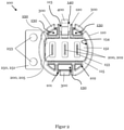
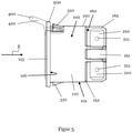
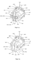
- the Figures 1 to 5 show different views of an embodiment of a device socket 100 according to a first aspect of the invention.
- the Figures 6 to 8 demonstrate a device connector 500 and a device connector system 600 according to the invention.
- the Figures 9A to 9C show a representation of possible (from the prior art) known hole cutouts 700 in a device housing wall GW, which can be used particularly preferably with the device socket 100.
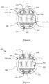
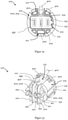
- the Figures 10 to 15 show different views of different embodiments of a device socket 100 according to a second aspect of the invention.
- FIGS. 1 to 5 show different views of an embodiment of a device socket 100 for releasable attachment in the hole cutout 700 of an electrical device according to the first aspect of the invention.
- Device socket 100 shown according to the second aspect can have all the features and developments of the device socket 100 according to the first aspect of the invention accordingly.
- the device socket 100 according to the first aspect can have all the features and developments of the device socket 100 according to the second aspect of the invention. Therefore, a separate presentation and description of the common features of the device sockets 100 according to the invention will be dispensed with below. Rather, special features, deviations and differences between the respective device sockets 100 according to the invention are explicitly pointed out at the relevant points in the description.
- the device socket 100 has a socket body 110 with an outer wall 120 .
- the outer wall 120 extends at least partially along and otherwise within a (virtual) cylindrical shape F. This is evident in particular from FIGS figures 1 , 6 and 7 and 13 to 15.
- the cylindrical shape F is shown as an example.
- the cylindrical shape has an axis of rotational symmetry (not shown) which preferably extends along the longitudinal axis of the cylindrical shape F.
- the can body 110 can have a circular contour with a circle diameter in the range from 10 mm to 100 mm.
- the can body 110 or the cylindrical shape may have a diameter ranging from 18mm to 38mm, 23mm to 33mm, and more preferably from 27mm to 29mm.
- the can body 110 or its outer wall 120 can have two opposite and parallel straight first sections 101 within the cylindrical shape F with respect to the axis of rotational symmetry, as for example in FIGS figures 1 , 2 , 4 and 6 shown.
- the socket body 110 or the outer wall 120 has two opposite and preferably parallel, straight first sections 101 within the cylindrical shape F with respect to an axis of rotational symmetry of the cylindrical shape F, which are defined by at least two second sections 102 which are opposite with respect to the axis of rotational symmetry and extend essentially along the cylindrical shape F are always to be found in the device socket 100 according to the second aspect.
- the first straight sections 101 can preferably be connected by two opposite sections 102 with respect to the axis of rotational symmetry and extending essentially along the cylindrical shape F.
- the first sections 101 and the second sections 102 can be distributed uniformly over the circumference of the can body 110 or the cylindrical shape F.
- At least one of the second sections 102 can extend over an angular range of at least 20° or at least 30° or at least 40° or at least 60° or at least 90° or at least 120° or at least 130°, preferably viewed in the direction of the axis of rotational symmetry.
- the first sections 101 and the second sections 102 are particularly good figures 1 , 2 , 4 and 6 and 10 to 15 can be seen.
- the can body 110 may preferably extend longitudinally along the axis of rotational symmetry, as exemplified in FIGS Figures 1 to 8 and 13-15.
- the can body 110 can preferably have a longitudinal extent in a range from 10 mm to 100 mm.
- the can body 110 can be made of plastic. Furthermore, it is also conceivable that the can body 110 is composed of several plastic components and has, for example, an elastic area for sealing. This can be achieved, for example, by means of a multi-component injection molding process.
- the socket body 110 also has a plug receiving space 150 which is surrounded by the outer wall 120 and has an insertion opening 151 for inserting, for example, a plug 500 described later in an insertion direction E.
- the connector receiving space 150 may extend from the insertion opening 151 .
- this is the figures 1 , 2 and 8th and 10 to 12.
- the direction of insertion E results directly from the insertion direction provided for a plug 500 of the device socket 100 into the device socket 100.
- a plug 500 of the appliance socket 100 is plugged in and unplugged along the axis of rotation of the socket body 110.
- the connector receiving space 150 can have a substantially elongated, rectangular, asymmetric and/or non-rotationally symmetrical cross section. Like the one in particular figures 1 and 2 10 to 12, long sides of the connector receiving space 150 can face the first sections 101. In contrast, the narrow sides of the connector receiving space 150 can face the second sections 102 .
- the connector receiving space 150 can also have at least one convex edge section 154 .
- the connector receiving space 150 can also have at least one coding structure 155 .
- the coding structure 155 can be formed, for example, as a projection from the convex edge section 154 .
- the coding structure 155 can also be designed to correspond to a coding structure partner of a plug 500 inserted into the plug receiving space 150 in such a way that the device socket 100 can only be connected to suitable plugs 500 .
- the coding structure 155 can extend longitudinally in the plug-in direction E (or in the direction of the axis of rotational symmetry). However, it is also conceivable that the coding structure 155 only partially extends in the insertion direction E.
- the appliance socket 100 also has at least two electrical contacts 200, 202, 205.
- the electrical contacts 200, 202, 205 are arranged within the cylindrical shape F and extend in such a way that the plug 500 inserted via the insertion opening 151 can be electrically contacted.
- This can for example figures 1 , 2 and 8th and 10 to 15 can be taken
- one of the contacts 200, 202, 205 of the appliance socket 100 according to the first aspect is a grounding contact 205.
- This can be the, for example figures 1 , 2 and 8th be removed.
- the device socket 100 according to the second aspect of the invention can also have no grounding contact 205, as for example in figure 14 shown.
- the Device socket according to the second aspect of the invention also have a grounding contact 205, such as in the Figures 10 to 13 and 15 is shown.
- grounding contact 205 there are preferably (substantially) no differences between the grounding contact 205 and the at least one electrical contact 202 that is not the grounding contact 205 with regard to their respective electrical conductivity or their shape.
- the electrical contacts 200, 202, 205 can extend in a plane which preferably extends in or parallel to the axis of rotational symmetry and/or direction E of insertion.
- the electrical contacts 200, 202, 205 can extend in the plug-in direction E from a bottom section 152 of the socket body 110, which preferably delimits the plug-receiving space 150 on a side opposite the plug-in opening 151, into the plug-receiving space 150 counter to the plug-in direction E.
- the electrical contacts 200, 202, 205 can protrude from the base section 152 in the direction of the insertion opening 151. This is the particular figures 1 , 2 and 8th to be found, but also in the Figures 10 to 12 implied.
- the electrical contacts 200, 202, 205 can also be accommodated or held in through-openings 153, which connect the plug-accommodating space 150 to a rear side 160 of the socket body 110 via the bottom section 152.
- the electrical contacts 200, 202, 205 can preferably extend through the socket body 110 through the through-openings 153 of the base section 152. This is exemplary in figure 8 shown, but this is also from the Figures 13 to 15 out.
- the electrical contacts 200, 202, 205 can be arranged next to one another, in particular with respect to an elongated direction of the plug receiving space 150, as in FIGS Figures 1 to 8 and 13 to 15 is shown as an example.
- the electrical contacts 200, 202, 205 can each have a plug contact section 220 for making electrical contact with the plug 500 inserted via the plug-in opening 151. Furthermore, the electrical contacts 200, 202, 205 can have at least one device connection section 210 for connecting electrical contacts 200, 202, 205 on the device side. This exemplary embodiment is particularly in figure 8 and partly in figure 1 to recognize as well as in the Figures 10 to 12 implied.
- the plug contact portion 220 can, as in the figures 1 and 8th as well as 10 to 12 shown by way of example, facing the plug receiving space 150 and protruding into it.
- the device connection portion 210 may be exposed on the back 160 or may be accessible from the back 160 .
- the device connection section 210 can be designed, for example, as a plug-in lug or as a soldering pin. However, other configurations of the device connection section 210 are also conceivable. This is exemplary in the figures 1 , 3 to 8 as 13 to 15 shown.
- the plug contact section 220 and the at least one device connection section 210 can be provided at opposite ends of the electrical contact 200, 202, 205.
- the electrical contacts 200, 202, 205 can thus have, for example, an elongated I-shape, Y-shape, an angled L-shape or a T-shape or any other desired shape.
- FIG 15 An embodiment is shown in which the electrical contacts 200, 202, 205 have a Y-shape.
- the exemplary embodiment illustrated therein is not limited to the device socket 100 according to the second aspect, but can also be found for the device socket 100 according to the first aspect.
- the T-shape allows the device connection portions 210 to extend oppositely from each other.
- the respective device connection sections 210 can also have through-openings 211 in order to facilitate attachment to the device-side cables. This is exemplary in the figures 1 , 5 , 7 and 8th and 13 to 15 can be seen.
- the aforementioned Y-shape of the electrical contacts 200, 202, 205 requires a longer extension to the rear (cf. e.g. figure 15 ) than the T-shape requires (cf. e.g. Figures 3 , 6 , 13 and 14 ), so that the latter configuration enables an overall more compact design of the device socket 100.
- the electrical contacts 200, 202, 205 may be detachably connected to the box body 110.
- the electrical contacts 200, 202, 205 can have fastening cutouts 260, for example, into which fastening springs 161 on the rear side 160 engage.
- the mounting springs 161 are preferably part of, and more preferably integral with, the separating portions 162 . This is exemplary in the figures 4 , 5 , 6 and 8th and 13-15.
- the electrical contacts 200, 202, 205 can have a stop section 231, with which the respective electrical contact 200, 202, 205 bears against the bottom section 152. For example, this is in figure 8 shown.
- the device socket 100 can also have a support section 116 for resting on an edge region of the hole cutout 700 receiving the socket body 110 , with at least the rear side of the socket body 110 being received through the hole cutout 700 .
- the support section 116 can be formed, for example, by a ring-like projection 115 running around the circumference of the outer wall 120 on the outside of the can body 110 (away from the outside), as exemplified in FIGS Figures 1 to 8 and 10-15.
- the support section 116 can also be provided on a front end of the can body 110 viewed in the insertion direction E. Alternatively or additionally, the support section 116 can extend in a plane spanning the insertion opening 151 .
- the device socket 100 can also have a plug retaining lever 400, which has a latching projection 430, which protrudes between a latching position, in which it preferably projects radially with respect to the axis of rotational symmetry or with respect to the plug-in direction E, viewed in the plug-in direction E, and into the plug-receiving space 150, and a release position, in which it does not protrude into the connector receiving space 150, seen in the direction of insertion E, is movably provided.
- the Figures 1 to 8 and FIGS. 10 through 15 show the connector retaining lever 400 in the latched position.
- the plug holding lever 400 may further include a spring portion 420 having a fixing end with which the plug holding lever 400 is fixed to the socket body 110 or the outer wall 120 .
- the spring portion 420 may further include a latching end spaced from or opposite the attachment end, which includes the latching projection 430 to pivot the connector retaining lever 400 over the attachment end.
- the connector holding lever 400 (and in particular the spring section 420) can extend from the fastening end to the latching end essentially along the axis of rotational symmetry and towards the insertion opening 151. This can in particular figure 8 as well as the Figures 13 to 15 be removed.
- the connector holding lever 400 may be provided at a connector latching portion of the outer wall 120 .
- the connector holding lever 400 can be provided on one of the first sections 101, which can be designed as a recess 113 with respect to the cylindrical shape F towards the axis of rotational symmetry.
- the recess 113 can be designed in such a way that the plug holding lever 400 is arranged within the recess 113 in every pivoting position, in particular in the locking position and the release position. It is also possible that a further free space 140 is formed by the recess 113, as for example in figure 2 and Figures 13-15.
- the plug retaining lever 400 may further include a handle portion 410, which may extend from the latching end and counter to the insertion direction E, while protruding from the socket body 110, to allow an operator to move the plug retaining lever 400 between the latched position and the release position .
- the handle portion 410 is in particular the Figures 3 and 5 and 13 to 15 shown in an advantageous manner.
- the handle section 410 can have a stop section 440, which is inclined at an angle ⁇ counter to the insertion direction E with respect to a contact plane perpendicular to the axis of rotational symmetry in the latching position such that the stop section 440 extends in the contact plane in the release position.
- the contact plane can correspond to a plane spanned by the insertion opening 151 .
- the angle ⁇ can extend over an angular range of at least 5°, 10°, 20° or 50°.
- the device socket 100 according to the first aspect of the invention additionally has a ground connection 251 which is electrically coupled to the ground contact 205 and extends laterally in one direction from the outer wall 120 and essentially orthogonally extends outwardly from an axis of rotational symmetry of the cylindrical shape F.
- the device socket 100 according to the second aspect can be primarily intended for applications in which such a grounding of the device housing wall GW and/or the device is not necessary.
- the device socket 100 can also be used for applications that require the device housing wall GW to be grounded.
- the ground connection 251 can extend away from one of the second sections 102 .
- the ground connection 251 can extend over a surface area in a plane orthogonal to the axis of rotational symmetry. This is exemplified in the figures 1 , 2 , 4 shown.
- the grounding terminal 251 may be connected to the grounding contact 205 via a connection portion 252 to form a grounding contact element 250 .
- the connection section 252 can be connected directly to the grounding contact 205, in particular the Figures 3 and 4 can be seen.
- the grounding terminal 251 and the grounding contact 205 can be formed integrally with each other via the connecting portion 252, such as that shown in FIG Figures 3 and 4 can be seen.
- Both the contacts 200, 202, 205 and the grounding contact element 250 can preferably be designed as a stamped and bent part.
- the electrical contacts 200, 202, 205 can be made of copper or another (noble) metal, for example.
- the ground terminal 251 and/or the connecting portion 252 can also be made of a metallic material.
- the ground connection 251 can also have two ground connection openings 253, the geometric center of which can have a distance from the axis of rotational symmetry in the range of 10 mm to 50 mm.
- the two ground connection openings 253 can be arranged mirror-symmetrically with respect to the ground connection 251 and/or with respect to a radial of the axis of rotational symmetry. This is shown in particular by Figures 1 to 4 .
- the connecting portion 252 may extend longitudinally laterally along the outer wall 120 and substantially parallel to the axis of rotational symmetry.
- the connection section 252 can extend along the second section 102 having the ground connection 251 . For example, this is in figure 3 shown.
- the ground connection 251 can also be provided on a section of the outer wall 120 which is designed as the recess 112 with respect to the cylindrical shape F towards the axis of rotational symmetry.
- the connecting section 252 can preferably extend along the recess 112 and further preferably within the cylindrical shape F. For example, this is in figure 3 shown. the Figures 13 to 15 also show the recess 112 as an example.
- the ground terminal 251 may also face the at least one convex edge portion 154 with respect to the connector receiving space 150 .
- the ground connection 251 can also extend in a plane in which the support section 116 also extends and which can preferably be orthogonal to the plug-in direction E or orthogonal to the axis of rotational symmetry. This can in particular figure 1 be removed.
- the Figures 6 to 8 also show a device connector system 600.
- the device connector system 600 has the device socket 100 on.
- both the device socket 100 according to the first aspect and/or according to the second aspect of the invention can be used in the device connector system 600 .
- the device connector system 600 also has a device connector 500 which corresponds to the device socket 100 .
- the appliance plug 500 is set up to electrically contact the contacts 200 , 202 , 205 of the appliance socket 100 by receiving the appliance plug 500 in the plug receiving space 150 .
- the appliance plug 500 can have a contour corresponding to the plug receiving space 150 of the appliance socket 100 for receiving the appliance plug 500 in the plug receiving space 150 .
- the device connector 500 can have a cable 560 which is connected to the connector head 530 of the device connector 500 .
- a plug contact section 515 can be provided on the plug head 530 with which the plug head 530 rests on the device socket 100 .
- the plug head 530 can also have a plug-in section 550 in which the electrical contacts 520 of the appliance plug 500 can be provided. This is particularly in figure 8 shown.
- the appliance plug 500 can have a latching structure 531 corresponding to the latching projection 430 of the plug holding lever 400 in order to hold the appliance plug 500 in the latching position of the plug holding lever 400 in the plug receiving space 150 in a detachable manner.
- Figures 9A to 9C show different hole cutouts 700 from a device housing wall GW, which can be used particularly preferably with the device sockets 100 presented according to the first and the second aspect of the invention and with the device connector system 600 presented.
- the device sockets 100 are particularly preferably designed in such a way that their contour corresponds to the contour of the hole cutout 700 or at least partially follows the contour of the hole cutout 700 . All of the following dimensions also include the deviations caused by manufacturing tolerances.
- the hole cutouts 700 each have a circular contour with two parallel straight sections lying opposite one another with respect to the center of the circle.
- the circular contour of the respective hole section 700 can extend with a circular diameter of at least 10 mm, 15 mm, 20 mm or 25 mm.
- the respective circular contours with a circle diameter of extend a maximum of 100mm, 90mm, 80mm, 70mm, 60mm, 50mm, 40mm or 30mm.
- the circular contour particularly preferably has a circle diameter of 28.5 mm.
- the straight sections 701 may be spaced from each other in a range of at least 10mm, 15mm, 20mm or 25mm (horizontally).
- the straight sections 701 are particularly preferably spaced apart from one another by 26.0 mm.
- the additional punched-out portions 705 can be formed by two circular sections spaced apart from one another.
- the two sectors of a circle are preferably at a distance in a range of at least 10 mm, 15 mm, 20 mm or 25 mm.
- the two sectors of a circle are particularly preferably spaced apart from one another by 14.0 mm.
- the two sectors of a circle can each have a vertical spacing from the center point of the circular contour.
- the vertical spacing can have a range of at least 10 mm, 15 mm, 20 mm or 25 mm.
- the two circular sections are vertically spaced 18.0 mm from the center point of the circular contour.
Landscapes
- Connector Housings Or Holding Contact Members (AREA)
- Details Of Connecting Devices For Male And Female Coupling (AREA)
Claims (15)
- Prise de courant d'appareil (100) pour une fixation amovible dans une découpe en forme de trou (700) d'un appareil électrique, présentant• un corps de prise (110) avec une paroi extérieure (120) qui s'étend au moins partiellement le long d'une forme cylindrique (F) pour finir à l'intérieur de celle-ci, et un espace d'accueil de fiche (150) qui est entouré par la paroi extérieure (120) et un orifice d'insertion (151) destiné à l'introduction d'une fiche (500) dans une direction d'insertion (E) et à partir duquel s'étend l'espace d'accueil de fiche (150) ;• au moins deux contacts électriques (200, 202, 205) qui sont agencés à l'intérieur de la forme cylindrique (F) et s'étendent de manière à venir en contact électrique avec une fiche (500) introduite dans l'orifice d'insertion (151), dans laquelle l'un des contacts (200, 202, 205) est un contact de mise à la terre (205) ; et• une connexion de mise à la terre (251) qui est couplée électriquement au contact de mise à la terre (205) et s'étend latéralement dans une direction s'éloignant de la paroi extérieure (120) et de manière essentiellement orthogonale par rapport à un axe de symétrie de rotation de la forme cylindrique (F),caractérisée en ce quela prise de courant d'appareil (100) présente en outre au moins un élément d'encliquetage (300) qui est prévu dans la région de la paroi extérieure (120) et s'étend le long de la forme cylindrique (F), dans laquelle l'élément d'encliquetage (300) est pivotant, etdans laquelle l'élément d'encliquetage (300) présente des saillies d'encliquetage (310) dépassant de la forme cylindrique (F) latéralement vers l'extérieur en s'éloignant de l'axe de symétrie de rotation afin de maintenir la prise de courant d'appareil (100) dans une partie de la découpe en forme de trou (700) qui suit la forme cylindrique (F) ou qui suit le contour de section transversale de la paroi extérieure (120).
- Prise de courant d'appareil (100) selon la revendication 1, dans laquelle le corps de prise (110) ou sa paroi extérieure (120) présente à l'intérieur de la forme cylindrique (F) deux premières sections (101) de manière préférée opposées par rapport à l'axe de symétrie de rotation et de manière plus préférée parallèles et de manière particulièrement préférée rectilignes, qui sont reliées grâce à au moins une et de manière préférée deux deuxièmes sections (102) de manière plus préférée opposées par rapport à l'axe de symétrie de rotation et s'étendant essentiellement le long de la forme cylindrique (F), dans laquelle les premières sections (101) et/ou les deuxièmes sections (102) sont agencées de manière uniformément répartie sur le périmètre du corps de prise (110) ou de la forme cylindrique (F), dans laquelle la connexion de mise à la terre (251) s'étend de manière préférée en s'éloignant de l'une des deuxièmes sections (102).
- Prise de courant d'appareil (100) selon l'une quelconque des revendications précédentes,dans laquelle la connexion de mise à la terre (251) s'étend à plat, de manière préférée dans un plan de manière orthogonale par rapport à l'axe de symétrie de rotation et/ou dans un plan de manière orthogonale par rapport à la direction d'insertion (E), et/oudans laquelle la connexion de mise à la terre (251) est raccordée au contact de mise à la terre (205) par l'intermédiaire d'une section de raccordement (252) afin de former un élément de contact de mise à la terre (250), dans laquelle la section de raccordement (252) s'étend de manière préférée latéralement le long de la paroi extérieure (120) et de manière préférée de manière essentiellement parallèle longitudinalement par rapport à l'axe de symétrie de rotation, et/ou dans laquelle la section de raccordement (252) s'étend de manière préférée le long de la deuxième section (102) présentant la connexion de mise à la terre (251), et/oudans laquelle la connexion de mise à la terre (251) est fournie sur une section de la paroi extérieure (120), de manière préférée de la deuxième section (102), qui est réalisée sous forme de décrochement (112) par rapport à la forme cylindrique (F) vers l'axe de rotation de symétrie, dans laquelle le décrochement (112) s'étend de manière préférée dans un plan de manière parallèle à l'axe de symétrie de rotation, dans laquelle la section de raccordement (252) s'étend de manière préférée le long du décrochement (112) et de manière plus préférée à l'intérieur de la forme cylindrique (F).
- Prise de courant d'appareil (100) selon l'une quelconque des revendications précédentes, dans laquelle la connexion de mise à la terre (251) présente au moins un, de manière préférée deux orifices de connexion de mise à la terre (253) dont le centre (géométrique) présente de manière préférée une distance par rapport à l'axe de symétrie de rotation située dans la plage comprise entre 10 mm et 50 mm,
dans laquelle les deux orifices de connexion de mise à la terre (253) sont de manière préférée agencés symétriquement par rapport à la connexion de mise à la terre (251) et/ou par rapport à une ligne radiale de l'axe de symétrie de rotation. - Prise de courant d'appareil (100) selon l'une quelconque des revendications précédentes,dans laquelle une section s'étendant le long de la forme cylindrique (F), de manière préférée au moins l'une des deuxièmes sections (102), vue dans la direction de l'axe de symétrie de rotation, s'étend sur une plage angulaire d'au moins 20° ou d'au moins 30° ou d'au moins 40° ou d'au moins 60° ou d'au moins 90° ou d'au moins 120° ou d'au moins 130°, et/oudans laquelle le corps de prise (110) s'étend longitudinalement le long de l'axe de symétrie de rotation, de manière préférée avec une extension longitudinale située dans une plage comprise entre 10 mm et 100 mm, et/oudans laquelle le corps de prise (110) présente, dans une région au sein de laquelle la paroi extérieure (120) s'étend le long de la forme cylindrique (F), de manière préférée vue dans la direction d'insertion (E), un contour circulaire avec un diamètre de cercle situé dans une plage comprise entre 10 mm et 100 mm, et/ou dans laquelle la forme cylindrique (F) présente un diamètre situé dans la plage comprise entre 10 mm et 100 mm.
- Prise de courant d'appareil (100) selon l'une quelconque des revendications précédentes, présentant en outre une section d'appui (116) pour un appui au niveau d'une région de bord de la découpe en forme de trou (700) accueillant la prise de courant d'appareil (100), de manière préférée le corps de prise (110), au moins partiellement, de manière préférée au moins le dos du corps de prise (110), dans laquelle la section d'appui (116) est de manière préférée formée par une saillie (115), de manière préférée annulaire et s'étendant au moins partiellement de manière périphérique à l'extérieur au niveau de la paroi extérieure (120), du corps de prise (110),dans laquelle la section d'appui (116) est fournie de manière préférée au niveau d'une extrémité avant, vue dans la direction d'insertion (E), du corps de prise (110) et/ou dans une région de l'orifice insertion (151), et/ou s'étend dans un plan comprenant l'orifice d'insertion (151), et/oudans laquelle la section d'appui (116) s'étend de manière préférée dans un plan de manière orthogonale par rapport à l'axe de symétrie de rotation et/ou dans un plan de manière orthogonale par rapport à la direction d'insertion (E) et/ou dans le plan dans lequel s'étend également la connexion de mise à la terre (251).
- Prise de courant d'appareil (100) selon l'une quelconque des revendications précédentes, dans laquelle le corps de prise (110) présente une section de fond (152) qui délimite l'espace d'accueil de fiche (150) de manière préférée au niveau d'un côté opposé à l'orifice d'insertion (151).
- Prise de courant d'appareil (100) selon l'une quelconque des revendications précédentes, dans laquelle les contacts électriques (200, 202, 205) présentent respectivement une section de contact de fiche (220) pour l'établissement d'un contact électrique avec une fiche (500) introduite dans l'orifice d'insertion (151) et au moins une section de connexion d'appareil (210) pour connecter des contacts électriques (200, 202, 205) situés côté appareil,dans laquelle la section de contact de fiche (220) fait de manière préférée face à l'espace d'accueil de fiche (150) ou fait saillie dans celui-ci,dans laquelle la section de connexion d'appareil (210) est de manière préférée fournie de manière à être exposée sur le côté arrière (160) ou est accessible depuis le côté arrière (160), et/ou dans laquelle la section de connexion d'appareil (210) est réalisée sous forme de languette insérable ou de broche à souder.
- Prise de courant d'appareil (100) selon l'une quelconque des revendications précédentes, dans laquelle l'espace d'accueil de fiche (150) présente, vu dans la direction d'insertion (E), une section transversale essentiellement oblongue et/ou rectangulaire et/ou asymétrique, en particulier non symétrique en rotation, dans laquelle de manière préférée les côtés longs de l'espace d'accueil de fiche (150) font face aux premières sections (101) et les côtés courts de l'espace d'accueil de fiche (150) font face aux deuxièmes sections (102),dans laquelle les contacts électriques (200, 202, 205) sont agencés de manière préférée les uns à côté des autres, en particulier par rapport à une direction longitudinale de l'espace d'accueil de fiche (150),dans laquelle l'espace d'accueil de fiche (150) présente de manière préférée au moins une section de bord convexe (154) qui se trouve en outre de manière préférée à l'opposé de la connexion de mise à la terre (251) par rapport à l'espace d'accueil de fiche (150).
- Prise de courant d'appareil (100) selon l'une quelconque des revendications précédentes, dans laquelle l'espace d'accueil de fiche (150) présente au moins une structure de codage (155) conçue pour correspondre à un partenaire de structure de codage d'une fiche (500) introduite dans l'espace d'accueil de fiche (150) de manière à ne permettre le raccordement de la prise de courant d'appareil (100) qu'avec des fiches appropriées,
dans laquelle la structure de codage (155) est de manière préférée réalisée sous forme de saillie, de manière particulièrement préférée dans la section de bord convexe (154), et/ou• la structure de codage (155) s'étend longitudinalement dans la direction d'insertion (E) ou dans la direction de l'axe de symétrie de rotation. - Prise de courant d'appareil (100) selon l'une quelconque des revendications précédentes, dans laquelle la paroi extérieure (120) dans la région de l'élément d'encliquetage (300) présente une section d'espace de pivotement (130) qui forme par rapport à la forme cylindrique (F) un espace libre (130), de manière préférée un espace libre (130) s'étendant parallèlement à l'axe de symétrie de rotation, afin d'accueillir de manière sélective l'élément d'encliquetage respectif (300) et permettre son mouvement ou son pivotement afin de retirer de la découpe en forme de trou (700) la prise de courant d'appareil (100) lorsqu'elle est en place ou le corps de prise (110) lorsqu'il est en place, et/ou
dans laquelle la prise courant d'appareil (100) présente plusieurs éléments d'encliquetage (300) qui sont agencés de manière préférée de manière uniformément répartie sur le périmètre du corps de prise (110), de manière préférée de la paroi extérieure (120). - Prise de courant d'appareil (100) selon l'une quelconque des revendications précédentes, dans laquelle la prise de courant d'appareil (100) présente en outre un levier de maintien de fiche (400) qui présente une saillie d'encliquetage (430) qui est fournie mobile entre une position d'encliquetage dans laquelle elle fait saillie dans l'espace d'accueil de fiche (150), vue dans la direction d'insertion (E), de manière préférée radialement par rapport à l'axe de symétrie de rotation ou à la direction d'insertion (E), et une position de libération dans laquelle elle ne fait pas saillie dans l'espace d'accueil de fiche (150), vue dans la direction d'insertion (E),dans laquelle la saillie d'encliquetage (430) présente de manière préférée un chanfrein (431) s'étendant de manière oblique par rapport à, et de manière préférée à l'encontre de, la direction d'insertion (E) afin de déplacer le levier de maintien de fiche (400) de la position d'encliquetage vers la position de libération uniquement lors de l'insertion d'une fiche (500) dans l'espace d'accueil de fiche (150), et/oudans laquelle le levier de maintien de fiche (400) présente de manière préférée une section à ressort (420) avec une extrémité de fixation avec laquelle le levier de maintien de fiche (400) est fixé au corps de prise (110) ou à la paroi extérieure (120), et une extrémité d'encliquetage espacée par rapport à l'extrémité de fixation ou située à l'opposé de celle-ci et qui présente la saillie d'encliquetage (430) afin de faire pivoter le levier de maintien de fiche (400) sur l'extrémité de fixation,dans laquelle le levier de maintien de fiche (400), en particulier la section à ressort (420), s'étend de manière préférée de l'extrémité de fixation vers l'extrémité d'encliquetage de manière préférée essentiellement le long de l'axe de symétrie de rotation et vers l'orifice d'insertion (151), et/oudans laquelle le levier de maintien de fiche (400), de manière préférée au moins la section à ressort (420), est fourni de manière préférée au niveau d'une section d'encliquetage de fiche de la paroi extérieure (120), de manière préférée de l'une des premières sections (101), réalisée sous forme de décrochement (113) par rapport à la forme cylindrique (F) vers l'axe de symétrie de rotation, de telle manière que le levier de maintien de fiche (400) est agencé à l'intérieur du décrochement (113) dans chaque position de pivotement, en particulier dans la position d'encliquetage et la position de libération, et/oudans laquelle de manière préférée le levier de maintien de fiche (400) présente une section de préhension (410) qui s'étend, de manière préférée dépasse du corps de prise (110), de manière préférée à partir de l'extrémité d'encliquetage et en outre de manière préférée à l'encontre de la direction d'insertion (E) de manière à permettre (à un opérateur) de déplacer le levier de maintien de fiche (400) entre la position d'encliquetage et la position de libération, et/oudans laquelle de manière préférée le levier de maintien de fiche (400), de manière préférée la section de préhension (410), présente une section de butée (440) qui est inclinée à l'encontre de la direction d'insertion (E), par rapport à un plan de contact perpendiculaire à l'axe de symétrie de rotation dans le position d'encliquetage, de sorte que la section de butée (440) en position de libération s'étend dans le plan de contact, dans laquelle le plan de contact correspond de manière préférée à un plan traversé par l'orifice d'insertion (151).
- Prise de courant d'appareil (100) pour une fixation amovible dans une découpe en forme de trou (700) d'un appareil électrique, présentant• un corps de prise (110) avec une paroi extérieure (120) qui s'étend au moins partiellement le long d'une forme cylindrique (F) pour finir à l'intérieur de celle-ci, et un espace d'accueil de fiche (150) qui est entouré par la paroi extérieure (120) et un orifice d'insertion (151) destiné à l'introduction d'une fiche (500) dans une direction d'insertion (E) et à partir duquel s'étend l'espace d'accueil de fiche (150) ; et• au moins deux contacts électriques (200, 202, 205) qui sont agencés à l'intérieur de la forme cylindrique (F) et s'étendent de manière à établir un contact électrique avec une fiche (500) introduite dans l'orifice d'insertion (151) ;dans laquelle le corps de prise (110) ou sa paroi extérieure (120) présente à l'intérieur de la forme cylindrique (F) deux premières sections rectilignes (101), opposées par rapport à un axe de symétrie de rotation de la forme cylindrique (F) et de manière préférée parallèles, qui sont reliées grâce à au moins deux deuxièmes sections (102) opposées par rapport à l'axe de symétrie de rotation et s'étendant essentiellement le long de la forme cylindrique (F), dans laquelle la prise de courant d'appareil (100) présente en outre au moins un élément d'encliquetage (300) qui est fourni dans la région de la paroi extérieure (120), dans laquelle l'élément d'encliquetage (300) est fourni pivotant,
caractérisée en ce que
l'élément d'encliquetage (300) s'étend le long de la forme cylindrique (F), dans laquelle l'élément d'encliquetage (300) présente des saillies d'encliquetage (310) dépassant de la forme cylindrique (F) latéralement vers l'extérieur en s'éloignant de l'axe de symétrie de rotation, afin de maintenir la prise de courant d'appareil (100) dans la forme cylindrique (F) ou dans une partie de la découpe en forme de trou (700) qui suit le contour de coupe transversale de la paroi extérieure (120). - Système de prise d'appareil, présentant• une prise de courant d'appareil (100) selon l'une quelconque des revendications 1 à 13, et• une fiche d'appareil (500) pour l'établissement d'un contact électrique avec les contacts (200, 202, 205) de la prise de courant d'appareil (100) grâce à l'accueil de la fiche d'appareil (500) dans l'espace d'accueil de fiche (150),dans laquelle la fiche d'appareil (500) présente un contour correspondant à l'espace d'accueil de fiche (150) de la prise de courant d'appareil (100) et destiné à accueillir la fiche d'appareil (500) dans l'espace d'accueil de fiche (150) afin d'établir un contact électrique avec les contacts (200, 202, 205) de la prise de courant d'appareil (100).
- Système de prise d'appareil selon la revendication 14, dans lequel la prise de courant d'appareil (100) est réalisée selon la revendication 12 et la fiche d'appareil (500) présente une structure d'encliquetage (531) correspondant à la saillie d'encliquetage (430) du levier de maintien de fiche (400) afin, dans la position d'encliquetage du levier de maintien de fiche (400), de maintenir amovible la fiche d'appareil (500) dans l'espace d'accueil de fiche (150),
dans lequel la prise de courant d'appareil (100) est en outre réalisée de manière préférée selon la revendication 10 et la fiche d'appareil (500) présente un partenaire de structure de codage correspondant à la structure de codage (155).
Priority Applications (1)
| Application Number | Priority Date | Filing Date | Title |
|---|---|---|---|
| SI201930220T SI3633802T1 (sl) | 2018-10-01 | 2019-09-26 | Vtičnica naprave, vtič naprave in sistem vtiča naprave |
Applications Claiming Priority (1)
| Application Number | Priority Date | Filing Date | Title |
|---|---|---|---|
| DE202018105641.7U DE202018105641U1 (de) | 2018-10-01 | 2018-10-01 | Gerätesteckdose, Gerätestecker und Gerätesteckersystem |
Publications (2)
| Publication Number | Publication Date |
|---|---|
| EP3633802A1 EP3633802A1 (fr) | 2020-04-08 |
| EP3633802B1 true EP3633802B1 (fr) | 2022-03-02 |
Family
ID=68069634
Family Applications (1)
| Application Number | Title | Priority Date | Filing Date |
|---|---|---|---|
| EP19199726.1A Active EP3633802B1 (fr) | 2018-10-01 | 2019-09-26 | Prise de courant d'appareil, connecteur d'appareil et système de connecteur d'appareil |
Country Status (5)
| Country | Link |
|---|---|
| EP (1) | EP3633802B1 (fr) |
| CN (1) | CN110970777A (fr) |
| DE (1) | DE202018105641U1 (fr) |
| PL (1) | PL3633802T3 (fr) |
| SI (1) | SI3633802T1 (fr) |
Families Citing this family (5)
| Publication number | Priority date | Publication date | Assignee | Title |
|---|---|---|---|---|
| JP7453067B2 (ja) | 2020-06-05 | 2024-03-19 | 矢崎総業株式会社 | コネクタセット |
| CN113328316B (zh) * | 2021-04-25 | 2022-06-03 | 佛山照明智达电工科技有限公司 | 一种插座点焊一体机 |
| DE102021127030B3 (de) * | 2021-10-19 | 2022-12-22 | Md Elektronik Gmbh | Steckverbinder |
| US12500375B2 (en) * | 2022-05-19 | 2025-12-16 | Japan Aviation Electronics Industry, Limited | Connector |
| CN117838291A (zh) * | 2023-12-26 | 2024-04-09 | 武汉迈瑞医疗技术研究院有限公司 | 电切镜以及电外科手术系统 |
Family Cites Families (12)
| Publication number | Priority date | Publication date | Assignee | Title |
|---|---|---|---|---|
| US3723942A (en) * | 1972-03-03 | 1973-03-27 | Arrow Hart Inc | Grounding clip electric receptacles |
| DE2725796C2 (de) * | 1977-06-08 | 1985-06-13 | M.A.N. Maschinenfabrik Augsburg-Nürnberg AG, 8000 München | Elektrische Steckdose |
| AU668594B2 (en) * | 1992-11-13 | 1996-05-09 | Alcatel Components Limited | Electrical connector assembly |
| US5807125A (en) * | 1997-02-19 | 1998-09-15 | Molex Incorporated | System for mounting an electrical connector in a support structure |
| US20040077214A1 (en) * | 2001-12-17 | 2004-04-22 | James Turek | Electrical connection bulkhead header |
| TW200409418A (en) * | 2002-05-30 | 2004-06-01 | Heyco Products Inc | Connectors for under-cabinet lighting |
| US7326063B1 (en) * | 2007-02-06 | 2008-02-05 | Tyco Electronics Corporation | Panel mount connector housing |
| JP4951465B2 (ja) * | 2007-10-29 | 2012-06-13 | 第一電子工業株式会社 | 電気コネクタ |
| DE202010000547U1 (de) * | 2010-04-09 | 2010-06-10 | ABL SURSUM Bayerische Elektrozubehör GmbH & Co. KG | Elektrische Steckdose oder Kupplung mit Beleuchtungseinrichtung |
| US10297951B2 (en) * | 2014-09-03 | 2019-05-21 | Micro Motion, Inc. | Connector with latch |
| CN107919579A (zh) * | 2016-10-10 | 2018-04-17 | 鸿富锦精密电子(天津)有限公司 | 插座及应用所述插座的连接组件 |
| DE102017122649A1 (de) * | 2017-09-28 | 2019-03-28 | Unger Kabel-Konfektionstechnik GmbH | Gerätestecker mit Sperrsystem für die Gerätedose bei Fehlmontage, Geräteanschlusssystem und Elektrogerät |
-
2018
- 2018-10-01 DE DE202018105641.7U patent/DE202018105641U1/de active Active
-
2019
- 2019-09-26 EP EP19199726.1A patent/EP3633802B1/fr active Active
- 2019-09-26 SI SI201930220T patent/SI3633802T1/sl unknown
- 2019-09-26 PL PL19199726.1T patent/PL3633802T3/pl unknown
- 2019-09-29 CN CN201910935027.2A patent/CN110970777A/zh active Pending
Also Published As
| Publication number | Publication date |
|---|---|
| DE202018105641U1 (de) | 2020-01-03 |
| CN110970777A (zh) | 2020-04-07 |
| PL3633802T3 (pl) | 2022-07-18 |
| EP3633802A1 (fr) | 2020-04-08 |
| SI3633802T1 (sl) | 2022-06-30 |
Similar Documents
| Publication | Publication Date | Title |
|---|---|---|
| DE19938068C2 (de) | Leistungsverteilungszentrum | |
| EP3633802A1 (fr) | Prise de courant d'appareil, connecteur d'appareil et système de connecteur d'appareil | |
| EP2016649B1 (fr) | Système de connexion enfichable | |
| DE102016105497B3 (de) | Elektrischer Steckverbinder | |
| DE10012387C2 (de) | Anordnung zum Verbinden eines Kabels mit einem Kraftfahrzeugbatteriepol | |
| EP1131860B1 (fr) | Dispositif de mise en contact pour cable plat | |
| DE202014011449U1 (de) | Halterahmen für einen Steckverbinder | |
| DE202017101060U1 (de) | Steckverbinder, insbesondere für eine Hochstromanwendung | |
| EP0754357B1 (fr) | Systeme de connexion pour conducteurs electriques | |
| DE102005040952A1 (de) | Elektrischer Nullkraftsteckverbinder | |
| EP2738884A1 (fr) | Montage d'un dispositif de raccordement | |
| DE102015216545A1 (de) | Gehäuseanordnung, elektrischer Verbinder umfassend eine Gehäuseanordnung und elektrische Verbindungsanordnung umfassend einen elektrischen Verbinder | |
| DE60010637T2 (de) | Leitungsdrahteinheit einer elektrischen rotierenden Gleichstrommaschine | |
| EP2374186A1 (fr) | Borne de connexion électrique pour le passage d'une ligne à travers une paroi | |
| DE102022122506A1 (de) | Universell einsetzbares Gehäuse zur Abdeckung von Kontaktelementen | |
| EP4292173B1 (fr) | Insert pour connecteur | |
| DE102004004203B4 (de) | Verbindungsanordnung mit einem Verbindungselement und einem Lampensockel | |
| DE202005007221U1 (de) | Befestigungseinsatz für einen Steckverbinder | |
| EP3895254B1 (fr) | Pièce de connecteur pour la mise en contact dans plusieurs directions spatiales | |
| EP1206008B1 (fr) | Connecteur pour connecter des lignes électriques à un appareil électrique, en particulier pour un moteur | |
| EP1720222B1 (fr) | Connecteur électrique, notamment pour des systèmes d' allumage d' airbag | |
| EP4388621B1 (fr) | Connecteur haute performance à moyen de fixation de contact détachable | |
| DE10349777B4 (de) | Elektrischer Steckverbinder | |
| WO2018141327A1 (fr) | Connecteur enfichable équipé d'un pont de connexion de conducteurs de protection | |
| DE10130299A1 (de) | Elektrische Mehrfachsteckdoseneinheit |
Legal Events
| Date | Code | Title | Description |
|---|---|---|---|
| PUAI | Public reference made under article 153(3) epc to a published international application that has entered the european phase |
Free format text: ORIGINAL CODE: 0009012 |
|
| STAA | Information on the status of an ep patent application or granted ep patent |
Free format text: STATUS: THE APPLICATION HAS BEEN PUBLISHED |
|
| AK | Designated contracting states |
Kind code of ref document: A1 Designated state(s): AL AT BE BG CH CY CZ DE DK EE ES FI FR GB GR HR HU IE IS IT LI LT LU LV MC MK MT NL NO PL PT RO RS SE SI SK SM TR |
|
| AX | Request for extension of the european patent |
Extension state: BA ME |
|
| STAA | Information on the status of an ep patent application or granted ep patent |
Free format text: STATUS: REQUEST FOR EXAMINATION WAS MADE |
|
| 17P | Request for examination filed |
Effective date: 20201006 |
|
| RBV | Designated contracting states (corrected) |
Designated state(s): AL AT BE BG CH CY CZ DE DK EE ES FI FR GB GR HR HU IE IS IT LI LT LU LV MC MK MT NL NO PL PT RO RS SE SI SK SM TR |
|
| GRAP | Despatch of communication of intention to grant a patent |
Free format text: ORIGINAL CODE: EPIDOSNIGR1 |
|
| STAA | Information on the status of an ep patent application or granted ep patent |
Free format text: STATUS: GRANT OF PATENT IS INTENDED |
|
| RIC1 | Information provided on ipc code assigned before grant |
Ipc: H01R 13/627 20060101ALN20210914BHEP Ipc: H01R 13/655 20060101ALI20210914BHEP Ipc: H01R 13/74 20060101ALI20210914BHEP Ipc: H01R 13/652 20060101AFI20210914BHEP |
|
| INTG | Intention to grant announced |
Effective date: 20211007 |
|
| GRAS | Grant fee paid |
Free format text: ORIGINAL CODE: EPIDOSNIGR3 |
|
| GRAA | (expected) grant |
Free format text: ORIGINAL CODE: 0009210 |
|
| STAA | Information on the status of an ep patent application or granted ep patent |
Free format text: STATUS: THE PATENT HAS BEEN GRANTED |
|
| AK | Designated contracting states |
Kind code of ref document: B1 Designated state(s): AL AT BE BG CH CY CZ DE DK EE ES FI FR GB GR HR HU IE IS IT LI LT LU LV MC MK MT NL NO PL PT RO RS SE SI SK SM TR |
|
| REG | Reference to a national code |
Ref country code: GB Ref legal event code: FG4D Free format text: NOT ENGLISH |
|
| REG | Reference to a national code |
Ref country code: CH Ref legal event code: EP Ref country code: AT Ref legal event code: REF Ref document number: 1473028 Country of ref document: AT Kind code of ref document: T Effective date: 20220315 |
|
| REG | Reference to a national code |
Ref country code: DE Ref legal event code: R096 Ref document number: 502019003546 Country of ref document: DE |
|
| REG | Reference to a national code |
Ref country code: IE Ref legal event code: FG4D Free format text: LANGUAGE OF EP DOCUMENT: GERMAN |
|
| REG | Reference to a national code |
Ref country code: LT Ref legal event code: MG9D |
|
| REG | Reference to a national code |
Ref country code: NL Ref legal event code: MP Effective date: 20220302 |
|
| PG25 | Lapsed in a contracting state [announced via postgrant information from national office to epo] |
Ref country code: SE Free format text: LAPSE BECAUSE OF FAILURE TO SUBMIT A TRANSLATION OF THE DESCRIPTION OR TO PAY THE FEE WITHIN THE PRESCRIBED TIME-LIMIT Effective date: 20220302 Ref country code: RS Free format text: LAPSE BECAUSE OF FAILURE TO SUBMIT A TRANSLATION OF THE DESCRIPTION OR TO PAY THE FEE WITHIN THE PRESCRIBED TIME-LIMIT Effective date: 20220302 Ref country code: NO Free format text: LAPSE BECAUSE OF FAILURE TO SUBMIT A TRANSLATION OF THE DESCRIPTION OR TO PAY THE FEE WITHIN THE PRESCRIBED TIME-LIMIT Effective date: 20220602 Ref country code: LT Free format text: LAPSE BECAUSE OF FAILURE TO SUBMIT A TRANSLATION OF THE DESCRIPTION OR TO PAY THE FEE WITHIN THE PRESCRIBED TIME-LIMIT Effective date: 20220302 Ref country code: HR Free format text: LAPSE BECAUSE OF FAILURE TO SUBMIT A TRANSLATION OF THE DESCRIPTION OR TO PAY THE FEE WITHIN THE PRESCRIBED TIME-LIMIT Effective date: 20220302 Ref country code: ES Free format text: LAPSE BECAUSE OF FAILURE TO SUBMIT A TRANSLATION OF THE DESCRIPTION OR TO PAY THE FEE WITHIN THE PRESCRIBED TIME-LIMIT Effective date: 20220302 Ref country code: BG Free format text: LAPSE BECAUSE OF FAILURE TO SUBMIT A TRANSLATION OF THE DESCRIPTION OR TO PAY THE FEE WITHIN THE PRESCRIBED TIME-LIMIT Effective date: 20220602 |
|
| PG25 | Lapsed in a contracting state [announced via postgrant information from national office to epo] |
Ref country code: LV Free format text: LAPSE BECAUSE OF FAILURE TO SUBMIT A TRANSLATION OF THE DESCRIPTION OR TO PAY THE FEE WITHIN THE PRESCRIBED TIME-LIMIT Effective date: 20220302 Ref country code: GR Free format text: LAPSE BECAUSE OF FAILURE TO SUBMIT A TRANSLATION OF THE DESCRIPTION OR TO PAY THE FEE WITHIN THE PRESCRIBED TIME-LIMIT Effective date: 20220603 Ref country code: FI Free format text: LAPSE BECAUSE OF FAILURE TO SUBMIT A TRANSLATION OF THE DESCRIPTION OR TO PAY THE FEE WITHIN THE PRESCRIBED TIME-LIMIT Effective date: 20220302 |
|
| PG25 | Lapsed in a contracting state [announced via postgrant information from national office to epo] |
Ref country code: NL Free format text: LAPSE BECAUSE OF FAILURE TO SUBMIT A TRANSLATION OF THE DESCRIPTION OR TO PAY THE FEE WITHIN THE PRESCRIBED TIME-LIMIT Effective date: 20220302 |
|
| PG25 | Lapsed in a contracting state [announced via postgrant information from national office to epo] |
Ref country code: SM Free format text: LAPSE BECAUSE OF FAILURE TO SUBMIT A TRANSLATION OF THE DESCRIPTION OR TO PAY THE FEE WITHIN THE PRESCRIBED TIME-LIMIT Effective date: 20220302 Ref country code: SK Free format text: LAPSE BECAUSE OF FAILURE TO SUBMIT A TRANSLATION OF THE DESCRIPTION OR TO PAY THE FEE WITHIN THE PRESCRIBED TIME-LIMIT Effective date: 20220302 Ref country code: RO Free format text: LAPSE BECAUSE OF FAILURE TO SUBMIT A TRANSLATION OF THE DESCRIPTION OR TO PAY THE FEE WITHIN THE PRESCRIBED TIME-LIMIT Effective date: 20220302 Ref country code: PT Free format text: LAPSE BECAUSE OF FAILURE TO SUBMIT A TRANSLATION OF THE DESCRIPTION OR TO PAY THE FEE WITHIN THE PRESCRIBED TIME-LIMIT Effective date: 20220704 Ref country code: EE Free format text: LAPSE BECAUSE OF FAILURE TO SUBMIT A TRANSLATION OF THE DESCRIPTION OR TO PAY THE FEE WITHIN THE PRESCRIBED TIME-LIMIT Effective date: 20220302 Ref country code: CZ Free format text: LAPSE BECAUSE OF FAILURE TO SUBMIT A TRANSLATION OF THE DESCRIPTION OR TO PAY THE FEE WITHIN THE PRESCRIBED TIME-LIMIT Effective date: 20220302 |
|
| PG25 | Lapsed in a contracting state [announced via postgrant information from national office to epo] |
Ref country code: IS Free format text: LAPSE BECAUSE OF FAILURE TO SUBMIT A TRANSLATION OF THE DESCRIPTION OR TO PAY THE FEE WITHIN THE PRESCRIBED TIME-LIMIT Effective date: 20220702 Ref country code: AL Free format text: LAPSE BECAUSE OF FAILURE TO SUBMIT A TRANSLATION OF THE DESCRIPTION OR TO PAY THE FEE WITHIN THE PRESCRIBED TIME-LIMIT Effective date: 20220302 |
|
| REG | Reference to a national code |
Ref country code: DE Ref legal event code: R097 Ref document number: 502019003546 Country of ref document: DE |
|
| PLBE | No opposition filed within time limit |
Free format text: ORIGINAL CODE: 0009261 |
|
| STAA | Information on the status of an ep patent application or granted ep patent |
Free format text: STATUS: NO OPPOSITION FILED WITHIN TIME LIMIT |
|
| PG25 | Lapsed in a contracting state [announced via postgrant information from national office to epo] |
Ref country code: DK Free format text: LAPSE BECAUSE OF FAILURE TO SUBMIT A TRANSLATION OF THE DESCRIPTION OR TO PAY THE FEE WITHIN THE PRESCRIBED TIME-LIMIT Effective date: 20220302 |
|
| 26N | No opposition filed |
Effective date: 20221205 |
|
| PG25 | Lapsed in a contracting state [announced via postgrant information from national office to epo] |
Ref country code: MC Free format text: LAPSE BECAUSE OF FAILURE TO SUBMIT A TRANSLATION OF THE DESCRIPTION OR TO PAY THE FEE WITHIN THE PRESCRIBED TIME-LIMIT Effective date: 20220302 |
|
| REG | Reference to a national code |
Ref country code: CH Ref legal event code: PL |
|
| REG | Reference to a national code |
Ref country code: BE Ref legal event code: MM Effective date: 20220930 |
|
| PG25 | Lapsed in a contracting state [announced via postgrant information from national office to epo] |
Ref country code: LU Free format text: LAPSE BECAUSE OF NON-PAYMENT OF DUE FEES Effective date: 20220926 |
|
| PG25 | Lapsed in a contracting state [announced via postgrant information from national office to epo] |
Ref country code: LI Free format text: LAPSE BECAUSE OF NON-PAYMENT OF DUE FEES Effective date: 20220930 Ref country code: IE Free format text: LAPSE BECAUSE OF NON-PAYMENT OF DUE FEES Effective date: 20220926 Ref country code: CH Free format text: LAPSE BECAUSE OF NON-PAYMENT OF DUE FEES Effective date: 20220930 |
|
| PG25 | Lapsed in a contracting state [announced via postgrant information from national office to epo] |
Ref country code: BE Free format text: LAPSE BECAUSE OF NON-PAYMENT OF DUE FEES Effective date: 20220930 |
|
| PG25 | Lapsed in a contracting state [announced via postgrant information from national office to epo] |
Ref country code: HU Free format text: LAPSE BECAUSE OF FAILURE TO SUBMIT A TRANSLATION OF THE DESCRIPTION OR TO PAY THE FEE WITHIN THE PRESCRIBED TIME-LIMIT; INVALID AB INITIO Effective date: 20190926 |
|
| PG25 | Lapsed in a contracting state [announced via postgrant information from national office to epo] |
Ref country code: CY Free format text: LAPSE BECAUSE OF FAILURE TO SUBMIT A TRANSLATION OF THE DESCRIPTION OR TO PAY THE FEE WITHIN THE PRESCRIBED TIME-LIMIT Effective date: 20220302 |
|
| PG25 | Lapsed in a contracting state [announced via postgrant information from national office to epo] |
Ref country code: MK Free format text: LAPSE BECAUSE OF FAILURE TO SUBMIT A TRANSLATION OF THE DESCRIPTION OR TO PAY THE FEE WITHIN THE PRESCRIBED TIME-LIMIT Effective date: 20220302 |
|
| PG25 | Lapsed in a contracting state [announced via postgrant information from national office to epo] |
Ref country code: MT Free format text: LAPSE BECAUSE OF FAILURE TO SUBMIT A TRANSLATION OF THE DESCRIPTION OR TO PAY THE FEE WITHIN THE PRESCRIBED TIME-LIMIT Effective date: 20220302 |
|
| PGFP | Annual fee paid to national office [announced via postgrant information from national office to epo] |
Ref country code: DE Payment date: 20250922 Year of fee payment: 7 |
|
| PGFP | Annual fee paid to national office [announced via postgrant information from national office to epo] |
Ref country code: TR Payment date: 20250918 Year of fee payment: 7 Ref country code: PL Payment date: 20250918 Year of fee payment: 7 |
|
| PGFP | Annual fee paid to national office [announced via postgrant information from national office to epo] |
Ref country code: GB Payment date: 20250923 Year of fee payment: 7 |
|
| PGFP | Annual fee paid to national office [announced via postgrant information from national office to epo] |
Ref country code: FR Payment date: 20250925 Year of fee payment: 7 |
|
| PGFP | Annual fee paid to national office [announced via postgrant information from national office to epo] |
Ref country code: SI Payment date: 20250915 Year of fee payment: 7 |
|
| REG | Reference to a national code |
Ref country code: AT Ref legal event code: MM01 Ref document number: 1473028 Country of ref document: AT Kind code of ref document: T Effective date: 20240926 |
|
| PG25 | Lapsed in a contracting state [announced via postgrant information from national office to epo] |
Ref country code: AT Free format text: LAPSE BECAUSE OF NON-PAYMENT OF DUE FEES Effective date: 20240926 |
|
| PGFP | Annual fee paid to national office [announced via postgrant information from national office to epo] |
Ref country code: IT Payment date: 20250930 Year of fee payment: 7 |
|
| PGFP | Annual fee paid to national office [announced via postgrant information from national office to epo] |
Ref country code: AT Payment date: 20260410 Year of fee payment: 5 |