EP3634097B1 - Terminal et procédé pour retenir un composant sur une surface et procédé et appareil de fabrication - Google Patents
Terminal et procédé pour retenir un composant sur une surface et procédé et appareil de fabrication Download PDFInfo
- Publication number
- EP3634097B1 EP3634097B1 EP19200737.5A EP19200737A EP3634097B1 EP 3634097 B1 EP3634097 B1 EP 3634097B1 EP 19200737 A EP19200737 A EP 19200737A EP 3634097 B1 EP3634097 B1 EP 3634097B1
- Authority
- EP
- European Patent Office
- Prior art keywords
- clip
- casing
- shielding
- shielding part
- outwardly extending
- Prior art date
- Legal status (The legal status is an assumption and is not a legal conclusion. Google has not performed a legal analysis and makes no representation as to the accuracy of the status listed.)
- Active
Links
Images


Classifications
-
- H—ELECTRICITY
- H05—ELECTRIC TECHNIQUES NOT OTHERWISE PROVIDED FOR
- H05K—PRINTED CIRCUITS; CASINGS OR CONSTRUCTIONAL DETAILS OF ELECTRIC APPARATUS; MANUFACTURE OF ASSEMBLAGES OF ELECTRICAL COMPONENTS
- H05K9/00—Screening of apparatus or components against electric or magnetic fields
- H05K9/0007—Casings
- H05K9/002—Casings with localised screening
- H05K9/0022—Casings with localised screening of components mounted on printed circuit boards [PCB]
- H05K9/0024—Shield cases mounted on a PCB, e.g. cans or caps or conformal shields
- H05K9/0032—Shield cases mounted on a PCB, e.g. cans or caps or conformal shields having multiple parts, e.g. frames mating with lids
- H05K9/0035—Shield cases mounted on a PCB, e.g. cans or caps or conformal shields having multiple parts, e.g. frames mating with lids with retainers mounted beforehand on the PCB, e.g. clips
-
- H—ELECTRICITY
- H05—ELECTRIC TECHNIQUES NOT OTHERWISE PROVIDED FOR
- H05K—PRINTED CIRCUITS; CASINGS OR CONSTRUCTIONAL DETAILS OF ELECTRIC APPARATUS; MANUFACTURE OF ASSEMBLAGES OF ELECTRICAL COMPONENTS
- H05K3/00—Apparatus or processes for manufacturing printed circuits
- H05K3/30—Assembling printed circuits with electric components, e.g. with resistors
- H05K3/32—Assembling printed circuits with electric components, e.g. with resistors electrically connecting electric components or wires to printed circuits
- H05K3/34—Assembling printed circuits with electric components, e.g. with resistors electrically connecting electric components or wires to printed circuits by soldering
- H05K3/341—Surface mounted components
-
- H—ELECTRICITY
- H05—ELECTRIC TECHNIQUES NOT OTHERWISE PROVIDED FOR
- H05K—PRINTED CIRCUITS; CASINGS OR CONSTRUCTIONAL DETAILS OF ELECTRIC APPARATUS; MANUFACTURE OF ASSEMBLAGES OF ELECTRICAL COMPONENTS
- H05K7/00—Constructional details common to different types of electric apparatus
- H05K7/02—Arrangements of circuit components or wiring on supporting structure
- H05K7/12—Resilient or clamping means for holding component to structure
-
- H—ELECTRICITY
- H05—ELECTRIC TECHNIQUES NOT OTHERWISE PROVIDED FOR
- H05K—PRINTED CIRCUITS; CASINGS OR CONSTRUCTIONAL DETAILS OF ELECTRIC APPARATUS; MANUFACTURE OF ASSEMBLAGES OF ELECTRICAL COMPONENTS
- H05K7/00—Constructional details common to different types of electric apparatus
- H05K7/14—Mounting supporting structure in casing or on frame or rack
- H05K7/1401—Mounting supporting structure in casing or on frame or rack comprising clamping or extracting means
- H05K7/1402—Mounting supporting structure in casing or on frame or rack comprising clamping or extracting means for securing or extracting printed circuit boards
- H05K7/1405—Mounting supporting structure in casing or on frame or rack comprising clamping or extracting means for securing or extracting printed circuit boards by clips or resilient members, e.g. hooks
-
- H—ELECTRICITY
- H05—ELECTRIC TECHNIQUES NOT OTHERWISE PROVIDED FOR
- H05K—PRINTED CIRCUITS; CASINGS OR CONSTRUCTIONAL DETAILS OF ELECTRIC APPARATUS; MANUFACTURE OF ASSEMBLAGES OF ELECTRICAL COMPONENTS
- H05K7/00—Constructional details common to different types of electric apparatus
- H05K7/14—Mounting supporting structure in casing or on frame or rack
- H05K7/1417—Mounting supporting structure in casing or on frame or rack having securing means for mounting boards, plates or wiring boards
-
- H—ELECTRICITY
- H05—ELECTRIC TECHNIQUES NOT OTHERWISE PROVIDED FOR
- H05K—PRINTED CIRCUITS; CASINGS OR CONSTRUCTIONAL DETAILS OF ELECTRIC APPARATUS; MANUFACTURE OF ASSEMBLAGES OF ELECTRICAL COMPONENTS
- H05K9/00—Screening of apparatus or components against electric or magnetic fields
- H05K9/0007—Casings
- H05K9/0009—Casings with provisions to reduce EMI leakage through the joining parts
-
- H—ELECTRICITY
- H05—ELECTRIC TECHNIQUES NOT OTHERWISE PROVIDED FOR
- H05K—PRINTED CIRCUITS; CASINGS OR CONSTRUCTIONAL DETAILS OF ELECTRIC APPARATUS; MANUFACTURE OF ASSEMBLAGES OF ELECTRICAL COMPONENTS
- H05K9/00—Screening of apparatus or components against electric or magnetic fields
- H05K9/0007—Casings
- H05K9/002—Casings with localised screening
- H05K9/0022—Casings with localised screening of components mounted on printed circuit boards [PCB]
- H05K9/0024—Shield cases mounted on a PCB, e.g. cans or caps or conformal shields
- H05K9/0026—Shield cases mounted on a PCB, e.g. cans or caps or conformal shields integrally formed from metal sheet
- H05K9/0028—Shield cases mounted on a PCB, e.g. cans or caps or conformal shields integrally formed from metal sheet with retainers or specific soldering features
-
- H—ELECTRICITY
- H05—ELECTRIC TECHNIQUES NOT OTHERWISE PROVIDED FOR
- H05K—PRINTED CIRCUITS; CASINGS OR CONSTRUCTIONAL DETAILS OF ELECTRIC APPARATUS; MANUFACTURE OF ASSEMBLAGES OF ELECTRICAL COMPONENTS
- H05K1/00—Printed circuits
- H05K1/02—Details
- H05K1/0213—Electrical arrangements not otherwise provided for
- H05K1/0216—Reduction of cross-talk, noise or electromagnetic interference
-
- H—ELECTRICITY
- H05—ELECTRIC TECHNIQUES NOT OTHERWISE PROVIDED FOR
- H05K—PRINTED CIRCUITS; CASINGS OR CONSTRUCTIONAL DETAILS OF ELECTRIC APPARATUS; MANUFACTURE OF ASSEMBLAGES OF ELECTRICAL COMPONENTS
- H05K2201/00—Indexing scheme relating to printed circuits covered by H05K1/00
- H05K2201/10—Details of components or other objects attached to or integrated in a printed circuit board
- H05K2201/10227—Other objects, e.g. metallic pieces
- H05K2201/1031—Surface mounted metallic connector elements
-
- H—ELECTRICITY
- H05—ELECTRIC TECHNIQUES NOT OTHERWISE PROVIDED FOR
- H05K—PRINTED CIRCUITS; CASINGS OR CONSTRUCTIONAL DETAILS OF ELECTRIC APPARATUS; MANUFACTURE OF ASSEMBLAGES OF ELECTRICAL COMPONENTS
- H05K2201/00—Indexing scheme relating to printed circuits covered by H05K1/00
- H05K2201/10—Details of components or other objects attached to or integrated in a printed circuit board
- H05K2201/10227—Other objects, e.g. metallic pieces
- H05K2201/10371—Shields or metal cases
-
- H—ELECTRICITY
- H05—ELECTRIC TECHNIQUES NOT OTHERWISE PROVIDED FOR
- H05K—PRINTED CIRCUITS; CASINGS OR CONSTRUCTIONAL DETAILS OF ELECTRIC APPARATUS; MANUFACTURE OF ASSEMBLAGES OF ELECTRICAL COMPONENTS
- H05K2201/00—Indexing scheme relating to printed circuits covered by H05K1/00
- H05K2201/10—Details of components or other objects attached to or integrated in a printed circuit board
- H05K2201/10613—Details of electrical connections of non-printed components, e.g. special leads
- H05K2201/10954—Other details of electrical connections
- H05K2201/10962—Component not directly connected to the PCB
-
- Y—GENERAL TAGGING OF NEW TECHNOLOGICAL DEVELOPMENTS; GENERAL TAGGING OF CROSS-SECTIONAL TECHNOLOGIES SPANNING OVER SEVERAL SECTIONS OF THE IPC; TECHNICAL SUBJECTS COVERED BY FORMER USPC CROSS-REFERENCE ART COLLECTIONS [XRACs] AND DIGESTS
- Y02—TECHNOLOGIES OR APPLICATIONS FOR MITIGATION OR ADAPTATION AGAINST CLIMATE CHANGE
- Y02P—CLIMATE CHANGE MITIGATION TECHNOLOGIES IN THE PRODUCTION OR PROCESSING OF GOODS
- Y02P70/00—Climate change mitigation technologies in the production process for final industrial or consumer products
- Y02P70/50—Manufacturing or production processes characterised by the final manufactured product
Definitions
- the invention relates to removably retaining a component to a surface, in particular, to a terminal and method for the retention of a shield casing on a printed circuit board (PCB), and a manufacturing method and apparatus thereof.
- PCB printed circuit board
- EMI Electromagnetic Interference
- RFID Radio Frequency Interference
- shielding in the form of an electrically conductive shield casing or box is commonly placed on the PCB so as to cover the electronic components to be shielded.
- EMI or RFI can be caused by external influences, or by other parts of the electronic circuit itself, such as antennas or power supplies.
- a method of shielding can be achieved when a closed metal can with a free rim at downwardly extending side pieces is soldered to the PCB along the entire free edge of the metal casing.
- a critical requirement that must be fulfilled in order to achieve good shielding is that the connection between the shield casing free edges and the PCB is well controlled. If any areas of the free edges are not in contact with the PCB creating an electrical contact, the shielding efficiency can be influenced by the largest gap between the shield casing and the PCB.
- a disadvantage of directly soldering the shield casing to the PCB is in the difficulty of removing the shield casing once it has been attached.
- Some arrangements include a soldered casing on the PCB, with a removable cap to make up the shield casing. This arrangement provides the permanent fixture of the shield casing, whilst permitting access to the PCB; however the permitted access is limited by the remaining part of the casing that is not part of the cap.
- Soldering is not the only method of mounting a shield casing to a PCB; other methods include the use of shield clips fixed to the PCB, an example of which is shown in figures 1 and 2 which show a clip terminal 500 that can "pinch" the free edges of a typical shield casing 510, the clip terminal applying a force to two opposite faces of a free edge of the shield casing in order to retain its position.
- shield clips provides the advantage of removably securing the shield casing to a PCB 530.
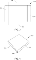
- shield casings which are also known are typically formed from a single piece of flat conductive material 512, typically metal, which is stamped, cut, or etched with four edge portions 514 bent upwards to a position perpendicular to the main surface to form sidewalls of shield casing 520 structure such as that shown in figure 4 (note that the shield casings 510 and 520 have the same functionality but have been assigned different reference numeral because of their different appearance).
- gaps 516 can exist at the corners of the casing between each adjacent sidewall which can reduce the Electromagnetic Compatibility (EMC) performance of the shield casing.
- EMC Electromagnetic Compatibility
- US 9055666 B2 relates to clip terminal soldered to and mounted on a circuit board, the terminal including a connection part bent at an angle corresponding to that of a corner of a case and at least a pair of clips connected to each other by the connection part.
- the connection part and the clips are integrated with each other.
- the connection part has a width less than or equal to that of a solder pattern of the circuit board on which the clip terminal is soldered.
- a lower end of the corner of a sidewall of the case is fitted into the clips.
- support walls are provided that uprightly protrude along an outer edge. Each support wall may have a height less that of plastic pieces that form the pair of clips.
- JP2013211294A relates to a clip terminal that includes a guide part formed along an outer contour of a corner of a shield case, and a terminal side engagement part which is formed at a part of the guide part for click fitting.
- a case side engagement part is formed which is engaged with the terminal side engagement part for click fitting, and the side surface of the shield case is click-fitted to and held on a plurality of clip terminals fixed to a circuit board.
- US 7876579 relates to an anti-electromagnetic interference (anti-EMI) corner shield unit for a shielding device.
- the shielding device is designed for fastening to a printed circuit board and includes an upper lid and a frame, and the frame includes a plurality of sequentially connected side walls with a gap left at each joint of two adjacent side walls.
- the anti-EMI corner shield unit includes an L-shaped shield plate having a first and a second shield plate for mounting to an inner side of each corner of the frame formed at the joint of any two adjacent side walls, so as to completely shield the gap left at the joint; and a clip provided at a lower edge of each of the first and the second shield plate for receiving and firmly clamping on the side wall of the frame.
- US2013148318 A1 relates to a clip terminal soldered to and mounted on a circuit board, and includes a connection part bent at an angle corresponding to that of a corner of a case and at least a pair of clips connected to each other by the connection part.
- the connection part and the clips are integrated with each other.
- the connection part has a width less than or equal to that of a solder pattern of the circuit board on which the clip terminal is soldered. A lower end of the corner of a sidewall of the case is fitted into the clips.
- JP2011198839A relates to a clip terminal, for positioning and holding a shield case, that has a side wall, which is arranged in the proximity of a side face of the shield case from outside and has a side wall with a bent portion formed so as to be a shape bent in an L shape along the side face of the shield case at the corner portion of the shield case.
- US 6051781 relates to a unitary metal clip that is stamped from a flat strip of sheet metal which is bent to provide two pairs of generally V-shaped fingers which extend upwardly from a base and have opposing apexes.
- An L-shaped arm also extends upwardly from the base between the pairs of fingers and has a horizontal pick-up tab that is located at a height above the opposing apexes of the fingers.
- a pneumatic head of an automatic pick and place machine grabs the pick-up tab and removes the clip from a pocket of a supply tape unrolled from a reel.
- the base of the clip is positioned on a solder pad of a PC board before solder re-flow.
- the lower edge of the sidewall of an EMI shield may be pressed down to bend the pick-up tab downwardly and squeeze the sidewall between the apexes of the fingers.
- the present invention provides a clip terminal according to appended claim 1.
- the first outwardly extending portion is at an angle to the second outwardly extending portion.
- the angle may be such that the first outwardly extending portion and the second outwardly extending portion form a substantially perpendicular shape corresponding to that of a corner portion of the casing.
- the shielding part may shield the corner portion of the casing.
- each of the first portion and the second portion comprise a pair of the upstanding clips.
- the shielding part also acts as a guiding member for the casing in that it enables a casing to be fed in diagonal and then in a downward direction such that the casing is aligned to sit in between the upstanding retention clips that are located on the first and second portion.
- the pair of clips are integral with the connector part and the shielding part is integral with the connector part.
- the shielding part projects upwards at an incline and not perpendicular relative to the surface of the connector part, such that the shielding part is bent inwards towards the connector part. Therefore, at least the top part of the shielding part can contact at least part of the casing to be retained by the clip terminal.
- the angle of the incline is such that the shielding part enables a gap in a corner of a casing to be substantially covered to reduce EMI entering the casing.
- the angle could be around 86 degrees relative to the surface of the connector part (which can be considered 94 degrees in the direction of bending) but the invention is not limited to this angle.
- the shielding part comprises a first shielding wall connected to an outer edge of the first outwardly extending portion of the connector part and a second shielding wall connected to the first shielding wall and having a planar surface axially aligned with an outer edge of the second outwardly extending portion of the connector part.
- the first shielding wall has an extension portion at a top end of the wall that forms a surface which can be sufficiently interacted with and picked up by a suction instrument of a conventional clip terminal mounting machine.
- the surface of the extension portion may be substantially parallel to the surface of the connector part.
- the second shielding wall has a top end which can be sufficiently gripped and picked up by a gripping instrument of a conventional clip terminal mounting machine.
- the pair of upstanding retention clips may comprise a first clip attached to an outer edge of the connector part and a second clip attached to an inner edge of the connector part, wherein at a lower portion of the pair of clips, the first clip and second clips converge towards each other, at an upper portion the first and second clips diverge away from each other, and the first and second clip are closest at a middle portion between the lower and upper portions.
- the present invention provides a clip terminal according to appended claim 9.
- the first outwardly extending portion is at an angle to the second outwardly extending portion.
- the angle may be such that the first outwardly extending portion and the second outwardly extending portion form a substantially perpendicular shape corresponding to that of a corner portion of the casing.
- the shielding part may shield a corner portion of the casing.
- each of the first portion and the second portion comprise a pair of the upstanding clips.
- the shielding part also acts as a guiding member for the casing in that it enables a casing to be fed in diagonal and then in a downward direction such that the casing is aligned to sit in between the upstanding retention clips that are located on the first and second portion.
- the pair of clips are integral with the connector part and the shielding part is integral with the connector part.
- the shielding part projects upwards at an incline and not perpendicular relative to the surface of the connector part, such that the shielding part is bent inwards towards the connector part.
- the angle of the incline is such that the shielding part enables a gap in a corner of a casing to be substantially covered to reduce EMI entering the casing.
- the angle could be around 86 degrees relative to the surface of the connector part but the invention is not limited to this angle.
- the pair of clips can be positioned on the first and / or second outwardly extending portions and have a first height relative to a surface of the connector part, and the shielding part has a second height relative to the surface of the connector part, wherein the second height is greater than the first height.
- the pair of upstanding retention clips may comprise a first clip attached to an outer edge of the connector part and a second clip attached to an inner edge of the connector part, wherein at a lower portion of the pair of clips, the first clip and second clips converge towards each other, at an upper portion the first and second clips diverge away from each other, and the first and second clip are closest at a middle portion between the lower and upper portions.
- the present invention provides a method for retaining a casing relative to a circuit board, according to appended claim 11.
- the present invention provides a method for manufacturing a clip terminal such as the clip terminal of the first aspect or second aspect, according to appended claim 12.
- a clip terminal is used to retain a shield casing (also known as a shield can) on a PCB for EMC protection.
- a clip terminal comprises shielding means to reduce a gap that may exist in one or more corners of a shield casing after the casing has been formed, for example, from a piece of stamped material.
- the clip terminal may also be formed automatically using manufacturing machinery and constructed such that it can be automatically picked and placed from a first location, for example, a tape and reel packaging, to a second location, for example, the PCB where it is to be fixed.
- the shielding means to reduce the gap is slightly inclined so that there is contact between at least a portion of the shielding means, for example, the top portion, and the shield casing.
- a clip terminal 100 according to a first embodiment of the invention will now be described with reference to Figures 4 to 11 .
- the clip terminal 100 comprises a base connector part 102 having first outwardly extending portion 104 and a second outwardly extending portion 106.
- the first outwardly extending portion 104 is at an angle to the second outwardly extending portion. The angle is such that the first outwardly extending portion and the second outwardly extending portion form a substantially perpendicular shape corresponding to that of a corner portion of a typical shield casing 520 such as that shown in figure 9 .
- the first outwardly extending portion 104 is horizontal and the second outwardly extending portion 106 is vertical thus corresponding to a corner portion of the shield casing 520.
- the angle is therefore ninety degrees but this could vary depending on the type of shield casing to be used with the clip terminal or where the clip terminal is intended to be placed relative to the casing. In some embodiments (not shown), the angle may be 180 degrees such that the first outwardly extending portion is axially aligned with the second outwardly extending portion more similar to the clip terminal arrangement shown in figure 1 .
- the clip terminal 100 further comprises one or more retention clips to provide a lateral spring force and grip side wall portions 514a, 514b (see figure 9 ) of the shield casing 520.
- a first pair 108 and a second pair 110 of retention clips are provided on the clip terminal, however, it will be appreciated to those skilled in the art with the benefit of this disclosure that any number of retention clips can be provided to grip or contact a part of a side wall of the casing 520.
- the first pair of retention clips 108 have first and second generally upstanding clip elements 112, 114 that are resilient spring portions connected to the first outwardly extending portion 104 of the connector part 102.
- the first clip element 112 is connected to an outer edge of the first outwardly extending portion 104.
- the second clip element 114 is located on an opposite side of first outwardly extending portion 104 and connected to an inner edge of the first outwardly extending portion 104.
- the first clip element 112 and second clip element 114 converge towards each other after an initial divergence adjacent the base of the connector part 102.
- the first clip element 112 and second clip element 114 diverge away from each other, and the first clip element 112 and second clip element 114 are closest at a middle portion between the lower and upper portions.
- the gripping of the side wall of the shield casing 520 can take place at the middle portion.
- the second pair of retention clips 110 have first and second generally upstanding clip elements 116, 118 that are resilient spring portions but are connected to the second outwardly extending portion 106 of the connector part 102.
- the first clip element 116 is connected to an outer edge of the second outwardly extending portion 106.
- the second clip element 118 is located on an opposite side of second outwardly extending portion 106 and connected to an inner edge of the second outwardly extending portion 106.
- the first clip element 116 and second clip element 118 converge towards each other after an initial divergence adjacent the base of the connector part 102.
- the first clip element 116 and second clip element 118 diverge away from each other, and the first clip element 116 and second clip element 118 are closest at a middle portion between the lower and upper portions.
- the gripping of the side wall of the shield casing 520 can take place at the middle portion.
- the first and second pair of retention clips 108, 110 are integral with the connection part 102 and may be formed by bending the clips upwards from the same material as the base connector part 102 into the desired shape suitable for gripping.
- gripping means may be provided instead of the specific retention clip arrangement described and may consist of any other form of resilient elements suitable for providing the required lateral spring force.
- a shielding part 130 is provided on the clip terminal.
- the shielding part 130 is located on an outer edge of the connector part for shielding a portion of the casing where there may be a gap in a wall of the casing 520.
- the shielding part 130 projects generally upwards substantially transversely relative to a planar surface of the base connector part 102.
- the shielding part 130 is integral with the connector part. It will be appreciated that the shielding part may not be integral although there are advantages to having it integral with the connector (and retention clips) and formed from the same material as the base connector part 102.
- the shielding part 130 comprises a first shielding wall 132 connected to an outer edge of the first outwardly extending portion 104 of the connector part 102 and a second shielding wall 134 that is connected to the first shielding wall 132 substantially along one longitudinal edge 132a of the first shielding wall 132 such that the second shielding wall is considered to be bent or folded along the longitudinal edge 132a towards an outer edge of the second outwardly extending portion 106 up to when it is aligned with the outer edge.
- the second shielding wall 134 is bent until it forms about a ninety degree angle with the first shielding portion 132. With this construction there may be a small gap 135 between the bottom of the second shielding wall and the outer edge of the second outwardly extending portion 106.
- the second shielding wall is connected to an outer edge of the second outwardly extending portion of the connector part.
- the shielding part 130 and particularly the first shielding wall 132 projects transversely upwards at an incline and not perpendicular relative to the surface of the connector part, such that the shielding part 130 is bent inwards towards the connector part 102. Therefore, at least the top part of the shielding part 130 can contact at least part of the corner of the shield casing 520 and to provide better shielding and retention.
- the angle of the incline is such that the shielding part enables a gap in a corner of a casing to be substantially covered to reduce EMI entering the casing.
- the angle is acute and around 86 degrees relative to the surface of the connector part 102 however the angle can vary and is not limited to 86 degrees. Looking at the angle relative to the outside of the first shielding wall and the axis of the second outwardly extending portion 106, the angle can be considered to be 94 degrees (as shown in figure 9 ).
- the first shielding wall 132 has an extension portion 136 at a top end of the wall 132 that forms a surface which can be sufficiently interacted with and picked up by a suction instrument of a conventional clip terminal mounting machine (not shown).
- the surface of the extension portion 136 may be substantially parallel to the planar surface of the connector part 102. However, it will be appreciated that such an arrangement is one example and other orientations are possible to provide a surface that enables interaction with a suction instrument.
- the second shielding wall has a top end 138 which can be sufficiently gripped and picked up by a gripping instrument of a conventional clip terminal mounting machine and therefore may not have an extension portion.
- the clip terminal can therefore be easily and automatically transported from a first location, which can be a tape and reel packaging, to a second location, which can be a PCB where it is to be fixed.
- the shielding part 130 has a height Hs greater than the heights H C of the retention clips 108, 110. This can allow easy pick and place of the clip terminal 100 in particular by having a higher point for a pick and place instrument on the top of the shielding part compared to the retention clips which will also be more difficult to pick and place due to their shape.
- the height of the first shielding wall 132 is preferably the same as the second shielding wall 134, however, in other embodiments they may be different without losing the functionality of providing extra shielding and allowing easy automatic pick and placement.
- the shield casing 520 (shown in figure 10 and 11 ) is known and in this embodiment is a conventional hollow cuboid with at least one open face so as to allow it to shield an electrical circuit on the PCB. It will be appreciated that other shield can geometries may be used with the present embodiment, for instance a hollow cube, a hollow triangular cuboid or a hollow dome shaped component could also be used, each having at least one open face so as to allow it to shield an electrical circuit on the PCB.
- the shield casing / can 520 is made from an electrically conductive material so as to protect the shielded circuit from electromagnetic interference (EMI).
- EMI electromagnetic interference
- the can has the ability to attenuate EMI and will contribute to protecting or shielding the circuit contained within it from receiving electromagnetic waves originating from outside the can (and also attenuate electromagnetic waves originating inside the can from exiting).
- the shielding part 130 of the clip terminal 100 acts as a guiding member for the casing 520 in that it enables a casing 520 to be fed in diagonal and then in a downward direction such that the casing 520 is aligned to sit in between the upstanding retention clips 108, 110 that are located on the first and second portion 104, 106.
- the shield casing 520 may be retained to a surface such as a PCB surface using the clip terminal 100 provided in this application and shield casing 520 in combination with the clip terminal 100 to be secured to the surface such as the PCB surface may not be a shield against EMI, but a cover to prevent ingress of dust or water.
- the PCB 530 comprises and is provided with electrical circuitry or some other electronic component (not shown) that requires shielding such as shielding from EMI.
- At least one clip terminal 100 but preferably a plurality of clip terminals are positioned proximal to the electrical circuitry on the PCB, such that when the casing 520 is received in the terminals 100 the casing will shield the electrical circuitry but in particular the corners of the casing 520 to prevent leakage of EMI. Therefore, the clip terminals 100 are located in a positions that are aligned with corresponding corners (not necessarily all corners) of the casing 520.
- the casing 520 is received in the clip terminal 100 to shield the electrical circuitry by positioning the casing 520 so as to abut the clip terminal 100 and in particular so as to abut the base of the clip terminal in order for the casing to be retained.
- the shielding part 130 may abut the corner of the casing 520.
- the casing 520 can thus be retained relative to the PCB 530 by the clip terminal 100.
- the pair of upstanding retention clips on the clip terminal need not take the particular form shown in figure 5 , and may consist of any other form of resilient elements suitable for providing the required lateral spring force on the internal and external surface of a side wall of a shield casing 520.
- the distance between the first clip elements and second clip elements of each pair of retention clips may vary, but will be such to allow at least the middle portion of the retention clips to contact the internal and external surface of a side wall of a shield casing 520 and the part of the retention clips to provide a retention force on the shield casing 520.
- This clips may be designed such that the distance may be adjusted to accommodate different types of shield casings or requirements of the application of the clip terminal 100.
- the design can be such to allow the retention force to be controlled to provide a high retention force for a permanent retention of the casing 520 or a low retention force for easy removal of the casing 520.
- the retention force can be controlled to provide a high retention force for a permanent retention of the casing 520 or a low retention force for easy removal of the casing 520.
- the first clip elements and second clip elements of each pair of retention clips can be made of any material so long as they are not overly flexible (unable to provide a sufficient biasing force) or overly rigid (immoveable through contact with a wall of a shield casing component).
- each clip element used in the pair to secure a component are shown as substantially the same, it will be appreciated by the skilled person that the clip element could have different styles and need not be identical in appearance.
- only one of the pair of retention clips in combination with the shielding part is provided to retain the shield casing.
- only the second clip elements 114,118 of each pair of clip elements i.e. the elements that are situated internal to the side wall of the shield casing 520
- a shielding part 130 is provided on a modified clip terminal in order to retain the shield casing 520 (for example, one or more clip elements acting on the same or different vertical side walls of the shield casing 520).
- the angle of the shielding part 130 relative to the connector part surface may be chosen to ensure contact with the external surface of the side wall of the casing 520 given that the shielding part 130 will be provided the main force for retaining the shield casing from outside the shield casing 520. It will also be appreciated that the distance between the shielding part 130 and the upstanding clips may vary depending on the forces required.
- the clip terminal could be constructed to be straight or another shape (not shown) without such an angle in which case the terminal is used with a straight edge of a shied casing rather than a corner.
- the terminal can thus be modified for use with different types of shield casings.
- clip terminals in some embodiments may be of a suitable size to be received by a printed circuit board and to receive part of a shield casing / can.
- the length of each the first and second outwardly extending portions is around least 5 cm
- the height of the shielding part is around 5 cm
- the height of the pair of upstanding clips is around 2 cm.
- Embodiments for making a clip terminal from a planar strip material will now be described. It will be appreciated that other methods of manufacturing may be used but the automated methods and apparatus disclosed herein have advantages in manufacturing such a clip terminal as disclosed herein with a complex shape and such advantages would be evident to the skilled person with the benefit of the present disclosure.
- the clip terminal 100 in one embodiment can be formed using a manufacturing apparatus including a stripper mounted overbend former assembly 200 that receives a strip 300 which is a planar material stamped or punched such that bending of one of more parts of the material will form the clip terminal 100.
- a stripper mounted overbend former assembly 200 that receives a strip 300 which is a planar material stamped or punched such that bending of one of more parts of the material will form the clip terminal 100.
- An example of one portion of the strip 300 used to make one corner clip terminal 100 is shown in figure 15 ; it will be appreciated that the strip 300 is a plurality of these portions arranged adjacent and attached to each other.
- 'Stripper' refers to the stripper plate section of the assembly and this is also referred to as a pressure plate.
- 'Overbend' refers to the forming of a part of the planar material past the required angle. The part will then spring back to the required angle.
- the amount of overbend is determined by the mechanical properties of the material. Both terms will be understood to the skilled person (in the stamping industry). In this embodiment, one method of automatically bending the material is provided.
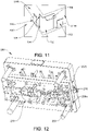
- the assembly 200 comprises at least clip overbend forming section 210 and shield overbend forming section 250.
- the clip overbend forming section 210 can be a piece of tooling that bends a part of a planar material past 90°.
- the part of the material is usually formed up to 90° by conventional swipe tooling section before entering the clip overbend forming section and the conventional swipe tooling process will not be described in detail as it will be known those in the art.
- a discussion of conventional swipe tooling is provided later (see description related to figures 19-21 ). See figure 16 which shows an example of a clip planar material from a larger strip 300 with a part 108a that is formed up to 90°, substantially perpendicular to the surface of the material.
- overbend tooling such as overbend forming section 210 forms it further so as to overbend to a position as shown by clip 108 (see figure 5 for example), that is past 90° to the surface of overbend forming section 210 (and an acute angle to the base surface of the clip 108).
- 'planar material' refers to the flat, raw material that is punched and formed and is a portion of the strip 300.
- the strip 300 moves in a direction parallel to the longitudinal axis of the assembly 200 (coaxial with the axes X-X and Y-Y shown in figures 13 and 14 respectively).
- the clip overbend forming section 210 is attached to a stripper block 200a which itself is attached to a punch block 200b.
- the clip overbend forming section comprises a plurality of formers 212, preferably two arranged opposite each other along the axis X-X, that when open, will be positioned either side of a clip 108 of clip terminal 100.
- the formers are movable in directions A and B - that is, in a direction parallel to the longitudinal axis of the assembly 200 - and will be driven together by actuators 214 from punch block 200b.
- the actuators 214 are mounted in the punch block 200b and pass through the stripper block 200a.
- the actuators 214 are movable in directions C and D - that is, in a direction substantially perpendicular to the longitudinal axis of the assembly 200 and the direction of movement of the strip 300 through the assembly 200.
- the formers 212 will open by means of two springs 218 that are in contact with the formers 212.
- Stripper block 200a will lift taking the formers 212 with it, and this will allow the strip 300 to feed and the next section of the strip 300 that requires overbending to enter the overbend forming section 210.
- the formers 212 have replaceable inserts 220 which simplify adjustment and servicing.
- the inserts 220 are the tooling parts, which make contact with the part of the planar clip material of the strip 300 to be overbent and in particular have a surface 220a on one side that is angled such that moving opposing surfaces 220a towards each other will contact the outer surfaces of clip elements 112, 114 and overbend these portions to arrive at the configuration, for example, shown in figure 5 .
- the clip 110 that is formed from bending clip elements 116 and 118 can be formed using a conventional swipe tooling and overbend tooling method and will be described later but would be understood by the skilled person and can be incorporated into the assembly 200.
- the central axis of the clip 110 coincides with the axis of movement of the strip through the assembly 200 not requiring the same configuration as the clip overbend section 210 whereas the central axis of the clip 108 is transverse or perpendicular to the axis of movement X of the strip through the assembly 200.
- the shield overbend forming section 250 similarly to the clip overbend forming section can be a piece of tooling that bends a part of a planar material past 90°, that is, past 90° to the surface of shield overbend forming section 210 (and an acute angle to the base surface of the shielding part 130)The part of the material is usually formed up to 90° by conventional swipe tooling before entering the shield overbend forming section and the conventional swipe tooling process will not be described in detail as it will be known those in the art but an example is described later.
- the section 250 comprises a former 252, preferably an inverted U-shaped single block, that when open (i.e.
- the home position of the overbend tooling assembly before it is driven forward will be positioned to the rear of the shielding part 130 (rear when following the direction of travel of the strip 300). It will then be driven forward under the extension portion 136 of the clip terminal 100 which is used as a pick and place tab, by an actuator 254 from the punch block 200b.
- the actuator is movable in direction E - that is, in a direction substantially perpendicular to the longitudinal axis of the assembly 200 and the direction of movement of the strip 300 through the assembly 200.
- the former 252 will open by means of one or more springs, preferably two springs (not shown but housed in former 252 and located either side of insert 260).
- the stripper block 200a will lift taking the former 252 with it, and this will allow the strip 300 to feed.
- the former 252 has the replaceable insert 260 which simplifies adjustment and servicing.
- the inserts 260 are the tooling parts, which make contact with the part of the clip material to be overbent.
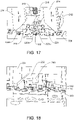
- FIG. 19 shows an example of swipe tooling section 265 where a pair of appropriate formers 266 move up from below the strip and interact with the strip to form the second pair of clips upwards to 90°. This can be achieved by pushing the clip elements 116, 118 upwards from a flat position to the 90° position relative to the strip 300 as the strip moves along the direction X.
- a similar process and machinery although not shown is used for the first pair of clips before the first pair of clips at 90° configuration enter the clip overbend forming section 210.
- Conventional overbend tooling section 270 with a pair of formers 271 is used to overbend the second pair of clips past 90° by applying a force from sides of the first and second clip elements 116, 118 to form the second pair of clips 110.
- the shielding part 130 of the planar strip material is usually formed up to 90° by conventional swipe tooling section 275 before entering the shield overbend forming section 250.
- An appropriate former 276 in the form of a member that has sufficient strength to move the strip when it interacts with it moves up from below the strip and interacts with the strip to form a bend in the portion of the strip material that corresponds to the second shielding wall 134 inwards towards the first shielding wall 132 (see right side of figure 19 ).
- swipe tooling section 277 employing conventional swipe tooling, includes a first part that is used to bend the portion of the strip material that corresponds first shielding wall 132 upwards to 90°.
- the swipe tooling section 277 then has a second part adjacent the first part that bends the portion of the strip material that corresponds extension portion 136 outwards to form the lip of the extension portion. It will be appreciated the order of the conventional strip forming and overbend forming can differ and is not limited to the order described in relation to figures 19 and 20 .
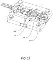
- the swipe tool section 265, overbend tooling section 270 and swipe tool section 275 are positioned after the clip overbend forming section 210 and before the shield overbend forming section 250 in the process path of the manufacturing apparatus. See figure 21 to show Z the example of where the swipe tooling and conventional overbend is located in a die section of the manufacture apparatus.
- the die section of figure 21 is typically a base section for the manufacturing apparatus and is located below the overbend forming assembly 200 shown in figure 12 . Parts of the overbend forming assembly 200 can interact with the planar strip material from above whilst parts of the die section can interact with the planar strip material from below.
- the overbend forming assembly can comprise members 216 (see figure 12 ) extending downwards perpendicular to the plane of the directional path of the strip material and that interact with the strip material from above to hold parts of the strip material in place whilst a part of the die section acts on the strip material (for example, when bending is to take place).
- members 216 see figure 12
- the overbend forming assembly can comprise members 216 (see figure 12 ) extending downwards perpendicular to the plane of the directional path of the strip material and that interact with the strip material from above to hold parts of the strip material in place whilst a part of the die section acts on the strip material (for example, when bending is to take place).
- alternative stripper mounted formers and actuators to those shown in figures 12-14 , and 17-18 may be provided in the assembly 200, as shown in figures 21 and 22 .
- two overbend formers 282a, 282b would be mounted to the stripper block 200a of figure 12 for example instead of formers 212 (see fig. 12-13 ) and are pivotable and rotational about a pivot hole or axis 283 through the formers 282a, 282b which may include an axle (not shown) or other fixed rod member that passes through both former 282a, 282b.
- the formers 282a, 282b are pivotable around the axle when a force is applied to the formers 282a, 282b from above through respective actuators 284a, 284b or some other members that are attached to the punch block 200b and move down in a direction G (that is, perpendicular to the direction of movement of the strip 300) with the punch block 200b.
- the actuators 284a, 284b interact with respective extension portion 285a, 285b of the formers 282a, 282b which cause rotational motion of the formers about the axle.
- the formers 282a, 282b also have foot portions which contact the outer surfaces of clip elements 112, 114 that are in a 90° configuration and overbend these portions to arrive at the configuration, for example, shown in figure 5
- a spring (not shown) that is located on the underside of the former would rotate the former away from the clip 108 and this will allow the strip 300 to feed.
- this modification uses rotational movement of the formers rather than lateral movement which is used in the example assembly that is used to perform the method of manufacturing covered by the appended claims, but is itself as a device not covered by the appended claims in figure 13 and 17 .
- a rotatable overbend former 292 would be mounted to the stripper block 200a in the shield overbend forming section 250 instead of formers 252 (see fig. 12 and 14 ) and would work in a similar way to the formers described in relation to figure 20 .
- the former 292 is pivotable about a pivot hole 293 through the former 292 which may include an axle (not shown) or other fixed rod member that passes through both former 292.
- the former 292 is pivotable around the axle when a force is applied to it from above through an actuator 294 or some other member that is attached to the punch block 200b and move down in a direction H (that is, perpendicular to the direction of movement of the strip 300) with the punch block 200b.
- the actuator 294 interacts with extension portion 295 of the formers 292 which causes rotational motion of the former about the axle.
- the formers 292 also has foot portions which contact the outer surface of shielding portion 130 that is in a 90° configuration and overbend this portion to arrive at the configuration, for example, shown in figure 5 .
- a spring (not shown) that is located on the underside of the former would rotate the former away from the shielding part 130 and this will allow the strip 300 to feed.
- this modification uses rotational movement of the formers rather than lateral movement which is used in the example assembly that is used to perform the method of manufacturing covered by the appended claims, but is itself a device that is not covered by the appended claims in figure 14 and 18 .
- the overbend section can be positioned on top of the die section which can form a base for the overbend section of figure 12 .
- a planar strip 300 is provided which is a single planar material having at least one portion such as that shown in figure 15 that forms a corner clip terminal 100.
- the planar strip is created with stamped and / or punched sections that are to be bent and / or cut during the manufacturing process accordingly to form the clip terminal 100.
- the planar strip can be moved along a pathway of the manufacturing apparatus which includes the assembly 200 that comprises at least the clip overbend forming section 210 and the shield overbend forming section 250.
- the pathway is generally parallel to the longitudinal axis of the second outwardly extending part 106 of the planar material that forms the clip terminal 100 (or from another reference point, generally parallel to the central axis of the second pair of clips 110) and generally perpendicular to the longitudinal axis of the first outwardly extending part 104 of the planar material that forms the clip terminal 100 (or from another reference point, generally perpendicular to the central axis of the first pair of clips 108).
- step 410 the first pair of clips on the first outwardly extending part 104 are bent upwards towards each other to be substantially formed to 90° to the surface of the first outwardly extending part of the strip material in an upstanding configuration 108a (see figure 16 ).
- step 415 the first pair of clips formed in step 410 move to the clip overbend forming section 210 to be overbent as described in one example in relation to apparatus in figures 13 and 17 .
- step 420 the strip portion with the overbent first pair of clips 108 moves to a section such as a conventional swipe tooling section (see figure 19 ) that bends upwards at substantially 90° to the surface the second pair of clips 110 and then overbends to an overbent configuration to a similar extent to the first pair of clips 108 (also see figure 18 showing that the second pair of clips are already formed).
- a section such as a conventional swipe tooling section (see figure 19 ) that bends upwards at substantially 90° to the surface the second pair of clips 110 and then overbends to an overbent configuration to a similar extent to the first pair of clips 108 (also see figure 18 showing that the second pair of clips are already formed).
- the portion of the strip material including the formed first pair of clips 108 and second pair of clips 110 moves to a section where the portions of the strip material that correspond to the shielding part 130 are formed into shape to 90° to the surface of the strip material.
- This can be achieved in a conventional way by bending the portion of the strip material that corresponds second shielding wall 134 inwards towards the first shielding wall 132, bending the portion of the strip material that corresponds first shielding wall 132 upwards, and bending the portion of the strip material that corresponds extension portion 136 outwards to form the lip on the first shielding wall 132.
- the shielding part in this configuration is at up to 90° to the surface of the strip material.
- An example of the process is shown in figure 19 and 20 described above.
- step 430 the portion of strip material formed in step 425 moves to the shield overbend forming section 210 to overbend the shielding part 130 as described in one example in relation to apparatus in figures 14 and 18 .
Landscapes
- Engineering & Computer Science (AREA)
- Microelectronics & Electronic Packaging (AREA)
- Manufacturing & Machinery (AREA)
- Shielding Devices Or Components To Electric Or Magnetic Fields (AREA)
- Manufacturing Of Electrical Connectors (AREA)
- Coupling Device And Connection With Printed Circuit (AREA)
Claims (18)
- Borne à pince (100) destinée à retenir de manière fixe un boîtier (520), la borne à pince (100) étant appropriée pour être montée sur une carte de circuit imprimé (530), la borne à pince (100) comprenant :une pièce de connecteur (102) présentant une première portion s'étendant vers l'extérieur (104) et une seconde portion s'étendant vers l'extérieur (106) ;au moins une pince de retenue verticale (108, 110) destinée à saisir une portion de paroi latérale (514) d'un boîtier (520), dans laquelle la pince de retenue verticale (108, 110) est positionnée sur les première ou seconde parties s'étendant vers l'extérieur (104, 106) et présente une première hauteur par rapport à une surface de la pièce de connecteur (102) ; etune pièce de protection (130) située sur un bord extérieur de la pièce de connecteur (102) pour protéger une portion du boîtier (520), la pièce de protection (130) faisant saillie vers le haut par rapport à la surface de la pièce de connecteur (102) et ayant une seconde hauteur par rapport à la surface de la pièce de connecteur (102),dans laquelle la seconde hauteur est supérieure à la première hauteur, caractérisée en ce que la pièce de protection (130) fait saillie vers le haut selon une inclinaison par rapport à la surface de la pièce de connecteur (102), de telle sorte que la pièce de protection (130) est pliée vers l'intérieur en direction de la pièce de connecteur (102), et l'angle de l'inclinaison est tel qu'un espace (516) dans un boîtier (520) est sensiblement couvert de façon à réduire les interférences électromagnétiques entrant dans le boîtier (520) ou la poussière ou l'eau entrant dans le boîtier (520).
- Borne à pince (100) selon la revendication 1, dans laquelle la première portion s'étendant vers l'extérieur (104) est selon un angle avec la seconde portion s'étendant vers l'extérieur (106) et dans laquelle l'angle est tel que la première portion s'étendant vers l'extérieur (104) et la seconde portion s'étendant vers l'extérieur (106) forment une forme sensiblement perpendiculaire correspondant à celle d'une portion de coin du boîtier (520), et la pièce de protection (130) est configurée de façon à protéger la portion de coin du boîtier (520).
- Borne à pince (100) selon la revendication 1 ou 2, dans laquelle il y a au moins une paire de pinces de retenue verticales (108, 110) positionnées sur les première et/ou seconde portions s'étendant vers l'extérieur (104, 106).
- Borne à pince (100) selon une quelconque revendication précédente, dans laquelle la pince de retenue verticale (108) ou la paire de pinces de retenue verticales (108, 110) est/sont solidaire(s) de la pièce de connecteur (102) et/ou dans laquelle la pièce de protection (130) est solidaire de la pièce de connecteur (102).
- Borne à pince (100) selon une quelconque revendication précédente, dans laquelle au moins la partie supérieure de la pièce de protection (130) est agencée de façon à venir en contact avec au moins une partie du boîtier (520) pour être retenue par la borne à pince (100).
- Borne à pince (100) selon une quelconque revendication précédente, dans laquelle la pièce de protection (130) comprend une première paroi de protection (132) raccordée à un bord extérieur de la première portion s'étendant vers l'extérieur (104) de la pièce de connecteur (102) et une seconde paroi de protection (134) raccordée à la première paroi de protection (132) et facultativement dans laquelle la seconde paroi de protection (134) présente une surface plane alignée axialement avec au moins une partie d'un bord extérieur de la seconde portion s'étendant vers l'extérieur (106) de la pièce de connecteur (102).
- Borne à pince (100) selon une quelconque revendication précédente, dans laquelle la pièce de protection (130) comprend une portion d'extension (136) au niveau d'une extrémité supérieure qui forme une surface qui peut suffisamment être mise en interaction avec un instrument d'aspiration et ramassée par celui-ci et/ou la pièce de protection (130) présente une extrémité supérieure qui peut suffisamment être saisie et ramassée par un instrument de saisie.
- Borne à pince (100) selon la revendication 7, dans laquelle la surface de la portion d'extension (136) est sensiblement parallèle à la surface de la pièce de connecteur (102).
- Borne à pince (100) destinée à retenir de manière fixe un boîtier (520), la borne à pince (100) étant appropriée pour être montée sur une carte de circuit imprimé (530), la borne à pince (100) comprenant :une pièce de connecteur (102) présentant une première portion s'étendant vers l'extérieur (104) et une seconde portion s'étendant vers l'extérieur (106) ;au moins une pince de retenue verticale (108, 110) destinée à saisir une portion de paroi latérale (514) d'un boîtier (520), dans laquelle la pince de retenue verticale (108, 110) est positionnée sur les première ou seconde parties s'étendant vers l'extérieur (104, 106) ;une pièce de protection (130) située sur un bord extérieur de la pièce de connecteur (102) pour protéger une portion du boîtier (520), la pièce de protection (130) faisant saillie vers le haut par rapport à la surface de la pièce de connecteur (102),la pièce de protection (130) comprenant une portion d'extension (136) au niveau d'une extrémité supérieure qui forme une surface qui peut suffisamment être mise en interaction avec un instrument d'aspiration et ramassée par celui-ci, caractérisée en ce que la pièce de protection (130) fait saillie vers le haut selon une inclinaison par rapport à la surface de la pièce de connecteur (102), de telle sorte que la pièce de protection (130) est pliée vers l'intérieur en direction de la pièce de connecteur (102), et l'angle de l'inclinaison est tel qu'un espace (516) dans un boîtier (520) est sensiblement couvert de façon à réduire les interférences électromagnétiques entrant dans le boîtier (520) ou la poussière ou l'eau entrant dans le boîtier (520).
- Borne à pince (100) selon la revendication 9, dans laquelle la pièce de protection (130) comprend une première paroi de protection (132) raccordée à un bord extérieur de la première portion s'étendant vers l'extérieur (104) de la pièce de connecteur (102) et une seconde paroi de protection (134) raccordée à la première paroi de protection (132) et facultativement dans laquelle la seconde paroi de protection (134) présente une surface plane alignée axialement avec au moins une partie d'un bord extérieur de la seconde portion s'étendant vers l'extérieur (106) de la pièce de connecteur (102).
- Procédé de retenue d'un boîtier (520) par rapport à une carte de circuit imprimé (530) comprenant :la fourniture d'une carte de circuit imprimé (530) avec un circuit électrique ;la fourniture d'au moins une borne à pince (100) selon une quelconque revendication précédente dans une position proximale par rapport au circuit électrique sur la carte de circuit imprimé (530) ; etla réception dans la borne à pince (100) d'un boîtier (520) pour protéger le circuit électrique en positionnant le boîtier (520) de manière à venir en butée contre la borne à pince (100) afin de retenir le boîtier (520) dans une position par rapport au circuit.
- Procédé de formation d'une borne à clip (100) selon l'une quelconque des revendications 1 à 10, comprenant :la formation (400) d'un matériau en bande plan (300) comprenant des sections estampées à former dans au moins une pince de retenue verticale (108, 110) afin de saisir une portion de paroi latérale (514) d'un boîtier (520), et dans au moins une pièce de protection (130) ;le pliage vers le haut d'une section des sections estampées correspondant à l'au moins une pince de retenue verticale (108, 110) ;le pliage vers le haut d'une section des sections estampées correspondant à l'au moins une pièce de protection (130) ; etle retrait (435) de parties du matériau en bande plan (300) pour produire ainsi une borne à pince (100) comprenant au moins une pince de retenue verticale (108, 110) et au moins une pièce de protection (130),dans lequel l'étape de pliage de la section des sections estampées correspondant à la pièce de protection (130) comprend en outre le pliage (425) vers le haut de la pièce de protection (130) à former à sensiblement 90° par rapport à la surface du matériau en bande plan (300), puis le pliage avec compensation (430) de la pièce de protection (130) au-delà de sensiblement 90°.
- Procédé selon la revendication 12, dans lequel la section correspondant à l'au moins une pince de retenue verticale (108, 110) est raccordée à la première portion s'étendant vers l'extérieur (104) dans le matériau en bande plan (300), et l'étape de pliage de la section des sections estampées correspondant à l'au moins une pince de retenue verticale (108, 110) comprend en outre le pliage (410) vers le haut de la pince de retenue verticale (108, 110) à former à sensiblement 90° par rapport à la surface de la première portion s'étendant vers l'extérieur (104) du matériau en bande (300), puis le pliage avec compensation (415) de l'au moins une pince de retenue verticale (108,110) au-delà de sensiblement 90°.
- Procédé selon la revendication 12 ou 13, dans lequel la section correspondant à une seconde pince de retenue verticale (110) est raccordée à la seconde portion s'étendant vers l'extérieur (106) dans le matériau en bande plan (300).
- Procédé selon la revendication 12, dans lequel l'étape de pliage vers le haut de la section des sections estampées correspondant à l'au moins une pince de retenue verticale (108, 110) comprend :le pliage d'une première section de pince de retenue verticale (108) d'un matériau en bande plan (300) pour former une première pince de retenue verticale (108) présentant un axe central ;le déplacement de la première pince de retenue verticale (108) le long d'une trajectoire directionnelle avec un axe qui est sensiblement perpendiculaire à l'axe central ;le pliage avec compensation de la première pince de retenue verticale (108) par l'intermédiaire d'un premier mécanisme de pliage avec compensation (210) qui interagit avec la première pince de retenue verticale (108) depuis le dessus etfournit une force dans une direction qui est sensiblement parallèle à l'axe de la trajectoire de telle sorte que la pince de retenue verticale (108) est pliée vers l'intérieur.
- Procédé selon la revendication 15, dans lequel l'étape de pliage vers le haut de la section des sections estampées correspondant à l'au moins une pièce de protection (130) comprend en outre :le pliage d'une section de protection d'un matériau en bande plan (300) pour former une pièce de protection verticale (130), la pièce de protection (130) présentant un axe longitudinal qui est sensiblement perpendiculaire à la surface du matériau en bande plan (300) ;le déplacement de la pièce de protection verticale (130) formée le long de la trajectoire directionnelle ; et le pliage avec compensation de la pièce de protection (130) au-delà de sensiblement 90° comprend en outre :le pliage avec compensation de la pièce de protection verticale (130) formée par l'intermédiaire d'un second mécanisme de pliage avec compensation (250) qui interagit avec la pièce de protection (130) depuis le dessus et fournit une force dans une direction qui est sensiblement parallèle à l'axe de trajectoire de telle sorte que la pièce de protection (130) est pliée vers l'intérieur.
- Procédé selon les revendications 15 ou 16, dans lequel le procédé comprend en outre :le pliage d'une seconde section de pince de retenue verticale (108, 110) d'un matériau en bande plan (300) pour former une seconde pince de retenue verticale (108, 110) présentant un axe central ;le déplacement de la seconde pince de retenue verticale (108, 110) formée le long d'une trajectoire directionnelle avec un axe qui est sensiblement parallèle à l'axe central ;le pliage avec compensation de la seconde pince de retenue verticale (108, 110) formée par l'intermédiaire d'un second mécanisme de pliage avec compensation qui interagit avec la seconde pince de retenue verticale (108, 110) depuis le dessus et fournit une force dans une direction qui est sensiblement perpendiculaire à l'axe de trajectoire de telle sorte que la pince de retenue verticale (108, 110) est pliée vers l'intérieur.
- Procédé selon l'une quelconque des revendications 15 à 17, dans lequel le premier mécanisme de pliage avec compensation comprend au moins un gabarit (212) qui est mobile dans une direction sensiblement parallèle à la trajectoire directionnelle et/ou autour d'un axe de rotation et facultativement dans lequel le premier mécanisme de pliage avec compensation comprend en outre au moins un actionneur (214) qui entraîne les gabarits dans la direction sensiblement parallèle.
Applications Claiming Priority (1)
| Application Number | Priority Date | Filing Date | Title |
|---|---|---|---|
| GB1815992.1A GB2577684A (en) | 2018-10-01 | 2018-10-01 | Terminal and method for retaining a component to a surface, and manufacturing method and apparatus |
Publications (3)
| Publication Number | Publication Date |
|---|---|
| EP3634097A2 EP3634097A2 (fr) | 2020-04-08 |
| EP3634097A3 EP3634097A3 (fr) | 2020-07-22 |
| EP3634097B1 true EP3634097B1 (fr) | 2022-10-26 |
Family
ID=68109179
Family Applications (1)
| Application Number | Title | Priority Date | Filing Date |
|---|---|---|---|
| EP19200737.5A Active EP3634097B1 (fr) | 2018-10-01 | 2019-10-01 | Terminal et procédé pour retenir un composant sur une surface et procédé et appareil de fabrication |
Country Status (4)
| Country | Link |
|---|---|
| US (1) | US10869416B2 (fr) |
| EP (1) | EP3634097B1 (fr) |
| ES (1) | ES2933819T3 (fr) |
| GB (1) | GB2577684A (fr) |
Families Citing this family (3)
| Publication number | Priority date | Publication date | Assignee | Title |
|---|---|---|---|---|
| WO2023277902A1 (fr) * | 2021-06-30 | 2023-01-05 | Hewlett-Packard Development Company, L.P. | Pinces de blindage |
| CN116014517A (zh) | 2021-10-21 | 2023-04-25 | 苏州力特奥维斯保险丝有限公司 | 带有pdm外壳支撑件的跳线汇流条 |
| US20240389289A1 (en) * | 2023-05-17 | 2024-11-21 | Intel Corporation | Apparatus and system of electromagnetic interference (emi) shielding |
Family Cites Families (13)
| Publication number | Priority date | Publication date | Assignee | Title |
|---|---|---|---|---|
| JPH0710998A (ja) * | 1993-06-25 | 1995-01-13 | Asahi Glass Co Ltd | 親水性多孔膜の製造方法 |
| JPH0710998U (ja) | 1993-07-02 | 1995-02-14 | 幸夫 城尾 | 電磁波遮断機能を有する電子回路用カバー |
| US6051781A (en) | 1997-09-24 | 2000-04-18 | Autosplice, Inc. | Surface mount electromagnetic frequency interference shield clip |
| JP2000196280A (ja) * | 1998-12-25 | 2000-07-14 | Autosplice Inc | 電磁気周波数妨害シ―ルド用の面着式クリップ |
| CN201029127Y (zh) * | 2007-03-09 | 2008-02-27 | 富士康(昆山)电脑接插件有限公司 | 电连接器 |
| US7876579B1 (en) * | 2009-09-23 | 2011-01-25 | Ezconn Corporation | Anti-electromagnetic interference corner shield unit for a shielding device |
| JP5566142B2 (ja) * | 2010-03-17 | 2014-08-06 | オートスプライス株式会社 | クリップ端子 |
| US8188381B2 (en) * | 2010-05-06 | 2012-05-29 | Avago Technologies Fiber Ip (Singapore) Pte. Ltd. | Mid-board module retention and EMI cage |
| JP5467469B2 (ja) | 2011-01-04 | 2014-04-09 | 山栄化学株式会社 | プリント配線基板に表面実装する方法 |
| WO2013085123A1 (fr) * | 2011-12-09 | 2013-06-13 | 조인셋 주식회사 | Terminal enclipsable de fixation de boîtier et dispositif de blindage emi utilisant celui-ci |
| JP2013211294A (ja) * | 2012-03-30 | 2013-10-10 | Auto Splice Kk | シールドケース組立体 |
| CN105246316B (zh) * | 2015-11-11 | 2018-09-14 | 中磊电子(苏州)有限公司 | 遮罩夹与通信装置 |
| CN205546409U (zh) * | 2016-02-01 | 2016-08-31 | 富士康(昆山)电脑接插件有限公司 | 屏蔽夹及其屏蔽装置 |
-
2018
- 2018-10-01 GB GB1815992.1A patent/GB2577684A/en not_active Withdrawn
-
2019
- 2019-09-30 US US16/587,526 patent/US10869416B2/en active Active
- 2019-10-01 EP EP19200737.5A patent/EP3634097B1/fr active Active
- 2019-10-01 ES ES19200737T patent/ES2933819T3/es active Active
Also Published As
| Publication number | Publication date |
|---|---|
| US10869416B2 (en) | 2020-12-15 |
| GB2577684A (en) | 2020-04-08 |
| US20200107477A1 (en) | 2020-04-02 |
| EP3634097A2 (fr) | 2020-04-08 |
| EP3634097A3 (fr) | 2020-07-22 |
| ES2933819T3 (es) | 2023-02-14 |
Similar Documents
| Publication | Publication Date | Title |
|---|---|---|
| EP3634097B1 (fr) | Terminal et procédé pour retenir un composant sur une surface et procédé et appareil de fabrication | |
| US9055666B2 (en) | Clip terminal for fixing case and shield apparatus using the same | |
| CN109659723B (zh) | 电连接器及其制造方法 | |
| WO2010135540A1 (fr) | Connecteur carte à carte | |
| CN105265033B (zh) | 电磁波屏蔽构造 | |
| US11903177B2 (en) | Board level shield (BLS) frames including pickup members with pickup areas rotatable in place when drawn | |
| EP2415126B1 (fr) | Connecteur blindé avec positionnement du blindage amélioré | |
| US9437945B2 (en) | Electrical connector with improved terminal | |
| JP3851526B2 (ja) | アースターミナル | |
| CN100521406C (zh) | 电连接器的组装方法 | |
| JP2009117773A (ja) | 電子機器 | |
| JP2000196280A (ja) | 電磁気周波数妨害シ―ルド用の面着式クリップ | |
| JP6020509B2 (ja) | 回路基板接続用ターミナル | |
| EP4148915A1 (fr) | Appareil de connexion électrique, procédé de fabrication et dispositif informatique | |
| JP2006012886A (ja) | シールド構造 | |
| KR101318944B1 (ko) | 케이스 고정용 클립 단자 | |
| KR101151689B1 (ko) | 전자파 차폐 케이스 고정용 클립 및 이를 적용한 전자파 차폐장치 | |
| CN102811593B (zh) | 电路基板 | |
| TW202249585A (zh) | 表面安裝屏蔽罩組件及屏蔽罩用表面安裝單向定位件 | |
| CN217011623U (zh) | 主板组件及终端设备 | |
| KR101727994B1 (ko) | 측면 실장형 컨텍트와 그 결합구조 | |
| KR20140064160A (ko) | 인쇄회로기판용 고정클립 및 이를 이용한 차폐장치 | |
| CN215683114U (zh) | 表面安装屏蔽罩组件及屏蔽罩用表面安装单向定位件 | |
| CN2629275Y (zh) | 电连接器 | |
| CN2593405Y (zh) | 具有遮蔽装置的电连接器 |
Legal Events
| Date | Code | Title | Description |
|---|---|---|---|
| PUAI | Public reference made under article 153(3) epc to a published international application that has entered the european phase |
Free format text: ORIGINAL CODE: 0009012 |
|
| STAA | Information on the status of an ep patent application or granted ep patent |
Free format text: STATUS: THE APPLICATION HAS BEEN PUBLISHED |
|
| AK | Designated contracting states |
Kind code of ref document: A2 Designated state(s): AL AT BE BG CH CY CZ DE DK EE ES FI FR GB GR HR HU IE IS IT LI LT LU LV MC MK MT NL NO PL PT RO RS SE SI SK SM TR |
|
| AX | Request for extension of the european patent |
Extension state: BA ME |
|
| PUAL | Search report despatched |
Free format text: ORIGINAL CODE: 0009013 |
|
| AK | Designated contracting states |
Kind code of ref document: A3 Designated state(s): AL AT BE BG CH CY CZ DE DK EE ES FI FR GB GR HR HU IE IS IT LI LT LU LV MC MK MT NL NO PL PT RO RS SE SI SK SM TR |
|
| AX | Request for extension of the european patent |
Extension state: BA ME |
|
| RIC1 | Information provided on ipc code assigned before grant |
Ipc: H05K 9/00 20060101AFI20200617BHEP |
|
| STAA | Information on the status of an ep patent application or granted ep patent |
Free format text: STATUS: REQUEST FOR EXAMINATION WAS MADE |
|
| 17P | Request for examination filed |
Effective date: 20200909 |
|
| RBV | Designated contracting states (corrected) |
Designated state(s): AL AT BE BG CH CY CZ DE DK EE ES FI FR GB GR HR HU IE IS IT LI LT LU LV MC MK MT NL NO PL PT RO RS SE SI SK SM TR |
|
| GRAP | Despatch of communication of intention to grant a patent |
Free format text: ORIGINAL CODE: EPIDOSNIGR1 |
|
| STAA | Information on the status of an ep patent application or granted ep patent |
Free format text: STATUS: GRANT OF PATENT IS INTENDED |
|
| INTG | Intention to grant announced |
Effective date: 20220520 |
|
| GRAS | Grant fee paid |
Free format text: ORIGINAL CODE: EPIDOSNIGR3 |
|
| GRAA | (expected) grant |
Free format text: ORIGINAL CODE: 0009210 |
|
| STAA | Information on the status of an ep patent application or granted ep patent |
Free format text: STATUS: THE PATENT HAS BEEN GRANTED |
|
| AK | Designated contracting states |
Kind code of ref document: B1 Designated state(s): AL AT BE BG CH CY CZ DE DK EE ES FI FR GB GR HR HU IE IS IT LI LT LU LV MC MK MT NL NO PL PT RO RS SE SI SK SM TR |
|
| REG | Reference to a national code |
Ref country code: GB Ref legal event code: FG4D |
|
| REG | Reference to a national code |
Ref country code: CH Ref legal event code: EP |
|
| REG | Reference to a national code |
Ref country code: DE Ref legal event code: R096 Ref document number: 602019021030 Country of ref document: DE |
|
| REG | Reference to a national code |
Ref country code: AT Ref legal event code: REF Ref document number: 1528055 Country of ref document: AT Kind code of ref document: T Effective date: 20221115 |
|
| REG | Reference to a national code |
Ref country code: IE Ref legal event code: FG4D |
|
| REG | Reference to a national code |
Ref country code: SE Ref legal event code: TRGR |
|
| REG | Reference to a national code |
Ref country code: LT Ref legal event code: MG9D |
|
| REG | Reference to a national code |
Ref country code: ES Ref legal event code: FG2A Ref document number: 2933819 Country of ref document: ES Kind code of ref document: T3 Effective date: 20230214 |
|
| REG | Reference to a national code |
Ref country code: NL Ref legal event code: MP Effective date: 20221026 |
|
| REG | Reference to a national code |
Ref country code: AT Ref legal event code: MK05 Ref document number: 1528055 Country of ref document: AT Kind code of ref document: T Effective date: 20221026 |
|
| PG25 | Lapsed in a contracting state [announced via postgrant information from national office to epo] |
Ref country code: NL Free format text: LAPSE BECAUSE OF FAILURE TO SUBMIT A TRANSLATION OF THE DESCRIPTION OR TO PAY THE FEE WITHIN THE PRESCRIBED TIME-LIMIT Effective date: 20221026 |
|
| PG25 | Lapsed in a contracting state [announced via postgrant information from national office to epo] |
Ref country code: PT Free format text: LAPSE BECAUSE OF FAILURE TO SUBMIT A TRANSLATION OF THE DESCRIPTION OR TO PAY THE FEE WITHIN THE PRESCRIBED TIME-LIMIT Effective date: 20230227 Ref country code: NO Free format text: LAPSE BECAUSE OF FAILURE TO SUBMIT A TRANSLATION OF THE DESCRIPTION OR TO PAY THE FEE WITHIN THE PRESCRIBED TIME-LIMIT Effective date: 20230126 Ref country code: LT Free format text: LAPSE BECAUSE OF FAILURE TO SUBMIT A TRANSLATION OF THE DESCRIPTION OR TO PAY THE FEE WITHIN THE PRESCRIBED TIME-LIMIT Effective date: 20221026 Ref country code: FI Free format text: LAPSE BECAUSE OF FAILURE TO SUBMIT A TRANSLATION OF THE DESCRIPTION OR TO PAY THE FEE WITHIN THE PRESCRIBED TIME-LIMIT Effective date: 20221026 Ref country code: AT Free format text: LAPSE BECAUSE OF FAILURE TO SUBMIT A TRANSLATION OF THE DESCRIPTION OR TO PAY THE FEE WITHIN THE PRESCRIBED TIME-LIMIT Effective date: 20221026 |
|
| PG25 | Lapsed in a contracting state [announced via postgrant information from national office to epo] |
Ref country code: RS Free format text: LAPSE BECAUSE OF FAILURE TO SUBMIT A TRANSLATION OF THE DESCRIPTION OR TO PAY THE FEE WITHIN THE PRESCRIBED TIME-LIMIT Effective date: 20221026 Ref country code: PL Free format text: LAPSE BECAUSE OF FAILURE TO SUBMIT A TRANSLATION OF THE DESCRIPTION OR TO PAY THE FEE WITHIN THE PRESCRIBED TIME-LIMIT Effective date: 20221026 Ref country code: LV Free format text: LAPSE BECAUSE OF FAILURE TO SUBMIT A TRANSLATION OF THE DESCRIPTION OR TO PAY THE FEE WITHIN THE PRESCRIBED TIME-LIMIT Effective date: 20221026 Ref country code: IS Free format text: LAPSE BECAUSE OF FAILURE TO SUBMIT A TRANSLATION OF THE DESCRIPTION OR TO PAY THE FEE WITHIN THE PRESCRIBED TIME-LIMIT Effective date: 20230226 Ref country code: HR Free format text: LAPSE BECAUSE OF FAILURE TO SUBMIT A TRANSLATION OF THE DESCRIPTION OR TO PAY THE FEE WITHIN THE PRESCRIBED TIME-LIMIT Effective date: 20221026 Ref country code: GR Free format text: LAPSE BECAUSE OF FAILURE TO SUBMIT A TRANSLATION OF THE DESCRIPTION OR TO PAY THE FEE WITHIN THE PRESCRIBED TIME-LIMIT Effective date: 20230127 |
|
| REG | Reference to a national code |
Ref country code: DE Ref legal event code: R097 Ref document number: 602019021030 Country of ref document: DE |
|
| PG25 | Lapsed in a contracting state [announced via postgrant information from national office to epo] |
Ref country code: SM Free format text: LAPSE BECAUSE OF FAILURE TO SUBMIT A TRANSLATION OF THE DESCRIPTION OR TO PAY THE FEE WITHIN THE PRESCRIBED TIME-LIMIT Effective date: 20221026 Ref country code: RO Free format text: LAPSE BECAUSE OF FAILURE TO SUBMIT A TRANSLATION OF THE DESCRIPTION OR TO PAY THE FEE WITHIN THE PRESCRIBED TIME-LIMIT Effective date: 20221026 Ref country code: EE Free format text: LAPSE BECAUSE OF FAILURE TO SUBMIT A TRANSLATION OF THE DESCRIPTION OR TO PAY THE FEE WITHIN THE PRESCRIBED TIME-LIMIT Effective date: 20221026 Ref country code: DK Free format text: LAPSE BECAUSE OF FAILURE TO SUBMIT A TRANSLATION OF THE DESCRIPTION OR TO PAY THE FEE WITHIN THE PRESCRIBED TIME-LIMIT Effective date: 20221026 Ref country code: CZ Free format text: LAPSE BECAUSE OF FAILURE TO SUBMIT A TRANSLATION OF THE DESCRIPTION OR TO PAY THE FEE WITHIN THE PRESCRIBED TIME-LIMIT Effective date: 20221026 |
|
| PG25 | Lapsed in a contracting state [announced via postgrant information from national office to epo] |
Ref country code: SK Free format text: LAPSE BECAUSE OF FAILURE TO SUBMIT A TRANSLATION OF THE DESCRIPTION OR TO PAY THE FEE WITHIN THE PRESCRIBED TIME-LIMIT Effective date: 20221026 Ref country code: AL Free format text: LAPSE BECAUSE OF FAILURE TO SUBMIT A TRANSLATION OF THE DESCRIPTION OR TO PAY THE FEE WITHIN THE PRESCRIBED TIME-LIMIT Effective date: 20221026 |
|
| PLBE | No opposition filed within time limit |
Free format text: ORIGINAL CODE: 0009261 |
|
| STAA | Information on the status of an ep patent application or granted ep patent |
Free format text: STATUS: NO OPPOSITION FILED WITHIN TIME LIMIT |
|
| 26N | No opposition filed |
Effective date: 20230727 |
|
| PG25 | Lapsed in a contracting state [announced via postgrant information from national office to epo] |
Ref country code: SI Free format text: LAPSE BECAUSE OF FAILURE TO SUBMIT A TRANSLATION OF THE DESCRIPTION OR TO PAY THE FEE WITHIN THE PRESCRIBED TIME-LIMIT Effective date: 20221026 |
|
| PG25 | Lapsed in a contracting state [announced via postgrant information from national office to epo] |
Ref country code: MC Free format text: LAPSE BECAUSE OF FAILURE TO SUBMIT A TRANSLATION OF THE DESCRIPTION OR TO PAY THE FEE WITHIN THE PRESCRIBED TIME-LIMIT Effective date: 20221026 |
|
| REG | Reference to a national code |
Ref country code: BE Ref legal event code: MM Effective date: 20231031 |
|
| PG25 | Lapsed in a contracting state [announced via postgrant information from national office to epo] |
Ref country code: LU Free format text: LAPSE BECAUSE OF NON-PAYMENT OF DUE FEES Effective date: 20231001 |
|
| PG25 | Lapsed in a contracting state [announced via postgrant information from national office to epo] |
Ref country code: LU Free format text: LAPSE BECAUSE OF NON-PAYMENT OF DUE FEES Effective date: 20231001 |
|
| PG25 | Lapsed in a contracting state [announced via postgrant information from national office to epo] |
Ref country code: BE Free format text: LAPSE BECAUSE OF NON-PAYMENT OF DUE FEES Effective date: 20231031 |
|
| PG25 | Lapsed in a contracting state [announced via postgrant information from national office to epo] |
Ref country code: BG Free format text: LAPSE BECAUSE OF FAILURE TO SUBMIT A TRANSLATION OF THE DESCRIPTION OR TO PAY THE FEE WITHIN THE PRESCRIBED TIME-LIMIT Effective date: 20221026 |
|
| PG25 | Lapsed in a contracting state [announced via postgrant information from national office to epo] |
Ref country code: BG Free format text: LAPSE BECAUSE OF FAILURE TO SUBMIT A TRANSLATION OF THE DESCRIPTION OR TO PAY THE FEE WITHIN THE PRESCRIBED TIME-LIMIT Effective date: 20221026 |
|
| PG25 | Lapsed in a contracting state [announced via postgrant information from national office to epo] |
Ref country code: CY Free format text: LAPSE BECAUSE OF FAILURE TO SUBMIT A TRANSLATION OF THE DESCRIPTION OR TO PAY THE FEE WITHIN THE PRESCRIBED TIME-LIMIT; INVALID AB INITIO Effective date: 20191001 |
|
| PG25 | Lapsed in a contracting state [announced via postgrant information from national office to epo] |
Ref country code: HU Free format text: LAPSE BECAUSE OF FAILURE TO SUBMIT A TRANSLATION OF THE DESCRIPTION OR TO PAY THE FEE WITHIN THE PRESCRIBED TIME-LIMIT; INVALID AB INITIO Effective date: 20191001 |
|
| PGFP | Annual fee paid to national office [announced via postgrant information from national office to epo] |
Ref country code: TR Payment date: 20250930 Year of fee payment: 7 Ref country code: IT Payment date: 20250922 Year of fee payment: 7 |
|
| PGFP | Annual fee paid to national office [announced via postgrant information from national office to epo] |
Ref country code: GB Payment date: 20250911 Year of fee payment: 7 |
|
| PGFP | Annual fee paid to national office [announced via postgrant information from national office to epo] |
Ref country code: FR Payment date: 20250908 Year of fee payment: 7 |
|
| PGFP | Annual fee paid to national office [announced via postgrant information from national office to epo] |
Ref country code: SE Payment date: 20250910 Year of fee payment: 7 |
|
| PGFP | Annual fee paid to national office [announced via postgrant information from national office to epo] |
Ref country code: IE Payment date: 20250909 Year of fee payment: 7 |
|
| REG | Reference to a national code |
Ref country code: CH Ref legal event code: U11 Free format text: ST27 STATUS EVENT CODE: U-0-0-U10-U11 (AS PROVIDED BY THE NATIONAL OFFICE) Effective date: 20251101 |
|
| PGFP | Annual fee paid to national office [announced via postgrant information from national office to epo] |
Ref country code: DE Payment date: 20250910 Year of fee payment: 7 |
|
| PGFP | Annual fee paid to national office [announced via postgrant information from national office to epo] |
Ref country code: CH Payment date: 20251101 Year of fee payment: 7 |
|
| PGFP | Annual fee paid to national office [announced via postgrant information from national office to epo] |
Ref country code: ES Payment date: 20251107 Year of fee payment: 7 |