EP3634193B1 - Bodendüsenvorrichtung, reinigungswalze für eine textilflächen-reinigung und saugmaschine - Google Patents
Bodendüsenvorrichtung, reinigungswalze für eine textilflächen-reinigung und saugmaschine Download PDFInfo
- Publication number
- EP3634193B1 EP3634193B1 EP17727889.2A EP17727889A EP3634193B1 EP 3634193 B1 EP3634193 B1 EP 3634193B1 EP 17727889 A EP17727889 A EP 17727889A EP 3634193 B1 EP3634193 B1 EP 3634193B1
- Authority
- EP
- European Patent Office
- Prior art keywords
- suction
- electrically conductive
- floor nozzle
- conductive material
- less
- Prior art date
- Legal status (The legal status is an assumption and is not a legal conclusion. Google has not performed a legal analysis and makes no representation as to the accuracy of the status listed.)
- Active
Links
Images


Classifications
-
- A—HUMAN NECESSITIES
- A47—FURNITURE; DOMESTIC ARTICLES OR APPLIANCES; COFFEE MILLS; SPICE MILLS; SUCTION CLEANERS IN GENERAL
- A47L—DOMESTIC WASHING OR CLEANING; SUCTION CLEANERS IN GENERAL
- A47L9/00—Details or accessories of suction cleaners, e.g. mechanical means for controlling the suction or for effecting pulsating action; Storing devices specially adapted to suction cleaners or parts thereof; Carrying-vehicles specially adapted for suction cleaners
- A47L9/02—Nozzles
- A47L9/04—Nozzles with driven brushes or agitators
-
- A—HUMAN NECESSITIES
- A47—FURNITURE; DOMESTIC ARTICLES OR APPLIANCES; COFFEE MILLS; SPICE MILLS; SUCTION CLEANERS IN GENERAL
- A47L—DOMESTIC WASHING OR CLEANING; SUCTION CLEANERS IN GENERAL
- A47L9/00—Details or accessories of suction cleaners, e.g. mechanical means for controlling the suction or for effecting pulsating action; Storing devices specially adapted to suction cleaners or parts thereof; Carrying-vehicles specially adapted for suction cleaners
- A47L9/02—Nozzles
Definitions
- the present invention relates to a floor nozzle device which has a textile surface cleaning function.
- the floor nozzle device comprises a base body and a sliding sole which is in contact with a surface to be cleaned during operation of the floor nozzle device.
- Floor nozzle devices that have a textile surface cleaning function are used in particular for cleaning dirty and/or dusty textile surfaces, such as carpets, rugs and/or felt floors. During cleaning, the floor nozzle device can be moved, in particular pushed, over the surface to be cleaned. Dust and/or other dirt particles are absorbed into an air stream by the floor nozzle device and can be sucked away.
- the invention further relates to a cleaning roller for cleaning textile surfaces.
- cleaning rollers are used for cleaning textile surfaces and/or hard surfaces, which preferably form part of a vacuum cleaner.
- cleaning rollers are preferably moved in a rotating movement about an axis of rotation, wherein the axis of rotation is arranged perpendicular or obliquely to a main direction of movement of the vacuum cleaner.
- the invention relates to a suction machine.
- the DE 195 47 311 A1 discloses a vacuum cleaner nozzle on or in which at least one device is arranged or integrated which discharges and/or neutralizes the static electricity that builds up.
- the WO 2011/083294 A1 discloses a cleaning head for a vacuum cleaner application.
- the US7,299,518 B1 discloses a cleaning head for a dust sweeper comprising a magnetic flux generator.
- the US 2012/0198644 A1 also discloses a cleaning head for a cleaning application.
- a cleaning head for a surface treatment device comprising a body which has a suction opening. An air stream flows through the suction opening into the cleaning head.
- the body has at least one part, which penetrates the ground and which is made from a material comprising a dispersion of carbon nanotubes in a polymer matrix.
- bristles for a brush are known from the above-mentioned publications, which are made from a composite material comprising a dispersion of carbon nanotubes in a polymer matrix.
- Bristles or filaments for vacuum cleaner brushes made of carbon fibres or carbon fibre materials are from the US 2010/0306956 A1 , the WO 2010/142968 A1 and the US 2013/0086769 A1 known.
- Extension tubes or components of extension tubes for vacuum cleaners made of a resin containing carbon fibre are excluded from the JP 2012-192007 A and the JP 2012-249699 A known.
- Vacuum cleaner nozzles made of carbon fibers, aramid resin fibers, epoxy resin fibers and their mixtures as a replacement for a plastic material are WO 2005/035878 A1 known.
- Vacuum cleaners made of non-electrically conductive material such as polymers or graphite-based compositions, are known.
- Vacuum cleaners in which dust collection is supported by electrostatic charging of a base plate by a separate generator are from the US6,199,244 B1 known.
- a working apparatus whose back support comprises a carbon fiber-containing region through which an electrically conductive connection is established between the working apparatus and an operator of the working apparatus during operation.
- a sliding sole made of sheet metal for a vacuum cleaner nozzle is from the EP 1 964 501 A2 known.
- the invention is based on the object of providing a floor nozzle device of the type mentioned at the outset, which has a high suction effect for textile surfaces while being easy to operate and causes low electrostatic charging phenomena.
- a floor nozzle device of the type mentioned at the outset in which a sliding sole is provided which is made of a composite material which comprises a matrix material made of at least one polymer and fibers made of an electrically conductive material and/or platelets made of an electrically conductive material as a filler.
- the air flow In order to vacuum up dust particles and the like using the floor nozzle device, the air flow must be as targeted as possible.
- contact occurs between the sliding sole and the textile material of the textile surface. This can lead to contact electricity and electrostatic charging phenomena. This can lead to a deflection of the electrostatic dust particles and, as a result, a reduced suction effect.
- the sliding sole is made of a composite material which comprises a matrix material made of at least one polymer and fibers made of an electrically conductive material and/or platelets made of an electrically conductive material as a filler.
- an antistatic floor nozzle device is provided.
- electrical conductivity is characterized by specific resistance.
- Specific resistance is the reciprocal of the electrical conductivity of a material.
- the filler of the composite material has a specific resistance of approximately 100 ⁇ mm 2 /m or less, preferably approximately 50 ⁇ mm 2 /m or less, particularly preferably approximately 20 ⁇ mm 2 /m or less.
- the specific resistances each relate to a material temperature of 20°C to 25°C.
- electrical conductivity is understood to mean metallic electrical conductivity.
- the sliding sole made of the composite material has increased stability due to the filler in the form of fibers made of an electrically conductive material and/or platelets made of an electrically conductive material.
- the floor nozzle device with the sliding sole made of the composite material has preferably have an increased mechanical rigidity compared to floor nozzle devices with sliding soles without the filler according to the invention.
- the service life of floor nozzle devices according to the invention can be increased since the time until signs of wear on the sliding sole appear is extended compared to floor nozzle devices without sliding soles according to the invention.
- abrasion on the sliding sole can be reduced by the filler.
- the sliding sole is made from the composite material according to the invention, interactions between the sliding sole according to the invention and the textile surface can be optimized in such a way that the sliding ability of the floor nozzle device according to the invention is improved. This is particularly the case because the sliding sole and the textile surface, for example carpet, rug or felt, have comparable or identical surface properties and/or comprise similar materials.
- materials can be selected as matrix material which, without filler, would be less suitable as material for a floor nozzle device.
- polyvinyl chloride which is usually electrostatically charged as a material in a floor nozzle device without the filler according to the invention, can be used as a matrix material for the composite material of the sliding sole.
- the improved mechanical rigidity due to the filler also makes polyamides, for example, whose mechanical properties are not sufficient without filler, suitable as a material for a floor nozzle device. are sufficient, suitable as a matrix material for the composite material of the sliding sole.
- the floor nozzle device according to the invention Due to the material selection according to the invention for the composite material, the floor nozzle device according to the invention has in particular an optimized sliding ability, whereby the user-friendliness is optimized.
- the fibers made of an electrically conductive material and/or the platelets made of an electrically conductive material are embedded in the matrix material as a filler.
- the individual fibers made of an electrically conductive material and/or platelets made of an electrically conductive material are in particular completely or partially enclosed by the at least one polymer of the matrix material.
- the fibers made of an electrically conductive material in the sliding sole have a preferred direction.
- the main extension planes of the platelets made of an electrically conductive material are aligned substantially parallel to one another in the matrix material.
- the main extension planes of the platelets made of an electrically conductive material are arranged substantially parallel to an outer surface of an underside of the sliding sole.
- the filler is distributed at least approximately homogeneously in the matrix material. This can offer the advantage that charging phenomena can be avoided or reduced over the entire area of the sliding sole.
- the floor nozzle device or its base body is made entirely of the composite material which comprises fibers made of an electrically conductive material and/or platelets made of an electrically conductive material as filler.
- the composite material has a specific surface resistance of approximately 25 ⁇ or more, in particular approximately 250 ⁇ or more.
- the composite material has a specific surface resistance of about 1 ⁇ 10 8 ⁇ or less, for example about 1 ⁇ 10 7 ⁇ or less.
- the fibers made of an electrically conductive material are carbon-based fibers, in particular carbon fibers.
- the platelets made of an electrically conductive material are carbon-based platelets, in particular carbon platelets.
- the composite material comprises the fibers made of an electrically conductive material and/or the platelets made of an electrically conductive material as filler in a proportion of approximately 5% by weight or more, preferably approximately 10% by weight or more, in particular approximately 15% by weight or more. These proportions can be sufficient to sufficiently reduce electrostatic charging effects and to increase the stability of the components compared to components made of a material without the fillers according to the invention.
- the weight percentages are based on the total mass of the composite material.
- the composite material comprises the fibers made of an electrically conductive material and/or the platelets made of an electrically conductive material as filler in a proportion of approximately 50% by weight or less, preferably approximately 40% by weight or less, in particular approximately 30% by weight or less. At these proportions, the composite material is still liquefiable and has sufficiently good flow properties so that it can be processed in a polymer forming process.
- the composite material can be processed in a forming process.
- the composite material can be injection-molded, extruded, calendered, rotationally molded, foamed and/or injection-blow molded.
- the floor nozzle device and/or the sliding sole can be produced in particular in an injection molding process, an extrusion process, a calendering process, a rotational molding process, a foaming process and/or an injection blow molding process.
- the composite material according to the invention is, on the one hand, slippery, so that the operation of the floor nozzle device is easier than with less slippery components and it has to be pushed over a surface to be cleaned with comparatively little effort. On the other hand, electrostatic charging effects can be drastically reduced.
- components made of the composite material according to the invention have optimized wear resistance.
- a "fiber” is understood to mean an object that is essentially rod-shaped and elongated in one dimension.
- a fiber preferably has a greater extension in one dimension than in the other dimensions.
- Fibers also include objects that are curved or have defects or dents. Fibers in particular have a length to width ratio of 3 or more.
- a “platelet” is understood to mean a flat, elongated object that has a significantly smaller extension in one dimension than in the other two dimensions.
- the term platelet also includes curved objects and/or objects with recesses.
- the term platelet also includes "flakes" and/or "spangles”.
- the fibers made of an electrically conductive material preferably have an average length of approximately 80 ⁇ m or more, preferably approximately 100 ⁇ m or more, in particular approximately 500 ⁇ m or more.
- the platelets made of an electrically conductive material preferably have an average diameter of approximately 80 ⁇ m or more, preferably approximately 100 ⁇ m or more, in particular approximately 500 ⁇ m or more.
- the diameter of the platelets made of an electrically conductive material corresponds in particular to the largest width of a platelet.
- the composite material comprises fibres and/or platelets made of a solid material.
- the fibers made of an electrically conductive material have an average length of approximately 4 mm or less, preferably approximately 3 mm or less, in particular approximately 2 mm or less.
- the platelets made of an electrically conductive material have an average diameter of approximately 4 mm or less, preferably approximately 3 mm or less, in particular approximately 2 mm or less.
- the platelets made of an electrically conductive material with the aforementioned dimensions are, on the one hand, large enough to increase the stability of the part or component and to reduce contact electricity; on the other hand, the platelets made of an electrically conductive material with the aforementioned dimensions can be introduced into the matrix material during production in such a way that the composite material can be granulated during production.
- the fibers made of an electrically conductive material have a diameter D 90 of 0.5 mm.
- D 90 here means in particular that 90% of the fibers have a diameter of 0.5 mm or less. The diameter is measured in particular transversely to the length of the fibers.
- the platelets made of an electrically conductive material preferably have a diameter D 90 of 3 mm.
- D 90 here means in particular that 90% of the platelets have a diameter of 3 mm or less.
- the filler can still be integrated into a granulation process in the injection molding process even with a maximum length/diameter.
- the mean length and/or the mean diameter is in particular indicated as an arithmetic mean. Alternatively, it can also be provided that the mean length and/or the mean diameter are related to the median of the length distribution or diameter distribution.
- graphite fibers for example, graphite fibers, graphite flakes, carbon flakes and/or aluminum flakes are used as fillers.
- the matrix material comprises or is formed from one or more of the following polymers: polyamide (PA), in particular polyamide 6 (PA6) or polyamide 66 (PA66), polycarbonate (PC), acrylonitrile (AC), butadiene, styrene, in particular acrylonitrile-butadiene copolymer (ABS), polyolefin, in particular polypropylene (PP), polyketone, polymethyl methacrylate (PMMA), polyvinyl chloride (PVC).
- PA polyamide
- PA6 polyamide 6
- PA66 polycarbonate
- AC acrylonitrile
- ABS acrylonitrile-butadiene copolymer
- PP polypropylene
- PMMA polymethyl methacrylate
- PVC polyvinyl chloride
- the sliding sole is made of a composite material which comprises polyamide 6 and/or polyamide 66 as matrix material and carbon fibers as filler in a proportion of 5 wt.% to 15 wt.%, preferably 10 wt.%.
- the floor nozzle device comprises a suction mouth which is arranged on the sliding sole and/or is formed by the sliding sole.
- the sliding sole forms a contact surface to the surface to be cleaned and/or is arranged on an underside of the base body or forms the underside of the base body.
- the sliding sole is designed in particular substantially parallel to an envelope plane of the surface to be cleaned.
- the sliding sole forms or comprises a contact surface at which the floor nozzle device is in material contact with the surface to be cleaned.
- the sliding sole comprises an upper region and a lower region, wherein the lower region follows the upper region and a contact surface follows the lower region and/or is formed by the lower region.
- the fibers made of an electrically conductive material and/or the platelets made of an electrically conductive material as a filler have a higher concentration in the lower region and a lower concentration in the upper region of the sliding sole.
- the suction mouth has a first boundary wall with a first suction edge and a second boundary wall spaced apart from the first boundary wall with a second suction edge.
- the first and second suction edges are intended for immersion in textile material of a textile surface.
- the first boundary wall has a first inner side and a first outer side and the second boundary wall has a second inner side and a second outer side.
- the first inner side faces the second inner side and a suction opening is formed between the first inner side and the second inner side.
- the floor nozzle device comprises a suction head which is arranged on the floor body. At least one flow path is formed in the suction head, through which air from an environment of the floor nozzle device can be supplied through the suction head to the first suction edge on the first outer side and/or the second suction edge on the second outer side.
- the first suction edge and/or the second suction edge form in particular components of the sliding sole.
- the first suction edge and/or the second suction edge have, particularly towards the underside, a sharp-edged to slightly rounded end with a radius of 2 mm or less.
- the at least one flow path has at least one outlet, which is arranged on the suction head and is assigned to the respective suction edge, which is the first suction edge or the second suction edge. This allows an increased volume flow to be generated in the area of the first suction edge and/or the second suction edge, which results in an improved suction result and makes it easier to push the floor nozzle.
- the at least one outlet is oriented along the respective suction edge and in particular has a longitudinal extension direction which is parallel to a longitudinal extension direction of the respective suction edge. This allows a bypass flow to be fed to the respective suction edge in a targeted manner.
- the at least one flow path comprises at least one opening in the suction head which is assigned to the first suction edge and/or comprises at least one opening in the suction head which is assigned to the second suction edge.
- a first floor wall which is connected to the first boundary wall, has a first region which is designed as a ramp and/or the second boundary wall has a second region which is designed as a ramp, wherein in particular the first region adjoins the first suction edge and/or the second region adjoins the second suction edge.
- the first area or the second area in particular is at a small acute angle to an envelope plane of the first suction edge and the second suction edge, with this acute angle being in particular in the range between approximately 5° and approximately 15°.
- a thread lifter is arranged on the first bottom wall and/or a second bottom wall which is connected to the second boundary wall. This results in an optimized suction result.
- the first bottom wall and the second bottom wall in particular provide boundary surfaces of the suction head downwards towards the surface to be cleaned.
- first boundary wall, the second boundary wall, the first bottom wall and/or the second bottom wall form components of the sliding sole according to the invention.
- the at least one opening assigned to the first suction edge and/or the at least one opening assigned to the second suction edge has a distance (relative to an edge facing the closest suction edge) in a distance direction between the first suction edge and the second suction edge to the assigned suction edge, which distance is in the range between 0.5 mm and 2.5 mm. It has been shown that this enables an optimized bypass air supply to the respective suction edge and thus an improved suction result with easier operation is achieved, in particular for textile surfaces with dense textile material.
- the first suction edge and/or the second suction edge preferably form part of a suction channel, via which dust or the like is sucked away in an air stream.
- the suction channel is essentially rectangular when viewed from below.
- the suction channel has a curved shape with respect to a lateral cross section.
- a width of the suction channel increases by a factor of 2 or more transversely to a sliding direction of the floor nozzle device from a coupling point to a suction unit towards the textile surface.
- an air supply via the at least one flow path in the suction head to the first suction edge and/or the second suction edge can be adjusted by means of an adjustment device.
- the adjustment device is designed such that an air supply through the at least one flow path to the first suction edge and/or the second suction edge can be blocked.
- the floor nozzle device comprises a switching device for switching from the textile surface cleaning function to a hard surface cleaning function.
- the switching device is in particular coupled to the adjustment device, wherein in particular when switching to the hard surface cleaning function, the at least one flow path is automatically blocked with respect to the air supply to the first suction edge and/or the second suction edge.
- the floor nozzle device preferably comprises a bend which is arranged in a region facing away from the suction head.
- the manifold forms in particular a connection point for a connecting element to a suction unit of a vacuum cleaner.
- Dust extracted preferably via the floor nozzle device is discharged into the suction air stream via the manifold.
- the manifold preferably forms an area of change in direction of the air flow, where charging effects can occur in conventional manifolds, which are caused by an interaction between the electrostatic dust and the material of the manifold.
- the manifold comprises a first at least approximately hollow-cylindrical section and a second at least approximately hollow-cylindrical section, the longitudinal center axes of which are arranged at an obtuse angle to one another.
- the obtuse angle is in particular in a range of approximately 100° to approximately 170°, preferably approximately 110° to approximately 160°.
- first section and the second section of the bend are connected to one another in a joint.
- first section of the bend is connected to the base body so as to be pivotable about a pivot axis and/or the second section of the bend is arranged facing away from the base body.
- the pivot axis is preferably arranged perpendicular to the shear force direction and perpendicular to a main direction of movement of the floor nozzle device.
- the manifold has a swivel joint on the second section for connection to an intake manifold.
- the manifold can be connected to the intake manifold in particular in a rotatable manner at an end facing away from the first section.
- the intake manifold can be rotated by means of the swivel joint in particular about an axis of rotation which runs parallel to a longitudinal central axis of the second section of the manifold.
- the suction head is arranged pivotably on the base body. This can be achieved by the first suction edge or the second suction edge, depending on the direction of thrust of the floor nozzle device, dipping deeper into the textile material of the textile surface in order to achieve an improved suction result. Pivoting of the suction head is preferably limited by stops which are arranged on an end of the base body facing away from the suction head.
- At least one support wheel is arranged on the base body. This makes it easy to move the floor nozzle on a surface to be cleaned.
- the floor nozzle device is a floor nozzle.
- the floor nozzle has a width, as seen from below in the direction of gravity, which is at least 1.5 times as wide as a length of the floor nozzle.
- the width of the floor nozzle is in particular an average width transverse to the main direction of movement of the floor nozzle.
- the length is in particular an average length parallel to the main direction of movement of the floor nozzle.
- the main direction of movement of the floor nozzle or the floor nozzle device corresponds in particular to a sliding direction of the floor nozzle or the floor nozzle device.
- a cleaning roller for cleaning textile surfaces comprises a plurality of bristles and a bristle holder for receiving bristles and wherein the plurality of bristles, in particular in bundles, are held in the bristle holder, wherein the bristle holder and/or the plurality of bristles are made of a composite material which comprises a matrix material made of at least one polymer and fibers made of an electrically conductive material and/or platelets made of an electrically conductive material as filler.
- the composite material according to the invention from which the bristle holder and/or the plurality of bristles of the cleaning roller are made has the features and advantages mentioned in connection with the composite material of the sliding sole of the floor nozzle device.
- the cleaning roller comprises a base body which is at least approximately cylindrical in shape and on whose outer surface the bristle holder is arranged.
- the plurality of bristles extend in particular at least approximately radially away from a longitudinal center axis of the cleaning roller.
- the cleaning roller When mounted on a suction machine, the cleaning roller can be moved, in particular in a rotating manner.
- the bristles are intended in particular for immersing and/or combing through textile material on the textile surface to be cleaned.
- the cleaning roller comprises approximately five bristles or more, in particular approximately 100 bristles or more, for example approximately 500 bristles or more.
- the cleaning roller comprises approximately 100,000 bristles or less, in particular approximately 50,000 or less, for example approximately 1,000 bristles or less.
- a cleaning roller according to the invention comprises both bristles made of the composite material according to the invention and bristles made of other materials.
- all bristles of the cleaning roller are made of the composite material according to the invention.
- a suction machine comprising a floor nozzle device according to the invention and/or a cleaning roller according to the invention.
- the suction machine is designed as a vacuum cleaner.
- the suction machine is designed as a self-propelled and self-steering suction robot.
- the suction machine is designed as a sweeper.
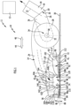
- a first embodiment of a floor nozzle device according to the invention which is shown schematically in the Figures 1 and 2 and designated there with 11, is intended for connection to a vacuum cleaner with a suction unit 12.
- the floor nozzle device 11 is designed here as a floor nozzle 10.
- the floor nozzle 10 is designed in particular for connection to a suction pipe or a suction hose of the vacuum cleaner.
- the floor nozzle 10 has a base body 14.
- a connection 16 is arranged on the base body 14, via which the floor nozzle 10 can be connected to the vacuum cleaner, in particular to establish a fluid-effective connection with the suction unit 12.
- connection 16 comprises a pipe socket 18 into which a pipe of the vacuum cleaner can be inserted.
- the pipe socket 18 at the connection 16 is rotatable about a rotation axis 22 via a joint 20.
- the base body 14 has a first part 24 and a second part 26. At least one support wheel 28 and in particular a pair of support wheels 28 are arranged on the base body 14, via which the floor nozzle 10 can be supported on a surface 30 to be cleaned. The at least one support wheel 28 can be arranged on the first part 24, the second part 26 or on both parts 24, 26.
- the support wheel(s) 28 are in particular rotatable about a rotation axis 32.
- the first part 24 is pivotably mounted on the second part 26 via a joint 34.
- the connection 16 is located on the second part 26.
- the second part 26 and the connection 16 preferably form a bend 19.
- the second part 26 forms in particular a first section of the Manifold 19.
- the connection 16 forms in particular a second section of the manifold 19.
- a corresponding pivot axis 36 is in particular parallel to the rotation axis 32.
- the joint 34 is arranged such that the pivot axis 36 coincides with the rotation axis 32 or is located near this rotation axis 32.
- Different holding heights can be compensated for via the joint 34; different holding heights correspond in particular to different angles at which a suction pipe arranged on the connection 16 is positioned in relation to the surface 30 to be cleaned.
- the joint 34 enables precisely such different holding heights.
- a suction head 38 is arranged on the base body 14.
- the suction head 38 supports the floor nozzle 10 at a distance from the support wheel(s) 28 and causes a suction flow to be applied to the surface 30 to be cleaned.
- the suction head 38 is arranged on the first part 24 of the base body 14. In one embodiment, the suction head 38 is mounted on the first part 24 of the base body 14 via a pivot joint 40.
- the pivot joint 40 defines a pivot axis 42 which is parallel to the rotation axis 32 or the pivot axis 36.
- a bottom side 39 of the suction head with respect to the direction of gravity comprises a sliding sole 41.
- the sliding sole 41 is made from a composite material.
- the composite material comprises at least one polymer as matrix material and fibers made from an electrically conductive material and/or platelets made from an electrically conductive material as filler.
- the composite material comprises at least one polymer and carbon-based fibers, for example carbon fibers as a filler.
- the composite comprises in particular carbon-based platelets, for example carbon platelets as a filler.
- the composite material is preferably an injection-moldable material.
- the composite material comprises the fibers made of an electrically conductive material and/or the platelets made of an electrically conductive material in a proportion of 10 to 20 wt.% based on the total mass of the composite material.
- the at least one polymer of the matrix material comprises one or more of the following polymers or is formed therefrom: polyamide (PA), in particular polyamide 6 (PA6) or polyamide 66 (PA66), polycarbonate (PC), acrylonitrile (AC), butadiene, styrene, in particular acrylonitrile-butadiene copolymer (ABS), polyolefin, in particular polypropylene (PP), polyketone, polymethyl methacrylate (PMMA), polyvinyl chloride (PVC).
- PA polyamide
- PA6 polyamide 6
- PA66 polycarbonate
- AC acrylonitrile
- ABS acrylonitrile-butadiene copolymer
- PP polypropylene
- PMMA polyketone
- PVC polyvinyl chloride
- polyamide 6 or polyamide 66 forms the matrix material.
- the fibers made of an electrically conductive material and/or platelets made of an electrically conductive material have an average length/average diameter of approximately 100 ⁇ m to approximately 3 mm.
- the composite material has a specific surface resistance of approximately 250 ⁇ to approximately 1 ⁇ 10 7 ⁇ .
- the filler has a specific resistance of 50 ⁇ mm 2 /m or less.
- carbon fibers with a resistance of 16 ⁇ mm 2 /m form the filler.
- manifold 19 is also made of the composite material described above.
- the suction head 38 is mounted on the base body 14 in the manner of a rocker. This enables an improved cleaning result, particularly in a textile surface cleaning function, in that a front suction edge (first suction edge 74, see below) can penetrate deeper into the textile material of the surface 30 to be cleaned when the floor nozzle 10 is pushed forward 44 above the surface 30 to be cleaned than a rear suction edge, and when the floor nozzle 10 is pushed backwards the rear suction edge (second suction edge 76, see below) can penetrate deeper into the textile material than the front suction edge.
- first suction edge 74 see below
- the forward thrust 44 preferably corresponds to a main movement direction of the floor nozzle 10.
- the first suction edge 74 and the second suction edge 76 are part of the sliding sole 41 and are made of the composite material according to the invention.
- a suction mouth 48 is arranged on the suction head 38.
- the suction mouth 48 comprises a first boundary wall 50 and a second boundary wall 52 opposite the first boundary wall (see also Figure 4 ).
- a ceiling wall 54 is positioned transversely to the first boundary wall 50 and the second boundary wall 52 and is connected to the first boundary wall 50 and the second boundary wall 52.
- the ceiling wall 54 closes the suction mouth 48 at the top, away from the surface 30 to be cleaned, when the floor nozzle 10 is moved over the Support wheels 28 and the suction head 38 are supported on the surface 30 to be cleaned.
- An opening 56 is formed in the top wall 54. At least one channel 58 is connected to this opening 56, which runs through the suction head 38 and the base body 14 to the connection 16.
- a suction chamber 60 is formed between the first boundary wall 50, the second boundary wall 52 and the top wall 54. The suction chamber 60 is fluidly connected to the suction unit 12 via the channel 58, so that a suction flow can act in the suction chamber 60 when a corresponding negative pressure is applied by the suction unit 12.
- the first boundary wall 50 has a first inner side 62a which delimits the suction chamber 60. It has a first outer side 62b which faces away from the first inner side 62a.
- the second boundary wall 52 has a second inner side 64a which delimits the suction chamber 60 and faces the first inner side 62a.
- the second boundary wall 52 also has a second outer side 64b which faces away from the second inner side 64a.
- the suction chamber 60 is laterally closed by opposite side walls 66, 68, which are connected to both the first boundary wall 50 and the second boundary wall 52.
- a suction opening 70 of the suction mouth 48 is formed between the first boundary wall 50, the second boundary wall 52 and the side walls 66, 68.
- the suction opening 70 opens the suction chamber 60 towards the surface 30 to be cleaned (when the floor nozzle 10 is operatively positioned on the surface 30 to be cleaned).
- the surface 30 to be cleaned can be subjected to a suction flow via the suction opening 70 and thus vacuumed.
- the suction mouth 48 forms a suction channel via the suction chamber 60 and the suction opening 70, which is open towards the surface 30 to be cleaned.
- the floor nozzle 10 is intended for vacuuming textile surfaces 72 as surfaces 30 to be cleaned.
- a textile surface 72 consists of textile material.
- the corresponding textile surface 72 is, for example, a carpet or a rug.
- a first suction edge 74 is formed on the front side of the first boundary wall 50 in the region of the suction opening 70.
- a second suction edge 76 is formed on the front side of the second boundary wall 52 in the region of the suction opening 70.
- the first suction edge 74 and the second suction edge 76 are formed, for example, by a correspondingly thin design of the first boundary wall 50 or the second boundary wall 52 on their respective front sides.
- first boundary wall 50 and the second boundary wall 52 are wedge-shaped at the front side in order to form the respective suction edge 74 and 76.
- the first boundary wall 50 is at a greater distance from the connection 16 or the support wheel 28 than the second boundary wall 52.
- the pivotable mounting of the suction head 38 on the base body 14 ensures that during a forward stroke 44 the first suction edge 74 penetrates deeper into the textile material than the second suction edge 76.
- the suction head 38 is designed and mounted such that during a backward stroke 46 the second suction edge 76 penetrates deeper into the textile material of the textile surface 72 than the first suction edge 74.
- the first suction edge 74 and the second suction edge 76 are designed such that in the textile surface cleaning function they are in an operative position and immerse themselves in the textile material of the textile surface 72 or This allows dust to be effectively extracted from the textile material of the textile surface 72.
- a wedge surface for the first suction edge 74 is oriented such that it lies between the first inner side 62a and the first outer side 62b and thereby recedes from the first inner side 62a to the first outer side 62b.
- a corresponding wedge surface on the second suction edge 76 is then in particular designed such that it lies between the second inner side 64a and the second outer side 64b and recedes towards the second outer side 64b.
- the suction head 38 has a first bottom wall 78 at the end opposite a surface 30 to be cleaned.
- This first bottom wall 78 is connected to the first boundary wall 50. It is directly connected to this and is oriented transversely to the first boundary wall 50.
- the first bottom wall 78 leads from the first boundary wall 50 in a direction to a front end 80 of the suction head 38.
- the suction head 38 also has a rear end 82 which faces away from the front end. The rear end 82 is closer to the support wheel 28 or to the connection 16 than the front end 80.
- the first bottom wall 78 has a first region 84 which is oriented at a (small) acute angle 86 to an envelope 88 to the first suction edge 74 and the second suction edge 76.
- the acute angle 86 is oriented such that the first bottom wall 78 in the first region 84 retreats in relation to the envelope 88 in the direction of the front end 80.
- a transition region 77 is arranged between the first suction edge 74 and the first region 84.
- a main extension plane of the transition region 77 preferably includes a at least approximately right angles with a main extension plane of the first boundary wall 50 and/or its first inner side 62a.
- the main extension plane of the transition region 77 encloses an obtuse angle with a main extension plane of the first region 84.
- the transition region 77 borders on the first region 84 in a blunt edge or in a rounded section.
- the transition region 77 has in particular a planar portion which is in particular aligned substantially parallel to the envelope 88.
- the suction head 38 has a second bottom wall 90.
- This second bottom wall 90 is connected to the second boundary wall 52 and adjoins it. It runs from the second boundary wall 52 (from the outside 64b) towards the rear end 82 of the suction head 38.
- the second bottom wall 90 has a second region 92 which is oriented at an acute angle 94 to the envelope 88.
- the second region 92 is designed such that, with respect to this envelope 88, it recedes from the second boundary wall 52 toward the rear end 82.
- the first region 84 and the second region 92 are designed as ramps due to their angular arrangement to the envelope 88.
- the acute angle 86 or 94 is in particular in the range between 5° and 15°.
- the first suction edge 74, the second suction edge 76, the first boundary wall 50, the second boundary wall 52, the first bottom wall 78 and/or the second bottom wall 90 are preferably components of the sliding sole 41.
- the first boundary wall 50 and the second boundary wall 52 can be arranged perpendicularly or at an angle to the envelope 88. They can be aligned parallel to one another or only partially parallel or not parallel to one another.
- the second region 92 is followed by a region 96 which is oriented, for example, parallel to the envelope 88.
- first bottom wall 78 in its first region 84 and/or the second bottom wall 90 in its second region 92 can come into contact with textile material of the textile surface 72. Usually, during normal use, no contact of the region 96 with the textile surface 72 is provided.
- a thread lifter 98a, 98b is arranged on the first region 84 of the first bottom wall 78 and on the second region 92 of the second bottom wall 90.
- an air flow 100, 100' (cf. Figure 1 ) flow through the textile material of the textile surface 72 past the first suction edge 74 or the second suction edge 76 into the suction chamber 60.
- the floor nozzle 10 is provided with (at least) one further flow path 102, 102', which is formed in the suction head 38 and via which air can be supplied to the outer side 62b of the first suction edge 74 or the second outer side 64b of the second suction edge 76 independently of the flow through the textile material of the textile surface 72.
- a first channel 104 is formed in the suction head 38, which is assigned to the first suction edge 74.
- This first channel 104 has an inlet 106, from which air from the surroundings of the floor nozzle 10 can be coupled into the corresponding flow path 102' (i.e. into the channel 104).
- the inlet 106 is formed by one or more openings formed between the first bottom wall 78 and a front wall 108 of the suction head 38.
- the front end 80 of the suction head 38 is located on the front wall 108.
- the corresponding inlet 106 for air is spaced from an upper side of the textile surface 72.
- a second channel 110 is formed for the flow path 102 in the suction head 38, which has (at least) one inlet 112, which is located, for example, between the region 96 of the second bottom wall 90 and a rear wall 114 of the suction head 38.
- the rear end 82 of the suction head 38 is located on the rear wall 114.
- the inlet 112 is spaced from an upper side of the textile surface 72 during proper operation.
- the inlet(s) 106 or 112 can also be arranged at another location on the suction head 38 or on the floor body 14 (with a corresponding channel connection to the suction head 38) in order to enable an air flow from the surroundings of the floor nozzle 10 through the suction head 38.
- the first bottom wall 78 forms a boundary of the first channel 104 with a corresponding inner side.
- the second bottom wall 90 forms a boundary of the second channel 110.
- the first channel 104 has an outlet 116, via which air flowing in the flow path 102' can be fed to the first suction edge 74 on the first outer side 62b of the first boundary wall 50.
- an additional air flow 118' to the air flow 100' is provided at the suction edge 74 via the flow path 102', which improves the suction result.
- the second channel 110 has an outlet 120, via which an additional air flow 118 can be provided on the second outer side 64b of the second suction edge 76.
- This additional air flow 118 is an additional air flow relative to the air flow 100 through the textile material. This improves the suction effect.
- the outlet 116 includes a plurality of openings 122 in the first bottom wall 78 in the immediate vicinity of the first suction edge 74.
- the openings 122 are slot-shaped and establish a flow-effective connection between the interior of the suction head 38 with the first channel 104 and an exterior space in the region of the first suction edge 74.
- the openings 122 are arranged in a row, wherein a longitudinal extension direction 124 of this row is in particular at least approximately parallel to the first suction edge 74.
- the outlet 120 is formed by openings 122', in particular spaced slot-shaped openings in a row are arranged with a longitudinal extension direction at least approximately parallel to the second suction edge 76 (cf. Figure 4 ).
- Both the first suction edge 74 and the second suction edge 76 are assigned a respective outlet 116 with openings 122 and 120 with openings 122', respectively.
- the openings 122, 122' have a width B in a spacing direction 126 between the first suction edge 74 and the second suction edge 76, which is in the range between 0.8 mm and 2.5 mm (cf. Figure 5 ).
- This size dimension applies equally to the openings 122 which are assigned to the first suction edge 74 and to the openings 122' which are assigned to the second suction edge 76.
- a distance D in the distance direction 126 between an opening 122 or 122' is in the range between 0.5 mm and 2.5 mm.
- the openings 122, 122' are thus located in the immediate vicinity of the corresponding first suction edge 74 or second suction edge 76.
- a single opening 122 or 122' has a length L in a transverse direction 128 to the spacing direction 126 which follows the corresponding suction edge 74 or 76.
- the openings 122, 122' have a length L on the order of approximately 15 mm.
- the total length of the outlet 116 or 120 as the sum of all lengths L is at least 30% and preferably at least 70% of the corresponding associated first suction edge 74 or 76.
- a suction edge 74 or 76 has a straight extension ( Figures 4 , 5 ).
- a first suction edge and/or a second suction edge 130 has a non-rectilinear design and, for example, has a central region 132, to which curved regions 134a, 134b adjoin on both sides.
- a corresponding outlet 136 with openings 138 follows the course of this suction edge (in the embodiment the second suction edge 130) including the curvature.
- a length of a corresponding opening 138 is then a length along a line which is parallel to a line of the corresponding second suction edge 130.
- a total length of the outlet 136 as the length of all openings 138 along the line of the second suction edge 130 is at least 30% and preferably at least 70% of the corresponding length of the second suction edge 130 along this line.
- a corresponding outlet 116, 120, 136 is formed by a single opening.
- the corresponding openings are formed, for example, by a plurality of round holes or even square holes.
- the slot-shaped openings 122, 122', 138 in the embodiments shown are rounded at their corners.
- a bypass air flow can be supplied to the corresponding suction edge 74, 76, which comes from the environment of the floor nozzle 10 and has at least partially flowed through the suction head 38.
- the negative pressure applied to the suction chamber 60 via the suction unit 12 drives this bypass air flow.
- outlets 116, 120, 136 are permanently present.
- an adjustment device 142 is provided, via which the air flow (bypass air flow) 118, 118' through the respective outlets 116, 120 can be varied.
- the adjustment device 142 comprises an adjustment element 144 assigned to the respective outlets 116, 120, which can act on the corresponding outlet 116, 120, 136 and via which an opening cross-section of the outlet 116, 120, 136 can be varied.
- the adjustment element 144 is designed such that there are the “closed outlet” positions 116 and 120 (with closed openings 122, 122') and the "open outlets” position.
- a slide 146 of the adjustment device 142 is guided in a lockable manner within the suction head 38 on an outside of the suction mouth 48 with the boundary walls 50, 52.
- the adjustment elements 144 are corresponding walls of the slide 146.
- the adjustment device 142 is controlled by a corresponding operating element 150, which is Figure 2 is displayed. A user can thereby set whether the additional air flow 118 or 118' is effective or not, i.e. whether the outlets 116, 120 are open.
- the adjustment device can also be provided if only a single suction edge 74 or 76 is assigned an outlet (cf. Figure 5 ).
- FIG. 3 The embodiment shown of a floor nozzle device 11' designed as a floor nozzle 10' has a variant of an adjustment device 152.
- the adjustment device 152 has adjustment elements 154 which are intended to be immersed in corresponding openings 122, 122'.
- the adjustment elements 144 are provided for covering the opening 122, 122', wherein in particular a cover is provided between the corresponding first boundary wall 50 and the first bottom wall 78 or the second boundary wall 52 and the second bottom wall 90 in an interior of the suction head 38.
- the adjustment elements 154 are designed such that, depending on their immersion depth in the corresponding opening 122, 122', a different opening area of the corresponding openings 122, 122', which results in a position between zero and, when not immersed, complete opening.
- the air flow 118, 118' which is then additionally present at the suction edges 74, 76, can be adjusted between "present” and “not present” (zero air flow).
- the additional air flow can be varied in intermediate ranges depending on the immersion depth of the adjustment element 154 in the associated openings 122, 122'.
- control element 150 An adjustment by an operator is possible via the control element 150.
- the adjustment device 142 or 152 enables adaptation to different types of textile material, such as carpet types. For example, an additional air flow 118, 118' is not necessary for highly air-permeable carpets. With closed outlets 116 or 120, better suction can be achieved with such a material.
- the floor nozzle 10 has a width b2 at the suction head 38 ( Figure 5 ).
- the suction opening 70 extends in the same direction over a width b1. It is provided that the width b1 corresponds at least approximately to the width b2 and preferably the width b1 is at least 90% and preferably at least 95% of the width b2.
- the floor nozzle 10 can be designed so that it only has a textile surface cleaning function.
- the first suction edge 74 and the second suction edge 76 are then constantly in an operative position.
- floor nozzle devices 11", 11′′′ designed as floor nozzles 10", 10′′′ each also have a hard surface cleaning function.
- a floor contact device 156 is arranged on the suction head (see, for example, Figure 2 , which is in a non-operative position in the textile surface cleaning function).
- the floor contact device 156 comprises, for example, brush lips 157 (or rubber lips) which are in an operative position in the hard surface cleaning function and which then rest on the surface 30 to be cleaned. (See Figures 7 and 8th ). With such a support, the first suction edge 74 and the second suction edge 76 are in a non-operative position. This is shown by the embodiments according to the Figures 7 and 8th explained in more detail.
- FIG 7 the floor nozzle device 11" designed as a floor nozzle 10" is shown, in which the floor contact device 156 is in an operative position and thus the floor nozzle 10" in a hard surface cleaning function In this position, a hard surface 158 can be vacuumed as the surface 30 to be cleaned via the floor nozzle 10".
- the floor support device 156 defines an enveloping surface 160, via which it stands on the hard surface 158. In a height direction, the first suction edge 74 and the second suction edge 76 are spaced from this enveloping surface 160, so that they are non-operative and do not touch the surface 30 to be cleaned.
- a switching device 162 is provided, via which it is possible to switch between the textile surface cleaning function and the hard surface cleaning function of the floor nozzle 10".
- the floor contact device 156 is in a non-operative position and is displaced into the suction head 38 in such a way that the surface 30 to be cleaned is not affected ( Figure 1 ).
- the first suction edge 74 and the second suction edge 76 are in an operative position and they can penetrate into the textile material of the surface 30 to be cleaned.
- the floor contact device 156 is positioned on the suction head 38 via the switching device 162 such that the envelope surface 160 lies beyond the first suction edge 74 and the second suction edge 76. As a result, the first suction edge 74 and the second suction edge 76 are in a non-operative position and the floor contact device 156 is in the operative position.
- the floor installation device 156 in the hard surface cleaning function ensures a flow-effective (approximate) sealing of a space 164 between the floor installation device 156 and the hard surface 158, wherein the suction mouth 48 with the suction opening 70 is positioned in this space.
- the switching device 162 is coupled to an adjustment device 166 for the additional air flows 118, 118'.
- the adjustment device 166 has adjustment elements 168 which are coupled to the switching device 162 and serve to close the outlets 116, 120 with the openings 122, 122'.
- the adjustment elements 168 are positioned such that they release the outlets 116, 120 and thus the additional air flows 118, 118' can be applied to the first suction edge 74 and the second suction edge 76 on the respective outside of the access and boundary walls.
- the adjustment elements 168 are positioned so that they close the outlets 116, 120 ( Figure 8 ). This means that no false air can be drawn in via the outlets 116, 120 during the hard surface cleaning function.
- the adjustment elements 168 are designed as sliders or are arranged on a slider 170 which is slidably guided in the suction head 38.
- a displacement movement and positioning of the slider 170 is effected via the switching device 162 in such a way that, as described, in the operative position of the floor support device 156, the outlets 116, 120 are closed and in the operative position of the suction edges 74, 76 (in a non-operative position of the floor support device 156) the outlets 116, 120 are open.
- the floor nozzle 10 for the textile surface cleaning function has an additional flow path 102, 102' for each of its suction edges 74, 76 or only one suction edge 74 or 76, via which air from the environment can be made available on an outside of the suction mouth 48 of the respective suction edge 74, 76.
- the floor nozzle sucks less onto the textile material and the pushing force required to move the floor nozzle on the textile material is reduced.
- an outlet 116 or 120 can be closed or its cross-section can be adjusted to enable adaptation to textile material.
- one or more openings 122, 122' are arranged close to the corresponding suction edge 74 or 76 on a corresponding bottom wall 78 or 90, which in turn are assigned to the respective outer side 62b, 64b of the corresponding boundary wall 50, 52 on which the suction edge 74 or 76 is formed.
- the ambient air which then flows in via the corresponding additional air flow 118, 118', is less throttled than the air flows 100, 100', which flow through the textile material to the suction opening 70.
- the suction air in the additional air streams 118, 118' has a shorter path through the textile material and is throttled less. This results in a large volume flow at the corresponding suction edge 74, 76.
- the floor nozzle 10 When operating the floor nozzle 10, it is connected to a suction unit 12. In particular, an operator moves the floor nozzle 10 over the surface 30 to be cleaned via a suction pipe.
- FIG. 9 A further embodiment of a floor nozzle device 111 according to the invention is shown in Figure 9 shown schematically.
- the floor nozzle device 111 is designed as a floor nozzle 101 according to this embodiment.
- the floor nozzle device 111 according to the embodiment of the Figure 9 differs essentially from the embodiments of the Figures 1 to 3 that there are no bypass channels and no ambient air flows in as an additional air flow 118, 118'.
- the floor nozzle 101 does not comprise an adjustment device 142.
- an air flow 174, 174' flows from edge regions of the essentially trough-shaped suction head 176 through the textile material of the textile surface 178 past the first suction edge 180 or the second suction edge 182 into the suction chamber 172.
- the first suction edge 180 and the second suction edge 182 each form a component of the sliding sole 177.
- the first boundary wall 179 and the second boundary wall 181 preferably form components of the sliding sole 177.
- FIG. 10 Another in Figure 10 The embodiment shown in Fig. 1 of a floor nozzle device 111' designed as a floor nozzle 101' differs essentially from the one shown in Figure 9 illustrated embodiment that a ground support device 184 is shown in an operative position.
- the first suction edge 194 and the second suction edge 196 are spaced from the surface 30 to be cleaned in the hard surface cleaning function.
- a space 200 is created between an underside 198 of the sliding sole 202, the suction space 204 and the surface 30 to be cleaned, which is sealed by the brush lips 186, 186'.
- the floor nozzle device 111 preferably has a suction channel 175 with a substantially rectangular cross-section.
- the cross-section is taken along a plane which runs parallel to the textile surface 178.
- the suction channel 175 is preferably designed to be closed at the sides.
- the suction channel 175 has in particular a curved shape.
- the width of a cross section decreases towards the lateral edges of the floor nozzle 101.
- the cross section is taken perpendicular to an envelope surface of the textile surface 178, which runs through the center of the suction channel 175.
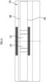
- FIG. 13 The embodiment shown of a floor nozzle device 111" designed as a floor nozzle 101" differs from that shown in Figure 9 illustrated embodiment of a floor nozzle device 111 essentially in that the sliding sole 206 does not extend over the entire underside 207 of the suction head 208.
- the sliding sole 206 made from the composite material is in this case formed in two parts and is arranged in the area of the first suction edge 210 and in the area of the second suction edge 212, respectively.
- the sliding sole 206 extends essentially over the areas that are in material contact with the textile material of the surface 30 to be cleaned in the textile surface cleaning function. In this way, charging effects can be reduced and the mechanical rigidity optimized, but a large part of the floor nozzle device 111" can be made from a plastic material other than the composite material.
- a plastic material without filler or a plastic material with fillers other than the composite material can be used for areas other than the sliding sole 206.
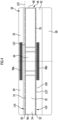
- FIG 14 an embodiment of a cleaning roller 220 according to the invention is shown schematically.
- the cleaning roller 220 is particularly suitable for use in a floor nozzle device according to the invention or a suction machine according to the invention.
- the cleaning roller 220 can be mounted and used in a sweeper or a self-propelled and self-steering vacuum robot.
- the cleaning roller 220 preferably has an at least approximately cylindrical base body 222.
- the cleaning roller 220 further comprises in particular a shaft 224, which is arranged on opposite end faces of the base body 222 and serves for rotatable attachment to a cleaning roller holder (not shown).
- the shaft 224 is arranged parallel to a longitudinal central axis 226.
- the longitudinal central axis 226 is parallel to an axis of rotation about which the cleaning roller 220 is rotatably mounted.
- a bristle holder 230 for receiving a plurality of bristles 232 is arranged on a lateral surface 228 of the base body 222.
- the bristles 232 are in particular essentially cylindrical, for example circular-cylindrical. Individual bristles 232 preferably have a diameter perpendicular to their main extension direction of approximately 0.3 mm to 2.0 mm, preferably 0.5 mm to 1.5 mm.
- the base body 222 forms the bristle receptacle 230.
- the bristle receptacle 230 comprises openings 234, in particular parallel rows of openings 234 in projections 236, which are arranged on the lateral surface 228 of the base body 222.
- the projections 236 are preferably rib-shaped and extend parallel to the longitudinal center axis 226 along the lateral surface 228. Bristles 232 are accommodated in the openings 234 and are arranged in bundles 235.
- the bundles 235 preferably have a diameter of approximately 5 mm or more.
- the bristles 232 extend in bundles 235 radially away from the longitudinal central axis 226.
- the bundles 235 are in particular arranged in rows which are arranged parallel to each other.
- the dust In an assembled state of the cleaning roller 220, the dust is whirled up by means of the bristles 232 during the rotating operation of the cleaning roller 220 and is thrown into an adjacent suction chamber in which the dust is sucked away.
- the bristles 232 have a length of approximately 5 cm or more, in particular approximately 15 cm or less.
- the total diameter of the cleaning roller 220 is preferably about 10 cm or more to about 40 cm, preferably about 25 cm or more.
- the total diameter of the cleaning roller 220 is approximately 40 cm or less, in particular approximately 35 cm or less.
- the bristles 232 are preferably arranged in bundles 235 which extend radially away from the longitudinal central axis 226.
- the bundles 235 preferably form rows of bundles 235 which are arranged parallel to the longitudinal central axis 226 in the projections 236 of the bristle receptacle 230.
- a series includes 50 to 60 bundles 235.
- bristles 232 or bundles 235 of bristles 232 are arranged helically or in a V-shape around the base body 222.
- the bristles 232 are made of a composite material comprising a polymer and carbon-based fibers and/or carbon-based platelets as filler.
- Polyamide in particular polyamide 6 or polyamide 66, is preferably suitable as the matrix material.
- the composite material contains carbon fibers in a proportion of approximately 13 wt.% based on the total mass of the composite material.
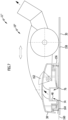
- FIG 15 shows an embodiment of a suction machine 242 designed as a self-steering and self-propelled vacuum robot 240 from below.
- the vacuum robot 240 comprises a floor nozzle device 244.
- the vacuum robot 240 forms a suction head 246, which has an at least approximately spherical segment-shaped area which, during operation of the vacuum robot 240, forms an upper side facing away from the surface 30 to be cleaned.
- the at least approximately spherical segment-shaped region of the suction head 246 is, for example, flattened and/or is closed at its edges by a bottom side 241 facing the surface 30 to be cleaned.
- the bottom side 241 is arranged below the suction head 246 with respect to the direction of gravity and is essentially planar.
- areas of the underside 241 are preferably in direct material contact with the surface 30 to be cleaned. Additionally or alternatively, areas of the underside 241 during operation of the vacuum robot 240 are in particular a small distance from the surface to be cleaned, such that an air flow can be generated between the underside 241 and the surface 30 to be cleaned, by means of which dust and the like can be vacuumed away.
- the underside 241 preferably comprises a sliding sole 248, which in one embodiment forms the underside 241.
- the sliding sole 248 partially forms the underside 241 and other areas have other properties.
- the sliding sole 248 is made of a composite material.
- the composite material comprises at least one polymer as matrix material and carbon-based fibers, in particular carbon fibers, and/or carbon-based platelets, in particular carbon platelets, as filler.
- the sliding sole 248 comprises polyamide 6 as matrix material, in which approximately 10 wt.% to approximately 12 wt.% carbon fibers are dispersed.
- the carbon fibers in the raw state preferably have a length of approximately 1 to approximately 4 mm.
- the sliding sole 248 is manufactured in an injection molding process.
- all areas of the underside 241 which are in direct contact with the surface 30 to be cleaned during operation of the vacuum robot 240 are formed by the sliding sole 248 made of the composite material according to the invention.
- the sliding sole 248 comprises an opening 250 which forms a suction mouth 252. Dust can be sucked out via the suction mouth 252 by applying negative pressure.
- the composite material has one or more of the features and advantages explained above.
- the suction mouth 252 is essentially rectangular in a cross section taken parallel to the underside 241.
- the suction mouth 252 has a main extension direction which is aligned essentially perpendicular to a main movement direction 254 of the vacuum robot 240.
- a cleaning roller 256 according to the invention is arranged in an edge region of the suction mouth 252, the bristle holder and/or bristles of which are made from the composite material according to the invention.
- a longitudinal center axis of the cleaning roller 256 is arranged essentially perpendicular to the main movement direction 254 of the vacuum robot 240.
- the bristles of the cleaning roller 256 are arranged in bundles which are arranged spirally around the longitudinal center axis of the cleaning roller 256.
- the suction mouth 252 is preferably as shown in the drawings in connection with the Figures 1 to 13 described embodiments.
- the vacuum robot 240 comprises on its underside 241, for example in an equatorial region of the underside 241, a wheel 258, preferably two wheels 258, 258', for moving the vacuum robot 240 on the surface 30 to be cleaned.
- the wheels 258, 258' are mounted so as to be rotatable about axes of rotation which are arranged perpendicular to the main direction of movement 254 of the vacuum robot 240.
- the axes of rotation of the wheels 258, 258' form an obtuse angle with one another and/or that the axes of rotation at the intersection point of the axes of rotation of the two wheels 258, 258' each form an acute angle with the main direction of movement 254 of the vacuum robot 240.
- the vacuum robot 240 can be moved over the surface 30 to be cleaned.
- the vacuum robot 240 comprises a control device 260 for controlling the movement and suction power of the vacuum robot 240.
- the control device 260 preferably comprises one or more sensor devices.
- Figure 16 shows a diagram in which measurement results are documented.
- the charge V in volts [V] of test rods made of different materials was measured.
- Test rod ends with a sprayed smooth surface and a width of approximately 20 mm, a thickness of approximately 4 mm and a length of approximately 35 mm were used.
- the test rods were pressed onto a test carpet in accordance with EN 60312 with a force of 30 N and moved at an average speed of 0.3 m/s with 10 double strokes over a sliding length of approximately 20 cm.
- test rods examined show comparable results of around 15 N.
- the minimally lower force F 1 to be applied for test rods made of PC/ABS and PMMA in comparison to test rods made of the composite material PA6CF15 according to the invention is not meaningful in isolation, since the high electrostatic charge results in relatively poor dust absorption and the suction power for comparable dust absorption must be increased to such an extent that the pushing force to be applied is significantly increased (cf. Figure 17 ).
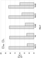
- Figure 17 shows a diagram in which measurement results of investigations into the pushing force F 2 to be applied for floor nozzles made of different materials are presented.
- the pushing force required by a floor nozzle was measured depending on the materials with a previously set comparable dust absorption dpu C in % (over 80 %) in accordance with the EN 60312 standard.
- the floor nozzle made of the inventive composite material PA6CF15 shows the best sliding behavior of the materials examined.
- the floor nozzle made of the composite material according to the invention has the best sliding behavior.
Landscapes
- Engineering & Computer Science (AREA)
- Mechanical Engineering (AREA)
- Nozzles For Electric Vacuum Cleaners (AREA)
Priority Applications (1)
| Application Number | Priority Date | Filing Date | Title |
|---|---|---|---|
| PL17727889.2T PL3634193T3 (pl) | 2017-06-06 | 2017-06-06 | Urządzenie z dyszą podłogową, wałek czyszczący do czyszczenia powierzchni tekstylnych i maszyna ssąca |
Applications Claiming Priority (1)
| Application Number | Priority Date | Filing Date | Title |
|---|---|---|---|
| PCT/EP2017/063649 WO2018224127A1 (de) | 2017-06-06 | 2017-06-06 | Bodendüsenvorrichtung, reinigungswalze für eine textilflächen-reinigung und saugmaschine |
Publications (3)
| Publication Number | Publication Date |
|---|---|
| EP3634193A1 EP3634193A1 (de) | 2020-04-15 |
| EP3634193B1 true EP3634193B1 (de) | 2024-07-17 |
| EP3634193C0 EP3634193C0 (de) | 2024-07-17 |
Family
ID=59009698
Family Applications (1)
| Application Number | Title | Priority Date | Filing Date |
|---|---|---|---|
| EP17727889.2A Active EP3634193B1 (de) | 2017-06-06 | 2017-06-06 | Bodendüsenvorrichtung, reinigungswalze für eine textilflächen-reinigung und saugmaschine |
Country Status (4)
| Country | Link |
|---|---|
| EP (1) | EP3634193B1 (pl) |
| CN (1) | CN110708993B (pl) |
| PL (1) | PL3634193T3 (pl) |
| WO (1) | WO2018224127A1 (pl) |
Families Citing this family (1)
| Publication number | Priority date | Publication date | Assignee | Title |
|---|---|---|---|---|
| EP4311463A1 (en) * | 2022-07-26 | 2024-01-31 | Nilfisk A/S | Suction nozzle and vacuum cleaner comprising a suction nozzle |
Family Cites Families (24)
| Publication number | Priority date | Publication date | Assignee | Title |
|---|---|---|---|---|
| DE19547311A1 (de) * | 1995-12-18 | 1997-06-19 | Wessel Werk Gmbh | Staubsaugerdüse |
| JPH11346967A (ja) | 1998-06-09 | 1999-12-21 | Ikemoto Brush Kogyo Kk | 電気掃除機用吸込具 |
| DE19846103A1 (de) | 1998-10-07 | 2000-04-20 | Vorwerk Co Interholding | Staubsauger |
| JP2002136457A (ja) * | 2000-10-31 | 2002-05-14 | Matsushita Electric Ind Co Ltd | 排気循環式掃除機 |
| US6574830B2 (en) | 2001-07-23 | 2003-06-10 | Michael D Huddleston | Vacuum operated cleaning accessory with roller brush |
| AU2003273643A1 (en) | 2003-10-14 | 2005-04-27 | Lange Christian S.A. | Suction nozzle |
| US7299518B1 (en) * | 2003-11-20 | 2007-11-27 | Paulson Jerome I | Vacuum cleaner with magnetic flux field |
| DE102005055614A1 (de) | 2005-11-22 | 2007-05-24 | Andreas Stihl Ag & Co. Kg | Arbeitsgerät |
| DE102007009958B4 (de) | 2007-03-01 | 2013-08-01 | Wessel-Werk Gmbh | Blechgleitsohle sowie Verfahren zu deren Auslegung |
| CN201094596Y (zh) * | 2007-07-17 | 2008-08-06 | 无锡市宏富电器制造有限公司 | 抗静电轮滑地面刷 |
| GB2470919A (en) | 2009-06-09 | 2010-12-15 | Dyson Technology Ltd | Agitating means for a cleaning head |
| GB2470917A (en) | 2009-06-09 | 2010-12-15 | Dyson Technology Ltd | Agitating means for cleaning head |
| CN101953661A (zh) * | 2009-07-20 | 2011-01-26 | 乐金电子(天津)电器有限公司 | 吸尘器的集尘盒 |
| EP2343003A1 (en) * | 2010-01-07 | 2011-07-13 | Koninklijke Philips Electronics N.V. | Cleaning device with spraying means and rotatable brush |
| GB2476810B (en) | 2010-01-08 | 2014-01-08 | Dyson Technology Ltd | Cleaner head for a vacuum cleaner |
| US8745818B2 (en) * | 2010-01-08 | 2014-06-10 | Dyson Technology Limited | Cleaner head |
| GB2487920B (en) * | 2011-02-08 | 2013-01-09 | Dyson Technology Ltd | A cleaner head |
| JP5265722B2 (ja) | 2011-03-15 | 2013-08-14 | 日立アプライアンス株式会社 | 電気掃除機 |
| JP5950270B2 (ja) * | 2011-04-18 | 2016-07-13 | 日立アプライアンス株式会社 | 吸込具 |
| JP2012249699A (ja) | 2011-05-31 | 2012-12-20 | Hitachi Appliances Inc | 電気掃除機 |
| GB2499542B (en) | 2011-06-22 | 2014-01-15 | Dyson Technology Ltd | A surface treating appliance |
| GB2492117A (en) | 2011-06-22 | 2012-12-26 | Dyson Technology Ltd | Agitating apparatus for a surface treating appliance |
| JP5929718B2 (ja) * | 2012-11-09 | 2016-06-08 | 三菱電機株式会社 | 掃除具及びこれを備えた電気掃除機 |
| JP6439151B2 (ja) * | 2014-08-07 | 2018-12-19 | パナソニックIpマネジメント株式会社 | 樹脂構造体およびこれを用いた電気掃除機 |
-
2017
- 2017-06-06 EP EP17727889.2A patent/EP3634193B1/de active Active
- 2017-06-06 WO PCT/EP2017/063649 patent/WO2018224127A1/de not_active Ceased
- 2017-06-06 CN CN201780091645.2A patent/CN110708993B/zh active Active
- 2017-06-06 PL PL17727889.2T patent/PL3634193T3/pl unknown
Also Published As
| Publication number | Publication date |
|---|---|
| EP3634193A1 (de) | 2020-04-15 |
| PL3634193T3 (pl) | 2024-12-16 |
| CN110708993A (zh) | 2020-01-17 |
| CN110708993B (zh) | 2025-06-17 |
| EP3634193C0 (de) | 2024-07-17 |
| WO2018224127A1 (de) | 2018-12-13 |
Similar Documents
| Publication | Publication Date | Title |
|---|---|---|
| DE60126965T2 (de) | Bodenwerkzeug | |
| DE3874444T2 (de) | Reinigungskopf. | |
| DE4314046C2 (de) | Verfahren und Vorrichtung zum Entfernen von an Oberflächen anhaftenden Partikeln durch ein Wischelement | |
| EP0265466B1 (de) | Florfaserbürste zur reinigung von textilgeweben | |
| EP3206548A1 (de) | Flächen-reinigungsmaschine und verfahren zum betreiben einer flächen-reinigungsmaschine | |
| WO2011120502A2 (de) | Verfahren zum reinigen von oberflächen, insbesondere glasscheiben | |
| EP0552652A1 (de) | Bodendüse für Staubsauger | |
| DE1760812B2 (de) | Verfahren und Vorrichtung zur Herstellung eines Vliesgefüges von bestimmter Fadenrichtungseigenschaft | |
| DE102015103500A1 (de) | Reinigungsgerät | |
| DE102018105461A1 (de) | Reinigungsgerät | |
| EP3634193B1 (de) | Bodendüsenvorrichtung, reinigungswalze für eine textilflächen-reinigung und saugmaschine | |
| DE102014111702B4 (de) | Elektroteppichbürste zum Reinigen eines Untergrunds | |
| DE102010052010A1 (de) | Vorrichtung zum Trockenformen einer Faserbahn | |
| DE102007014506A1 (de) | Verfahrbares Haushalts-Bodenfeuchtreinigungsgerät | |
| EP2939581B1 (de) | Selbstfahrendes reinigungsgerät und betriebsverfahren für ein selbstfahrendes reinigungsgerät | |
| EP3586709B1 (de) | Bodendüse für staubsauger und staubsauger | |
| EP3500145B1 (de) | Bodendüse für einen staubsauger, verfahren zum absaugen von textilflächen und staubsauger | |
| DE29918620U1 (de) | Reinigungstextilie | |
| EP3424396B1 (de) | Reinigungstuch für eine reinigungseinrichtung | |
| DE102017100608B4 (de) | Bodenplatte für eine Saugdüse mit Luftleitelementen | |
| DE4112394A1 (de) | Aufsteckvorrichtung fuer einen staubsauger | |
| DE202011000185U1 (de) | Saugdüse | |
| EP2534991B1 (de) | Bodendüse für einen Staubsauger und Staubsauger mit einer solchen Bodendüse | |
| EP3808241B1 (de) | Saugroboter zur autonomen reinigung von bodenflächen eines raums | |
| DE3420698A1 (de) | Saugmundstueck |
Legal Events
| Date | Code | Title | Description |
|---|---|---|---|
| STAA | Information on the status of an ep patent application or granted ep patent |
Free format text: STATUS: UNKNOWN |
|
| STAA | Information on the status of an ep patent application or granted ep patent |
Free format text: STATUS: THE INTERNATIONAL PUBLICATION HAS BEEN MADE |
|
| PUAI | Public reference made under article 153(3) epc to a published international application that has entered the european phase |
Free format text: ORIGINAL CODE: 0009012 |
|
| STAA | Information on the status of an ep patent application or granted ep patent |
Free format text: STATUS: REQUEST FOR EXAMINATION WAS MADE |
|
| 17P | Request for examination filed |
Effective date: 20191203 |
|
| AK | Designated contracting states |
Kind code of ref document: A1 Designated state(s): AL AT BE BG CH CY CZ DE DK EE ES FI FR GB GR HR HU IE IS IT LI LT LU LV MC MK MT NL NO PL PT RO RS SE SI SK SM TR |
|
| AX | Request for extension of the european patent |
Extension state: BA ME |
|
| DAV | Request for validation of the european patent (deleted) | ||
| DAX | Request for extension of the european patent (deleted) | ||
| STAA | Information on the status of an ep patent application or granted ep patent |
Free format text: STATUS: EXAMINATION IS IN PROGRESS |
|
| 17Q | First examination report despatched |
Effective date: 20220408 |
|
| P01 | Opt-out of the competence of the unified patent court (upc) registered |
Effective date: 20230523 |
|
| GRAP | Despatch of communication of intention to grant a patent |
Free format text: ORIGINAL CODE: EPIDOSNIGR1 |
|
| STAA | Information on the status of an ep patent application or granted ep patent |
Free format text: STATUS: GRANT OF PATENT IS INTENDED |
|
| INTG | Intention to grant announced |
Effective date: 20240214 |
|
| GRAS | Grant fee paid |
Free format text: ORIGINAL CODE: EPIDOSNIGR3 |
|
| GRAA | (expected) grant |
Free format text: ORIGINAL CODE: 0009210 |
|
| STAA | Information on the status of an ep patent application or granted ep patent |
Free format text: STATUS: THE PATENT HAS BEEN GRANTED |
|
| AK | Designated contracting states |
Kind code of ref document: B1 Designated state(s): AL AT BE BG CH CY CZ DE DK EE ES FI FR GB GR HR HU IE IS IT LI LT LU LV MC MK MT NL NO PL PT RO RS SE SI SK SM TR |
|
| REG | Reference to a national code |
Ref country code: CH Ref legal event code: EP |
|
| REG | Reference to a national code |
Ref country code: DE Ref legal event code: R096 Ref document number: 502017016262 Country of ref document: DE |
|
| REG | Reference to a national code |
Ref country code: IE Ref legal event code: FG4D Free format text: LANGUAGE OF EP DOCUMENT: GERMAN |
|
| U01 | Request for unitary effect filed |
Effective date: 20240812 |
|
| P04 | Withdrawal of opt-out of the competence of the unified patent court (upc) registered |
Free format text: CASE NUMBER: APP_48688/2024 Effective date: 20240826 |
|
| U07 | Unitary effect registered |
Designated state(s): AT BE BG DE DK EE FI FR IT LT LU LV MT NL PT RO SE SI Effective date: 20240902 |
|
| P05 | Withdrawal of opt-out of the competence of the unified patent court (upc) changed |
Free format text: CASE NUMBER: APP_48688/2024 Effective date: 20240902 |
|
| PG25 | Lapsed in a contracting state [announced via postgrant information from national office to epo] |
Ref country code: NO Free format text: LAPSE BECAUSE OF FAILURE TO SUBMIT A TRANSLATION OF THE DESCRIPTION OR TO PAY THE FEE WITHIN THE PRESCRIBED TIME-LIMIT Effective date: 20241017 |
|
| PG25 | Lapsed in a contracting state [announced via postgrant information from national office to epo] |
Ref country code: GR Free format text: LAPSE BECAUSE OF FAILURE TO SUBMIT A TRANSLATION OF THE DESCRIPTION OR TO PAY THE FEE WITHIN THE PRESCRIBED TIME-LIMIT Effective date: 20241018 |
|
| PG25 | Lapsed in a contracting state [announced via postgrant information from national office to epo] |
Ref country code: IS Free format text: LAPSE BECAUSE OF FAILURE TO SUBMIT A TRANSLATION OF THE DESCRIPTION OR TO PAY THE FEE WITHIN THE PRESCRIBED TIME-LIMIT Effective date: 20241117 |
|
| PG25 | Lapsed in a contracting state [announced via postgrant information from national office to epo] |
Ref country code: HR Free format text: LAPSE BECAUSE OF FAILURE TO SUBMIT A TRANSLATION OF THE DESCRIPTION OR TO PAY THE FEE WITHIN THE PRESCRIBED TIME-LIMIT Effective date: 20240717 |
|
| PG25 | Lapsed in a contracting state [announced via postgrant information from national office to epo] |
Ref country code: ES Free format text: LAPSE BECAUSE OF FAILURE TO SUBMIT A TRANSLATION OF THE DESCRIPTION OR TO PAY THE FEE WITHIN THE PRESCRIBED TIME-LIMIT Effective date: 20240717 Ref country code: RS Free format text: LAPSE BECAUSE OF FAILURE TO SUBMIT A TRANSLATION OF THE DESCRIPTION OR TO PAY THE FEE WITHIN THE PRESCRIBED TIME-LIMIT Effective date: 20241017 |
|
| PG25 | Lapsed in a contracting state [announced via postgrant information from national office to epo] |
Ref country code: RS Free format text: LAPSE BECAUSE OF FAILURE TO SUBMIT A TRANSLATION OF THE DESCRIPTION OR TO PAY THE FEE WITHIN THE PRESCRIBED TIME-LIMIT Effective date: 20241017 Ref country code: NO Free format text: LAPSE BECAUSE OF FAILURE TO SUBMIT A TRANSLATION OF THE DESCRIPTION OR TO PAY THE FEE WITHIN THE PRESCRIBED TIME-LIMIT Effective date: 20241017 Ref country code: IS Free format text: LAPSE BECAUSE OF FAILURE TO SUBMIT A TRANSLATION OF THE DESCRIPTION OR TO PAY THE FEE WITHIN THE PRESCRIBED TIME-LIMIT Effective date: 20241117 Ref country code: HR Free format text: LAPSE BECAUSE OF FAILURE TO SUBMIT A TRANSLATION OF THE DESCRIPTION OR TO PAY THE FEE WITHIN THE PRESCRIBED TIME-LIMIT Effective date: 20240717 Ref country code: GR Free format text: LAPSE BECAUSE OF FAILURE TO SUBMIT A TRANSLATION OF THE DESCRIPTION OR TO PAY THE FEE WITHIN THE PRESCRIBED TIME-LIMIT Effective date: 20241018 Ref country code: ES Free format text: LAPSE BECAUSE OF FAILURE TO SUBMIT A TRANSLATION OF THE DESCRIPTION OR TO PAY THE FEE WITHIN THE PRESCRIBED TIME-LIMIT Effective date: 20240717 |
|
| PG25 | Lapsed in a contracting state [announced via postgrant information from national office to epo] |
Ref country code: SM Free format text: LAPSE BECAUSE OF FAILURE TO SUBMIT A TRANSLATION OF THE DESCRIPTION OR TO PAY THE FEE WITHIN THE PRESCRIBED TIME-LIMIT Effective date: 20240717 |
|
| PG25 | Lapsed in a contracting state [announced via postgrant information from national office to epo] |
Ref country code: CZ Free format text: LAPSE BECAUSE OF FAILURE TO SUBMIT A TRANSLATION OF THE DESCRIPTION OR TO PAY THE FEE WITHIN THE PRESCRIBED TIME-LIMIT Effective date: 20240717 |
|
| PG25 | Lapsed in a contracting state [announced via postgrant information from national office to epo] |
Ref country code: SK Free format text: LAPSE BECAUSE OF FAILURE TO SUBMIT A TRANSLATION OF THE DESCRIPTION OR TO PAY THE FEE WITHIN THE PRESCRIBED TIME-LIMIT Effective date: 20240717 |
|
| PLBE | No opposition filed within time limit |
Free format text: ORIGINAL CODE: 0009261 |
|
| STAA | Information on the status of an ep patent application or granted ep patent |
Free format text: STATUS: NO OPPOSITION FILED WITHIN TIME LIMIT |
|
| 26N | No opposition filed |
Effective date: 20250422 |
|
| PGFP | Annual fee paid to national office [announced via postgrant information from national office to epo] |
Ref country code: PL Payment date: 20250428 Year of fee payment: 9 |
|
| PGFP | Annual fee paid to national office [announced via postgrant information from national office to epo] |
Ref country code: GB Payment date: 20250425 Year of fee payment: 9 |
|
| U20 | Renewal fee for the european patent with unitary effect paid |
Year of fee payment: 9 Effective date: 20250624 |
|
| REG | Reference to a national code |
Ref country code: CH Ref legal event code: H13 Free format text: ST27 STATUS EVENT CODE: U-0-0-H10-H13 (AS PROVIDED BY THE NATIONAL OFFICE) Effective date: 20260127 |
|
| PG25 | Lapsed in a contracting state [announced via postgrant information from national office to epo] |
Ref country code: MC Free format text: LAPSE BECAUSE OF FAILURE TO SUBMIT A TRANSLATION OF THE DESCRIPTION OR TO PAY THE FEE WITHIN THE PRESCRIBED TIME-LIMIT Effective date: 20240717 |
|
| PG25 | Lapsed in a contracting state [announced via postgrant information from national office to epo] |
Ref country code: IE Free format text: LAPSE BECAUSE OF NON-PAYMENT OF DUE FEES Effective date: 20250606 |