EP3634895B1 - Trommeln zum transportieren und zuführen von draht - Google Patents
Trommeln zum transportieren und zuführen von draht Download PDFInfo
- Publication number
- EP3634895B1 EP3634895B1 EP18734676.2A EP18734676A EP3634895B1 EP 3634895 B1 EP3634895 B1 EP 3634895B1 EP 18734676 A EP18734676 A EP 18734676A EP 3634895 B1 EP3634895 B1 EP 3634895B1
- Authority
- EP
- European Patent Office
- Prior art keywords
- drum
- wire
- access door
- end surface
- hold
- Prior art date
- Legal status (The legal status is an assumption and is not a legal conclusion. Google has not performed a legal analysis and makes no representation as to the accuracy of the status listed.)
- Active
Links
Images


Classifications
-
- B—PERFORMING OPERATIONS; TRANSPORTING
- B65—CONVEYING; PACKING; STORING; HANDLING THIN OR FILAMENTARY MATERIAL
- B65D—CONTAINERS FOR STORAGE OR TRANSPORT OF ARTICLES OR MATERIALS, e.g. BAGS, BARRELS, BOTTLES, BOXES, CANS, CARTONS, CRATES, DRUMS, JARS, TANKS, HOPPERS, FORWARDING CONTAINERS; ACCESSORIES, CLOSURES, OR FITTINGS THEREFOR; PACKAGING ELEMENTS; PACKAGES
- B65D85/00—Containers, packaging elements or packages, specially adapted for particular articles or materials
- B65D85/02—Containers, packaging elements or packages, specially adapted for particular articles or materials for annular articles
- B65D85/04—Containers, packaging elements or packages, specially adapted for particular articles or materials for annular articles for coils of wire, rope or hose
-
- B—PERFORMING OPERATIONS; TRANSPORTING
- B65—CONVEYING; PACKING; STORING; HANDLING THIN OR FILAMENTARY MATERIAL
- B65H—HANDLING THIN OR FILAMENTARY MATERIAL, e.g. SHEETS, WEBS, CABLES
- B65H49/00—Unwinding or paying-out filamentary material; Supporting, storing or transporting packages from which filamentary material is to be withdrawn or paid-out
- B65H49/02—Methods or apparatus in which packages do not rotate
- B65H49/04—Package-supporting devices
- B65H49/06—Package-supporting devices for a single operative package
- B65H49/08—Package-supporting devices for a single operative package enclosing the package
-
- B—PERFORMING OPERATIONS; TRANSPORTING
- B23—MACHINE TOOLS; METAL-WORKING NOT OTHERWISE PROVIDED FOR
- B23K—SOLDERING OR UNSOLDERING; WELDING; CLADDING OR PLATING BY SOLDERING OR WELDING; CUTTING BY APPLYING HEAT LOCALLY, e.g. FLAME CUTTING; WORKING BY LASER BEAM
- B23K9/00—Arc welding or cutting
- B23K9/12—Automatic feeding or moving of electrodes or work for spot or seam welding or cutting
- B23K9/133—Means for feeding electrodes, e.g. drums, rolls, motors
-
- B—PERFORMING OPERATIONS; TRANSPORTING
- B65—CONVEYING; PACKING; STORING; HANDLING THIN OR FILAMENTARY MATERIAL
- B65D—CONTAINERS FOR STORAGE OR TRANSPORT OF ARTICLES OR MATERIALS, e.g. BAGS, BARRELS, BOTTLES, BOXES, CANS, CARTONS, CRATES, DRUMS, JARS, TANKS, HOPPERS, FORWARDING CONTAINERS; ACCESSORIES, CLOSURES, OR FITTINGS THEREFOR; PACKAGING ELEMENTS; PACKAGES
- B65D85/00—Containers, packaging elements or packages, specially adapted for particular articles or materials
- B65D85/67—Containers, packaging elements or packages, specially adapted for particular articles or materials for web or tape-like material
- B65D85/671—Containers, packaging elements or packages, specially adapted for particular articles or materials for web or tape-like material wound in flat spiral form
- B65D85/672—Containers, packaging elements or packages, specially adapted for particular articles or materials for web or tape-like material wound in flat spiral form on cores
-
- B—PERFORMING OPERATIONS; TRANSPORTING
- B65—CONVEYING; PACKING; STORING; HANDLING THIN OR FILAMENTARY MATERIAL
- B65H—HANDLING THIN OR FILAMENTARY MATERIAL, e.g. SHEETS, WEBS, CABLES
- B65H2701/00—Handled material; Storage means
- B65H2701/30—Handled filamentary material
- B65H2701/36—Wires
-
- B—PERFORMING OPERATIONS; TRANSPORTING
- B65—CONVEYING; PACKING; STORING; HANDLING THIN OR FILAMENTARY MATERIAL
- B65H—HANDLING THIN OR FILAMENTARY MATERIAL, e.g. SHEETS, WEBS, CABLES
- B65H75/00—Storing webs, tapes, or filamentary material, e.g. on reels
- B65H75/02—Cores, formers, supports, or holders for coiled, wound, or folded material, e.g. reels, spindles, bobbins, cop tubes, cans, mandrels or chucks
Definitions
- the present disclosure generally relates to containers used to transport and feed welding wire and, in particular, to drums used to transport and feed welding wire for continuous welding processes.
- Prior patent document FR2969940A1 describes an example of a barrel for packing welding wire.
- the barrel comprises a barrel body with a peripheral wall, a bottom and a cover defining an internal volume.
- a wire coil is disposed in the internal volume of the barrel body.
- a wire retaining device is positioned in the barrel body on the coil so as to bear on the wire coil.
- the peripheral wall of the body comprises, in an upper part, an opening communicating the internal volume of the body with outside of the body.
- Prior patent document US6715608B1 describes an example of a transporting and feeding package for a coil of welding wire comprising a wire receiving container with a vertical wall having a lateral shape and defining an opened top of the container.
- prior patent document WO02094493A1 describes an example of a device in the feeding of welding wire, the device is designed to prevent deformities from forming in the welding wire during the feeding of welding wire.
- the present invention defines a drum as set out in appended claim 1 and a system as set out in appended claim 14.
- the method comprises the steps of: (a) providing first and second drums, each drum having: (1) a wire having proximal and distal ends coiled around a longitudinal axis defining a space around the longitudinal axis; (2) an outer surface centered around the longitudinal axis, extending along the longitudinal axis, and at least substantially surrounding the coiled wire; and (3) an end surface at an angle to the longitudinal axis, wherein the end surface comprises an access door and a wire feeding opening, wherein the proximal end of the wire protrudes through the wire feeding opening; (b) placing the second drum in proximity to the first drum; (c) opening the access door of the first drum to define a first drum hole; (d) retrieving the distal end of the wire from the first drum; (e) pulling the distal end of the wire from the first drum through the first drum hole; (f) retrieving the proximal end of
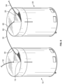
- a drum 10 has an end surface 11 and an outer surface 18.
- the example drum 10 is substantially cylindrical in shape.
- the drum 10 may be shaped, for example, as a hexagonal prism or octagonal prism.
- the example drum 10 comprises a drum body 12 and a drum lid 13.
- the drum 10 may be a single piece.
- the example drum lid 13 is removable from the drum body 12.
- the drum 10 may be made of a recyclable material, such as fiber or cardboard.
- the end surface 11 of the example drum 10 is a top surface (e.g., based on an intended orientation of the drum 10 when in use).
- the end surface 11 includes a wire feeding opening 14. Welding wire 30 passes through the wire feeding opening 14.
- the example wire feeding opening 14 is located in a central location of the end surface 11.
- the end surface 11 includes an access door 15.
- the access door 15 is defined by an area of the end surface 11 that extends from the wire feeding opening 14. In some examples, the access door 15 is substantially triangular or trapezoidal in shape.
- the access door 15 may include a sector (in the geometric sense) of the end surface 11 attached on an edge 16 of the access door 15 to the first end surface 11.
- One side of the access door 15 may be cut or otherwise detached from the end surface 11 to allow the edge 16 of the access door 15 to function as either a hinge, as shown in FIG. 2 or a detachment edge, as shown in FIG. 3 .
- the edge 16 When functioning as a hinge, the edge 16 allows the access door to pivot to enable access to an interior space 40 of the drum 10.
- the edge 16 when functioning as a detachment edge, the edge 16 allows the access door 15 to be removed to enable access to the interior space 40.
- the edge 16 may be scored or perforated to better enable the access door 15 to pivot about, or detach from, the edge 16.
- Adjacent the access door 15 may be located a finger hole 17. The finger hole 17 enables easier lifting of, or access to, the access door 15.
- the example drum 10 includes a hold-down bar opening 19 on an outer surface 18 of the drum 10.
- the hold-down bar opening 19 may extend through the drum lid 13, the drum body 12, or both.
- the hold-down bar opening 19 may be a hole, a slit, or any other appropriate geometry.
- the hold-down bar opening 19 allows for a portion of a hold-down bar 50 to extend beyond the outer surface 18 of the drum.
- the hold-down bar 50 limits movement of the welding wire 30, particularly during transport of the drum 10.
- the end of the hold-down bar 50 may be bent to prevent the hold-down bar 50 from inadvertently sliding into the drum 10 and to provide easier handling of the hold-down bar 50.
- the bend in the example hold-down bar 50 is 90 degrees, but may have a greater or lesser angle.
- a hold-down bar opening 19 provides for access to and removal of the hold-down bar 50 through the hold-down bar opening 19 without prior removal of the drum lid 13.
- the hold-down bar 50 is removed before beginning a welding process.
- the hold-down bar opening 19 may be used on a drum that is not used for a continuous welding process, including a drum that does not have an access door 15.
- such a drum could be prepared with a length of welding wire 30 protruding through a wire feeding opening 14 to allow a user to start a non-continuous welding process without first needing to remove the drum lid.
- the interior space 40 of the example drum 10 contains welding wire 30.
- the welding wire 30 has a starting (e.g., proximal) end 32 and a finishing (e.g., distal) end 34.
- the drum 10 is provided with the starting end 32 protruding through the wire feeding opening 14, with a majority of the welding wire located within the interior space 40 of the drum 10, including the finishing end 34.
- the access door 15 provides access to the finishing end 34 without need for removal of the end surface 11 or drum lid 13.
- An anti-tangle ball 35 may be threaded onto the welding wire 30, similar to how a needle may be threaded onto a length of thread.
- the anti-tangle ball 35 may be used to prevent kinks or bends forming in the wire during welding. The formation of kinks or bends can interrupt the wire feeding process, such that the welding process has to be stopped, which can have detrimental practical and economic consequences.
- the anti-tangle ball will advance along the length of the welding wire 30 from the starting end 32 towards the finishing end 34 as the welding wire 30 is drawn.
- the anti-tangle ball 35 will preferably be formed of a material that has a weight but that is sufficiently lightweight so as not to deform the welding wire 30.
- the anti-tangle ball 35 should be sized so that it can pass through the space in the end surface 11 defined by the access door 15.
- a second drum 20 may be placed in relative proximity to a first drum 10.
- the drums 10, 20 may be adjacent each other, or spaced further apart.
- the access door 15 of the first drum 10 may be placed adjacent the second drum 20.
- the second drum 20 may comprise an access door 25 to allow access to a second welding wire 60 contained in the second drum 20, including the finishing end 64 of the second welding wire 60.
- Each of the drums 10, 20 may comprise a hold-down bar 50, 70 (respectively) to limit movement of the welding wires 30, 60, particularly during transport.
- the hold-down bar 50, 70 for each drum should be removed before beginning a welding process.
- the hold-down bar 50 may be removed before retrieving the starting end 32 of the first welding wire 30.
- the hold-down bar 70 may be removed prior to retrieving the starting end 62 of the second welding wire 60.
- the finishing end 34 of a first welding wire 30 may be joined to the starting end 62 of a second welding wire 60.
- the welding wires 30, 60 may be joined by, for example, butt welding. Joining the welding wires 30, 60 allows for a continuous welding process. Towards the end of drawing the first welding wire 30, the anti-tangle ball 35 will advance along the finishing end 34 of the first welding wire 30 onto the starting end 64 of the second welding wire 60.
- the hold-down bar 50 may be removed through the hold-down bar opening 19 without having to first remove the drum lid 13, that it makes it easier to retrieve the finishing end 34 of welding wire 30 via the access door 15 without having to first remove the drum lid 13, and that the drum lid 13 may remain intact during welding (thus limiting the amount of dirt or debris that may enter the interior space 40 during welding).
- These advantages improve the efficiency of welding processes.
- continuous welding processes are made more efficient by using the hold-down bar opening 19 and the access door 15. Further, the risk of needing to stop a continuous welding process.
Landscapes
- Engineering & Computer Science (AREA)
- Mechanical Engineering (AREA)
- Physics & Mathematics (AREA)
- Plasma & Fusion (AREA)
- Storage Of Web-Like Or Filamentary Materials (AREA)
Claims (14)
- Trommel (10) zum Transportieren und Zuführen von Schweißdraht, wobeidie Trommel (10) einen Innenraum (40) definiert und eine erste Endfläche (11) aufweist,wobei der Innenraum (40) einen Draht (30) mit einem proximalen Ende (32) und einem distalen Ende (34) enthält, die um eine Längsachse gewickelt sind, einen Raum um die Längsachse definierend;dadurch gekennzeichnet, dass
die erste Endfläche (11) der Trommel (10) eine Zugangstür (15) aufweist, die zumindest teilweise durch einen Spalt in der ersten Endfläche (11) definiert ist, der sich von einer Drahtzuführöffnung (14) der ersten Endfläche (11) zu einem Umfang der Trommel (10) erstreckt, wobei das proximale Ende (32) des Drahts (30) durch die Drahtzuführöffnung (14) vorsteht, undwobei die Zugangstür (15) so konfiguriert ist, dass sie einen Zugang zu dem distalen Ende (34) des Drahts (30) in dem Innenraum (40) der Trommel (10) ermöglicht, wenn sie geöffnet oder von der ersten Endfläche (11) entfernt ist. - Trommel (10) nach Anspruch 1, wobei die Zugangstür (15) geöffnet werden kann, indem die Zugangstür (15) von der ersten Endfläche (11) weg um ein Scharnier geschwenkt wird, das durch die Grenzfläche zwischen der Zugangstür (15) und der ersten Endfläche (11) definiert ist.
- Trommel (10) nach Anspruch 1, wobei die Zugangstür (15) durch Lösen der Zugangstür (15) von der ersten Endfläche (11) entfernbar ist.
- Trommel (10) nach Anspruch 1, wobei die erste Endfläche (11) ferner ein Fingerloch (17) in Angrenzung an die Zugangstür (15) aufweist, um das Öffnen oder Entfernen der Zugangstür (15) zu unterstützen.
- Trommel (10) nach Anspruch 1, wobei eine verhedderungshemmende Kugel (35) auf den Draht (30) geschraubt ist, um zu verhindern, dass sich der Draht (30) verheddert oder versehentlich verformt, und wobei die Zugangstür (15) so dimensioniert ist, dass sie, wenn die Zugangstür (15) gelöst ist oder bewegt wird, ermöglicht, dass die verhedderungshemmende Kugel (35) über eine In-situ-Position der Zugangstür (15) an der ersten Endfläche (11) von der Trommel (10) entfernt wird.
- Trommel (10) nach Anspruch 1, ferner aufweisend:eine Außenfläche (18), die den Innenraum (40) definiert und um die Längsachse zentriert ist, sich entlang der Längsachse erstreckt und den Draht (30) zumindest im Wesentlichen umgibt; undeine Niederhaltestange (50), um die Bewegung des gewickelten Drahts (30) während des Transports zu begrenzen;wobei die Außenfläche (18) der Trommel (10) eine Niederhaltestangenöffnung (19) aufweist, um zu ermöglichen, dass zumindest ein Ende der Niederhaltestange (50) über die Außenfläche (18) der Trommel (10) hinaus vorsteht; undwobei die erste Endfläche (11) in einem Winkel zur Längsachse steht.
- Trommel (10) nach Anspruch 6, wobei die Niederhaltestange (50) eine Biegung aufweist, die über die Außenfläche hinaus vorsteht.
- Trommel (10) nach Anspruch 7, wobei die Biegung einen Winkel von 90 Grad aufweist.
- Trommel (10) nach Anspruch 6, wobei die Drahtzuführöffnung (14) in der Mitte der ersten Endfläche (11) angeordnet ist.
- Trommel (10) nach Anspruch 6, wobei die Trommel (10) eine Fibertrommel (10) aufweist.
- Trommel (10) nach Anspruch 1, wobei die Zugangstür (15) eine im Wesentlichen dreieckige oder trapezförmige Form aufweist; oder
wobei die Zugangstür (15) einen geometrischen Sektor der ersten Endfläche (11) aufweist, der an einer Kante der Zugangstür (15) an der ersten Endfläche (11) befestigt ist. - Trommel (10) nach Anspruch 1, die ferner eine verhedderungshemmende Kugel (35) aufweist, die auf den Draht (30) geschraubt ist, um zu verhindern, dass sich der Draht (30) verheddert oder versehentlich verformt.
- Trommel (10) nach Anspruch 12, wobei die Zugangstür (15) so dimensioniert ist, dass sie, wenn die Zugangstür (15) gelöst ist oder bewegt wird, ermöglicht, dass die verhedderungshemmende Kugel (35) über eine In-situ-Position der Zugangstür (15) an der ersten Endfläche (11) von der Trommel (10) entfernt wird.
- System zum Transportieren und Zuführen von Schweißdraht, das eine erste Trommel (10) und eine zweite Trommel (20) nach Anspruch 1 aufweist, wobei das distale Ende (34) des Drahts (30) der ersten Trommel (10) an das proximale Ende (62) des Drahts (60) der zweiten Trommel (20) geschweißt ist.
Applications Claiming Priority (2)
| Application Number | Priority Date | Filing Date | Title |
|---|---|---|---|
| US15/616,680 US10703557B2 (en) | 2017-06-07 | 2017-06-07 | Drums for transporting and feeding wire |
| PCT/US2018/035096 WO2018226480A1 (en) | 2017-06-07 | 2018-05-30 | Drums for transporting and feeding wire |
Publications (2)
| Publication Number | Publication Date |
|---|---|
| EP3634895A1 EP3634895A1 (de) | 2020-04-15 |
| EP3634895B1 true EP3634895B1 (de) | 2023-07-05 |
Family
ID=62751544
Family Applications (1)
| Application Number | Title | Priority Date | Filing Date |
|---|---|---|---|
| EP18734676.2A Active EP3634895B1 (de) | 2017-06-07 | 2018-05-30 | Trommeln zum transportieren und zuführen von draht |
Country Status (6)
| Country | Link |
|---|---|
| US (1) | US10703557B2 (de) |
| EP (1) | EP3634895B1 (de) |
| CN (1) | CN110997536B (de) |
| CA (1) | CA3066385C (de) |
| MX (1) | MX391262B (de) |
| WO (1) | WO2018226480A1 (de) |
Families Citing this family (11)
| Publication number | Priority date | Publication date | Assignee | Title |
|---|---|---|---|---|
| USD902991S1 (en) * | 2018-12-20 | 2020-11-24 | Hewlett-Packard Development Company, L.P. | Printer |
| USD926707S1 (en) * | 2019-08-13 | 2021-08-03 | BL United, LLC | Modular conduit cable management assembly |
| USD952750S1 (en) | 2019-10-11 | 2022-05-24 | Sg Gaming, Inc. | Gaming machine |
| USD952755S1 (en) | 2019-10-11 | 2022-05-24 | Sg Gaming, Inc. | Gaming machine |
| USD952753S1 (en) * | 2019-10-11 | 2022-05-24 | Sg Gaming, Inc. | Gaming machine |
| USD952754S1 (en) | 2019-10-11 | 2022-05-24 | Sg Gaming, Inc. | Gaming machine |
| USD952752S1 (en) * | 2019-10-11 | 2022-05-24 | Sg Gaming, Inc. | Gaming machine |
| USD952751S1 (en) | 2019-10-11 | 2022-05-24 | Sg Gaming, Inc. | Gaming machine |
| KR102351609B1 (ko) * | 2020-06-26 | 2022-01-18 | 고려용접봉 주식회사 | 용접 와이어 수납용기용 덮개 |
| KR102398582B1 (ko) * | 2020-08-18 | 2022-05-17 | 고려용접봉 주식회사 | 용접 와이어용 수납 용기 |
| US20250026607A1 (en) * | 2022-02-16 | 2025-01-23 | Fujikura Ltd. | Cable accommodating body |
Family Cites Families (57)
| Publication number | Priority date | Publication date | Assignee | Title |
|---|---|---|---|---|
| US439622A (en) | 1890-11-04 | Tom albert bastin | ||
| GB404114A (en) | 1932-11-02 | 1934-01-11 | William Hollins & Company Ltd | Improvements in cartons for containing wool yarns and the like |
| US2713938A (en) * | 1950-04-26 | 1955-07-26 | New Bedford Cordage Company | Rope package |
| US2867319A (en) | 1955-10-06 | 1959-01-06 | Continental Can Co | Strand packaging method and means |
| US3014577A (en) | 1960-06-03 | 1961-12-26 | Syncro Mach Co | Container for coils of wire |
| US3246815A (en) | 1964-09-02 | 1966-04-19 | Woltra Company Inc | Dental floss dispenser |
| US3602455A (en) * | 1969-12-08 | 1971-08-31 | Charles W Lewis | Wire dispenser |
| US3998326A (en) * | 1976-01-29 | 1976-12-21 | Ppg Industries, Inc. | Packaging forming packages of strand material |
| USD256999S (en) | 1977-12-20 | 1980-09-23 | Alcar Industries | Twist tie dispenser |
| USD257321S (en) | 1978-06-01 | 1980-10-14 | Voorhees Jr James M | Support for cables, tubing or the like |
| USD256370S (en) | 1978-07-12 | 1980-08-12 | Texas Instruments Incorporated | Case for hand-held electronic calculator |
| US4451014A (en) | 1982-08-11 | 1984-05-29 | Mossberg Industries, Inc. | Wire storing and dereeling apparatus |
| US4591110A (en) | 1984-07-27 | 1986-05-27 | Mossberg Industries | Wire storing and dereeling apparatus |
| US4623063A (en) * | 1986-01-29 | 1986-11-18 | Balkin Michael L | Fibreboard container for coil material |
| USD313340S (en) | 1988-07-05 | 1991-01-01 | Doug Mockett and Company, Inc. | Cord access grommet set for office furniture use |
| US4914792A (en) | 1988-12-16 | 1990-04-10 | Bradt Jeffrey A | Line securing device |
| US5103977A (en) * | 1990-01-02 | 1992-04-14 | Douglas Frank A | Portable container for elongated elements |
| US5165543A (en) * | 1991-09-25 | 1992-11-24 | At&T Bell Laboratories | Protected optical fiber package |
| US5299706A (en) * | 1992-05-26 | 1994-04-05 | Cooper Industries, Inc. | Pail lid |
| IT231566Y1 (it) * | 1993-02-23 | 1999-08-04 | Sidergas Srl | Contenitore di imballaggio e di svolgimento di una matassa di filo metallico |
| IT234995Y1 (it) | 1994-06-22 | 2000-03-31 | Bocchiotti Soc Ind Elettrotec | Imballaggio per tubi o guaine flessibili. |
| USD395950S (en) | 1996-08-12 | 1998-07-14 | J. R. Duffy Inc. | Cord dispenser |
| USD428796S (en) | 1996-10-11 | 2000-08-01 | Stork Rms B.V. | Support for cattle for slaughter |
| US5738209A (en) * | 1996-12-23 | 1998-04-14 | General Motors Corporation | Cable storage container |
| US6016911A (en) * | 1999-02-19 | 2000-01-25 | Chen; Hua-Mei | Package for a reel of wire |
| DE69910357T2 (de) * | 1999-05-31 | 2004-04-29 | C.I.F.E. S.R.L., Chiusi Della Verna | Aus Karton hergestellte Faltschachtel zur Aufnahme und Abgabe von Draht |
| USD450563S1 (en) | 2000-08-07 | 2001-11-20 | Quick Industries, Inc. | Container for dispensing string |
| SE0101749L (sv) | 2001-05-18 | 2002-04-23 | Esab Ab | Anordning vid svetstrådsmatning, trådorienteringslöpare, metod och användning |
| US6715608B1 (en) | 2001-11-06 | 2004-04-06 | Lincoln Global, Inc. | Package for welding wire |
| US6968955B2 (en) | 2004-01-07 | 2005-11-29 | Dorian Steeber | Electric extension cord storage device |
| US7191968B2 (en) * | 2004-05-19 | 2007-03-20 | National Standard Company | System for handling welding wire and method of handling welding wire using the system |
| CA2486429A1 (en) * | 2004-06-01 | 2005-12-01 | Berwick Delaware, Inc. | Storage spool |
| US7222734B2 (en) * | 2004-07-15 | 2007-05-29 | Lincoln Global, Inc. | Welding wire package with lifting strap |
| US20060196989A1 (en) * | 2005-03-04 | 2006-09-07 | Harold Bartley | Stackable dispenser for coiled materials |
| US20060196794A1 (en) * | 2005-03-07 | 2006-09-07 | Lincoln Global, Inc. | Welding wire container and method of making the same |
| US20060249611A1 (en) * | 2005-05-03 | 2006-11-09 | Lincoln Global, Inc. | Endless wire container and method of using the same |
| USD569349S1 (en) | 2006-01-10 | 2008-05-20 | Ryan Preston | Clamp for extension cord |
| KR100912861B1 (ko) * | 2007-10-29 | 2009-08-19 | 현대종합금속 주식회사 | 용접와이어 엉킴방지장치 |
| EP2174741B1 (de) * | 2008-10-07 | 2012-06-20 | SIDERGAS SpA | Abdeckung für einen Schweißdrahtbehälter |
| US8235210B2 (en) * | 2009-04-27 | 2012-08-07 | Lincoln Global, Inc. | Welding wire container cover and container containing same |
| US8167102B2 (en) | 2009-08-13 | 2012-05-01 | Hewlett-Packard Development Company, L.P. | Cable spool for carrying connectivity cable for mobile computing devices |
| JP5618360B2 (ja) * | 2010-09-30 | 2014-11-05 | 株式会社ダイヘン | 溶接ワイヤ送給装置 |
| FR2969940A1 (fr) | 2011-01-04 | 2012-07-06 | Air Liquide Welding France | Fut pour bobine de fil de soudage |
| US20120168554A1 (en) * | 2011-01-04 | 2012-07-05 | Randy Blunt | System for storing a bulk supply of cable for controlled payout and method of using the system |
| EP2476501A1 (de) * | 2011-01-13 | 2012-07-18 | SIDERGAS SpA | Schweißdrahtring und Behälter mit einem Schweißdrahtring |
| US8689975B2 (en) * | 2011-06-29 | 2014-04-08 | Lincoln Global, Inc. | Bulk wire isolator apparatus |
| US8936210B2 (en) | 2011-11-16 | 2015-01-20 | Illinois Tool Works Inc. | Floating dispensing mechanism for drum packed welding wire |
| USD682909S1 (en) | 2012-01-31 | 2013-05-21 | Samsung Electronics Co., Ltd. | Straps connector |
| USD695524S1 (en) | 2012-03-02 | 2013-12-17 | Scott A. Manderino | Container for a string used on a weed eater |
| EP2845281A4 (de) * | 2012-04-30 | 2015-12-23 | Adc Telecommunications Inc | Kabelaufnahmespule mit mittigem einzug |
| US8931638B2 (en) * | 2013-03-14 | 2015-01-13 | Lincoln Global, Inc. | System for packaging a coiled product |
| USD727854S1 (en) | 2013-03-15 | 2015-04-28 | Stout Stuff, Llc | Cable crimp cover |
| USD698228S1 (en) | 2013-03-15 | 2014-01-28 | Stout Stuff, Llc | Cable crimp cover |
| USD707106S1 (en) | 2013-10-17 | 2014-06-17 | Wanho T Manufacturing Co., Ltd. | Cable organizing device |
| US10118755B2 (en) | 2015-02-18 | 2018-11-06 | Quikcord Inc. | Parachord dispenser and associated methods |
| USD803666S1 (en) | 2016-05-05 | 2017-11-28 | Izzy Industries Inc. | Cable organizer |
| AU201616678S (en) | 2016-06-01 | 2017-02-14 | Vuitton Louis Sa | Cylindres |
-
2017
- 2017-06-07 US US15/616,680 patent/US10703557B2/en active Active
-
2018
- 2018-05-30 EP EP18734676.2A patent/EP3634895B1/de active Active
- 2018-05-30 CA CA3066385A patent/CA3066385C/en active Active
- 2018-05-30 CN CN201880037728.8A patent/CN110997536B/zh active Active
- 2018-05-30 MX MX2019014591A patent/MX391262B/es unknown
- 2018-05-30 WO PCT/US2018/035096 patent/WO2018226480A1/en not_active Ceased
Also Published As
| Publication number | Publication date |
|---|---|
| US10703557B2 (en) | 2020-07-07 |
| MX2019014591A (es) | 2020-02-07 |
| US20180354710A1 (en) | 2018-12-13 |
| CN110997536A (zh) | 2020-04-10 |
| CA3066385C (en) | 2022-11-29 |
| CN110997536B (zh) | 2021-10-22 |
| WO2018226480A1 (en) | 2018-12-13 |
| CA3066385A1 (en) | 2018-12-13 |
| EP3634895A1 (de) | 2020-04-15 |
| MX391262B (es) | 2025-03-21 |
Similar Documents
| Publication | Publication Date | Title |
|---|---|---|
| CA3066385C (en) | Drums for transporting and feeding wire | |
| US6648141B2 (en) | Packaging for containing and dispensing large quantities of wire | |
| EP2354039A1 (de) | Behälter für Schweißdraht mit interner Halterung | |
| EP0636098A1 (de) | Behälter zum verpacken und abwickeln einer drahtrolle | |
| US9499300B2 (en) | Closure for an easy opening container and a container provided with such closure | |
| US2149087A (en) | Protective rod and reel case | |
| SE1050036A1 (sv) | Styrring för svetstråd | |
| US20080142626A1 (en) | Pail-Pack for Welding Wire | |
| CN100384702C (zh) | 具有提带的焊丝包装 | |
| US20140246532A1 (en) | Endless wire container and method of using same | |
| CN103771005B (zh) | 具有用于焊丝线圈的提升带的容器 | |
| EP2353764A1 (de) | Behälter für Schweißdraht mit internem Totvolumen von mindestens 15 cm hoch | |
| EP2612833A1 (de) | Schweißdrahtbehälter mit einem vom Draht durchquerten gleitenden Gewichtselement | |
| KR102526934B1 (ko) | 개선된 친환경 플라스틱 병뚜껑 | |
| US9162846B2 (en) | Slip lift core for drums | |
| EP4186837B1 (de) | Schweissdrahtspule mit abreisslasche | |
| JPS63147781A (ja) | 溶接用パツクワイヤ | |
| FR2969940A1 (fr) | Fut pour bobine de fil de soudage | |
| EP3533552A1 (de) | Gurtführung und eimerpack damit | |
| WO2006112923A1 (en) | Removable-panel metal end with cut protection | |
| US2741394A (en) | Tear strip guides | |
| KR200489914Y1 (ko) | 배송 상자 | |
| KR20200110248A (ko) | 마감용 라이너 유닛을 구비한 테이핑 장치 | |
| JP6025454B2 (ja) | 包装用箱 | |
| JP4760435B2 (ja) | 缶用オーバーキャップ |
Legal Events
| Date | Code | Title | Description |
|---|---|---|---|
| STAA | Information on the status of an ep patent application or granted ep patent |
Free format text: STATUS: UNKNOWN |
|
| STAA | Information on the status of an ep patent application or granted ep patent |
Free format text: STATUS: THE INTERNATIONAL PUBLICATION HAS BEEN MADE |
|
| PUAI | Public reference made under article 153(3) epc to a published international application that has entered the european phase |
Free format text: ORIGINAL CODE: 0009012 |
|
| STAA | Information on the status of an ep patent application or granted ep patent |
Free format text: STATUS: REQUEST FOR EXAMINATION WAS MADE |
|
| 17P | Request for examination filed |
Effective date: 20191216 |
|
| AK | Designated contracting states |
Kind code of ref document: A1 Designated state(s): AL AT BE BG CH CY CZ DE DK EE ES FI FR GB GR HR HU IE IS IT LI LT LU LV MC MK MT NL NO PL PT RO RS SE SI SK SM TR |
|
| AX | Request for extension of the european patent |
Extension state: BA ME |
|
| DAV | Request for validation of the european patent (deleted) | ||
| DAX | Request for extension of the european patent (deleted) | ||
| STAA | Information on the status of an ep patent application or granted ep patent |
Free format text: STATUS: EXAMINATION IS IN PROGRESS |
|
| 17Q | First examination report despatched |
Effective date: 20210111 |
|
| GRAP | Despatch of communication of intention to grant a patent |
Free format text: ORIGINAL CODE: EPIDOSNIGR1 |
|
| STAA | Information on the status of an ep patent application or granted ep patent |
Free format text: STATUS: GRANT OF PATENT IS INTENDED |
|
| INTG | Intention to grant announced |
Effective date: 20230228 |
|
| GRAS | Grant fee paid |
Free format text: ORIGINAL CODE: EPIDOSNIGR3 |
|
| GRAA | (expected) grant |
Free format text: ORIGINAL CODE: 0009210 |
|
| STAA | Information on the status of an ep patent application or granted ep patent |
Free format text: STATUS: THE PATENT HAS BEEN GRANTED |
|
| AK | Designated contracting states |
Kind code of ref document: B1 Designated state(s): AL AT BE BG CH CY CZ DE DK EE ES FI FR GB GR HR HU IE IS IT LI LT LU LV MC MK MT NL NO PL PT RO RS SE SI SK SM TR |
|
| P01 | Opt-out of the competence of the unified patent court (upc) registered |
Effective date: 20230606 |
|
| REG | Reference to a national code |
Ref country code: CH Ref legal event code: EP |
|
| REG | Reference to a national code |
Ref country code: AT Ref legal event code: REF Ref document number: 1584687 Country of ref document: AT Kind code of ref document: T Effective date: 20230715 |
|
| REG | Reference to a national code |
Ref country code: DE Ref legal event code: R096 Ref document number: 602018052829 Country of ref document: DE |
|
| REG | Reference to a national code |
Ref country code: IE Ref legal event code: FG4D |
|
| REG | Reference to a national code |
Ref country code: LT Ref legal event code: MG9D |
|
| REG | Reference to a national code |
Ref country code: NL Ref legal event code: MP Effective date: 20230705 |
|
| REG | Reference to a national code |
Ref country code: AT Ref legal event code: MK05 Ref document number: 1584687 Country of ref document: AT Kind code of ref document: T Effective date: 20230705 |
|
| PG25 | Lapsed in a contracting state [announced via postgrant information from national office to epo] |
Ref country code: NL Free format text: LAPSE BECAUSE OF FAILURE TO SUBMIT A TRANSLATION OF THE DESCRIPTION OR TO PAY THE FEE WITHIN THE PRESCRIBED TIME-LIMIT Effective date: 20230705 |
|
| PG25 | Lapsed in a contracting state [announced via postgrant information from national office to epo] |
Ref country code: GR Free format text: LAPSE BECAUSE OF FAILURE TO SUBMIT A TRANSLATION OF THE DESCRIPTION OR TO PAY THE FEE WITHIN THE PRESCRIBED TIME-LIMIT Effective date: 20231006 |
|
| PG25 | Lapsed in a contracting state [announced via postgrant information from national office to epo] |
Ref country code: ES Free format text: LAPSE BECAUSE OF FAILURE TO SUBMIT A TRANSLATION OF THE DESCRIPTION OR TO PAY THE FEE WITHIN THE PRESCRIBED TIME-LIMIT Effective date: 20230705 |
|
| PG25 | Lapsed in a contracting state [announced via postgrant information from national office to epo] |
Ref country code: IS Free format text: LAPSE BECAUSE OF FAILURE TO SUBMIT A TRANSLATION OF THE DESCRIPTION OR TO PAY THE FEE WITHIN THE PRESCRIBED TIME-LIMIT Effective date: 20231105 |
|
| PG25 | Lapsed in a contracting state [announced via postgrant information from national office to epo] |
Ref country code: SE Free format text: LAPSE BECAUSE OF FAILURE TO SUBMIT A TRANSLATION OF THE DESCRIPTION OR TO PAY THE FEE WITHIN THE PRESCRIBED TIME-LIMIT Effective date: 20230705 Ref country code: RS Free format text: LAPSE BECAUSE OF FAILURE TO SUBMIT A TRANSLATION OF THE DESCRIPTION OR TO PAY THE FEE WITHIN THE PRESCRIBED TIME-LIMIT Effective date: 20230705 Ref country code: PT Free format text: LAPSE BECAUSE OF FAILURE TO SUBMIT A TRANSLATION OF THE DESCRIPTION OR TO PAY THE FEE WITHIN THE PRESCRIBED TIME-LIMIT Effective date: 20231106 Ref country code: NO Free format text: LAPSE BECAUSE OF FAILURE TO SUBMIT A TRANSLATION OF THE DESCRIPTION OR TO PAY THE FEE WITHIN THE PRESCRIBED TIME-LIMIT Effective date: 20231005 Ref country code: LV Free format text: LAPSE BECAUSE OF FAILURE TO SUBMIT A TRANSLATION OF THE DESCRIPTION OR TO PAY THE FEE WITHIN THE PRESCRIBED TIME-LIMIT Effective date: 20230705 Ref country code: LT Free format text: LAPSE BECAUSE OF FAILURE TO SUBMIT A TRANSLATION OF THE DESCRIPTION OR TO PAY THE FEE WITHIN THE PRESCRIBED TIME-LIMIT Effective date: 20230705 Ref country code: IS Free format text: LAPSE BECAUSE OF FAILURE TO SUBMIT A TRANSLATION OF THE DESCRIPTION OR TO PAY THE FEE WITHIN THE PRESCRIBED TIME-LIMIT Effective date: 20231105 Ref country code: HR Free format text: LAPSE BECAUSE OF FAILURE TO SUBMIT A TRANSLATION OF THE DESCRIPTION OR TO PAY THE FEE WITHIN THE PRESCRIBED TIME-LIMIT Effective date: 20230705 Ref country code: GR Free format text: LAPSE BECAUSE OF FAILURE TO SUBMIT A TRANSLATION OF THE DESCRIPTION OR TO PAY THE FEE WITHIN THE PRESCRIBED TIME-LIMIT Effective date: 20231006 Ref country code: FI Free format text: LAPSE BECAUSE OF FAILURE TO SUBMIT A TRANSLATION OF THE DESCRIPTION OR TO PAY THE FEE WITHIN THE PRESCRIBED TIME-LIMIT Effective date: 20230705 Ref country code: ES Free format text: LAPSE BECAUSE OF FAILURE TO SUBMIT A TRANSLATION OF THE DESCRIPTION OR TO PAY THE FEE WITHIN THE PRESCRIBED TIME-LIMIT Effective date: 20230705 Ref country code: AT Free format text: LAPSE BECAUSE OF FAILURE TO SUBMIT A TRANSLATION OF THE DESCRIPTION OR TO PAY THE FEE WITHIN THE PRESCRIBED TIME-LIMIT Effective date: 20230705 |
|
| PG25 | Lapsed in a contracting state [announced via postgrant information from national office to epo] |
Ref country code: PL Free format text: LAPSE BECAUSE OF FAILURE TO SUBMIT A TRANSLATION OF THE DESCRIPTION OR TO PAY THE FEE WITHIN THE PRESCRIBED TIME-LIMIT Effective date: 20230705 |
|
| REG | Reference to a national code |
Ref country code: DE Ref legal event code: R097 Ref document number: 602018052829 Country of ref document: DE |
|
| PG25 | Lapsed in a contracting state [announced via postgrant information from national office to epo] |
Ref country code: SM Free format text: LAPSE BECAUSE OF FAILURE TO SUBMIT A TRANSLATION OF THE DESCRIPTION OR TO PAY THE FEE WITHIN THE PRESCRIBED TIME-LIMIT Effective date: 20230705 Ref country code: RO Free format text: LAPSE BECAUSE OF FAILURE TO SUBMIT A TRANSLATION OF THE DESCRIPTION OR TO PAY THE FEE WITHIN THE PRESCRIBED TIME-LIMIT Effective date: 20230705 Ref country code: EE Free format text: LAPSE BECAUSE OF FAILURE TO SUBMIT A TRANSLATION OF THE DESCRIPTION OR TO PAY THE FEE WITHIN THE PRESCRIBED TIME-LIMIT Effective date: 20230705 Ref country code: DK Free format text: LAPSE BECAUSE OF FAILURE TO SUBMIT A TRANSLATION OF THE DESCRIPTION OR TO PAY THE FEE WITHIN THE PRESCRIBED TIME-LIMIT Effective date: 20230705 Ref country code: CZ Free format text: LAPSE BECAUSE OF FAILURE TO SUBMIT A TRANSLATION OF THE DESCRIPTION OR TO PAY THE FEE WITHIN THE PRESCRIBED TIME-LIMIT Effective date: 20230705 Ref country code: SK Free format text: LAPSE BECAUSE OF FAILURE TO SUBMIT A TRANSLATION OF THE DESCRIPTION OR TO PAY THE FEE WITHIN THE PRESCRIBED TIME-LIMIT Effective date: 20230705 |
|
| PLBE | No opposition filed within time limit |
Free format text: ORIGINAL CODE: 0009261 |
|
| STAA | Information on the status of an ep patent application or granted ep patent |
Free format text: STATUS: NO OPPOSITION FILED WITHIN TIME LIMIT |
|
| PG25 | Lapsed in a contracting state [announced via postgrant information from national office to epo] |
Ref country code: IT Free format text: LAPSE BECAUSE OF FAILURE TO SUBMIT A TRANSLATION OF THE DESCRIPTION OR TO PAY THE FEE WITHIN THE PRESCRIBED TIME-LIMIT Effective date: 20230705 |
|
| 26N | No opposition filed |
Effective date: 20240408 |
|
| PG25 | Lapsed in a contracting state [announced via postgrant information from national office to epo] |
Ref country code: SI Free format text: LAPSE BECAUSE OF FAILURE TO SUBMIT A TRANSLATION OF THE DESCRIPTION OR TO PAY THE FEE WITHIN THE PRESCRIBED TIME-LIMIT Effective date: 20230705 |
|
| PG25 | Lapsed in a contracting state [announced via postgrant information from national office to epo] |
Ref country code: BG Free format text: LAPSE BECAUSE OF FAILURE TO SUBMIT A TRANSLATION OF THE DESCRIPTION OR TO PAY THE FEE WITHIN THE PRESCRIBED TIME-LIMIT Effective date: 20230705 |
|
| PG25 | Lapsed in a contracting state [announced via postgrant information from national office to epo] |
Ref country code: BG Free format text: LAPSE BECAUSE OF FAILURE TO SUBMIT A TRANSLATION OF THE DESCRIPTION OR TO PAY THE FEE WITHIN THE PRESCRIBED TIME-LIMIT Effective date: 20230705 |
|
| REG | Reference to a national code |
Ref country code: CH Ref legal event code: PL |
|
| PG25 | Lapsed in a contracting state [announced via postgrant information from national office to epo] |
Ref country code: MC Free format text: LAPSE BECAUSE OF FAILURE TO SUBMIT A TRANSLATION OF THE DESCRIPTION OR TO PAY THE FEE WITHIN THE PRESCRIBED TIME-LIMIT Effective date: 20230705 |
|
| PG25 | Lapsed in a contracting state [announced via postgrant information from national office to epo] |
Ref country code: LU Free format text: LAPSE BECAUSE OF NON-PAYMENT OF DUE FEES Effective date: 20240530 |
|
| GBPC | Gb: european patent ceased through non-payment of renewal fee |
Effective date: 20240530 |
|
| PG25 | Lapsed in a contracting state [announced via postgrant information from national office to epo] |
Ref country code: MC Free format text: LAPSE BECAUSE OF FAILURE TO SUBMIT A TRANSLATION OF THE DESCRIPTION OR TO PAY THE FEE WITHIN THE PRESCRIBED TIME-LIMIT Effective date: 20230705 Ref country code: LU Free format text: LAPSE BECAUSE OF NON-PAYMENT OF DUE FEES Effective date: 20240530 Ref country code: CH Free format text: LAPSE BECAUSE OF NON-PAYMENT OF DUE FEES Effective date: 20240531 |
|
| REG | Reference to a national code |
Ref country code: BE Ref legal event code: MM Effective date: 20240531 |
|
| PG25 | Lapsed in a contracting state [announced via postgrant information from national office to epo] |
Ref country code: IE Free format text: LAPSE BECAUSE OF NON-PAYMENT OF DUE FEES Effective date: 20240530 |
|
| PG25 | Lapsed in a contracting state [announced via postgrant information from national office to epo] |
Ref country code: BE Free format text: LAPSE BECAUSE OF NON-PAYMENT OF DUE FEES Effective date: 20240531 |
|
| PG25 | Lapsed in a contracting state [announced via postgrant information from national office to epo] |
Ref country code: FR Free format text: LAPSE BECAUSE OF NON-PAYMENT OF DUE FEES Effective date: 20240531 |
|
| PG25 | Lapsed in a contracting state [announced via postgrant information from national office to epo] |
Ref country code: GB Free format text: LAPSE BECAUSE OF NON-PAYMENT OF DUE FEES Effective date: 20240530 |
|
| PGFP | Annual fee paid to national office [announced via postgrant information from national office to epo] |
Ref country code: DE Payment date: 20250529 Year of fee payment: 8 |
|
| PG25 | Lapsed in a contracting state [announced via postgrant information from national office to epo] |
Ref country code: CY Free format text: LAPSE BECAUSE OF FAILURE TO SUBMIT A TRANSLATION OF THE DESCRIPTION OR TO PAY THE FEE WITHIN THE PRESCRIBED TIME-LIMIT; INVALID AB INITIO Effective date: 20180530 |
|
| PG25 | Lapsed in a contracting state [announced via postgrant information from national office to epo] |
Ref country code: HU Free format text: LAPSE BECAUSE OF FAILURE TO SUBMIT A TRANSLATION OF THE DESCRIPTION OR TO PAY THE FEE WITHIN THE PRESCRIBED TIME-LIMIT; INVALID AB INITIO Effective date: 20180530 |