EP3635888B1 - Dispositif de communication sans fil, équipement d'infrastructure et méthodes - Google Patents
Dispositif de communication sans fil, équipement d'infrastructure et méthodes Download PDFInfo
- Publication number
- EP3635888B1 EP3635888B1 EP18728560.6A EP18728560A EP3635888B1 EP 3635888 B1 EP3635888 B1 EP 3635888B1 EP 18728560 A EP18728560 A EP 18728560A EP 3635888 B1 EP3635888 B1 EP 3635888B1
- Authority
- EP
- European Patent Office
- Prior art keywords
- synchronisation signal
- ofdm symbols
- signal block
- synchronisation
- wireless communications
- Prior art date
- Legal status (The legal status is an assumption and is not a legal conclusion. Google has not performed a legal analysis and makes no representation as to the accuracy of the status listed.)
- Active
Links
Images




Classifications
-
- H—ELECTRICITY
- H04—ELECTRIC COMMUNICATION TECHNIQUE
- H04J—MULTIPLEX COMMUNICATION
- H04J11/00—Orthogonal multiplex systems, e.g. using WALSH codes
- H04J11/0069—Cell search, i.e. determining cell identity [cell-ID]
- H04J11/0079—Acquisition of downlink reference signals, e.g. detection of cell-ID
-
- H—ELECTRICITY
- H04—ELECTRIC COMMUNICATION TECHNIQUE
- H04B—TRANSMISSION
- H04B7/00—Radio transmission systems, i.e. using radiation field
- H04B7/02—Diversity systems; Multi-antenna system, i.e. transmission or reception using multiple antennas
- H04B7/04—Diversity systems; Multi-antenna system, i.e. transmission or reception using multiple antennas using two or more spaced independent antennas
- H04B7/06—Diversity systems; Multi-antenna system, i.e. transmission or reception using multiple antennas using two or more spaced independent antennas at the transmitting station
- H04B7/0686—Hybrid systems, i.e. switching and simultaneous transmission
- H04B7/0695—Hybrid systems, i.e. switching and simultaneous transmission using beam selection
- H04B7/06952—Selecting one or more beams from a plurality of beams, e.g. beam training, management or sweeping
-
- H—ELECTRICITY
- H04—ELECTRIC COMMUNICATION TECHNIQUE
- H04L—TRANSMISSION OF DIGITAL INFORMATION, e.g. TELEGRAPHIC COMMUNICATION
- H04L27/00—Modulated-carrier systems
- H04L27/26—Systems using multi-frequency codes
- H04L27/2601—Multicarrier modulation systems
- H04L27/2602—Signal structure
- H04L27/261—Details of reference signals
- H04L27/2613—Structure of the reference signals
-
- H—ELECTRICITY
- H04—ELECTRIC COMMUNICATION TECHNIQUE
- H04L—TRANSMISSION OF DIGITAL INFORMATION, e.g. TELEGRAPHIC COMMUNICATION
- H04L27/00—Modulated-carrier systems
- H04L27/26—Systems using multi-frequency codes
- H04L27/2601—Multicarrier modulation systems
- H04L27/2647—Arrangements specific to the receiver only
- H04L27/2655—Synchronisation arrangements
-
- H—ELECTRICITY
- H04—ELECTRIC COMMUNICATION TECHNIQUE
- H04L—TRANSMISSION OF DIGITAL INFORMATION, e.g. TELEGRAPHIC COMMUNICATION
- H04L27/00—Modulated-carrier systems
- H04L27/26—Systems using multi-frequency codes
- H04L27/2601—Multicarrier modulation systems
- H04L27/2647—Arrangements specific to the receiver only
- H04L27/2655—Synchronisation arrangements
- H04L27/2689—Link with other circuits, i.e. special connections between synchronisation arrangements and other circuits for achieving synchronisation
- H04L27/2692—Link with other circuits, i.e. special connections between synchronisation arrangements and other circuits for achieving synchronisation with preamble design, i.e. with negotiation of the synchronisation sequence with transmitter or sequence linked to the algorithm used at the receiver
-
- H—ELECTRICITY
- H04—ELECTRIC COMMUNICATION TECHNIQUE
- H04L—TRANSMISSION OF DIGITAL INFORMATION, e.g. TELEGRAPHIC COMMUNICATION
- H04L5/00—Arrangements affording multiple use of the transmission path
- H04L5/0001—Arrangements for dividing the transmission path
- H04L5/0003—Two-dimensional division
- H04L5/0005—Time-frequency
- H04L5/0007—Time-frequency the frequencies being orthogonal, e.g. OFDM(A) or DMT
-
- H—ELECTRICITY
- H04—ELECTRIC COMMUNICATION TECHNIQUE
- H04L—TRANSMISSION OF DIGITAL INFORMATION, e.g. TELEGRAPHIC COMMUNICATION
- H04L5/00—Arrangements affording multiple use of the transmission path
- H04L5/0001—Arrangements for dividing the transmission path
- H04L5/0014—Three-dimensional division
- H04L5/0023—Time-frequency-space
-
- H—ELECTRICITY
- H04—ELECTRIC COMMUNICATION TECHNIQUE
- H04L—TRANSMISSION OF DIGITAL INFORMATION, e.g. TELEGRAPHIC COMMUNICATION
- H04L5/00—Arrangements affording multiple use of the transmission path
- H04L5/003—Arrangements for allocating sub-channels of the transmission path
- H04L5/0048—Allocation of pilot signals, i.e. of signals known to the receiver
-
- H—ELECTRICITY
- H04—ELECTRIC COMMUNICATION TECHNIQUE
- H04L—TRANSMISSION OF DIGITAL INFORMATION, e.g. TELEGRAPHIC COMMUNICATION
- H04L5/00—Arrangements affording multiple use of the transmission path
- H04L5/003—Arrangements for allocating sub-channels of the transmission path
- H04L5/0053—Allocation of signalling, i.e. of overhead other than pilot signals
-
- H—ELECTRICITY
- H04—ELECTRIC COMMUNICATION TECHNIQUE
- H04W—WIRELESS COMMUNICATION NETWORKS
- H04W56/00—Synchronisation arrangements
- H04W56/001—Synchronization between nodes
Definitions
- fourth generation networks can support communications at high data rate and low latencies from devices such as smart phones and tablet computers
- future wireless communications networks will be expected to efficiently support communications with a much wider range of devices associated with a wider range of data traffic profiles, for example including reduced complexity devices, machine type communication devices, high resolution video displays and virtual reality headsets.
- Some of these different types of devices may be deployed in very large numbers, for example low complexity devices for supporting the "The Internet of Things", and may typically be associated with the transmissions of relatively small amounts of data with relatively high latency tolerance, whereas other types of device, for example supporting high-definition video streaming, may be associated with transmissions of relatively large amounts of data with relatively low latency tolerance.
- new radio access technology which may be denoted new RAT or, simply, NR
- new RAT new radio access technology
- a wireless communications device for transmitting or receiving data via a wireless communications network as defined in the appended claims.
- Embodiments of the present technique further relate to infrastructure equipment, methods of operating communications devices, and methods of operating infrastructure equipment as defined in the appended claims. Respective aspects and features of the present disclosure are defined in the appended claims.
- Figure 1 provides a schematic diagram illustrating some basic functionality of a mobile telecommunications network / system operating in accordance with LTE principles and which may be adapted to implement embodiments of the disclosure as described further below.
- Various elements of Figure 1 and their respective modes of operation are well-known and defined in the relevant standards administered by the 3GPP (RTM) body, and also described in many books on the subject, for example, Holma H. and Toskala A [1].
- the network 100 includes a plurality of base stations 101 connected to a core network 102.
- Each base station provides a coverage area 103 (i.e. a cell) within which data can be communicated to and from communications devices 104.
- Data is transmitted from base stations 101 to communications devices 104 within their respective coverage areas 103 via a radio downlink.
- Data is transmitted from communications devices 104 to the base stations 101 via a radio uplink.
- the uplink and downlink communications are made using radio resources that are licenced for exclusive use by the operator of the network 100.
- the core network 102 routes data to and from the communications devices 104 via the respective base stations 101 and provides functions such as authentication, mobility management, charging and so on.
- Wireless communications systems such as those arranged in accordance with the 3GPP defined Long Term Evolution (LIE) architecture use an orthogonal frequency division modulation (OFDM) based interface for the radio downlink (so-called OFDMA) and a single carrier frequency division multipleaccess scheme (SC-FDMA) on the radio uplink.
- OFDM orthogonal frequency division modulation
- SC-FDMA single carrier frequency division multipleaccess scheme
- 5G New Radio Access Technology
- 5G New Radio Access Technology
- RAT has been proposed in [2] to develop a new RAT for the next generation wireless communication system, i.e.
- the new RAT is expected to operate in a large range of frequencies, from hundreds of MHz to 100 GHz and it is expected to cover a broad range of use cases.
- the use cases that arc considered under this SI include:
- 5G The aim of 5G is not only mobile connectivity for people, but to provide ubiquitous connectivity for any type of device and any type of application that would benefit from being connected. Many requirements and use-cases are still being discussed, but amongst those are:
- FIG. 2 An example configuration of a wireless communications network which uses some of the terminology proposed for NR and 5G is shown in Figure 2 .
- a plurality of transmission and reception points (TRP) 210 are connected to distributed control units (DU) 220, 230 by a connection interface represented as a line 203.
- Each of the transmitter receiver points (TRP) 210 is arranged to transmit and receive signals via a wireless access interface within a radio frequency bandwidth available to the wireless communications network.
- each of the TRP 210 forms a cell of the wireless communications network as represented by a dashed line 208.
- Each of the distributed control units 220, 230 are connected to a coordinating unit (CU) 214 via an interface 216.
- the CU 214 is then connected to the a core network 217 which may contain all other functions required for communicating data to and from the wireless communications devices and the core network 217 may be connected to other networks 218.
- the elements of the wireless access network shown in Figure 2 may operate in a similar way to corresponding elements of an LTE network such as that shown in Figure 1 . It will be appreciated that operational aspects of the telecommunications network represented in Figure 2 , and of other networks discussed herein in accordance with embodiments of the disclosure, which are not specifically described (for example in relation to specific communication protocols and physical channels for communicating between different elements) may be implemented in accordance with any known techniques, for example according to currently used approaches for implementing such operational aspects of wireless telecommunications systems, e.g. in accordance with the relevant standards.
- the TRPs 210 of Figure 2 may in part have a corresponding functionality to a base station or eNodeB 101 of an LTE network, and so the terms TRP, eNodeB and gNodeB in the following description are interchangeable.
- Base stations which are an example of radio network infrastructure equipment, may also be referred to as transceiver stations / NodeBs / eNodeBs (eNBs) / gNodeBs (gNBs), and so forth.
- the communications devices 104 may have a functionality corresponding to devices know for operation with an LTE network and may also be referred to as mobile stations, user equipment (UE), user terminal, terminal device, mobile radio, communications device, and so forth.
- UE user equipment
- both the UEs and the base station/TRP/eNodeB/gNodeB may be implemented using radio frequency filters and circuits as well as signal processing hard and controlling logic implemented as ASICs or programmable controllers.
- controllers may be, for example, a microprocessor, a CPU, or a dedicated chipset, etc.
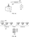
- the gNodeB 210 includes a plurality of antennas which form an antenna array and using known techniques the signal transmitted from the gNodeB can be formed into a beam 320.
- the beam 320 transmits a synchronisation signal block 322 for detection by the UE 104.
- the synchronisation signal block 322 includes primary and secondary synchronisation signals as well as broadcast system information carried in a physical broadcast channel (PBCH).
- PBCH physical broadcast channel
- any waking UE accessing the NR network it is expected that it would detect the primary and secondary synchronisation signals (PSS and SSS) to gain time, frequency and frame synchronisation as well as sector, group and cell identity information.
- PSS and SSS primary and secondary synchronisation signals
- the use of multiple antennas both at the UE and gNodeB further allows the use of beam forming to improve the spectral efficiency or traffic density which can be supported by the wireless communications system.
- the requirement for UEs to be able to synchronise to each of these beams separately means that the gNodeB can transmit separate synchronisation signals and one or more PBCH OFDM symbols for each beam that it forms.
- This separation of the synchronisation signals can lead in some examples to the concept of a synchronisation signal block or burst comprised of the PSS, SSS and PBCH (where a synchronisation signal block is typically applied to a single beam).
- a synchronisation signal burst is comprised of multiple synchronisation signal blocks, where each synchronisation signal block within the synchronisation signal burst can be applied to a different beam.
- a synchronisation signal burst set is then comprised of multiple synchronisation signal bursts. Synchronisation signal blocks for a particular beam can be combined by the UE between synchronisation signal bursts within the synchronisation signal burst set.
- the synchronisation signal burst set is repeated at regular intervals for use by new UEs entering the network and for enabling the UEs to perform down-link cell measurements and other procedures.
- An example is shown in Figure 3b , where there are three synchronisation signal blocks 304 (each comprised of the PSS 306, SSS 308 and PBCH 310) in a synchronisation signal burst 302 as shown, i.e. three different beams for each synchronisation signal burst.
- the synchronisation signal burst set 301 has thee synchronisation signal bursts 302 and the synchronisation signal burst set 301 is repeated.
- the UE can then find and decode the physical broadcast channel (PBCH) which in turn provides the UE with critical system and configuration information of the particular component carrier and/or beam.
- PBCH physical broadcast channel
- MIB Master Information Block
- MIB System Information Block
- the detection of the PSS and SSS entails the processing of signals to detect the particular sequences used in their construction, without need for channel estimation and equalisation.
- the decoding of the PBCH requires channel estimation and equalisation prior to demodulation and error decoding (for example, performing decoding of a forward error correction code, such as a polar code or a tail biting convolutional code) of critical system information bits carried by the PBCH.
- Channel estimation requires the transmission of reference symbols that can be used to estimate the channel transfer function. Since reference symbols do not carry any information, it can be argued that their use reduces spectral efficiency. It is therefore desirable to reduce the number or density of reference symbols so as to minimise the loss in spectral efficiency arising from their inclusion.
- Co-pending European patent applicant number EP17169834.3 [4] which is applicable to embodiments of the present technique, provides an arrangement in which a wireless communications device operating within a wireless communications network can more efficiently detect information from a control channel such as a physical broadcast channel which is transmitted as one or more OFDM symbols preceded by a synchronisation OFDM symbol which is initially detected by a communications device or UE when the UE initially attempts to access the wireless communications network.
- a control channel such as a physical broadcast channel which is transmitted as one or more OFDM symbols preceded by a synchronisation OFDM symbol which is initially detected by a communications device or UE when the UE initially attempts to access the wireless communications network.
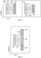
- Embodiments co-pending European patent applicant number EP17169834.3 can provide an arrangement in which the demodulation reference symbols (DMRS) which are used to estimate a channel transfer function or channel impulse response are transmitted in the PBCH OFDM symbols, wherein the PBCH OFDM symbols either do not have demodulation reference symbols in sub carrier signals in a frequency range which overlaps those of the synchronisation OFDM symbol or has a different pattern of reference symbols in this overlapping region compared to a region which does not overlap the frequencies of the synchronisation OFDM symbol.
- DMRS demodulation reference symbols
Landscapes
- Engineering & Computer Science (AREA)
- Signal Processing (AREA)
- Computer Networks & Wireless Communication (AREA)
- Databases & Information Systems (AREA)
- Mobile Radio Communication Systems (AREA)
Claims (15)
- Dispositif de communications sans fil (104) permettant de transmettre ou de recevoir des données par l'intermédiaire d'un réseau de communications sans fil, le dispositif de communications sans fil comprenantun système de circuits transmetteur configuré pour transmettre des signaux radio par l'intermédiaire d'une interface d'accès sans fil à un équipement d'infrastructure formant une partie de réseau radio du réseau de communications sans fil,un système de circuits récepteur configuré pour recevoir des signaux radio transmis à partir de l'équipement d'infrastructure par l'intermédiaire de l'interface d'accès sans fil, etun système de circuits de commande configuré pour commander le système de circuits transmetteur et le système de circuits récepteur pour transmettre des données transportées par les signaux radio à l'équipement d'infrastructure et recevoir des données transportées par les signaux radio en provenance de l'équipement d'infrastructure, le système de circuits de commande étant configuré avec le système de circuits récepteurpour détecter une pluralité de blocs de signal de synchronisation (304, 322) transmis par l'équipement d'infrastructure (101, 210) par l'intermédiaire de l'interface d'accès sans fil, chaque bloc de signal de synchronisation (304, 322) comprenant un ou plusieurs premiers symboles de multiplexage par répartition orthogonale de la fréquence, OFDM, transportant un signal de synchronisation primaire (306), un ou plusieurs deuxièmes symboles OFDM transportant un signal de synchronisation secondaire (308) et un ou plusieurs troisièmes symboles OFDM transportant des informations d'un canal de diffusion physique (310) de l'interface d'accès sans fil, chacun des symboles OFDM du bloc de synchronisation étant formé par une pluralité de signaux de sous-porteuse de domaine fréquentiel étant chacun transmis sur la durée du symbole OFDM en tant qu'élément de ressource de l'interface d'accès sans fil, chaque symbole OFDM du bloc de signal de synchronisation ayant le même espacement de sous-porteuses, et chacun des troisièmes symboles OFDM étant agencé pour comporter des symboles de référence de démodulation, chaque bloc de signal de synchronisation (304, 322) étant transmis par le biais d'un faisceau d'une pluralité de faisceaux (320), chaque faisceau (320) étant formé à l'aide d'une pluralité d'antennes, et un vecteur de poids d'antenne utilisé pour former chaque faisceau (320) est le même pour les premiers symboles OFDM, les deuxièmes symboles OFDM et les troisièmes symboles OFDM,pour décoder chacun des blocs de signal de synchronisation détectés pour récupérer un indice temporel de bloc de signal de synchronisation représentant un nombre cardinal du bloc de signal de synchronisation détecté, chaque nombre cardinal étant associé à un faisceau de la pluralité de faisceaux utilisé pour transmettre les blocs de signal de synchronisation (304, 322) détectés, etpour déterminer, en fonction de l'indice temporel de bloc de signal de synchronisation récupéré, celui des faisceaux (320) qui a été utilisé pour transmettre chacun des blocs de signal de synchronisation détectés (304, 322) précité, dans lequel un ou plusieurs bits les moins significatifs de l'indice temporel de bloc de signal de synchronisation sont indiqués par un ordre relatif au sein du bloc de signal de synchronisation détecté (304, 322) des premiers symboles OFDM et des deuxièmes symboles OFDM.
- Dispositif de communications sans fil (104) selon la revendication 1, dans lequel chacun des blocs de signal de synchronisation (304, 322) a l'une parmi une pluralité de compositions uniques de positions relatives au sein de chacun des blocs de signal de synchronisation (304, 322) précité des premiers symboles OFDM, des deuxièmes symboles OFDM et des troisièmes symboles OFDM.
- Dispositif de communications sans fil (104) selon la revendication 2, dans lequel une première des compositions indique un indice temporel de bloc de signal de synchronisation représentant des blocs de signal de synchronisation (304, 322) avec des nombres cardinaux impairs, et une seconde des compositions indique un indice temporel de bloc de signal de synchronisation représentant des blocs de signal de synchronisation (304, 322) avec des nombres cardinaux pairs.
- Dispositif de communications sans fil (104) selon la revendication 2, dans lequel une première des compositions indique des indices temporels de bloc de signal de synchronisation représentant des blocs de signal de synchronisation (304, 322) avec un nombre cardinal faisant partie d'une première plage prédéterminée, et une seconde des compositions indique des indices temporels de bloc de signal de synchronisation représentant des blocs de signal de synchronisation (304, 322) avec un nombre cardinal faisant partie d'une seconde plage prédéterminée, la première plage prédéterminée étant distincte de la seconde plage prédéterminée.
- Dispositif de communications sans fil (104) selon la revendication 4, dans lequel un bit le plus significatif des indices temporels de bloc de signal de synchronisation représentant les blocs de signal de synchronisation (304, 322) avec un nombre cardinal faisant partie de la première plage prédéterminée est différent d'un bit le plus significatif des indices temporels de bloc de signal de synchronisation représentant les blocs de signal de synchronisation (304, 322) avec un nombre cardinal faisant partie de la seconde plage prédéterminée.
- Dispositif de communications sans fil (104) selon la revendication 1, configuré pour démoduler les symboles de référence de démodulation à l'aide d'une séquence dérivée de l'indice temporel de bloc de signal de synchronisation récupéré.
- Dispositif de communications sans fil (104) selon la revendication 1, configuré pour démoduler des données utiles transportées par le canal de diffusion physique (310), les données utiles ayant été modulées à l'aide d'une diversité spatiale de signal par l'équipement d'infrastructure.
- Procédé de fonctionnement d'un dispositif de communications sans fil (104) permettant de transmettre ou de recevoir des données par l'intermédiaire d'un réseau de communications sans fil, le procédé comprenantla détection d'une pluralité de blocs de signal de synchronisation transmis par un équipement d'infrastructure faisant partie d'une partie de réseau radio du réseau de communications sans fil par l'intermédiaire d'une interface d'accès sans fil, chaque bloc de signal de synchronisation comprenant un ou plusieurs premiers symboles de multiplexage par répartition orthogonale de la fréquence, OFDM, transportant un signal de synchronisation primaire, un ou plusieurs deuxièmes symboles OFDM transportant un signal de synchronisation secondaire et un ou plusieurs troisièmes symboles OFDM transportant des informations d'un canal de diffusion physique de l'interface d'accès sans fil, chacun des symboles OFDM du bloc de synchronisation étant formé par une pluralité de signaux de sous-porteuse de domaine fréquentiel étant transmis sur la durée du symbole OFDM en tant qu'élément de ressource de l'interface d'accès sans fil, chaque symbole OFDM du bloc de signal de synchronisation ayant le même espacement de sous-porteuses, et chacun des troisièmes symboles OFDM étant agencé pour comporter des symboles de référence de démodulation, chaque bloc de signal de synchronisation étant transmis par le biais d'un faisceau d'une pluralité de faisceaux, chaque faisceau étant formé à l'aide d'une pluralité d'antennes, et un vecteur de poids d'antenne utilisé pour former chaque faisceau est le même pour les premiers symboles OFDM, les deuxièmes symboles OFDM et les troisièmes symboles OFDM,le décodage de chacun des blocs de signal de synchronisation détectés pour récupérer un indice temporel de bloc de signal de synchronisation représentant un nombre cardinal du bloc de signal de synchronisation détecté, chaque nombre cardinal étant associé à un faisceau de la pluralité de faisceaux utilisé pour transmettre les blocs de signal de synchronisation détectés, etla détermination, en fonction de l'indice temporel de bloc de signal de synchronisation récupéré, de celui des faisceaux qui a été utilisé pour transmettre chacun des blocs de signal de synchronisation détectés précité, dans lequel un ou plusieurs bits les moins significatifs de l'indice temporel de bloc de signal de synchronisation sont indiqués par un ordre relatif au sein du bloc de signal de synchronisation détecté des premiers symboles OFDM et des deuxièmes symboles OFDM.
- Procédé selon la revendication 8, dans lequel chacun des blocs de signal de synchronisation a l'une parmi une pluralité de compositions uniques de positions relatives au sein de chacun des blocs de signal de synchronisation précité des premiers symboles OFDM, des deuxièmes symboles OFDM et des troisièmes symboles OFDM.
- Équipement d'infrastructure (101, 210) destiné à faire partie d'une partie de réseau radio d'un réseau de communications sans fil, l'équipement d'infrastructure (101, 210) comprenantun système de circuits transmetteur configuré pour transmettre des signaux radio par l'intermédiaire d'une interface d'accès sans fil formée par l'équipement d'infrastructure à un ou plusieurs dispositifs de communication sans fil,un système de circuits récepteur configuré pour recevoir des signaux radio transmis à partir du ou des dispositifs de communications sans fil par l'intermédiaire de l'interface d'accès sans fil, etun système de circuits de commande configuré pour commander le système de circuits transmetteur et le système de circuits récepteur pour transmettre des données transportées par les signaux radio au ou aux dispositifs de communication sans fil et pour recevoir des données transportées par les signaux radio en provenance du ou des dispositifs de communication sans fil, le système de circuits de commande étant configuré avec le système de circuits récepteurpour former une pluralité de blocs de signal de synchronisation comprenant chacun un ou plusieurs premiers symboles de multiplexage par répartition orthogonale de la fréquence, OFDM, transportant un signal de synchronisation primaire, un ou plusieurs deuxièmes symboles OFDM transportant un signal de synchronisation secondaire et un ou plusieurs troisièmes symboles OFDM transportant des informations d'un canal de diffusion physique de l'interface d'accès sans fil, chacun des symboles OFDM du bloc de synchronisation étant formé par une pluralité de signaux de sous-porteuse de domaine fréquentiel étant transmis sur la durée du symbole OFDM en tant qu'élément de ressource de l'interface d'accès sans fil, chaque symbole OFDM du bloc de signal de synchronisation ayant le même espacement de sous-porteuses, et chacun des troisièmes symboles OFDM étant agencé pour comporter des symboles de référence de démodulation, chaque bloc de signal de synchronisation étant transmis par le biais d'un faisceau d'une pluralité de faisceaux, chaque faisceau étant formé à l'aide d'une pluralité d'antennes, et un vecteur de poids d'antenne utilisé pour former chaque faisceau est le même pour les premiers symboles OFDM, les deuxièmes symboles OFDM et les troisièmes symboles OFDM, etpour transmettre les blocs de signal de synchronisation au ou aux dispositifs de communication sans fil permettant de recevoir les informations de diffusion fournies par le canal de diffusion physique,dans lequel chacun des blocs de signal de synchronisation comprend une indication d'un indice temporel de bloc de signal de synchronisation représentant un nombre cardinal de chacun des blocs de signal de synchronisation précité, chaque nombre cardinal étant associé à un faisceau de la pluralité de faisceaux utilisé pour transmettre chacun des blocs de signal de synchronisation précité, etun ou plusieurs bits les moins significatifs de l'indice temporel de bloc de signal de synchronisation sont indiqués par un ordre relatif au sein du bloc de signal de synchronisation détecté des premiers symboles OFDM et des deuxièmes symboles OFDM.
- Équipement d'infrastructure (101, 210) selon la revendication 10, dans lequel chacun des blocs de signal de synchronisation a l'une parmi une pluralité de compositions uniques de positions relatives au sein de chacun des blocs de signal de synchronisation précité des premiers symboles OFDM, des deuxièmes symboles OFDM et des troisièmes symboles OFDM.
- Équipement d'infrastructure (101, 210) selon la revendication 11, dans lequel une première des compositions indique des indices temporels de bloc de signal de synchronisation représentant des blocs de signal de synchronisation avec un nombre cardinal faisant partie d'une première plage prédéterminée, et une seconde des compositions indique des indices temporels de bloc de signal de synchronisation représentant des blocs de signal de synchronisation avec un nombre cardinal faisant partie d'une seconde plage prédéterminée, la première plage prédéterminée étant distincte de la seconde plage prédéterminée.
- Équipement d'infrastructure (101, 210) selon la revendication 12, dans lequel un bit le plus significatif des indices temporels de bloc de signal de synchronisation représentant les blocs de signal de synchronisation avec un nombre cardinal faisant partie de la première plage prédéterminée est différent d'un bit le plus significatif des indices temporels de bloc de signal de synchronisation représentant les blocs de signal de synchronisation avec un nombre cardinal faisant partie de la seconde plage prédéterminée.
- Procédé de fonctionnement d'un équipement d'infrastructure (101, 210) destiné à faire partie d'une partie de réseau radio d'un réseau de communications sans fil, le procédé comprenantla formation d'une pluralité de blocs de signal de synchronisation comprenant chacun un ou plusieurs premiers symboles de multiplexage par répartition orthogonale de la fréquence, OFDM, transportant un signal de synchronisation primaire, un ou plusieurs deuxièmes symboles OFDM transportant un signal de synchronisation secondaire et un ou plusieurs troisièmes symboles OFDM transportant des informations d'un canal de diffusion physique d'une interface d'accès sans fil formée par l'équipement d'infrastructure, chacun des symboles OFDM du bloc de synchronisation étant formé par une pluralité de signaux de sous-porteuse de domaine fréquentiel étant chacun transmis sur la durée du symbole OFDM en tant qu'élément de ressource de l'interface d'accès sans fil, chaque symbole OFDM du bloc de signal de synchronisation ayant le même espacement de sous-porteuses, et chacun des troisièmes symboles OFDM étant agencé pour comporter des symboles de référence de démodulation, chaque bloc de signal de synchronisation étant transmis par le biais d'un faisceau d'une pluralité de faisceaux, chaque faisceau étant formé à l'aide d'une pluralité d'antennes, et un vecteur de poids d'antenne utilisé pour former chaque faisceau est le même pour les premiers symboles OFDM, les deuxièmes symboles OFDM et les troisièmes symboles OFDM, etla transmission des blocs de signal de synchronisation à un ou plusieurs dispositifs de communication sans fil permettant de recevoir les informations de diffusion fournies par le canal de diffusion physique,dans lequel chacun des blocs de signal de synchronisation comprend une indication d'un indice temporel de bloc de signal de synchronisation représentant un nombre cardinal de chacun des blocs de signal de synchronisation précité, chaque nombre cardinal étant associé à un faisceau de la pluralité de faisceaux utilisé pour transmettre chacun des blocs de signal de synchronisation précité, etun ou plusieurs bits les moins significatifs de l'indice temporel de bloc de signal de synchronisation sont indiqués par un ordre relatif au sein du bloc de signal de synchronisation détecté des premiers symboles OFDM et des deuxièmes symboles OFDM.
- Procédé selon la revendication 14, comprenant
la modulation de données utiles transportées par le canal de diffusion physique à l'aide d'une diversité spatiale de signal.
Applications Claiming Priority (2)
| Application Number | Priority Date | Filing Date | Title |
|---|---|---|---|
| EP17176479 | 2017-06-16 | ||
| PCT/EP2018/063683 WO2018228789A1 (fr) | 2017-06-16 | 2018-05-24 | Dispositif de communication sans fil, équipement d'infrastructure et méthodes |
Publications (2)
| Publication Number | Publication Date |
|---|---|
| EP3635888A1 EP3635888A1 (fr) | 2020-04-15 |
| EP3635888B1 true EP3635888B1 (fr) | 2025-07-09 |
Family
ID=59077916
Family Applications (1)
| Application Number | Title | Priority Date | Filing Date |
|---|---|---|---|
| EP18728560.6A Active EP3635888B1 (fr) | 2017-06-16 | 2018-05-24 | Dispositif de communication sans fil, équipement d'infrastructure et méthodes |
Country Status (4)
| Country | Link |
|---|---|
| US (2) | US11303494B2 (fr) |
| EP (1) | EP3635888B1 (fr) |
| CN (1) | CN110754051B (fr) |
| WO (1) | WO2018228789A1 (fr) |
Families Citing this family (17)
| Publication number | Priority date | Publication date | Assignee | Title |
|---|---|---|---|---|
| WO2018142978A1 (fr) * | 2017-02-03 | 2018-08-09 | 株式会社Nttドコモ | Station de base et procédé de transmission de signal de synchronisation |
| EP4009719B1 (fr) * | 2017-05-03 | 2023-01-25 | Sony Group Corporation | Utilisation efficace de ssbs dans de nouveaux systèmes radio |
| WO2019127495A1 (fr) * | 2017-12-29 | 2019-07-04 | Oppo广东移动通信有限公司 | Procédé d'émission de signal, dispositif terminal et dispositif réseau |
| CN110611948B (zh) * | 2018-06-14 | 2021-01-08 | 维沃移动通信有限公司 | 同步信号块的传输方法、网络设备及终端 |
| CN113225796A (zh) * | 2018-12-24 | 2021-08-06 | 华为技术有限公司 | 功率控制方法及装置 |
| KR20200101045A (ko) * | 2019-02-19 | 2020-08-27 | 삼성전자주식회사 | 무선 통신 시스템에서 동기 신호 송수신 방법 및 장치 |
| CN111726821B (zh) * | 2019-03-21 | 2022-04-26 | 华为技术有限公司 | 一种通信方法及设备 |
| CN113661757B (zh) | 2019-03-29 | 2025-08-08 | 三星电子株式会社 | 用于为毫米无线通信执行信道复用的方法和装置 |
| WO2020204543A1 (fr) * | 2019-03-29 | 2020-10-08 | Samsung Electronics Co., Ltd. | Procédé et appareil pour réaliser un multiplexage de canal pour une communication sans fil millimétrique |
| US11178628B2 (en) * | 2019-10-31 | 2021-11-16 | National Instruments Corporation | Efficient beam sweeping at a mobile device receiver |
| CN111953627B (zh) * | 2020-08-11 | 2022-11-11 | Oppo广东移动通信有限公司 | 检测ssb序号的方法及装置 |
| CN111934826B (zh) * | 2020-10-12 | 2020-12-25 | 翱捷科技股份有限公司 | 一种lte或lte-m跨周期合并接收pbch的方法及系统 |
| EP4226686A4 (fr) * | 2020-10-15 | 2023-12-27 | Apple Inc. | Transmission redondante pour systèmes radio à large bande |
| WO2022078830A1 (fr) * | 2020-10-16 | 2022-04-21 | Sony Group Corporation | Procédés d'attribution dynamique d'un ou plusieurs blocs de signaux de synchronisation, nœud de réseau associé et dispositif sans fil associé |
| CN117440480A (zh) * | 2022-07-14 | 2024-01-23 | 维沃移动通信有限公司 | 信息确定方法、装置及终端 |
| WO2025211469A1 (fr) * | 2024-04-01 | 2025-10-09 | 엘지전자 주식회사 | Procédé et appareil d'émission et de réception de signal dans un système de communication sans fil |
| WO2025222418A1 (fr) * | 2024-04-24 | 2025-10-30 | Mediatek Singapore Pte. Ltd. | Schémas de recherche de cellule initiale |
Citations (1)
| Publication number | Priority date | Publication date | Assignee | Title |
|---|---|---|---|---|
| WO2017076317A1 (fr) * | 2015-11-05 | 2017-05-11 | 夏普株式会社 | Procédé de configuration d'un canal physique, station de base et équipement d'utilisateur |
Family Cites Families (17)
| Publication number | Priority date | Publication date | Assignee | Title |
|---|---|---|---|---|
| SG11201602473SA (en) | 2013-11-27 | 2016-04-28 | Ericsson Telefon Ab L M | Network node, wireless device, methods therein, for sending and detecting, respectively, synchronization signal and an associated information |
| KR101901949B1 (ko) | 2014-08-26 | 2018-09-28 | 엘지전자 주식회사 | 무선 통신 시스템에서 동기 신호를 송수신하는 방법 및 이를 수행하는 장치 |
| GB2532233A (en) | 2014-11-12 | 2016-05-18 | Sony Corp | Transmitter and receiver and methods of transmitting and receiving |
| WO2018008916A2 (fr) * | 2016-07-02 | 2018-01-11 | 엘지전자 주식회사 | Procédé de réception de signaux en liaison descendante et équipement utilisateur, ainsi que procédé d'émission de signaux en liaison descendante et station de base |
| US10523354B2 (en) * | 2017-02-24 | 2019-12-31 | Samsung Electronics Co., Ltd. | Method and apparatus for design of NR-SS burst set |
| US11044650B2 (en) * | 2017-03-23 | 2021-06-22 | Convida Wireless, Llc | Downlink measurement design in new radio |
| BR112019022709B1 (pt) * | 2017-05-04 | 2023-11-07 | Sharp Kabushiki Kaisha | Equipamento de usuário, método em um equipamento de usuário, aparelho de estação-base e método de um aparelho de estação-base |
| US10512051B2 (en) * | 2017-05-04 | 2019-12-17 | Qualcomm Incorporated | Unified synchronization design under mixed deployments |
| CN110249666A (zh) * | 2017-05-05 | 2019-09-17 | 富士通株式会社 | 时间索引指示方法、定时获取方法及其装置、通信系统 |
| FI3602937T3 (fi) | 2017-05-05 | 2024-11-19 | Sony Group Corp | Viestintälaite, infrastruktuurilaitteisto ja menetelmiä |
| CN110603853B (zh) * | 2017-05-05 | 2020-11-27 | 中兴通讯股份有限公司 | 用于传送同步信号定时信息的技术 |
| EP3634040B1 (fr) * | 2017-06-02 | 2024-10-02 | NTT DoCoMo, Inc. | Terminal utilisateur et procédé de communication sans fil |
| WO2018229952A1 (fr) * | 2017-06-15 | 2018-12-20 | 株式会社Nttドコモ | Équipement utilisateur et procédé de communication sans fil |
| MX2019014881A (es) * | 2017-06-15 | 2020-02-13 | Sharp Kk | Metodo y aparato para generar y usar una se?al de referencia para canal de difusion para un sistema de radio. |
| US10834575B2 (en) * | 2017-06-16 | 2020-11-10 | At&T Intellectual Property I, L.P. | Initial access configuration for coexistence of multiple wireless communication systems |
| US11070262B2 (en) * | 2018-03-19 | 2021-07-20 | Qualcomm Incorporated | Range extension for communication systems |
| US10686585B2 (en) * | 2018-08-31 | 2020-06-16 | Apple Inc. | Methods and devices for broadcast channel decoding |
-
2018
- 2018-05-24 CN CN201880039769.0A patent/CN110754051B/zh active Active
- 2018-05-24 WO PCT/EP2018/063683 patent/WO2018228789A1/fr not_active Ceased
- 2018-05-24 EP EP18728560.6A patent/EP3635888B1/fr active Active
- 2018-05-24 US US16/620,871 patent/US11303494B2/en active Active
-
2022
- 2022-03-01 US US17/683,359 patent/US20220191080A1/en active Pending
Patent Citations (1)
| Publication number | Priority date | Publication date | Assignee | Title |
|---|---|---|---|---|
| WO2017076317A1 (fr) * | 2015-11-05 | 2017-05-11 | 夏普株式会社 | Procédé de configuration d'un canal physique, station de base et équipement d'utilisateur |
Non-Patent Citations (1)
| Title |
|---|
| HUAWEI ET AL: "Discussion on SS block time index indication", vol. RAN WG1, no. Hangzhou, China; 20170515 - 20170519, 14 May 2017 (2017-05-14), XP051273362, Retrieved from the Internet <URL:http://www.3gpp.org/ftp/Meetings_3GPP_SYNC/RAN1/Docs/> [retrieved on 20170514] * |
Also Published As
| Publication number | Publication date |
|---|---|
| WO2018228789A1 (fr) | 2018-12-20 |
| CN110754051A (zh) | 2020-02-04 |
| CN110754051B (zh) | 2022-04-22 |
| US20220191080A1 (en) | 2022-06-16 |
| US20200204423A1 (en) | 2020-06-25 |
| US11303494B2 (en) | 2022-04-12 |
| EP3635888A1 (fr) | 2020-04-15 |
Similar Documents
| Publication | Publication Date | Title |
|---|---|---|
| US20220191080A1 (en) | Wireless communications device, infrastructure equipment and methods | |
| EP3602937B1 (fr) | Dispositif de communications, équipement d'infrastructure et procédés | |
| TWI763784B (zh) | 同步信號塊 | |
| US11128510B2 (en) | Data transmission method, user equipment, and network side device | |
| CN110720178B (zh) | 用于广播信道的同步信号 | |
| KR20190033557A (ko) | 차량-대-차량 통신을 위한 복조 참조 신호 설계 | |
| US8483161B2 (en) | System information transmission method and subframe structure | |
| EP4236080B1 (fr) | Codage et décodage à faible latence de codes polaires à bits inversés | |
| US20180063849A1 (en) | Transmission and detection methods for range extension | |
| EP2041887A1 (fr) | Activation d'antennes commutées mobiles | |
| US20240267272A1 (en) | Multiple symbol shift configuration | |
| JP2009515455A (ja) | セルラ通信システムにおいて通信装置に信号を伝送する方法及びシステム | |
| CN110463314A (zh) | 用于通信系统的广播信道配置和广播信道传输和接收的方法和装置 | |
| CN121605615A (zh) | 增强型ofdm传输 | |
| HK40014140A (en) | Method and apparatus for wireless communication | |
| HK40014140B (en) | Method and apparatus for wireless communication | |
| HK40019884A (en) | Synchronization signal for a broadcast channel |
Legal Events
| Date | Code | Title | Description |
|---|---|---|---|
| STAA | Information on the status of an ep patent application or granted ep patent |
Free format text: STATUS: UNKNOWN |
|
| STAA | Information on the status of an ep patent application or granted ep patent |
Free format text: STATUS: THE INTERNATIONAL PUBLICATION HAS BEEN MADE |
|
| PUAI | Public reference made under article 153(3) epc to a published international application that has entered the european phase |
Free format text: ORIGINAL CODE: 0009012 |
|
| STAA | Information on the status of an ep patent application or granted ep patent |
Free format text: STATUS: REQUEST FOR EXAMINATION WAS MADE |
|
| 17P | Request for examination filed |
Effective date: 20191203 |
|
| AK | Designated contracting states |
Kind code of ref document: A1 Designated state(s): AL AT BE BG CH CY CZ DE DK EE ES FI FR GB GR HR HU IE IS IT LI LT LU LV MC MK MT NL NO PL PT RO RS SE SI SK SM TR |
|
| AX | Request for extension of the european patent |
Extension state: BA ME |
|
| DAV | Request for validation of the european patent (deleted) | ||
| DAX | Request for extension of the european patent (deleted) | ||
| STAA | Information on the status of an ep patent application or granted ep patent |
Free format text: STATUS: EXAMINATION IS IN PROGRESS |
|
| 17Q | First examination report despatched |
Effective date: 20210504 |
|
| RAP3 | Party data changed (applicant data changed or rights of an application transferred) |
Owner name: SONY GROUP CORPORATION Owner name: SONY EUROPE LIMITED |
|
| GRAP | Despatch of communication of intention to grant a patent |
Free format text: ORIGINAL CODE: EPIDOSNIGR1 |
|
| STAA | Information on the status of an ep patent application or granted ep patent |
Free format text: STATUS: GRANT OF PATENT IS INTENDED |
|
| INTG | Intention to grant announced |
Effective date: 20250212 |
|
| GRAS | Grant fee paid |
Free format text: ORIGINAL CODE: EPIDOSNIGR3 |
|
| GRAA | (expected) grant |
Free format text: ORIGINAL CODE: 0009210 |
|
| STAA | Information on the status of an ep patent application or granted ep patent |
Free format text: STATUS: THE PATENT HAS BEEN GRANTED |
|
| P01 | Opt-out of the competence of the unified patent court (upc) registered |
Free format text: CASE NUMBER: APP_24090/2025 Effective date: 20250520 |
|
| AK | Designated contracting states |
Kind code of ref document: B1 Designated state(s): AL AT BE BG CH CY CZ DE DK EE ES FI FR GB GR HR HU IE IS IT LI LT LU LV MC MK MT NL NO PL PT RO RS SE SI SK SM TR |
|
| REG | Reference to a national code |
Ref country code: GB Ref legal event code: FG4D |
|
| REG | Reference to a national code |
Ref country code: CH Ref legal event code: EP |
|
| REG | Reference to a national code |
Ref country code: IE Ref legal event code: FG4D |
|
| REG | Reference to a national code |
Ref country code: DE Ref legal event code: R096 Ref document number: 602018083400 Country of ref document: DE |
|
| REG | Reference to a national code |
Ref country code: NL Ref legal event code: MP Effective date: 20250709 |
|
| PG25 | Lapsed in a contracting state [announced via postgrant information from national office to epo] |
Ref country code: PT Free format text: LAPSE BECAUSE OF FAILURE TO SUBMIT A TRANSLATION OF THE DESCRIPTION OR TO PAY THE FEE WITHIN THE PRESCRIBED TIME-LIMIT Effective date: 20251110 |
|
| PG25 | Lapsed in a contracting state [announced via postgrant information from national office to epo] |
Ref country code: NL Free format text: LAPSE BECAUSE OF FAILURE TO SUBMIT A TRANSLATION OF THE DESCRIPTION OR TO PAY THE FEE WITHIN THE PRESCRIBED TIME-LIMIT Effective date: 20250709 |
|
| REG | Reference to a national code |
Ref country code: AT Ref legal event code: MK05 Ref document number: 1812872 Country of ref document: AT Kind code of ref document: T Effective date: 20250709 |
|
| PG25 | Lapsed in a contracting state [announced via postgrant information from national office to epo] |
Ref country code: IS Free format text: LAPSE BECAUSE OF FAILURE TO SUBMIT A TRANSLATION OF THE DESCRIPTION OR TO PAY THE FEE WITHIN THE PRESCRIBED TIME-LIMIT Effective date: 20251109 |
|
| PG25 | Lapsed in a contracting state [announced via postgrant information from national office to epo] |
Ref country code: NO Free format text: LAPSE BECAUSE OF FAILURE TO SUBMIT A TRANSLATION OF THE DESCRIPTION OR TO PAY THE FEE WITHIN THE PRESCRIBED TIME-LIMIT Effective date: 20251009 |
|
| REG | Reference to a national code |
Ref country code: LT Ref legal event code: MG9D |
|
| PG25 | Lapsed in a contracting state [announced via postgrant information from national office to epo] |
Ref country code: AT Free format text: LAPSE BECAUSE OF FAILURE TO SUBMIT A TRANSLATION OF THE DESCRIPTION OR TO PAY THE FEE WITHIN THE PRESCRIBED TIME-LIMIT Effective date: 20250709 |
|
| PG25 | Lapsed in a contracting state [announced via postgrant information from national office to epo] |
Ref country code: FI Free format text: LAPSE BECAUSE OF FAILURE TO SUBMIT A TRANSLATION OF THE DESCRIPTION OR TO PAY THE FEE WITHIN THE PRESCRIBED TIME-LIMIT Effective date: 20250709 |
|
| PG25 | Lapsed in a contracting state [announced via postgrant information from national office to epo] |
Ref country code: HR Free format text: LAPSE BECAUSE OF FAILURE TO SUBMIT A TRANSLATION OF THE DESCRIPTION OR TO PAY THE FEE WITHIN THE PRESCRIBED TIME-LIMIT Effective date: 20250709 |
|
| PG25 | Lapsed in a contracting state [announced via postgrant information from national office to epo] |
Ref country code: GR Free format text: LAPSE BECAUSE OF FAILURE TO SUBMIT A TRANSLATION OF THE DESCRIPTION OR TO PAY THE FEE WITHIN THE PRESCRIBED TIME-LIMIT Effective date: 20251010 |
|
| PG25 | Lapsed in a contracting state [announced via postgrant information from national office to epo] |
Ref country code: SE Free format text: LAPSE BECAUSE OF FAILURE TO SUBMIT A TRANSLATION OF THE DESCRIPTION OR TO PAY THE FEE WITHIN THE PRESCRIBED TIME-LIMIT Effective date: 20250709 |
|
| PG25 | Lapsed in a contracting state [announced via postgrant information from national office to epo] |
Ref country code: LV Free format text: LAPSE BECAUSE OF FAILURE TO SUBMIT A TRANSLATION OF THE DESCRIPTION OR TO PAY THE FEE WITHIN THE PRESCRIBED TIME-LIMIT Effective date: 20250709 |
|
| PG25 | Lapsed in a contracting state [announced via postgrant information from national office to epo] |
Ref country code: BG Free format text: LAPSE BECAUSE OF FAILURE TO SUBMIT A TRANSLATION OF THE DESCRIPTION OR TO PAY THE FEE WITHIN THE PRESCRIBED TIME-LIMIT Effective date: 20250709 Ref country code: PL Free format text: LAPSE BECAUSE OF FAILURE TO SUBMIT A TRANSLATION OF THE DESCRIPTION OR TO PAY THE FEE WITHIN THE PRESCRIBED TIME-LIMIT Effective date: 20250709 |
|
| PG25 | Lapsed in a contracting state [announced via postgrant information from national office to epo] |
Ref country code: RS Free format text: LAPSE BECAUSE OF FAILURE TO SUBMIT A TRANSLATION OF THE DESCRIPTION OR TO PAY THE FEE WITHIN THE PRESCRIBED TIME-LIMIT Effective date: 20251009 |
|
| PG25 | Lapsed in a contracting state [announced via postgrant information from national office to epo] |
Ref country code: ES Free format text: LAPSE BECAUSE OF FAILURE TO SUBMIT A TRANSLATION OF THE DESCRIPTION OR TO PAY THE FEE WITHIN THE PRESCRIBED TIME-LIMIT Effective date: 20250709 |
|
| PG25 | Lapsed in a contracting state [announced via postgrant information from national office to epo] |
Ref country code: SM Free format text: LAPSE BECAUSE OF FAILURE TO SUBMIT A TRANSLATION OF THE DESCRIPTION OR TO PAY THE FEE WITHIN THE PRESCRIBED TIME-LIMIT Effective date: 20250709 |
|
| PGFP | Annual fee paid to national office [announced via postgrant information from national office to epo] |
Ref country code: GB Payment date: 20260317 Year of fee payment: 9 |
|
| PG25 | Lapsed in a contracting state [announced via postgrant information from national office to epo] |
Ref country code: DK Free format text: LAPSE BECAUSE OF FAILURE TO SUBMIT A TRANSLATION OF THE DESCRIPTION OR TO PAY THE FEE WITHIN THE PRESCRIBED TIME-LIMIT Effective date: 20250709 |
|
| PG25 | Lapsed in a contracting state [announced via postgrant information from national office to epo] |
Ref country code: IT Free format text: LAPSE BECAUSE OF FAILURE TO SUBMIT A TRANSLATION OF THE DESCRIPTION OR TO PAY THE FEE WITHIN THE PRESCRIBED TIME-LIMIT Effective date: 20250709 |
|
| PG25 | Lapsed in a contracting state [announced via postgrant information from national office to epo] |
Ref country code: CZ Free format text: LAPSE BECAUSE OF FAILURE TO SUBMIT A TRANSLATION OF THE DESCRIPTION OR TO PAY THE FEE WITHIN THE PRESCRIBED TIME-LIMIT Effective date: 20250709 |
|
| PG25 | Lapsed in a contracting state [announced via postgrant information from national office to epo] |
Ref country code: EE Free format text: LAPSE BECAUSE OF FAILURE TO SUBMIT A TRANSLATION OF THE DESCRIPTION OR TO PAY THE FEE WITHIN THE PRESCRIBED TIME-LIMIT Effective date: 20250709 Ref country code: SK Free format text: LAPSE BECAUSE OF FAILURE TO SUBMIT A TRANSLATION OF THE DESCRIPTION OR TO PAY THE FEE WITHIN THE PRESCRIBED TIME-LIMIT Effective date: 20250709 |