EP3636400A1 - Modularer greifer für fahrzeug-karosserieteil - Google Patents
Modularer greifer für fahrzeug-karosserieteil Download PDFInfo
- Publication number
- EP3636400A1 EP3636400A1 EP19194123.6A EP19194123A EP3636400A1 EP 3636400 A1 EP3636400 A1 EP 3636400A1 EP 19194123 A EP19194123 A EP 19194123A EP 3636400 A1 EP3636400 A1 EP 3636400A1
- Authority
- EP
- European Patent Office
- Prior art keywords
- gripper
- tool holder
- fusible
- base
- support
- Prior art date
- Legal status (The legal status is an assumption and is not a legal conclusion. Google has not performed a legal analysis and makes no representation as to the accuracy of the status listed.)
- Granted
Links
Images
Classifications
-
- B—PERFORMING OPERATIONS; TRANSPORTING
- B25—HAND TOOLS; PORTABLE POWER-DRIVEN TOOLS; MANIPULATORS
- B25J—MANIPULATORS; CHAMBERS PROVIDED WITH MANIPULATION DEVICES
- B25J19/00—Accessories fitted to manipulators, e.g. for monitoring, for viewing; Safety devices combined with or specially adapted for use in connection with manipulators
- B25J19/06—Safety devices
- B25J19/063—Safety devices working only upon contact with an outside object
- B25J19/065—Mechanical fuse
-
- B—PERFORMING OPERATIONS; TRANSPORTING
- B25—HAND TOOLS; PORTABLE POWER-DRIVEN TOOLS; MANIPULATORS
- B25J—MANIPULATORS; CHAMBERS PROVIDED WITH MANIPULATION DEVICES
- B25J15/00—Gripping heads and other end effectors
- B25J15/0052—Gripping heads and other end effectors multiple gripper units or multiple end effectors
- B25J15/0061—Gripping heads and other end effectors multiple gripper units or multiple end effectors mounted on a modular gripping structure
Definitions
- the invention relates to the field of tools for transporting or handling bodywork elements intended, for example, to equip factories for the manufacture of motor vehicles.
- the invention relates to a modular gripping system for bodywork elements, such as door panels or body sides of a motor vehicle.
- the body parts are caused to be moved between different positions by manipulating robots.
- robots include an arm at the end of which is attached a gripping system, or gripper, configured to hold a part for its movement.
- Said grippers can, for example, comprise a support structure in the form of a tube extending in a main direction, on which are mounted various gripping tools positioned on either side of the support structure in a manner specific to the workpiece .
- This gripping system has been shown to be very effective in handling the bodywork elements.
- this gripping system Since its conception, this gripping system has been improved and in particular has been added a protection system for its components (beam, support means, gripping tools) in the event of an impact.
- at least one support part of a tool holder has been provided with a fuse zone showing reduced mechanical resistance.
- the tool holder breaks, which protects the rest of the system.
- the support part of the tool holder breaks at its fuse zone, its replacement causes production to stop. This is generally a long stop because this part, in addition to a fuse function, also has a function for adjusting the position of the tool it carries.
- the development of a new setting when replacing this part can sometimes take up to three-quarters of an hour, which does not allow internal objectives in terms of breakdown time to be met.
- a solution remains to be found to reduce the troubleshooting time while retaining a protective function of the gripper components by means of a fuse zone.
- the invention aims to overcome the drawbacks of the prior art by proposing a new gripping system configured to provide a protection function by fuse zone without affecting the adjustment of the tool holder (s).
- the invention relates to a gripper comprising at least one structural beam, at least one gripping tool and at least one means for supporting a gripping tool, said supporting means comprising an arm at the end of which is mounted a tool holder, the arm comprising a base for fixing to a structural beam and a support part for the tool holder, the gripper being remarkable in that the arm further comprises a fusible part showing at least one zone of reduced mechanical resistance so as to rupture under the application of a force greater than a given threshold, said fusible part being arranged between the support part of the tool holder and the base.
- the invention consists in shifting the protection function by fuse zone to another part than the support part of the tool holder.
- the invention will dissociate the adjustment function from the protection fuse function so that there is no need to re-adjust the relative positions of the torque formed by the tool holder and its support part in arm breakage.
- Such a configuration makes it possible to significantly reduce repair times.
- the support part of the tool holder no longer shows a fuse zone, the latter is shown by an intermediate part designed for this purpose and which, preferably, does not show an adjustment function or else a simple adjustment in only one direction.
- the gripper further comprises an interface for attachment to a handling robot arm.
- Said fixing interface is preferably fixedly mounted on the structural beam (s).
- the gripper comprises at least two assemblies each provided with a gripping tool and a support means. Even more advantageously, the gripper comprises as many assemblies formed by a support means and a gripping tool as necessary.
- At least one fusible part is in the form of a connection sleeve configured to make the connection between the support part of the tool holder and the base or between the support part of the tool holder and a slide mounted on the 'base.
- the overall shape of the fusible part in the form of a tubular sleeve, makes it a simple component to produce and of moderate cost which has little effect on the overall cost of the gripper.
- At least one fusible part is a tubular part which has two ends and a shoulder along its length so that one of the ends shows a diameter greater than the diameter shown by the other end.
- the larger diameter end is intended to cooperate with the support part of the tool holder.
- At least one fusible part shows a zone of reduced mechanical resistance arranged at the base of the shoulder, that is to say on the part of the part of smaller diameter.
- the reduced resistance zone extends over the entire circumference of the smaller diameter end and is arranged at the base of the shoulder.
- the fusible element concentrates the maximum stresses whatever the level of force applied or the direction of the force applied to the various elements of the gripper.
- At least one fusible part is inserted by its end of smaller diameter in a hollow body presented by a base or in a hollow body formed by a slide.
- the fusible part is inserted into the hollow body until the end of the hollow body comes to stop against the external surface of the shoulder.
- the fitting diameter of the fusible part in the hollow body is the same as that shown by the anchoring foot of the support part of the tool holder.
- said fitting diameter is between 20 and 25 mm and, preferably, is 22 mm.
- a small connection radius increases the stress concentrations.
- At least one support part for the tool holder comprises an anchoring foot inserted in a fusible part; preferably, until the anchoring foot abuts against the internal surface of the shoulder.
- the abutment of the parts against the shoulder of the fuse part makes it possible to dispense with a step of adjusting the relative positioning of the parts and therefore to offer the possibility of a standardized and effortlessly repeatable positioning.
- the gripper is remarkable in that the zone of reduced mechanical resistance of at least one fusible part is a zone showing a reduced thickness compared to the thickness shown by the rest of the body. of said fuse part.
- At least one arm is a telescopic arm comprising a base and a slide mounted slidingly adjustable on said base.
- at least one arm is telescopic and comprises a base mounted on the beam, a slide and a sleeve, so that the slide is mounted adjustable in sliding on said base, and / or the sleeve is mounted adjustable in sliding on said slide.
- the support part of the tool holder comprises an anchoring foot showing a free end
- the gripper is remarkable in that the support part of the tool holder comprises a solid section anchoring foot and / or in that the support part of the tool holder comprises a ball joint for fixing the tool holder and the free end of the anchoring foot is disposed at least 8 cm from the center of the ball joint; preferably at least 10 cm.
- the position of the reduced resistance zone with respect to the load is more distant in the invention compared to the prior art, this makes the gripper more tolerant to the stresses generated by severe applications of shoeing processes and eliminates the unexpected breaks.
- the gripper is stronger while retaining a protective fuse function.
- the fusible part is made of an aluminum alloy of the 7075 type.
- This material is advantageous in that it is more brittle than the steel from which the support part of the tool holder is made. Also, when the elastic limit is reached, the fusible member will suddenly break without going through a phase of permanent deformation which is difficult to detect.
- the invention relates to a method of mounting a gripper according to the first aspect, the method being remarkable in that it comprises a step of mounting a support piece of a tool holder on a fusible element showing at least one zone of mechanical resistance reduced so as to break under the application of a force greater than a given threshold.
- the support part showing an anchoring foot and the fusible part being tubular said mounting step comprises fitting said anchoring foot into said fusible part.
- the support part is pressed into the fusible part until the anchoring foot comes to stop against the internal surface of the shoulder.
- the fixing is carried out by the installation of a pin after counter-drilling of the anchoring foot.
- the method further comprises a step of mounting a fusible part on a hollow body carried by the base or formed by a slide mounted on said base.
- the fusible part is pressed into the hollow body until the end of the hollow body abuts against the external surface of the shoulder.
- the fixing is carried out by the installation of a pin after counter-drilling of the fuse part.
- understand is synonymous with “include” and is not limiting as regards the presence of other elements in the gripper or of other steps in the process to which it relates. It is understood that the term “understand” includes the terms “consist of”. In the different figures, the same references designate identical or similar elements.
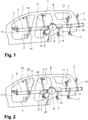
- the figure 1 having been commented on in the introductory part, we will now refer to the figure 2 illustrating a gripper 13 according to the invention.
- the method of mounting (or repairing) the gripper and the gripper as such will be described jointly.
- the gripper 13 comprises a general structure similar to that of the prior art with at least one structural beam 3, at least one tool 7 for gripping and at least one support means 11 for a tool 7 for gripping.
- the structural beam (s) 3 preferably consist of a steel profile which is, for example, in the form of a tube or a bar.
- the beam (s) 3 advantageously show a circular profile in order to facilitate the adjustment of the position of the arm (s) on the beam concerned.
- the gripper 13 may comprise a beam 3 of central structure, but it is conceivable that it comprises two parallel beams and integral with one another in particular by means of one or more spacers.
- a multi-beam architecture is advantageous for gripping heavy body parts.
- the structural beam (s) 3 are understood to be in a main direction and the support means (11) generally extend in a direction not parallel to said main direction, generally orthogonal thereto.
- the gripper 13 also comprises an interface 5 for attachment to a handling robot hand generally mounted in a fixed manner on the support beam (s) 3.
- the attachment interface 5 comprises a fixing plate and a device for fixing said plate to the support beam (s) 3.
- the fixing interface 5 is mounted in the central part of the support beam (s) 3.
- the gripper 13 will present in known manner at least one, preferably at least two and more preferably at least three gripping tools 7 designed for gripping a bodywork part 9.
- the gripping tools 7 include a means for clamping the bodywork part 9, in particular of the clamp type and / or at least one suction cup.
- the pliers may be of the mechanical type and be in the form of a collet with a clamping jaw. Optionally, they can be of the electromagnetic type.
- the tools can also include or be in the form of one or more holding suction cups. A person skilled in the art can envisage the use of other gripping tools.
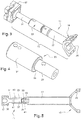
- Each gripping tool 7 is mounted on the beam by a support means 11 illustrated in figure 3 and comprising an arm 15 at the end of which is fixed a tool holder 17.
- the arm 15 comprises a base 19 for fixing to a structural beam (not shown in figure 3 ) and a support part 21 of the tool holder 17.
- the gripper according to the invention is remarkable in that the arm 15 further comprises a fusible part 23 showing at least one zone with a reduced mechanical resistance so as to break under the application of a force greater than a given threshold, said fuse part 23 being arranged between the support part 21 of the tool holder 17 and the base 19.
- the base 19 comprises a stirrup consisting of a semi-annular flange 25 and a semi-annular counter-flange (visible in figure 5 ) mounted tightly around the beam concerned, said stirrup being adjustable in sliding and rotation on said beam before tightening the counter-flange on the flange.
- the gripper therefore offers two first possibilities for adjusting the position of the gripping tool.
- the base 19 further comprises a tubular hollow body 27 projecting from the flange 25 and in which the fuse part 23 is mounted.
- the fuse part 23 can be mounted so that it can slide.
- a slide is mounted so that it can slide on the hollow body of said base.
- This architecture is advantageous in that it makes it possible to form a telescopic arm 15 adjustable in length.
- the adjustment is made by selecting a base 19 whose hollow body 27 shows an adequate length and the mounting of the part.
- fuse 23 is made in a standard position at the free end of said hollow body 27.
- the possibility of varying the length of the arm or arms 15 is a third possibility of adjusting the position of the gripping tool or tools 7.
- the position of the fuse piece 23 can be fixed by screwing, possibly with a pin for holding in position.
- the fuse piece 23 is configured to make the connection between the support piece 21 of the tool holder and the base 19 or between the support piece of the tool holder and a slide mounted on the base. It is a connecting piece which can be in the form of a bar.
- the fusible part 23 is a connecting part showing two ends (29, 31) and being in the form of a sleeve and therefore shows a hollow structure of tubular type.
- the fusible part 23 is placed on or in the hollow body 27 or slides by one of its ends 29 and collaborates with a support part 21 of the tool holder 17 by means of its other end 31.
- At least one fusible part is a tubular part having two ends (29, 31) and a shoulder 33 along its length so that one of the ends 31 shows a diameter greater than the diameter shown by l 'other end 29.
- the end 31 of larger diameter is intended to cooperate with the support part 21 of the tool holder.
- This configuration offers two advantages: on the one hand, it makes it possible to use a support piece 21 of the tool holder which includes an anchoring foot 37 of solid section, therefore more solid, which promotes rupture at the level of the fuse part 23 and not of the support part 21 of the tool holder. On the other hand, this makes it possible to use a support part 21 of the tool holder whose anchoring foot 37 has a larger diameter than in the prior art, therefore also more solid.
- At least one fusible part 23 shows an area 35 of reduced mechanical resistance (visible in figure 5 ) arranged at the base of the shoulder 33 on the part of the part of smaller diameter.
- the zone 35 of reduced mechanical resistance of at least one fusible part is a zone showing a reduced thickness compared to the thickness shown by the rest of the body of said fusible part 23.
- the thickness is understood to be the difference between the inside diameter and the outside diameter of said tube. This zone or section of reduced thickness can be obtained by machining the external surface of said tube.
- the fusible part 23 is a part showing no adjustment function so that its replacement is as rapid as possible, the adjustment functions being carried by d 'other rooms.
- the shoulder 33 shown by the fusible piece 23 plays a role since it allows positioning standard and repeatable of the fusible piece 23 relative to the base 19 or the slide on the one hand and / or relative to the support piece 21 of the tool holder.
- At least one fusible part 23 is inserted by its end 29 of smaller diameter in a hollow body 27 presented by a base 19 or in a hollow body formed by a slide.
- the fusible part 23 is inserted into the hollow body 27 until the end of the hollow body comes to abut against the external surface of the shoulder 33.
- the position of the support piece 21 is fixed, for example, by screwing at least one screw 43 (visible in figure 5 ) and by at least one additional pin 41.
- At least one support part for the tool holder comprises an anchoring foot inserted in a fusible part; preferably until the anchoring foot abuts against the internal surface of the shoulder.
- the position of the tool holder 17 on the arm 15 can be adjusted according to a fourth possibility of adjusting the position of the tool, namely by adjusting the rotation of the tool.
- the tool holder will advantageously include a ball joint 39 intended to cooperate with complementary means, such as a hemispherical cavity, carried by the tool holder 17.
- at least one support piece 21 of the tool holder comprises a ball joint 39 for fixing the tool holder 17 and the free end of the anchoring foot 37 is disposed at least 8 cm from the center of the ball joint 39; preferably at least 10 cm. This arrangement is advantageous by the leverage effect it provides.
- the reduced mechanical resistance zone 35 is in fact offset with respect to the center of the ball joint 39 with respect to the configuration known in the prior art, which makes it possible to lift larger masses. Indeed, in the prior art, the fusible area was at the base of the ball joint.
- the fusible part 23 is not made of steel, but of an aluminum alloy of the 7075 type.
- This type of zinc-based alloy is known and commercially available. It has about 5.6 to 6.1% zinc, 2.1-2.5% magnesium, 1.2 to 1.6% copper, and less than 0.5% silicon, iron, manganese , titanium, chromium and other metals. It is notably marketed under the Fortal brand.
Landscapes
- Engineering & Computer Science (AREA)
- Robotics (AREA)
- Mechanical Engineering (AREA)
- Manipulator (AREA)
- Insertion Pins And Rivets (AREA)
- Vehicle Cleaning, Maintenance, Repair, Refitting, And Outriggers (AREA)
Applications Claiming Priority (1)
| Application Number | Priority Date | Filing Date | Title |
|---|---|---|---|
| FR1858305A FR3085877B1 (fr) | 2018-09-14 | 2018-09-14 | Prehenseur modulaire pour piece de carrosserie de vehicule |
Publications (2)
| Publication Number | Publication Date |
|---|---|
| EP3636400A1 true EP3636400A1 (de) | 2020-04-15 |
| EP3636400B1 EP3636400B1 (de) | 2022-11-30 |
Family
ID=65201450
Family Applications (1)
| Application Number | Title | Priority Date | Filing Date |
|---|---|---|---|
| EP19194123.6A Active EP3636400B1 (de) | 2018-09-14 | 2019-08-28 | Modularer greifer für fahrzeug-karosserieteil |
Country Status (3)
| Country | Link |
|---|---|
| EP (1) | EP3636400B1 (de) |
| FR (1) | FR3085877B1 (de) |
| MA (1) | MA47032A (de) |
Citations (5)
| Publication number | Priority date | Publication date | Assignee | Title |
|---|---|---|---|---|
| JPS6076987A (ja) * | 1983-10-01 | 1985-05-01 | フアナツク株式会社 | 工業用ロボツトの安全継手 |
| JPS6229295U (de) * | 1985-08-02 | 1987-02-21 | ||
| JPS6360590U (de) * | 1986-10-08 | 1988-04-22 | ||
| WO2006123296A2 (en) * | 2005-05-17 | 2006-11-23 | O.L.C.I. Engineering S.R.L. | Support fixture for a gripping member of a manipulator robot |
| FR2972702A1 (fr) | 2011-03-14 | 2012-09-21 | Peugeot Citroen Automobiles Sa | Systeme de prehension modulaire pour piece de carrosserie de vehicule |
-
2018
- 2018-09-14 FR FR1858305A patent/FR3085877B1/fr not_active Expired - Fee Related
-
2019
- 2019-08-28 MA MA047032A patent/MA47032A/fr unknown
- 2019-08-28 EP EP19194123.6A patent/EP3636400B1/de active Active
Patent Citations (5)
| Publication number | Priority date | Publication date | Assignee | Title |
|---|---|---|---|---|
| JPS6076987A (ja) * | 1983-10-01 | 1985-05-01 | フアナツク株式会社 | 工業用ロボツトの安全継手 |
| JPS6229295U (de) * | 1985-08-02 | 1987-02-21 | ||
| JPS6360590U (de) * | 1986-10-08 | 1988-04-22 | ||
| WO2006123296A2 (en) * | 2005-05-17 | 2006-11-23 | O.L.C.I. Engineering S.R.L. | Support fixture for a gripping member of a manipulator robot |
| FR2972702A1 (fr) | 2011-03-14 | 2012-09-21 | Peugeot Citroen Automobiles Sa | Systeme de prehension modulaire pour piece de carrosserie de vehicule |
Also Published As
| Publication number | Publication date |
|---|---|
| MA47032A (fr) | 2020-11-11 |
| FR3085877A1 (fr) | 2020-03-20 |
| FR3085877B1 (fr) | 2021-12-17 |
| EP3636400B1 (de) | 2022-11-30 |
Similar Documents
| Publication | Publication Date | Title |
|---|---|---|
| EP2686225B1 (de) | Modulares greifersystem für fahrzeugkarosserieteile | |
| EP3164245B1 (de) | Vorrichtung zur klemmung von aneinanderzufügenden teilen | |
| EP2927517A1 (de) | Fahrrad mit einer schnelllösenden Sattelverstelleinrichtung und schnelllösende Sattelverstelleinrichtung für ein solches Fahrrad | |
| EP3636400B1 (de) | Modularer greifer für fahrzeug-karosserieteil | |
| EP2086772B1 (de) | Zusammenbau einer fahrzeughinterachse | |
| FR2896727A1 (fr) | Fixation pour un anneau de remorquage | |
| EP1630333B1 (de) | Scharnier mit Winkeleinstellung | |
| EP3412522B1 (de) | Haltevorrichtung eines steuerstands eines reinigungsmechanismus, lager eines steuerstands, entsprechende untereinheit eines steuerstands und entsprechender steuerstand, und einsatzverfahren einer haltevorrichtung in einen steuerstand | |
| FR2816272A1 (fr) | Face avant avec bouclier pour vehicule automobile | |
| EP1588897B1 (de) | Haltemittel und zugehöriges Fahrzeug | |
| FR3020289A1 (fr) | Procede d'assemblage d'un ensemble comprenant un tube a une plaque et ensemble ainsi assemble | |
| FR3080302A1 (fr) | Centrage d’une buse d’extrusion au moyen d’un pion fixe | |
| EP3299650A1 (de) | Verfahren zum ausstatten eines endes eines dünnwandigen rohres mit einem mittels einer verschraubung einstellbaren axialanschlag | |
| EP1778422B1 (de) | Crimpwerkzeug | |
| EP4282593B1 (de) | Werkzeug zum anheben eines federbeins eines stossdämpfers | |
| EP1721795B1 (de) | Vorrichtung sowie Verfahren zur Befestigung eines Scheibenwischermechanismus auf einem Fahrzeugkarosserieteil, und Kraftfahrzeug mit einer solchen Vorrichtung | |
| EP3839656A1 (de) | Unruh für uhrwerk | |
| FR2913394A1 (fr) | Systeme de fixation d'une charniere sur un ouvrant de vehicule automobile. | |
| FR2834660A1 (fr) | Compresseur de ressorts de suspension de vehicule automobile | |
| EP3668733B1 (de) | Verfahren zur herstellung von querträgern für kraftfahrzeuge mit einer querführungsstange | |
| FR2901853A1 (fr) | Systeme de liaison mecanique vissee entre deux pieces et siege d'automobile comportant de tels systemes. | |
| FR3040903A1 (fr) | Dispositif de mise en maintien en position d’une piece | |
| EP3715259A1 (de) | Anordung für ein luftfahrzeug mit einem mast, einer motorhalterung und einem fixiersystem zwischen dem mast und der motorhalterung | |
| FR2826411A1 (fr) | Dispositif de liaison mecanique securise | |
| FR2889269A1 (fr) | Goupille de liaison et procede de fabrication |
Legal Events
| Date | Code | Title | Description |
|---|---|---|---|
| PUAI | Public reference made under article 153(3) epc to a published international application that has entered the european phase |
Free format text: ORIGINAL CODE: 0009012 |
|
| STAA | Information on the status of an ep patent application or granted ep patent |
Free format text: STATUS: THE APPLICATION HAS BEEN PUBLISHED |
|
| AK | Designated contracting states |
Kind code of ref document: A1 Designated state(s): AL AT BE BG CH CY CZ DE DK EE ES FI FR GB GR HR HU IE IS IT LI LT LU LV MC MK MT NL NO PL PT RO RS SE SI SK SM TR |
|
| AX | Request for extension of the european patent |
Extension state: BA ME |
|
| STAA | Information on the status of an ep patent application or granted ep patent |
Free format text: STATUS: REQUEST FOR EXAMINATION WAS MADE |
|
| 17P | Request for examination filed |
Effective date: 20201006 |
|
| RAP1 | Party data changed (applicant data changed or rights of an application transferred) |
Owner name: PSA AUTOMOBILES SA |
|
| RBV | Designated contracting states (corrected) |
Designated state(s): AL AT BE BG CH CY CZ DE DK EE ES FI FR GB GR HR HU IE IS IT LI LT LU LV MC MK MT NL NO PL PT RO RS SE SI SK SM TR |
|
| GRAP | Despatch of communication of intention to grant a patent |
Free format text: ORIGINAL CODE: EPIDOSNIGR1 |
|
| STAA | Information on the status of an ep patent application or granted ep patent |
Free format text: STATUS: GRANT OF PATENT IS INTENDED |
|
| INTG | Intention to grant announced |
Effective date: 20220711 |
|
| GRAS | Grant fee paid |
Free format text: ORIGINAL CODE: EPIDOSNIGR3 |
|
| GRAA | (expected) grant |
Free format text: ORIGINAL CODE: 0009210 |
|
| STAA | Information on the status of an ep patent application or granted ep patent |
Free format text: STATUS: THE PATENT HAS BEEN GRANTED |
|
| AK | Designated contracting states |
Kind code of ref document: B1 Designated state(s): AL AT BE BG CH CY CZ DE DK EE ES FI FR GB GR HR HU IE IS IT LI LT LU LV MC MK MT NL NO PL PT RO RS SE SI SK SM TR |
|
| REG | Reference to a national code |
Ref country code: CH Ref legal event code: EP Ref country code: GB Ref legal event code: FG4D Free format text: NOT ENGLISH |
|
| REG | Reference to a national code |
Ref country code: AT Ref legal event code: REF Ref document number: 1534335 Country of ref document: AT Kind code of ref document: T Effective date: 20221215 Ref country code: DE Ref legal event code: R096 Ref document number: 602019022452 Country of ref document: DE |
|
| REG | Reference to a national code |
Ref country code: DE Ref legal event code: R084 Ref document number: 602019022452 Country of ref document: DE |
|
| REG | Reference to a national code |
Ref country code: IE Ref legal event code: FG4D Free format text: LANGUAGE OF EP DOCUMENT: FRENCH |
|
| REG | Reference to a national code |
Ref country code: GB Ref legal event code: 746 Effective date: 20230109 |
|
| REG | Reference to a national code |
Ref country code: LT Ref legal event code: MG9D |
|
| REG | Reference to a national code |
Ref country code: NL Ref legal event code: MP Effective date: 20221130 |
|
| PG25 | Lapsed in a contracting state [announced via postgrant information from national office to epo] |
Ref country code: SE Free format text: LAPSE BECAUSE OF FAILURE TO SUBMIT A TRANSLATION OF THE DESCRIPTION OR TO PAY THE FEE WITHIN THE PRESCRIBED TIME-LIMIT Effective date: 20221130 Ref country code: PT Free format text: LAPSE BECAUSE OF FAILURE TO SUBMIT A TRANSLATION OF THE DESCRIPTION OR TO PAY THE FEE WITHIN THE PRESCRIBED TIME-LIMIT Effective date: 20230331 Ref country code: NO Free format text: LAPSE BECAUSE OF FAILURE TO SUBMIT A TRANSLATION OF THE DESCRIPTION OR TO PAY THE FEE WITHIN THE PRESCRIBED TIME-LIMIT Effective date: 20230228 Ref country code: LT Free format text: LAPSE BECAUSE OF FAILURE TO SUBMIT A TRANSLATION OF THE DESCRIPTION OR TO PAY THE FEE WITHIN THE PRESCRIBED TIME-LIMIT Effective date: 20221130 Ref country code: FI Free format text: LAPSE BECAUSE OF FAILURE TO SUBMIT A TRANSLATION OF THE DESCRIPTION OR TO PAY THE FEE WITHIN THE PRESCRIBED TIME-LIMIT Effective date: 20221130 Ref country code: ES Free format text: LAPSE BECAUSE OF FAILURE TO SUBMIT A TRANSLATION OF THE DESCRIPTION OR TO PAY THE FEE WITHIN THE PRESCRIBED TIME-LIMIT Effective date: 20221130 |
|
| REG | Reference to a national code |
Ref country code: AT Ref legal event code: MK05 Ref document number: 1534335 Country of ref document: AT Kind code of ref document: T Effective date: 20221130 |
|
| PG25 | Lapsed in a contracting state [announced via postgrant information from national office to epo] |
Ref country code: RS Free format text: LAPSE BECAUSE OF FAILURE TO SUBMIT A TRANSLATION OF THE DESCRIPTION OR TO PAY THE FEE WITHIN THE PRESCRIBED TIME-LIMIT Effective date: 20221130 Ref country code: PL Free format text: LAPSE BECAUSE OF FAILURE TO SUBMIT A TRANSLATION OF THE DESCRIPTION OR TO PAY THE FEE WITHIN THE PRESCRIBED TIME-LIMIT Effective date: 20221130 Ref country code: LV Free format text: LAPSE BECAUSE OF FAILURE TO SUBMIT A TRANSLATION OF THE DESCRIPTION OR TO PAY THE FEE WITHIN THE PRESCRIBED TIME-LIMIT Effective date: 20221130 Ref country code: IS Free format text: LAPSE BECAUSE OF FAILURE TO SUBMIT A TRANSLATION OF THE DESCRIPTION OR TO PAY THE FEE WITHIN THE PRESCRIBED TIME-LIMIT Effective date: 20230330 Ref country code: HR Free format text: LAPSE BECAUSE OF FAILURE TO SUBMIT A TRANSLATION OF THE DESCRIPTION OR TO PAY THE FEE WITHIN THE PRESCRIBED TIME-LIMIT Effective date: 20221130 Ref country code: GR Free format text: LAPSE BECAUSE OF FAILURE TO SUBMIT A TRANSLATION OF THE DESCRIPTION OR TO PAY THE FEE WITHIN THE PRESCRIBED TIME-LIMIT Effective date: 20230301 |
|
| PG25 | Lapsed in a contracting state [announced via postgrant information from national office to epo] |
Ref country code: NL Free format text: LAPSE BECAUSE OF FAILURE TO SUBMIT A TRANSLATION OF THE DESCRIPTION OR TO PAY THE FEE WITHIN THE PRESCRIBED TIME-LIMIT Effective date: 20221130 |
|
| PG25 | Lapsed in a contracting state [announced via postgrant information from national office to epo] |
Ref country code: SM Free format text: LAPSE BECAUSE OF FAILURE TO SUBMIT A TRANSLATION OF THE DESCRIPTION OR TO PAY THE FEE WITHIN THE PRESCRIBED TIME-LIMIT Effective date: 20221130 Ref country code: RO Free format text: LAPSE BECAUSE OF FAILURE TO SUBMIT A TRANSLATION OF THE DESCRIPTION OR TO PAY THE FEE WITHIN THE PRESCRIBED TIME-LIMIT Effective date: 20221130 Ref country code: EE Free format text: LAPSE BECAUSE OF FAILURE TO SUBMIT A TRANSLATION OF THE DESCRIPTION OR TO PAY THE FEE WITHIN THE PRESCRIBED TIME-LIMIT Effective date: 20221130 Ref country code: DK Free format text: LAPSE BECAUSE OF FAILURE TO SUBMIT A TRANSLATION OF THE DESCRIPTION OR TO PAY THE FEE WITHIN THE PRESCRIBED TIME-LIMIT Effective date: 20221130 Ref country code: CZ Free format text: LAPSE BECAUSE OF FAILURE TO SUBMIT A TRANSLATION OF THE DESCRIPTION OR TO PAY THE FEE WITHIN THE PRESCRIBED TIME-LIMIT Effective date: 20221130 Ref country code: AT Free format text: LAPSE BECAUSE OF FAILURE TO SUBMIT A TRANSLATION OF THE DESCRIPTION OR TO PAY THE FEE WITHIN THE PRESCRIBED TIME-LIMIT Effective date: 20221130 |
|
| PG25 | Lapsed in a contracting state [announced via postgrant information from national office to epo] |
Ref country code: SK Free format text: LAPSE BECAUSE OF FAILURE TO SUBMIT A TRANSLATION OF THE DESCRIPTION OR TO PAY THE FEE WITHIN THE PRESCRIBED TIME-LIMIT Effective date: 20221130 Ref country code: AL Free format text: LAPSE BECAUSE OF FAILURE TO SUBMIT A TRANSLATION OF THE DESCRIPTION OR TO PAY THE FEE WITHIN THE PRESCRIBED TIME-LIMIT Effective date: 20221130 |
|
| REG | Reference to a national code |
Ref country code: DE Ref legal event code: R097 Ref document number: 602019022452 Country of ref document: DE |
|
| PLBE | No opposition filed within time limit |
Free format text: ORIGINAL CODE: 0009261 |
|
| STAA | Information on the status of an ep patent application or granted ep patent |
Free format text: STATUS: NO OPPOSITION FILED WITHIN TIME LIMIT |
|
| 26N | No opposition filed |
Effective date: 20230831 |
|
| PG25 | Lapsed in a contracting state [announced via postgrant information from national office to epo] |
Ref country code: SI Free format text: LAPSE BECAUSE OF FAILURE TO SUBMIT A TRANSLATION OF THE DESCRIPTION OR TO PAY THE FEE WITHIN THE PRESCRIBED TIME-LIMIT Effective date: 20221130 |
|
| PG25 | Lapsed in a contracting state [announced via postgrant information from national office to epo] |
Ref country code: MC Free format text: LAPSE BECAUSE OF FAILURE TO SUBMIT A TRANSLATION OF THE DESCRIPTION OR TO PAY THE FEE WITHIN THE PRESCRIBED TIME-LIMIT Effective date: 20221130 |
|
| REG | Reference to a national code |
Ref country code: CH Ref legal event code: PL |
|
| PG25 | Lapsed in a contracting state [announced via postgrant information from national office to epo] |
Ref country code: MC Free format text: LAPSE BECAUSE OF FAILURE TO SUBMIT A TRANSLATION OF THE DESCRIPTION OR TO PAY THE FEE WITHIN THE PRESCRIBED TIME-LIMIT Effective date: 20221130 |
|
| REG | Reference to a national code |
Ref country code: DE Ref legal event code: R081 Ref document number: 602019022452 Country of ref document: DE Owner name: STELLANTIS AUTO SAS, FR Free format text: FORMER OWNER: PSA AUTOMOBILES SA, POISSY, FR |
|
| PG25 | Lapsed in a contracting state [announced via postgrant information from national office to epo] |
Ref country code: LU Free format text: LAPSE BECAUSE OF NON-PAYMENT OF DUE FEES Effective date: 20230828 |
|
| PG25 | Lapsed in a contracting state [announced via postgrant information from national office to epo] |
Ref country code: LU Free format text: LAPSE BECAUSE OF NON-PAYMENT OF DUE FEES Effective date: 20230828 Ref country code: CH Free format text: LAPSE BECAUSE OF NON-PAYMENT OF DUE FEES Effective date: 20230831 |
|
| REG | Reference to a national code |
Ref country code: BE Ref legal event code: MM Effective date: 20230831 |
|
| REG | Reference to a national code |
Ref country code: IE Ref legal event code: MM4A |
|
| PG25 | Lapsed in a contracting state [announced via postgrant information from national office to epo] |
Ref country code: IT Free format text: LAPSE BECAUSE OF FAILURE TO SUBMIT A TRANSLATION OF THE DESCRIPTION OR TO PAY THE FEE WITHIN THE PRESCRIBED TIME-LIMIT Effective date: 20221130 |
|
| PG25 | Lapsed in a contracting state [announced via postgrant information from national office to epo] |
Ref country code: IE Free format text: LAPSE BECAUSE OF NON-PAYMENT OF DUE FEES Effective date: 20230828 |
|
| PG25 | Lapsed in a contracting state [announced via postgrant information from national office to epo] |
Ref country code: IE Free format text: LAPSE BECAUSE OF NON-PAYMENT OF DUE FEES Effective date: 20230828 |
|
| PG25 | Lapsed in a contracting state [announced via postgrant information from national office to epo] |
Ref country code: BE Free format text: LAPSE BECAUSE OF NON-PAYMENT OF DUE FEES Effective date: 20230831 |
|
| PG25 | Lapsed in a contracting state [announced via postgrant information from national office to epo] |
Ref country code: BG Free format text: LAPSE BECAUSE OF FAILURE TO SUBMIT A TRANSLATION OF THE DESCRIPTION OR TO PAY THE FEE WITHIN THE PRESCRIBED TIME-LIMIT Effective date: 20221130 |
|
| PG25 | Lapsed in a contracting state [announced via postgrant information from national office to epo] |
Ref country code: BG Free format text: LAPSE BECAUSE OF FAILURE TO SUBMIT A TRANSLATION OF THE DESCRIPTION OR TO PAY THE FEE WITHIN THE PRESCRIBED TIME-LIMIT Effective date: 20221130 |
|
| PG25 | Lapsed in a contracting state [announced via postgrant information from national office to epo] |
Ref country code: CY Free format text: LAPSE BECAUSE OF FAILURE TO SUBMIT A TRANSLATION OF THE DESCRIPTION OR TO PAY THE FEE WITHIN THE PRESCRIBED TIME-LIMIT; INVALID AB INITIO Effective date: 20190828 |
|
| PG25 | Lapsed in a contracting state [announced via postgrant information from national office to epo] |
Ref country code: HU Free format text: LAPSE BECAUSE OF FAILURE TO SUBMIT A TRANSLATION OF THE DESCRIPTION OR TO PAY THE FEE WITHIN THE PRESCRIBED TIME-LIMIT; INVALID AB INITIO Effective date: 20190828 |
|
| PGFP | Annual fee paid to national office [announced via postgrant information from national office to epo] |
Ref country code: DE Payment date: 20250724 Year of fee payment: 7 |
|
| PGFP | Annual fee paid to national office [announced via postgrant information from national office to epo] |
Ref country code: GB Payment date: 20250724 Year of fee payment: 7 |
|
| PGFP | Annual fee paid to national office [announced via postgrant information from national office to epo] |
Ref country code: FR Payment date: 20250723 Year of fee payment: 7 |
|
| VS25 | Lapsed in a validation state [announced via postgrant information from nat. office to epo] |
Ref country code: MA Free format text: FAILURE TO ELECT DOMICILE IN THE NATIONAL COUNTRY Effective date: 20230301 |
|
| PG25 | Lapsed in a contracting state [announced via postgrant information from national office to epo] |
Ref country code: TR Free format text: LAPSE BECAUSE OF FAILURE TO SUBMIT A TRANSLATION OF THE DESCRIPTION OR TO PAY THE FEE WITHIN THE PRESCRIBED TIME-LIMIT Effective date: 20221130 |