EP3636995A1 - Led-beleuchtungslampe mit verbesserter wärmeableitungsfunktion - Google Patents
Led-beleuchtungslampe mit verbesserter wärmeableitungsfunktion Download PDFInfo
- Publication number
- EP3636995A1 EP3636995A1 EP18814286.3A EP18814286A EP3636995A1 EP 3636995 A1 EP3636995 A1 EP 3636995A1 EP 18814286 A EP18814286 A EP 18814286A EP 3636995 A1 EP3636995 A1 EP 3636995A1
- Authority
- EP
- European Patent Office
- Prior art keywords
- main body
- led module
- lighting lamp
- fitted
- heat dissipating
- Prior art date
- Legal status (The legal status is an assumption and is not a legal conclusion. Google has not performed a legal analysis and makes no representation as to the accuracy of the status listed.)
- Granted
Links
Images



Classifications
-
- F—MECHANICAL ENGINEERING; LIGHTING; HEATING; WEAPONS; BLASTING
- F21—LIGHTING
- F21V—FUNCTIONAL FEATURES OR DETAILS OF LIGHTING DEVICES OR SYSTEMS THEREOF; STRUCTURAL COMBINATIONS OF LIGHTING DEVICES WITH OTHER ARTICLES, NOT OTHERWISE PROVIDED FOR
- F21V29/00—Protecting lighting devices from thermal damage; Cooling or heating arrangements specially adapted for lighting devices or systems
- F21V29/50—Cooling arrangements
- F21V29/70—Cooling arrangements characterised by passive heat-dissipating elements, e.g. heat-sinks
- F21V29/74—Cooling arrangements characterised by passive heat-dissipating elements, e.g. heat-sinks with fins or blades
- F21V29/77—Cooling arrangements characterised by passive heat-dissipating elements, e.g. heat-sinks with fins or blades with essentially identical diverging planar fins or blades, e.g. with fan-like or star-like cross-section
- F21V29/773—Cooling arrangements characterised by passive heat-dissipating elements, e.g. heat-sinks with fins or blades with essentially identical diverging planar fins or blades, e.g. with fan-like or star-like cross-section the planes containing the fins or blades having the direction of the light emitting axis
-
- F—MECHANICAL ENGINEERING; LIGHTING; HEATING; WEAPONS; BLASTING
- F21—LIGHTING
- F21V—FUNCTIONAL FEATURES OR DETAILS OF LIGHTING DEVICES OR SYSTEMS THEREOF; STRUCTURAL COMBINATIONS OF LIGHTING DEVICES WITH OTHER ARTICLES, NOT OTHERWISE PROVIDED FOR
- F21V29/00—Protecting lighting devices from thermal damage; Cooling or heating arrangements specially adapted for lighting devices or systems
- F21V29/50—Cooling arrangements
- F21V29/70—Cooling arrangements characterised by passive heat-dissipating elements, e.g. heat-sinks
- F21V29/74—Cooling arrangements characterised by passive heat-dissipating elements, e.g. heat-sinks with fins or blades
-
- F—MECHANICAL ENGINEERING; LIGHTING; HEATING; WEAPONS; BLASTING
- F21—LIGHTING
- F21K—NON-ELECTRIC LIGHT SOURCES USING LUMINESCENCE; LIGHT SOURCES USING ELECTROCHEMILUMINESCENCE; LIGHT SOURCES USING CHARGES OF COMBUSTIBLE MATERIAL; LIGHT SOURCES USING SEMICONDUCTOR DEVICES AS LIGHT-GENERATING ELEMENTS; LIGHT SOURCES NOT OTHERWISE PROVIDED FOR
- F21K9/00—Light sources using semiconductor devices as light-generating elements, e.g. using light-emitting diodes [LED] or lasers
- F21K9/20—Light sources comprising attachment means
- F21K9/23—Retrofit light sources for lighting devices with a single fitting for each light source, e.g. for substitution of incandescent lamps with bayonet or threaded fittings
- F21K9/233—Retrofit light sources for lighting devices with a single fitting for each light source, e.g. for substitution of incandescent lamps with bayonet or threaded fittings specially adapted for generating a spot light distribution, e.g. for substitution of reflector lamps
-
- F—MECHANICAL ENGINEERING; LIGHTING; HEATING; WEAPONS; BLASTING
- F21—LIGHTING
- F21K—NON-ELECTRIC LIGHT SOURCES USING LUMINESCENCE; LIGHT SOURCES USING ELECTROCHEMILUMINESCENCE; LIGHT SOURCES USING CHARGES OF COMBUSTIBLE MATERIAL; LIGHT SOURCES USING SEMICONDUCTOR DEVICES AS LIGHT-GENERATING ELEMENTS; LIGHT SOURCES NOT OTHERWISE PROVIDED FOR
- F21K9/00—Light sources using semiconductor devices as light-generating elements, e.g. using light-emitting diodes [LED] or lasers
- F21K9/20—Light sources comprising attachment means
- F21K9/23—Retrofit light sources for lighting devices with a single fitting for each light source, e.g. for substitution of incandescent lamps with bayonet or threaded fittings
- F21K9/237—Details of housings or cases, i.e. the parts between the light-generating element and the bases; Arrangement of components within housings or cases
-
- F—MECHANICAL ENGINEERING; LIGHTING; HEATING; WEAPONS; BLASTING
- F21—LIGHTING
- F21V—FUNCTIONAL FEATURES OR DETAILS OF LIGHTING DEVICES OR SYSTEMS THEREOF; STRUCTURAL COMBINATIONS OF LIGHTING DEVICES WITH OTHER ARTICLES, NOT OTHERWISE PROVIDED FOR
- F21V17/00—Fastening of component parts of lighting devices, e.g. shades, globes, refractors, reflectors, filters, screens, grids or protective cages
- F21V17/10—Fastening of component parts of lighting devices, e.g. shades, globes, refractors, reflectors, filters, screens, grids or protective cages characterised by specific fastening means or way of fastening
- F21V17/12—Fastening of component parts of lighting devices, e.g. shades, globes, refractors, reflectors, filters, screens, grids or protective cages characterised by specific fastening means or way of fastening by screwing
-
- F—MECHANICAL ENGINEERING; LIGHTING; HEATING; WEAPONS; BLASTING
- F21—LIGHTING
- F21V—FUNCTIONAL FEATURES OR DETAILS OF LIGHTING DEVICES OR SYSTEMS THEREOF; STRUCTURAL COMBINATIONS OF LIGHTING DEVICES WITH OTHER ARTICLES, NOT OTHERWISE PROVIDED FOR
- F21V19/00—Fastening of light sources or lamp holders
- F21V19/001—Fastening of light sources or lamp holders the light sources being semiconductors devices, e.g. LEDs
- F21V19/003—Fastening of light source holders, e.g. of circuit boards or substrates holding light sources
- F21V19/0035—Fastening of light source holders, e.g. of circuit boards or substrates holding light sources the fastening means being capable of simultaneously attaching of an other part, e.g. a housing portion or an optical component
-
- F—MECHANICAL ENGINEERING; LIGHTING; HEATING; WEAPONS; BLASTING
- F21—LIGHTING
- F21V—FUNCTIONAL FEATURES OR DETAILS OF LIGHTING DEVICES OR SYSTEMS THEREOF; STRUCTURAL COMBINATIONS OF LIGHTING DEVICES WITH OTHER ARTICLES, NOT OTHERWISE PROVIDED FOR
- F21V19/00—Fastening of light sources or lamp holders
- F21V19/001—Fastening of light sources or lamp holders the light sources being semiconductors devices, e.g. LEDs
- F21V19/003—Fastening of light source holders, e.g. of circuit boards or substrates holding light sources
- F21V19/0055—Fastening of light source holders, e.g. of circuit boards or substrates holding light sources by screwing
-
- F—MECHANICAL ENGINEERING; LIGHTING; HEATING; WEAPONS; BLASTING
- F21—LIGHTING
- F21V—FUNCTIONAL FEATURES OR DETAILS OF LIGHTING DEVICES OR SYSTEMS THEREOF; STRUCTURAL COMBINATIONS OF LIGHTING DEVICES WITH OTHER ARTICLES, NOT OTHERWISE PROVIDED FOR
- F21V29/00—Protecting lighting devices from thermal damage; Cooling or heating arrangements specially adapted for lighting devices or systems
- F21V29/50—Cooling arrangements
- F21V29/70—Cooling arrangements characterised by passive heat-dissipating elements, e.g. heat-sinks
- F21V29/83—Cooling arrangements characterised by passive heat-dissipating elements, e.g. heat-sinks the elements having apertures, ducts or channels, e.g. heat radiation holes
-
- F—MECHANICAL ENGINEERING; LIGHTING; HEATING; WEAPONS; BLASTING
- F21—LIGHTING
- F21V—FUNCTIONAL FEATURES OR DETAILS OF LIGHTING DEVICES OR SYSTEMS THEREOF; STRUCTURAL COMBINATIONS OF LIGHTING DEVICES WITH OTHER ARTICLES, NOT OTHERWISE PROVIDED FOR
- F21V5/00—Refractors for light sources
- F21V5/007—Array of lenses or refractors for a cluster of light sources, e.g. for arrangement of multiple light sources in one plane
-
- F—MECHANICAL ENGINEERING; LIGHTING; HEATING; WEAPONS; BLASTING
- F21—LIGHTING
- F21Y—INDEXING SCHEME ASSOCIATED WITH SUBCLASSES F21K, F21L, F21S and F21V, RELATING TO THE FORM OR THE KIND OF THE LIGHT SOURCES OR OF THE COLOUR OF THE LIGHT EMITTED
- F21Y2105/00—Planar light sources
- F21Y2105/10—Planar light sources comprising a two-dimensional [2D] array of point-like light-generating elements
- F21Y2105/14—Planar light sources comprising a two-dimensional [2D] array of point-like light-generating elements characterised by the overall shape of the two-dimensional [2D] array
- F21Y2105/18—Planar light sources comprising a two-dimensional [2D] array of point-like light-generating elements characterised by the overall shape of the two-dimensional [2D] array annular; polygonal other than square or rectangular, e.g. for spotlights or for generating an axially symmetrical light beam
-
- F—MECHANICAL ENGINEERING; LIGHTING; HEATING; WEAPONS; BLASTING
- F21—LIGHTING
- F21Y—INDEXING SCHEME ASSOCIATED WITH SUBCLASSES F21K, F21L, F21S and F21V, RELATING TO THE FORM OR THE KIND OF THE LIGHT SOURCES OR OF THE COLOUR OF THE LIGHT EMITTED
- F21Y2115/00—Light-generating elements of semiconductor light sources
- F21Y2115/10—Light-emitting diodes [LED]
Definitions
- the present invention relates to a method for sending or receiving, by a UE, data in a wireless communication system and, more particularly, to a method and apparatus for sending or receiving data using an unlicensed spectrum.
- the present invention relates to an LED lighting lamp with an enhanced heat dissipation function, and more particularly, an LED lighting lamp with an enhanced heat dissipation function, in which the LED lighting lamp is configured to be fitted into and connected to a socket, enables high temperature heat generated when LEDs are turned on to be rapidly dissipated to the outside through heat dissipation fins formed in a main body so as to have a further improved heat dissipation function, and allows simple assembly thereof so as to significantly improve productivity and repair workability.
- the LED Light Emitting Diode
- electrical energy is directly converted into light energy. Accordingly, the LED is well known as a light source which has a low power consumption, has an excellent energy efficiency, emits excellent high brightness, and has a small and long lifespan as compared to light sources of the related art.
- the LED lighting lamp even when the LED lighting lamp is operated with small watt (Watt), a high temperature of about 80°C is generated.
- the high temperature is a direct factor to shorten a life of the LED lamp, and although the LED lamp has excellent advantages in terms of roughness compared to the existing incandescent lamp or fluorescent lamp, the LED lamp cannot be widely used.
- an LED lighting lamp has been continuously developed to improve the heat dissipation function, and as an example, Korea Utility Model Registered No. 20-0455749 (LED lighting lamp having a heat dissipation function, and hereinafter, referred to as a "prior art").
- the LED lighting lamp includes a conical outer case which is connected to a power source and houses a light source having an LED lamp and a PCB, a conical reflector which is detachably installed to be in contact with an inside of the outer case and reflects light of the LED lamp such that the light is emitted to the outside, and a fixing frame which is formed in a ring shape to have the same diameter as that of the reflector, is installed to be in contact with the outer case and the reflector, and detachably fixes a lighting lens located in front of the reflector in the outer case to the outer case, in which the outer case is formed of any one of ceramics, aluminum (Al), or cemented carbide having excellent thermal conductivity, and forms an umbrella-shaped rib to provide a heat dissipating hole for dissipating heat between the ribs.
- the light source is installed deeply inside the outer case. Accordingly, high temperature heat generated during use cannot be rapidly dissipated to the outside and remains inside the outer case. Therefore, the LED lamp constituting the light source deteriorates, and there is a serious problem that a life of the LED light lamp is shortened.
- the present invention is made to solve the above-described problems of the related art, and an object thereof is to provide an LED lighting lamp with an enhanced heat dissipation function capable of being configured to be fitted and connected to a socket and enabling high temperature heat generated when an LED is turned on to be rapidly dissipated to an outside through a heat dissipating fin formed in a main body to further improve the heat dissipation function.
- Another object of the present invention is to provide an LED lighting lamp with an enhanced heat dissipation function capable of simply performing assembly between parts to largely improve productivity and repair workability.
- a lighting lamp with an enhanced heat dissipation function comprising: a main body which has a fitting hole formed inwardly through a center portion of an upper surface of the main body, a plurality of heat dissipating fins formed along an outer peripheral surface of the fitting hole, and a mounting surface formed on a lower portion of the main body, the mounting surface having a single annular heat dissipating groove or a plurality of annular heat dissipating grooves; an LED module which is installed to be in close contact with the mounting surface formed on the lower portion of the main body and has a plurality of LEDs installed on a bottom surface of the LED module; a cylindrical fastening boss which is fastened by means of a screw to the LED module, which is in close contact with the mounting surface of the main body, while being fitted and coupled through the fitting hole from an upper side of the main body; a connection portion which is fitted into and electrically connected to a socket provided on
- a guide groove is formed in a longitudinal direction at a position at which an inner peripheral surface of the fitting hole on the main body is divided by a predetermined angle
- a guide protrusion having a fastening hole formed inwardly from a lower end of the guide protrusion is formed in the longitudinal direction on an outer peripheral surface of the fastening boss corresponding to a position corresponding to the guide groove
- a screw insertion hole is formed in each of the mounting surface on the main body and a surface of the LED module corresponding to the position corresponding to the fastening hole on the guide protrusion.
- a plurality of air passages which communicate with the annular heat dissipating groove and through which external air flows into the heat dissipating groove or heat flowing into the heat dissipating groove flows to the outside are radially formed on the mounting surface on the main body.
- the annular heat dissipating groove which is formed on the mounting surface on the main body is formed to protrude upward to have a depth being in contact with the heat dissipation fin.
- a plurality of protrusion jaws for forming gaps through which external air flows into the ring-shaped fixing cap along an inner peripheral surface of the ring-shaped fixing cap are formed at regular intervals.
- a plurality of coupling holes are formed on an edge surface of the LED module, coupling protrusions fitted into the coupling holes are formed on an upper edge surface of the lens holder corresponding to positions corresponding to the coupling holes, and a supporting jaw which supports the edge of the coupling hole is formed at an intermediate portion of each coupling protrusion.
- a cover which covers an upper edge of the fitting hole formed in the main body is formed at an intermediate portion of the fastening boss, and a plurality of heat dissipating holes are formed in an upper portion of the cover.
- the LED lighting lamp with an enhanced heat dissipation function is configured to be connected to the socket, high temperature heat generated when an LED is turned on flows into the heat dissipating groove formed on the mounting surface of the main body, and thereafter, is rapidly dissipated to the outside through the heat dissipation fin formed on the outer peripheral surface of the main body and the heat dissipating hole formed in the cover on the fastening boss. Therefore, it is possible to further improve heat dissipation function.
- assembly between parts such as fastening of the LED module with respect to the mounting surface of the main body and coupling between the lens holder and the fixing cap is very simple. Accordingly, it is possible to largely improve productivity and to largely enhance repair workability to improve convenience in the use.
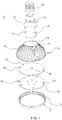
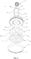
- an LED lighting lamp 10 with an enhanced heat dissipation function includes a main body 20 configured to be fitted and connected to a socket.
- a fitting hole 21 is formed inwardly through a center portion of an upper surface of the main body 20, and a plurality of heat dissipation fins 22 are formed along an outer peripheral surface of the fitting hole 21.
- a mounting surface 23 is formed in a lower side of the main body 20, and a single annular heat dissipation groove 24 or a plurality of annular heat dissipating grooves 24 are formed on the mounting surface.
- a LED module 30 is detachably installed while being in close contact with the mounting surface 23 formed in the lower side of the main body 20, and a plurality of LEDs 31 are installed on a bottom surface of the LED module 30.
- a separated cylindrical fitting boss 40 is fitted and coupled to the main body 20 through the fitting hole 21 formed in the main body 20, the fastening boss 40 is configured to be fastened by means of a screw to the LED module 30 which is in close contact with the mounting surface 23 on the main body 20, and a connection portion 50 fitted into and electrically connected to a socket provided on a ceiling, a wall surface, or the like is fitted and fixed to an outside of an upper portion of the fastening boss 40.
- a separate lens holder 60 is fitted and coupled to the bottom surface of the LED module 30 so as to be spaced apart therefrom by a predetermined distance, and lenses 61 are mounted on a surface of the lens holder 60 corresponding to positions corresponding to the respective LEDs 31 constituting the LED module 30 so as to diffuse illumination light emitted from the LEDs 31 and irradiate the illumination light.
- a separate ring-shaped fixing cap 70 is coupled by means of a screw to a lower end of the main body 20.
- the ring-shaped fixing cap 70 is coupled to the lower end of the main body 20 while enclosing edges of the LED module 30 and the lens holder 60, and thereafter, is fastened to the lower end by means of a screw such that an assembly of the LED module 30 and the lens holder 60 cannot be arbitrarily detached.
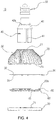
- a guide groove 21a is formed in a longitudinal direction at a position at which an inner peripheral surface of the fitting hole 21 on the main body 20 is divided by a predetermined angle
- a guide protrusion 41 is formed in the longitudinal direction on an outer peripheral surface of the fastening boss 40 corresponding to a position corresponding to the guide groove 21a
- a fastening hole 41a is formed inwardly from an lower end of the guide protrusion 41.
- a screw insertion hole 80 is formed in each of the mounting surface 23 on the main body 20 and a surface of the LED module 30 corresponding to the position corresponding to the fastening hole 41a on the guide protrusion 41.
- a plurality of air passages 25 which communicate with the annular heat dissipating groove 24 and through which external air flows into the heat dissipating groove 24 or heat flowing into the heat dissipating groove 24 flows to the outside may be radially formed on the mounting surface 23 on the main body 20.
- the annular heat dissipating groove 24 which is formed on the mounting surface 23 on the main body 20 is formed to protrude upward to have a depth being in contact with the heat dissipation fin 22.
- a plurality of protrusion jaws for forming a gap through which external air flows into the ring-shaped fixing cap 70 may be formed at regular intervals on an inner peripheral surface of the ring-shaped fixing cap 70.
- a plurality of coupling holes 32 are formed on an edge surface of the LED module 30, coupling protrusions 62 fitted into the coupling holes 32 are formed on an upper edge surface of the lens holder 60 corresponding to positions corresponding to the coupling holes 32, and a supporting jaw 62a which supports the edge of the coupling hole 32 is formed at an intermediate portion of the coupling protrusion 62.
- a cover 42 which covers an upper edge of the fitting hole 21 formed in the main body 20 is formed at an intermediate portion of the fastening boss 40, and a plurality of heat dissipating holes 42a are formed in an upper portion of the cover 42.
- the fastening boss 40 is fitted and coupled to the fitting hole 21 formed at the center portion of the main body 20 from above the fitting hole 21, and an upper surface of the LED holder 30 comes into close contact with the mounting surface 23 formed in a lower portion of the main body 20 such that the screw insertion hole 80 on the LED holder 30 coincides with the mounting surface 23.
- a screw is inserted through the screw insertion hole 80 from below the LED holder 30, and if the screw is coupled to the fastening hole 41a formed on a lower surface of the guide rib 41 on the fastening boss 40, the fastening of the LED holder 30 with respect to the main body 20 is completed.
- connection portion 50 for connecting the socket is fitted to an outer peripheral surface of an upper end of the fastening boss 40 such that the connection portion 50 is fixed, and the connection portion 50 and the LED module 30 are electrically connected to each other.
- the coupling protrusion 62 protruding from the edge of the upper surface of the lens holder 60 is fitted to the coupling hole 32 formed on the edge surface of the LED holder 30, the LED holder 30 and the lens holder 60 are coupled to each other in a state where the LED holder 30 and the lens holder 60 are separated from each other by a predetermined gap while the coupling hole 32 on the LED holder 30 is supported by the supporting jaw 62a on the coupling protrusion 62.
- the fixing cap 70 is coupled to an outer peripheral surface of the lower end of the main body 20 and is fastened by a screw in a state where outer peripheral surfaces of the LED holder 30 and the lens holder 60 are enclosed by the ring-shaped fixing cap 70, the assembly of the LED lighting lamp with an enhanced heat dissipation function according to the present invention is completed.
- connection portion 50 which is fitted and coupled to the upper end of the fastening boss 40 is connected to the socket installed in the ceiling or wall surface and power is supplied, illumination light is emitted while the LEDs 31 mounted on the LED module 30 are turned on, and the illumination light emitted from the LEDs is diffused and irradiated through a lens on the lens holder 60.
- the present invention relates an LED lighting lamp with an enhanced heat dissipation function, and can be applied to indoor or outdoor bulb and a lighting industry.
Landscapes
- Engineering & Computer Science (AREA)
- General Engineering & Computer Science (AREA)
- Physics & Mathematics (AREA)
- Microelectronics & Electronic Packaging (AREA)
- Optics & Photonics (AREA)
- Arrangement Of Elements, Cooling, Sealing, Or The Like Of Lighting Devices (AREA)
- Non-Portable Lighting Devices Or Systems Thereof (AREA)
Applications Claiming Priority (2)
| Application Number | Priority Date | Filing Date | Title |
|---|---|---|---|
| KR1020170070872A KR101934033B1 (ko) | 2017-06-07 | 2017-06-07 | 방열(放熱)기능이 강화된 엘이디 조명램프 |
| PCT/KR2018/006068 WO2018225973A1 (ko) | 2017-06-07 | 2018-05-29 | 방열기능이 강화된 엘이디 조명램프 |
Publications (3)
| Publication Number | Publication Date |
|---|---|
| EP3636995A1 true EP3636995A1 (de) | 2020-04-15 |
| EP3636995A4 EP3636995A4 (de) | 2021-03-10 |
| EP3636995B1 EP3636995B1 (de) | 2023-07-26 |
Family
ID=59514754
Family Applications (1)
| Application Number | Title | Priority Date | Filing Date |
|---|---|---|---|
| EP18814286.3A Active EP3636995B1 (de) | 2017-06-07 | 2018-05-29 | Led-beleuchtungslampe mit verbesserter wärmeableitungsfunktion |
Country Status (5)
| Country | Link |
|---|---|
| US (1) | US11454384B2 (de) |
| EP (1) | EP3636995B1 (de) |
| JP (1) | JP7014360B2 (de) |
| KR (1) | KR101934033B1 (de) |
| WO (1) | WO2018225973A1 (de) |
Cited By (1)
| Publication number | Priority date | Publication date | Assignee | Title |
|---|---|---|---|---|
| WO2023242183A1 (en) | 2022-06-17 | 2023-12-21 | Signify Holding B.V. | Improved thermal performance for spot lamps |
Families Citing this family (3)
| Publication number | Priority date | Publication date | Assignee | Title |
|---|---|---|---|---|
| KR101868454B1 (ko) | 2017-09-21 | 2018-06-18 | 미미라이팅주식회사 | 확산렌즈를 이용한 배광조절 기능이 구비된 led 등기구 |
| KR101885627B1 (ko) | 2018-02-12 | 2018-09-10 | 루멘전광(주) | 고반사 기능이 구비된 led 등기구 |
| CN216667616U (zh) * | 2021-12-14 | 2022-06-03 | 欧普照明股份有限公司 | 灯具 |
Family Cites Families (21)
| Publication number | Priority date | Publication date | Assignee | Title |
|---|---|---|---|---|
| JP2009267082A (ja) | 2008-04-25 | 2009-11-12 | San & K:Kk | Led電球 |
| KR200455749Y1 (ko) | 2009-06-12 | 2011-09-22 | 임채호 | 방열기능을 갖는 엘이디 조명등 |
| JP6140849B2 (ja) | 2009-11-09 | 2017-05-31 | エルジー イノテック カンパニー リミテッド | 照明装置 |
| KR101073927B1 (ko) * | 2010-06-23 | 2011-10-17 | 엘지전자 주식회사 | 조명장치 |
| KR101285889B1 (ko) | 2010-06-23 | 2013-07-11 | 엘지전자 주식회사 | Led 조명기구 |
| KR101055743B1 (ko) * | 2010-06-23 | 2011-08-11 | 엘지전자 주식회사 | 조명장치 |
| JP3164202U (ja) | 2010-09-06 | 2010-11-18 | 株式会社キシマ | Led電球 |
| JP2012195127A (ja) | 2011-03-16 | 2012-10-11 | Stanley Electric Co Ltd | Led照明装置 |
| JP5773136B2 (ja) * | 2011-03-25 | 2015-09-02 | 東芝ライテック株式会社 | ランプ装置および照明器具 |
| CN103492802B (zh) * | 2011-04-11 | 2018-06-05 | 莫列斯公司 | 灯具、散热片以及热传系统 |
| KR101285867B1 (ko) * | 2011-05-17 | 2013-07-12 | 주식회사 대진디엠피 | 엘이디 조명 램프 |
| CN102506325A (zh) * | 2011-11-02 | 2012-06-20 | 苏州红壹佰照明有限公司 | 夹层通透散热孔式led球泡灯 |
| CN102384452A (zh) * | 2011-11-25 | 2012-03-21 | 生迪光电科技股份有限公司 | 一种方便散热的led灯 |
| CN202361134U (zh) * | 2011-11-25 | 2012-08-01 | 生迪光电科技股份有限公司 | Led灯 |
| CA2859395C (en) * | 2011-12-13 | 2020-06-23 | Ephesus Lighting, Inc. | High intensity light-emitting diode luminaire assembly |
| CN203131534U (zh) * | 2013-03-20 | 2013-08-14 | 兴通工业股份有限公司 | Led灯泡 |
| KR101351986B1 (ko) * | 2013-04-05 | 2014-01-24 | 대원루스터 주식회사 | 접속구의 장착이 용이한 엘이디전구 |
| GB201407301D0 (en) * | 2014-04-25 | 2014-06-11 | Aurora Ltd | Improved led lamps and luminaires |
| JP6452372B2 (ja) | 2014-10-08 | 2019-01-16 | 三菱電機株式会社 | ランプ用の収納部材及びランプ及び照明装置 |
| US9420644B1 (en) * | 2015-03-31 | 2016-08-16 | Frank Shum | LED lighting |
| KR101686136B1 (ko) * | 2015-04-03 | 2016-12-13 | 동부라이텍 주식회사 | 조명장치 |
-
2017
- 2017-06-07 KR KR1020170070872A patent/KR101934033B1/ko active Active
-
2018
- 2018-05-29 JP JP2019567314A patent/JP7014360B2/ja active Active
- 2018-05-29 EP EP18814286.3A patent/EP3636995B1/de active Active
- 2018-05-29 WO PCT/KR2018/006068 patent/WO2018225973A1/ko not_active Ceased
- 2018-05-29 US US16/618,333 patent/US11454384B2/en active Active
Cited By (1)
| Publication number | Priority date | Publication date | Assignee | Title |
|---|---|---|---|---|
| WO2023242183A1 (en) | 2022-06-17 | 2023-12-21 | Signify Holding B.V. | Improved thermal performance for spot lamps |
Also Published As
| Publication number | Publication date |
|---|---|
| US11454384B2 (en) | 2022-09-27 |
| US20210156556A1 (en) | 2021-05-27 |
| EP3636995A4 (de) | 2021-03-10 |
| JP2020522856A (ja) | 2020-07-30 |
| KR20170072844A (ko) | 2017-06-27 |
| EP3636995B1 (de) | 2023-07-26 |
| WO2018225973A1 (ko) | 2018-12-13 |
| JP7014360B2 (ja) | 2022-02-01 |
| KR101934033B1 (ko) | 2018-12-31 |
Similar Documents
| Publication | Publication Date | Title |
|---|---|---|
| US8118449B2 (en) | Threaded LED retrofit module | |
| US8985815B2 (en) | Light bulb with upward and downward facing LEDs having heat dissipation | |
| KR200479421Y1 (ko) | 열 방출이 용이한 구형 조명등 | |
| US11454384B2 (en) | LED lighting lamp with enhanced heat dissipation function | |
| US10309623B2 (en) | Lamp having LED module fixing element with bayonet mount structure, and adapter structure | |
| MX2011005992A (es) | Aparato disipador de calor de forma radial y aparato de iluminación led en forma de foco que usa el mismo. | |
| JP2005251660A (ja) | 光源および照明装置 | |
| US9016904B2 (en) | LED lamp | |
| US11353172B2 (en) | Modular LED lamp system | |
| US8492960B2 (en) | Lamp with heat sink and lamp cover mounted on the heat sink | |
| KR100981683B1 (ko) | Led조명기구 | |
| JP2015109203A (ja) | Led照明装置 | |
| CN103822142B (zh) | Led射灯 | |
| EP2995848A1 (de) | Led-lampe mit festem sitz auf einer lampeneinheit durch einsatz einer steckdose | |
| EP2778517B1 (de) | Led-beleuchtungsvorrichtung | |
| CN202216016U (zh) | 一种分开式散热的led灯 | |
| KR101214959B1 (ko) | Led 조명 장치 | |
| KR200407799Y1 (ko) | 조명등 | |
| CN204300862U (zh) | 一种分体组装的工矿灯 | |
| WO2017219772A1 (zh) | 照明装置 | |
| KR100574840B1 (ko) | 조명등 | |
| KR20120080012A (ko) | Led 전구 | |
| JP2014135202A (ja) | 照明装置 | |
| CN209876803U (zh) | 一种新型圆形灯具 | |
| CN209146907U (zh) | 一种led筒灯 |
Legal Events
| Date | Code | Title | Description |
|---|---|---|---|
| STAA | Information on the status of an ep patent application or granted ep patent |
Free format text: STATUS: THE INTERNATIONAL PUBLICATION HAS BEEN MADE |
|
| PUAI | Public reference made under article 153(3) epc to a published international application that has entered the european phase |
Free format text: ORIGINAL CODE: 0009012 |
|
| STAA | Information on the status of an ep patent application or granted ep patent |
Free format text: STATUS: REQUEST FOR EXAMINATION WAS MADE |
|
| 17P | Request for examination filed |
Effective date: 20191212 |
|
| AK | Designated contracting states |
Kind code of ref document: A1 Designated state(s): AL AT BE BG CH CY CZ DE DK EE ES FI FR GB GR HR HU IE IS IT LI LT LU LV MC MK MT NL NO PL PT RO RS SE SI SK SM TR |
|
| AX | Request for extension of the european patent |
Extension state: BA ME |
|
| DAV | Request for validation of the european patent (deleted) | ||
| DAX | Request for extension of the european patent (deleted) | ||
| A4 | Supplementary search report drawn up and despatched |
Effective date: 20210205 |
|
| RIC1 | Information provided on ipc code assigned before grant |
Ipc: F21K 9/233 20160101ALI20210201BHEP Ipc: F21V 29/77 20150101ALI20210201BHEP Ipc: F21K 9/237 20160101ALI20210201BHEP Ipc: F21V 29/83 20150101ALI20210201BHEP Ipc: F21V 29/74 20150101AFI20210201BHEP Ipc: F21V 17/12 20060101ALI20210201BHEP Ipc: F21V 19/00 20060101ALI20210201BHEP Ipc: F21Y 115/10 20160101ALN20210201BHEP |
|
| GRAP | Despatch of communication of intention to grant a patent |
Free format text: ORIGINAL CODE: EPIDOSNIGR1 |
|
| STAA | Information on the status of an ep patent application or granted ep patent |
Free format text: STATUS: GRANT OF PATENT IS INTENDED |
|
| RIC1 | Information provided on ipc code assigned before grant |
Ipc: F21Y 115/10 20160101ALN20230113BHEP Ipc: F21V 19/00 20060101ALI20230113BHEP Ipc: F21V 29/83 20150101ALI20230113BHEP Ipc: F21V 29/77 20150101ALI20230113BHEP Ipc: F21K 9/233 20160101ALI20230113BHEP Ipc: F21V 17/12 20060101ALI20230113BHEP Ipc: F21K 9/237 20160101ALI20230113BHEP Ipc: F21V 29/74 20150101AFI20230113BHEP |
|
| RIC1 | Information provided on ipc code assigned before grant |
Ipc: F21Y 115/10 20160101ALN20230120BHEP Ipc: F21V 19/00 20060101ALI20230120BHEP Ipc: F21V 29/83 20150101ALI20230120BHEP Ipc: F21V 29/77 20150101ALI20230120BHEP Ipc: F21K 9/233 20160101ALI20230120BHEP Ipc: F21V 17/12 20060101ALI20230120BHEP Ipc: F21K 9/237 20160101ALI20230120BHEP Ipc: F21V 29/74 20150101AFI20230120BHEP |
|
| INTG | Intention to grant announced |
Effective date: 20230213 |
|
| GRAS | Grant fee paid |
Free format text: ORIGINAL CODE: EPIDOSNIGR3 |
|
| GRAA | (expected) grant |
Free format text: ORIGINAL CODE: 0009210 |
|
| STAA | Information on the status of an ep patent application or granted ep patent |
Free format text: STATUS: THE PATENT HAS BEEN GRANTED |
|
| AK | Designated contracting states |
Kind code of ref document: B1 Designated state(s): AL AT BE BG CH CY CZ DE DK EE ES FI FR GB GR HR HU IE IS IT LI LT LU LV MC MK MT NL NO PL PT RO RS SE SI SK SM TR |
|
| REG | Reference to a national code |
Ref country code: CH Ref legal event code: EP |
|
| REG | Reference to a national code |
Ref country code: DE Ref legal event code: R096 Ref document number: 602018054171 Country of ref document: DE |
|
| REG | Reference to a national code |
Ref country code: IE Ref legal event code: FG4D |
|
| REG | Reference to a national code |
Ref country code: LT Ref legal event code: MG9D |
|
| REG | Reference to a national code |
Ref country code: NL Ref legal event code: MP Effective date: 20230726 |
|
| REG | Reference to a national code |
Ref country code: AT Ref legal event code: MK05 Ref document number: 1592294 Country of ref document: AT Kind code of ref document: T Effective date: 20230726 |
|
| PG25 | Lapsed in a contracting state [announced via postgrant information from national office to epo] |
Ref country code: NL Free format text: LAPSE BECAUSE OF FAILURE TO SUBMIT A TRANSLATION OF THE DESCRIPTION OR TO PAY THE FEE WITHIN THE PRESCRIBED TIME-LIMIT Effective date: 20230726 |
|
| PG25 | Lapsed in a contracting state [announced via postgrant information from national office to epo] |
Ref country code: GR Free format text: LAPSE BECAUSE OF FAILURE TO SUBMIT A TRANSLATION OF THE DESCRIPTION OR TO PAY THE FEE WITHIN THE PRESCRIBED TIME-LIMIT Effective date: 20231027 |
|
| PG25 | Lapsed in a contracting state [announced via postgrant information from national office to epo] |
Ref country code: IS Free format text: LAPSE BECAUSE OF FAILURE TO SUBMIT A TRANSLATION OF THE DESCRIPTION OR TO PAY THE FEE WITHIN THE PRESCRIBED TIME-LIMIT Effective date: 20231126 |
|
| PG25 | Lapsed in a contracting state [announced via postgrant information from national office to epo] |
Ref country code: SE Free format text: LAPSE BECAUSE OF FAILURE TO SUBMIT A TRANSLATION OF THE DESCRIPTION OR TO PAY THE FEE WITHIN THE PRESCRIBED TIME-LIMIT Effective date: 20230726 Ref country code: RS Free format text: LAPSE BECAUSE OF FAILURE TO SUBMIT A TRANSLATION OF THE DESCRIPTION OR TO PAY THE FEE WITHIN THE PRESCRIBED TIME-LIMIT Effective date: 20230726 Ref country code: PT Free format text: LAPSE BECAUSE OF FAILURE TO SUBMIT A TRANSLATION OF THE DESCRIPTION OR TO PAY THE FEE WITHIN THE PRESCRIBED TIME-LIMIT Effective date: 20231127 Ref country code: NO Free format text: LAPSE BECAUSE OF FAILURE TO SUBMIT A TRANSLATION OF THE DESCRIPTION OR TO PAY THE FEE WITHIN THE PRESCRIBED TIME-LIMIT Effective date: 20231026 Ref country code: LV Free format text: LAPSE BECAUSE OF FAILURE TO SUBMIT A TRANSLATION OF THE DESCRIPTION OR TO PAY THE FEE WITHIN THE PRESCRIBED TIME-LIMIT Effective date: 20230726 Ref country code: LT Free format text: LAPSE BECAUSE OF FAILURE TO SUBMIT A TRANSLATION OF THE DESCRIPTION OR TO PAY THE FEE WITHIN THE PRESCRIBED TIME-LIMIT Effective date: 20230726 Ref country code: IS Free format text: LAPSE BECAUSE OF FAILURE TO SUBMIT A TRANSLATION OF THE DESCRIPTION OR TO PAY THE FEE WITHIN THE PRESCRIBED TIME-LIMIT Effective date: 20231126 Ref country code: HR Free format text: LAPSE BECAUSE OF FAILURE TO SUBMIT A TRANSLATION OF THE DESCRIPTION OR TO PAY THE FEE WITHIN THE PRESCRIBED TIME-LIMIT Effective date: 20230726 Ref country code: GR Free format text: LAPSE BECAUSE OF FAILURE TO SUBMIT A TRANSLATION OF THE DESCRIPTION OR TO PAY THE FEE WITHIN THE PRESCRIBED TIME-LIMIT Effective date: 20231027 Ref country code: FI Free format text: LAPSE BECAUSE OF FAILURE TO SUBMIT A TRANSLATION OF THE DESCRIPTION OR TO PAY THE FEE WITHIN THE PRESCRIBED TIME-LIMIT Effective date: 20230726 Ref country code: AT Free format text: LAPSE BECAUSE OF FAILURE TO SUBMIT A TRANSLATION OF THE DESCRIPTION OR TO PAY THE FEE WITHIN THE PRESCRIBED TIME-LIMIT Effective date: 20230726 |
|
| PG25 | Lapsed in a contracting state [announced via postgrant information from national office to epo] |
Ref country code: PL Free format text: LAPSE BECAUSE OF FAILURE TO SUBMIT A TRANSLATION OF THE DESCRIPTION OR TO PAY THE FEE WITHIN THE PRESCRIBED TIME-LIMIT Effective date: 20230726 |
|
| PG25 | Lapsed in a contracting state [announced via postgrant information from national office to epo] |
Ref country code: ES Free format text: LAPSE BECAUSE OF FAILURE TO SUBMIT A TRANSLATION OF THE DESCRIPTION OR TO PAY THE FEE WITHIN THE PRESCRIBED TIME-LIMIT Effective date: 20230726 |
|
| REG | Reference to a national code |
Ref country code: DE Ref legal event code: R097 Ref document number: 602018054171 Country of ref document: DE |
|
| PG25 | Lapsed in a contracting state [announced via postgrant information from national office to epo] |
Ref country code: SM Free format text: LAPSE BECAUSE OF FAILURE TO SUBMIT A TRANSLATION OF THE DESCRIPTION OR TO PAY THE FEE WITHIN THE PRESCRIBED TIME-LIMIT Effective date: 20230726 Ref country code: RO Free format text: LAPSE BECAUSE OF FAILURE TO SUBMIT A TRANSLATION OF THE DESCRIPTION OR TO PAY THE FEE WITHIN THE PRESCRIBED TIME-LIMIT Effective date: 20230726 Ref country code: ES Free format text: LAPSE BECAUSE OF FAILURE TO SUBMIT A TRANSLATION OF THE DESCRIPTION OR TO PAY THE FEE WITHIN THE PRESCRIBED TIME-LIMIT Effective date: 20230726 Ref country code: EE Free format text: LAPSE BECAUSE OF FAILURE TO SUBMIT A TRANSLATION OF THE DESCRIPTION OR TO PAY THE FEE WITHIN THE PRESCRIBED TIME-LIMIT Effective date: 20230726 Ref country code: DK Free format text: LAPSE BECAUSE OF FAILURE TO SUBMIT A TRANSLATION OF THE DESCRIPTION OR TO PAY THE FEE WITHIN THE PRESCRIBED TIME-LIMIT Effective date: 20230726 Ref country code: CZ Free format text: LAPSE BECAUSE OF FAILURE TO SUBMIT A TRANSLATION OF THE DESCRIPTION OR TO PAY THE FEE WITHIN THE PRESCRIBED TIME-LIMIT Effective date: 20230726 Ref country code: SK Free format text: LAPSE BECAUSE OF FAILURE TO SUBMIT A TRANSLATION OF THE DESCRIPTION OR TO PAY THE FEE WITHIN THE PRESCRIBED TIME-LIMIT Effective date: 20230726 |
|
| PG25 | Lapsed in a contracting state [announced via postgrant information from national office to epo] |
Ref country code: IT Free format text: LAPSE BECAUSE OF FAILURE TO SUBMIT A TRANSLATION OF THE DESCRIPTION OR TO PAY THE FEE WITHIN THE PRESCRIBED TIME-LIMIT Effective date: 20230726 |
|
| PLBE | No opposition filed within time limit |
Free format text: ORIGINAL CODE: 0009261 |
|
| STAA | Information on the status of an ep patent application or granted ep patent |
Free format text: STATUS: NO OPPOSITION FILED WITHIN TIME LIMIT |
|
| 26N | No opposition filed |
Effective date: 20240429 |
|
| PG25 | Lapsed in a contracting state [announced via postgrant information from national office to epo] |
Ref country code: SI Free format text: LAPSE BECAUSE OF FAILURE TO SUBMIT A TRANSLATION OF THE DESCRIPTION OR TO PAY THE FEE WITHIN THE PRESCRIBED TIME-LIMIT Effective date: 20230726 |
|
| PG25 | Lapsed in a contracting state [announced via postgrant information from national office to epo] |
Ref country code: BG Free format text: LAPSE BECAUSE OF FAILURE TO SUBMIT A TRANSLATION OF THE DESCRIPTION OR TO PAY THE FEE WITHIN THE PRESCRIBED TIME-LIMIT Effective date: 20230726 |
|
| PG25 | Lapsed in a contracting state [announced via postgrant information from national office to epo] |
Ref country code: BG Free format text: LAPSE BECAUSE OF FAILURE TO SUBMIT A TRANSLATION OF THE DESCRIPTION OR TO PAY THE FEE WITHIN THE PRESCRIBED TIME-LIMIT Effective date: 20230726 |
|
| REG | Reference to a national code |
Ref country code: CH Ref legal event code: PL |
|
| PG25 | Lapsed in a contracting state [announced via postgrant information from national office to epo] |
Ref country code: MC Free format text: LAPSE BECAUSE OF FAILURE TO SUBMIT A TRANSLATION OF THE DESCRIPTION OR TO PAY THE FEE WITHIN THE PRESCRIBED TIME-LIMIT Effective date: 20230726 |
|
| PG25 | Lapsed in a contracting state [announced via postgrant information from national office to epo] |
Ref country code: LU Free format text: LAPSE BECAUSE OF NON-PAYMENT OF DUE FEES Effective date: 20240529 |
|
| GBPC | Gb: european patent ceased through non-payment of renewal fee |
Effective date: 20240529 |
|
| PG25 | Lapsed in a contracting state [announced via postgrant information from national office to epo] |
Ref country code: MC Free format text: LAPSE BECAUSE OF FAILURE TO SUBMIT A TRANSLATION OF THE DESCRIPTION OR TO PAY THE FEE WITHIN THE PRESCRIBED TIME-LIMIT Effective date: 20230726 Ref country code: LU Free format text: LAPSE BECAUSE OF NON-PAYMENT OF DUE FEES Effective date: 20240529 Ref country code: CH Free format text: LAPSE BECAUSE OF NON-PAYMENT OF DUE FEES Effective date: 20240531 |
|
| REG | Reference to a national code |
Ref country code: BE Ref legal event code: MM Effective date: 20240531 |
|
| PG25 | Lapsed in a contracting state [announced via postgrant information from national office to epo] |
Ref country code: IE Free format text: LAPSE BECAUSE OF NON-PAYMENT OF DUE FEES Effective date: 20240529 |
|
| PG25 | Lapsed in a contracting state [announced via postgrant information from national office to epo] |
Ref country code: BE Free format text: LAPSE BECAUSE OF NON-PAYMENT OF DUE FEES Effective date: 20240531 |
|
| PG25 | Lapsed in a contracting state [announced via postgrant information from national office to epo] |
Ref country code: FR Free format text: LAPSE BECAUSE OF NON-PAYMENT OF DUE FEES Effective date: 20240531 |
|
| PG25 | Lapsed in a contracting state [announced via postgrant information from national office to epo] |
Ref country code: GB Free format text: LAPSE BECAUSE OF NON-PAYMENT OF DUE FEES Effective date: 20240529 |
|
| PGFP | Annual fee paid to national office [announced via postgrant information from national office to epo] |
Ref country code: DE Payment date: 20250529 Year of fee payment: 8 |
|
| PG25 | Lapsed in a contracting state [announced via postgrant information from national office to epo] |
Ref country code: CY Free format text: LAPSE BECAUSE OF FAILURE TO SUBMIT A TRANSLATION OF THE DESCRIPTION OR TO PAY THE FEE WITHIN THE PRESCRIBED TIME-LIMIT; INVALID AB INITIO Effective date: 20180529 |
|
| PG25 | Lapsed in a contracting state [announced via postgrant information from national office to epo] |
Ref country code: HU Free format text: LAPSE BECAUSE OF FAILURE TO SUBMIT A TRANSLATION OF THE DESCRIPTION OR TO PAY THE FEE WITHIN THE PRESCRIBED TIME-LIMIT; INVALID AB INITIO Effective date: 20180529 |